Endoscopic surgical clip applier and handle assemblies for use therewith
Baril , et al. November 17, 2
U.S. patent number 10,835,260 [Application Number 16/041,965] was granted by the patent office on 2020-11-17 for endoscopic surgical clip applier and handle assemblies for use therewith. This patent grant is currently assigned to COVIDIEN LP. The grantee listed for this patent is Covidien LP. Invention is credited to Jacob C. Baril, Brian J. Creston, Matthew A. Dinino, Thomas A. Zammataro.


View All Diagrams
| United States Patent | 10,835,260 |
| Baril , et al. | November 17, 2020 |
Endoscopic surgical clip applier and handle assemblies for use therewith
Abstract
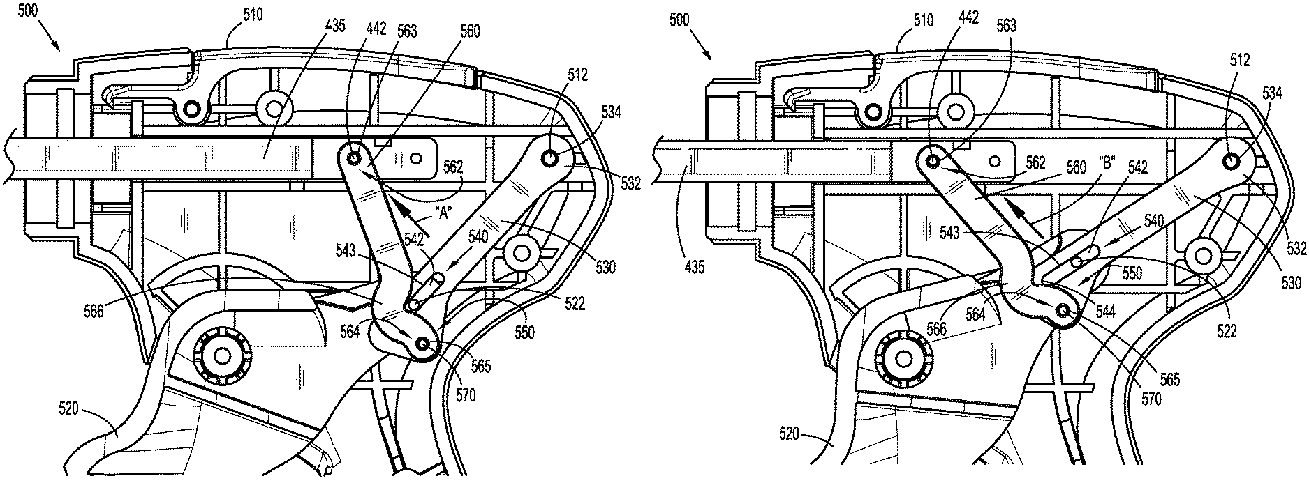
A handle assembly for use with a surgical instrument including a housing, a movable handle, a plunger, a first linkage, and a second linkage. The movable handle is pivotably mounted to the housing about a handle pin. The plunger is disposed at least partially within the housing. Distal translation of the plunger relative to the housing is configured to affect a function of the surgical instrument. The first linkage is disposed at least partially within the housing. A first portion of the first linkage is pivotable about the housing, and a second portion of the first linkage is slidable relative to the handle pin. The second linkage is disposed at least partially within the housing. A first portion of the second linkage is pivotable about the plunger, and a second portion of the second linkage is pivotable about a third portion of the first linkage.
| Inventors: | Baril; Jacob C. (Norwalk, CT), Creston; Brian J. (West Haven, CT), Zammataro; Thomas A. (Hamden, CT), Dinino; Matthew A. (Newington, CT) | ||||||||||
|---|---|---|---|---|---|---|---|---|---|---|---|
| Applicant: |
|
||||||||||
| Assignee: | COVIDIEN LP (Mansfield,
MA) |
||||||||||
| Family ID: | 65630111 | ||||||||||
| Appl. No.: | 16/041,965 | ||||||||||
| Filed: | July 23, 2018 |
Prior Publication Data
| Document Identifier | Publication Date | |
|---|---|---|
| US 20190076147 A1 | Mar 14, 2019 | |
Related U.S. Patent Documents
| Application Number | Filing Date | Patent Number | Issue Date | ||
|---|---|---|---|---|---|
| 62557773 | Sep 13, 2017 | ||||
| Current U.S. Class: | 1/1 |
| Current CPC Class: | A61B 17/1285 (20130101); A61B 2017/0046 (20130101); A61B 2017/00407 (20130101); A61B 2017/00464 (20130101) |
| Current International Class: | A61B 17/10 (20060101); A61B 17/128 (20060101); A61B 17/00 (20060101) |
References Cited [Referenced By]
U.S. Patent Documents
| 3120230 | February 1964 | Skold |
| 3363628 | January 1968 | Wood |
| 3638847 | February 1972 | Noiles et al. |
| 3675688 | July 1972 | Bryan et al. |
| 3735762 | May 1973 | Bryan et al. |
| 3867944 | February 1975 | Samuels |
| 4242902 | January 1981 | Green |
| 4296751 | October 1981 | Blake, III et al. |
| 4372316 | February 1983 | Blake, III et al. |
| 4408603 | October 1983 | Blake, III et al. |
| 4412539 | November 1983 | Jarvik |
| 4418694 | December 1983 | Beroff et al. |
| 4471780 | September 1984 | Menges et al. |
| 4480640 | November 1984 | Becht |
| 4480641 | November 1984 | Failla et al. |
| 4487204 | December 1984 | Hrouda |
| 4487205 | December 1984 | Di Giovanni et al. |
| 4491133 | January 1985 | Menges et al. |
| 4492232 | January 1985 | Green |
| 4498476 | February 1985 | Cerwin et al. |
| 4500024 | February 1985 | DiGiovanni et al. |
| 4509518 | April 1985 | McGarry et al. |
| 4512345 | April 1985 | Green |
| 4522207 | June 1985 | Klieman et al. |
| 4532925 | August 1985 | Blake, III |
| 4534351 | August 1985 | Rothfuss et al. |
| 4545377 | October 1985 | Cerwin et al. |
| 4549544 | October 1985 | Favaron |
| 4556058 | December 1985 | Green |
| 4557263 | December 1985 | Green |
| 4562839 | January 1986 | Blake, III et al. |
| 4572183 | February 1986 | Juska |
| 4576165 | March 1986 | Green et al. |
| 4576166 | March 1986 | Montgomery et al. |
| 4590937 | May 1986 | Deniega |
| 4598711 | July 1986 | Deniega |
| 4602631 | July 1986 | Funatsu |
| 4611595 | September 1986 | Klieman et al. |
| 4612932 | September 1986 | Caspar et al. |
| 4616650 | October 1986 | Green et al. |
| 4616651 | October 1986 | Golden |
| 4624254 | November 1986 | McGarry et al. |
| 4637395 | January 1987 | Caspar et al. |
| 4646740 | March 1987 | Peters et al. |
| 4647504 | March 1987 | Kimimura et al. |
| 4658822 | April 1987 | Kees, Jr. |
| 4660558 | April 1987 | Kees, Jr. |
| 4662373 | May 1987 | Montgomery et al. |
| 4662374 | May 1987 | Blake, III |
| 4671278 | June 1987 | Chin |
| 4671282 | June 1987 | Tretbar |
| 4674504 | June 1987 | Klieman et al. |
| 4681107 | July 1987 | Kees, Jr. |
| 4696396 | September 1987 | Samuels |
| 4702247 | October 1987 | Blake, III et al. |
| 4706668 | November 1987 | Backer |
| 4712549 | December 1987 | Peters et al. |
| 4733666 | March 1988 | Mercer, Jr. |
| 4759364 | July 1988 | Boebel |
| 4765335 | August 1988 | Schmidt et al. |
| 4777949 | October 1988 | Perlin |
| 4796625 | January 1989 | Kees, Jr. |
| 4799481 | January 1989 | Transue et al. |
| 4815466 | March 1989 | Perlin |
| 4821721 | April 1989 | Chin et al. |
| 4822348 | April 1989 | Casey |
| 4834096 | May 1989 | Oh et al. |
| 4850355 | July 1989 | Brooks et al. |
| 4854317 | August 1989 | Braun |
| 4856517 | August 1989 | Collins et al. |
| 4929239 | May 1990 | Braun |
| 4931058 | June 1990 | Cooper |
| 4934364 | June 1990 | Green |
| 4957500 | September 1990 | Liang et al. |
| 4966603 | October 1990 | Focelle et al. |
| 4967949 | November 1990 | Sandhaus |
| 4983176 | January 1991 | Cushman et al. |
| 4988355 | January 1991 | Leveen et al. |
| 5002552 | March 1991 | Casey |
| 5026379 | June 1991 | Yoon |
| 5030224 | July 1991 | Wright et al. |
| 5030226 | July 1991 | Green et al. |
| 5032127 | July 1991 | Frazee et al. |
| 5035692 | July 1991 | Lyon et al. |
| 5047038 | September 1991 | Peters et al. |
| 5049152 | September 1991 | Simon et al. |
| 5049153 | September 1991 | Nakao et al. |
| 5053045 | October 1991 | Schmidt et al. |
| 5059202 | October 1991 | Liang et al. |
| 5062563 | November 1991 | Green et al. |
| 5062846 | November 1991 | Oh et al. |
| 5078731 | January 1992 | Hayhurst |
| 5084057 | January 1992 | Green |
| 5100416 | March 1992 | Oh et al. |
| 5100420 | March 1992 | Green et al. |
| 5104394 | April 1992 | Knoepfler |
| 5104395 | April 1992 | Thornton et al. |
| 5112343 | May 1992 | Thornton |
| 5122150 | June 1992 | Puig |
| 5127915 | July 1992 | Mattson |
| 5129885 | July 1992 | Green et al. |
| 5156608 | October 1992 | Troidl et al. |
| 5160339 | November 1992 | Chen et al. |
| 5163945 | November 1992 | Ortiz et al. |
| 5171247 | December 1992 | Hughett et al. |
| 5171249 | December 1992 | Stefanchik et al. |
| 5171250 | December 1992 | Yoon |
| 5171251 | December 1992 | Bregen et al. |
| 5171252 | December 1992 | Friedland |
| 5171253 | December 1992 | Klieman |
| 5192288 | March 1993 | Thompson et al. |
| 5197970 | March 1993 | Green et al. |
| 5199566 | April 1993 | Ortiz et al. |
| 5201746 | April 1993 | Shichman |
| 5201900 | April 1993 | Nardella |
| 5207691 | May 1993 | Nardella |
| 5207692 | May 1993 | Kraus et al. |
| 5217473 | June 1993 | Yoon |
| 5219353 | June 1993 | Garvey, III et al. |
| 5246450 | September 1993 | Thornton et al. |
| 5269792 | December 1993 | Kovac et al. |
| 5281228 | January 1994 | Wolfson |
| 5282807 | February 1994 | Knoepfler |
| 5282808 | February 1994 | Kovac et al. |
| 5282832 | February 1994 | Toso et al. |
| 5289963 | March 1994 | McGarry et al. |
| 5290299 | March 1994 | Fain et al. |
| 5300081 | April 1994 | Young et al. |
| 5304183 | April 1994 | Gourlay et al. |
| 5306280 | April 1994 | Bregen et al. |
| 5306283 | April 1994 | Conners |
| 5312426 | May 1994 | Segawa et al. |
| 5330442 | July 1994 | Green et al. |
| 5330487 | July 1994 | Thornton et al. |
| 5340360 | August 1994 | Stefanchik |
| 5342373 | August 1994 | Stefanchik et al. |
| 5354304 | October 1994 | Allen et al. |
| 5354306 | October 1994 | Garvey, III et al. |
| 5356064 | October 1994 | Green et al. |
| 5366458 | November 1994 | Korthoff et al. |
| 5366459 | November 1994 | Yoon |
| 5368600 | November 1994 | Failla et al. |
| 5381943 | January 1995 | Allen et al. |
| 5382253 | January 1995 | Hogendijk |
| 5382254 | January 1995 | McGarry et al. |
| 5382255 | January 1995 | Castro et al. |
| 5383880 | January 1995 | Hooven |
| 5383881 | January 1995 | Green et al. |
| 5395375 | March 1995 | Turkel et al. |
| 5395381 | March 1995 | Green et al. |
| 5403327 | April 1995 | Thornton et al. |
| 5409498 | April 1995 | Braddock et al. |
| 5413584 | May 1995 | Schulze |
| 5423835 | June 1995 | Green et al. |
| 5425740 | June 1995 | Hutchinson, Jr. |
| 5431667 | July 1995 | Thompson et al. |
| 5431668 | July 1995 | Burbank, III et al. |
| 5431669 | July 1995 | Thompson et al. |
| 5439468 | August 1995 | Schulze et al. |
| 5441509 | August 1995 | Vidal et al. |
| 5447513 | September 1995 | Davison et al. |
| 5449365 | September 1995 | Green et al. |
| 5462555 | October 1995 | Bolanos et al. |
| 5462558 | October 1995 | Kolesa et al. |
| 5464416 | November 1995 | Steckel |
| 5474566 | December 1995 | Alesi et al. |
| 5474567 | December 1995 | Stefanchik et al. |
| 5474572 | December 1995 | Hayhurst |
| 5487499 | January 1996 | Sorrentino et al. |
| 5487746 | January 1996 | Yu et al. |
| 5501693 | March 1996 | Gravener |
| 5509920 | April 1996 | Phillips et al. |
| 5514149 | May 1996 | Green et al. |
| 5520701 | May 1996 | Lerch |
| 5527318 | June 1996 | McGarry |
| 5527319 | June 1996 | Green et al. |
| 5527320 | June 1996 | Carruthers et al. |
| 5542949 | August 1996 | Yoon |
| 5547474 | August 1996 | Kloeckl et al. |
| 5562655 | October 1996 | Mittelstadt et al. |
| 5569274 | October 1996 | Rapacki et al. |
| 5571121 | November 1996 | Heifetz |
| 5575802 | November 1996 | McQuilkin et al. |
| 5582615 | December 1996 | Foshee et al. |
| 5584840 | December 1996 | Ramsey et al. |
| 5591178 | January 1997 | Green et al. |
| 5593414 | January 1997 | Shipp et al. |
| 5593421 | January 1997 | Bauer |
| 5601573 | February 1997 | Fogelberg et al. |
| 5601574 | February 1997 | Stefanchik et al. |
| 5607436 | March 1997 | Pratt et al. |
| 5618291 | April 1997 | Thompson et al. |
| 5618306 | April 1997 | Roth et al. |
| 5620452 | April 1997 | Yoon |
| 5626585 | May 1997 | Mittelstadt et al. |
| 5626586 | May 1997 | Pistl et al. |
| 5626587 | May 1997 | Bishop et al. |
| 5626592 | May 1997 | Phillips et al. |
| RE35525 | June 1997 | Stefanchik et al. |
| 5634930 | June 1997 | Thornton et al. |
| 5643291 | July 1997 | Pier et al. |
| 5645551 | July 1997 | Green et al. |
| 5645553 | July 1997 | Kolesa et al. |
| 5649937 | July 1997 | Bito et al. |
| 5653720 | August 1997 | Johnson et al. |
| 5662662 | September 1997 | Bishop |
| 5662676 | September 1997 | Koninckx |
| 5662679 | September 1997 | Voss et al. |
| 5665097 | September 1997 | Baker et al. |
| 5676676 | October 1997 | Porter |
| 5681330 | October 1997 | Hughett et al. |
| 5683405 | November 1997 | Yacoubian et al. |
| 5695502 | December 1997 | Pier et al. |
| 5695505 | December 1997 | Yoon |
| 5697938 | December 1997 | Jensen et al. |
| 5697942 | December 1997 | Palti |
| 5700270 | December 1997 | Peyser et al. |
| 5700271 | December 1997 | Whitfield et al. |
| 5702048 | December 1997 | Eberlin |
| 5709706 | January 1998 | Kienzle et al. |
| 5713911 | February 1998 | Racenet et al. |
| 5713912 | February 1998 | Porter |
| 5720756 | February 1998 | Green et al. |
| 5722982 | March 1998 | Ferreira et al. |
| 5725537 | March 1998 | Green et al. |
| 5725538 | March 1998 | Green et al. |
| 5725542 | March 1998 | Yoon |
| 5733295 | March 1998 | Back et al. |
| 5743310 | April 1998 | Moran |
| 5749881 | May 1998 | Sackier et al. |
| 5755726 | May 1998 | Pratt et al. |
| 5766189 | June 1998 | Matsuno |
| 5769857 | June 1998 | Reztzov et al. |
| 5772673 | June 1998 | Cuny et al. |
| 5776146 | July 1998 | Sackier et al. |
| 5776147 | July 1998 | Dolendo |
| 5779718 | July 1998 | Green et al. |
| 5779720 | July 1998 | Walder-Utz et al. |
| 5782844 | July 1998 | Yoon et al. |
| 5788698 | August 1998 | Savornin |
| 5792149 | August 1998 | Sherts et al. |
| 5792150 | August 1998 | Pratt et al. |
| 5797922 | August 1998 | Hessel et al. |
| 5810853 | September 1998 | Yoon |
| 5817116 | October 1998 | Takahashi et al. |
| 5827306 | October 1998 | Yoon |
| 5827323 | October 1998 | Klieman et al. |
| 5833695 | November 1998 | Yoon |
| 5833696 | November 1998 | Whitfield et al. |
| 5833700 | November 1998 | Fogelberg et al. |
| 5835199 | November 1998 | Phillips et al. |
| 5843097 | December 1998 | Mayenberger et al. |
| 5843101 | December 1998 | Fry |
| 5846255 | December 1998 | Casey |
| 5849019 | December 1998 | Yoon |
| 5858018 | January 1999 | Shipp et al. |
| 5861005 | January 1999 | Kontos |
| 5868759 | February 1999 | Peyser et al. |
| 5868761 | February 1999 | Nicholas et al. |
| 5876410 | March 1999 | Petillo |
| 5895394 | April 1999 | Kienzle et al. |
| 5897565 | April 1999 | Foster |
| 5904693 | May 1999 | Dicesare et al. |
| 5906625 | May 1999 | Bito et al. |
| 5913862 | June 1999 | Ramsey et al. |
| 5913876 | June 1999 | Taylor et al. |
| 5918791 | July 1999 | Sorrentino et al. |
| 5921996 | July 1999 | Sherman |
| 5921997 | July 1999 | Fogelberg et al. |
| 5928251 | July 1999 | Aranyi et al. |
| 5938667 | August 1999 | Peyser et al. |
| 5951574 | September 1999 | Stefanchik et al. |
| 5972003 | October 1999 | Rousseau et al. |
| 5976159 | November 1999 | Bolduc et al. |
| 5993465 | November 1999 | Shipp et al. |
| 6004335 | December 1999 | Vaitekunas et al. |
| 6009551 | December 1999 | Sheynblat |
| 6017358 | January 2000 | Yoon et al. |
| 6045560 | April 2000 | McKean et al. |
| 6053908 | April 2000 | Crainich et al. |
| RE36720 | May 2000 | Green et al. |
| 6059799 | May 2000 | Aranyi et al. |
| 6099536 | August 2000 | Petillo |
| 6099537 | August 2000 | Sugai et al. |
| 6139555 | October 2000 | Hart et al. |
| 6210418 | April 2001 | Storz et al. |
| 6217590 | April 2001 | Levinson |
| 6228097 | May 2001 | Levinson et al. |
| 6241740 | June 2001 | Davis et al. |
| 6258105 | July 2001 | Hart et al. |
| 6261302 | July 2001 | Voegele et al. |
| 6273898 | August 2001 | Kienzle et al. |
| 6277131 | August 2001 | Kalikow |
| 6306149 | October 2001 | Meade |
| 6318619 | November 2001 | Lee |
| 6322571 | November 2001 | Adams |
| 6350269 | February 2002 | Shipp et al. |
| 6352541 | March 2002 | Kienzle et al. |
| 6391035 | May 2002 | Appleby et al. |
| 6423079 | July 2002 | Blake, III |
| 6428548 | August 2002 | Durgin et al. |
| 6440144 | August 2002 | Bacher |
| 6461363 | October 2002 | Gadberry et al. |
| 6464710 | October 2002 | Foster |
| 6494886 | December 2002 | Wilk et al. |
| 6517536 | February 2003 | Hooven et al. |
| 6520972 | February 2003 | Peters |
| 6527786 | March 2003 | Davis et al. |
| 6537289 | March 2003 | Kayan |
| 6546935 | April 2003 | Hooven |
| 6551333 | April 2003 | Kuhns et al. |
| 6562051 | May 2003 | Bolduc et al. |
| 6569171 | May 2003 | DeGuillebon et al. |
| 6579304 | June 2003 | Hart et al. |
| 6599298 | July 2003 | Forster et al. |
| 6602252 | August 2003 | Mollenauer |
| 6607540 | August 2003 | Shipp |
| 6613060 | September 2003 | Adams et al. |
| 6626916 | September 2003 | Yeung et al. |
| 6626922 | September 2003 | Hart et al. |
| 6648898 | November 2003 | Baxter |
| 6652538 | November 2003 | Kayan et al. |
| 6652539 | November 2003 | Shipp et al. |
| 6656193 | December 2003 | Grant et al. |
| 6673083 | January 2004 | Kayan et al. |
| 6676659 | January 2004 | Hutchins et al. |
| 6679894 | January 2004 | Damarati |
| RE38445 | February 2004 | Pistl et al. |
| 6695854 | February 2004 | Kayan et al. |
| 6706057 | March 2004 | Bidoia et al. |
| 6716226 | April 2004 | Sixto, Jr. et al. |
| 6723109 | April 2004 | Solingen |
| 6733514 | May 2004 | Miser |
| 6743240 | June 2004 | Smith et al. |
| 6743241 | June 2004 | Kerr |
| 6773438 | August 2004 | Knodel et al. |
| 6773440 | August 2004 | Gannoe et al. |
| 6776783 | August 2004 | Frantzen et al. |
| 6776784 | August 2004 | Ginn |
| 6780195 | August 2004 | Porat |
| 6793663 | September 2004 | Kneifel et al. |
| 6793664 | September 2004 | Mazzocchi et al. |
| 6802848 | October 2004 | Anderson et al. |
| 6814742 | November 2004 | Kimura et al. |
| 6818009 | November 2004 | Hart et al. |
| 6821273 | November 2004 | Mollenauer |
| 6821284 | November 2004 | Sturtz et al. |
| 6821285 | November 2004 | Laufer et al. |
| 6824547 | November 2004 | Wilson, Jr. et al. |
| 6824548 | November 2004 | Smith et al. |
| 6835199 | December 2004 | McGuckin, Jr. et al. |
| 6835200 | December 2004 | Laufer et al. |
| 6837893 | January 2005 | Miller |
| 6837894 | January 2005 | Pugsley, Jr. et al. |
| 6837895 | January 2005 | Mayenberger |
| 6840945 | January 2005 | Manetakis et al. |
| 6843794 | January 2005 | Sixto, Jr. et al. |
| 6849078 | February 2005 | Durgin et al. |
| 6849079 | February 2005 | Blake, III et al. |
| 6853879 | February 2005 | Sunaoshi |
| 6869435 | March 2005 | Blake, III |
| 6869436 | March 2005 | Wendlandt |
| 6889116 | May 2005 | Jinno |
| 6896676 | May 2005 | Zubok et al. |
| 6896682 | May 2005 | McClellan et al. |
| 6896684 | May 2005 | Monassevitch et al. |
| 6905503 | June 2005 | Gifford, III et al. |
| 6911032 | June 2005 | Jugenheimer et al. |
| 6911033 | June 2005 | de Guillebon et al. |
| 6913607 | July 2005 | Ainsworth et al. |
| 6916327 | July 2005 | Northrup, III et al. |
| 6916332 | July 2005 | Adams |
| 6923818 | August 2005 | Muramatsu et al. |
| 6939356 | September 2005 | Debbas |
| 6942674 | September 2005 | Belef et al. |
| 6942676 | September 2005 | Buelna |
| 6945978 | September 2005 | Hyde |
| 6945979 | September 2005 | Kortenbach et al. |
| 6949107 | September 2005 | McGuckin, Jr. et al. |
| 6953465 | October 2005 | Dieck et al. |
| 6955643 | October 2005 | Gellman et al. |
| 6959852 | November 2005 | Shelton, IV et al. |
| 6960218 | November 2005 | Rennich |
| 6960221 | November 2005 | Ho et al. |
| 6962594 | November 2005 | Thevenet |
| 6963792 | November 2005 | Green |
| 6964363 | November 2005 | Wales et al. |
| 6964668 | November 2005 | Modesitt et al. |
| 6966875 | November 2005 | Longobardi |
| 6966917 | November 2005 | Suyker et al. |
| 6966919 | November 2005 | Sixto, Jr. et al. |
| 6969391 | November 2005 | Gazzani |
| 6972023 | December 2005 | Whayne et al. |
| 6972027 | December 2005 | Fallin et al. |
| 6973770 | December 2005 | Schnipke et al. |
| 6974462 | December 2005 | Sater |
| 6974466 | December 2005 | Ahmed et al. |
| 6974475 | December 2005 | Wall |
| 6981505 | January 2006 | Krause et al. |
| 6981628 | January 2006 | Wales |
| 6991635 | January 2006 | Takamoto et al. |
| 7001399 | February 2006 | Damarati |
| 7037315 | May 2006 | Sancoff et al. |
| 7041119 | May 2006 | Green |
| 7052504 | May 2006 | Hughett |
| 7056330 | June 2006 | Gayton |
| 7070602 | July 2006 | Smith et al. |
| 7108700 | September 2006 | Chan |
| 7108703 | September 2006 | Danitz et al. |
| 7141056 | November 2006 | Manetakis |
| 7144402 | December 2006 | Kuester, III |
| 7175648 | February 2007 | Nakao |
| 7179265 | February 2007 | Manetakis et al. |
| 7207997 | April 2007 | Shipp et al. |
| 7211091 | May 2007 | Fowler et al. |
| 7211092 | May 2007 | Hughett |
| 7213736 | May 2007 | Wales et al. |
| 7214230 | May 2007 | Brock et al. |
| 7214232 | May 2007 | Bowman et al. |
| 7223271 | May 2007 | Muramatsu et al. |
| 7223272 | May 2007 | Francese et al. |
| 7232445 | June 2007 | Kortenbach et al. |
| 7238191 | July 2007 | Bachmann |
| 7261724 | August 2007 | Molitor et al. |
| 7261725 | August 2007 | Binmoeller |
| 7264625 | September 2007 | Buncke |
| 7288098 | October 2007 | Huitema et al. |
| 7297149 | November 2007 | Vitali et al. |
| 7312188 | December 2007 | Kiso |
| 7316693 | January 2008 | Viola |
| 7316696 | January 2008 | Wilson, Jr. et al. |
| 7322995 | January 2008 | Buckman et al. |
| 7326223 | February 2008 | Wilson, Jr. |
| 7329266 | February 2008 | Royse et al. |
| 7331968 | February 2008 | Arp et al. |
| 7338503 | March 2008 | Rosenberg et al. |
| 7357805 | April 2008 | Masuda et al. |
| 7367939 | May 2008 | Smith et al. |
| 7407074 | August 2008 | Ortiz et al. |
| 7419495 | September 2008 | Menn et al. |
| 7422137 | September 2008 | Manzo |
| 7431724 | October 2008 | Manetakis et al. |
| 7452327 | November 2008 | Durgin et al. |
| 7485124 | February 2009 | Kuhns et al. |
| 7488335 | February 2009 | Sgro |
| 7510562 | March 2009 | Lindsay |
| 7552853 | June 2009 | Mas et al. |
| 7559937 | July 2009 | de la Torre et al. |
| 7572266 | August 2009 | Young et al. |
| 7578827 | August 2009 | Gadberry et al. |
| 7582095 | September 2009 | Shipp et al. |
| 7585304 | September 2009 | Hughett |
| 7615058 | November 2009 | Sixto, Jr. et al. |
| 7615060 | November 2009 | Stokes et al. |
| 7621926 | November 2009 | Wixey et al. |
| 7637917 | December 2009 | Whitfield et al. |
| 7644848 | January 2010 | Swayze et al. |
| 7686820 | March 2010 | Huitema et al. |
| 7695482 | April 2010 | Viola |
| 7717926 | May 2010 | Whitfield et al. |
| 7727247 | June 2010 | Kimura et al. |
| 7727248 | June 2010 | Smith et al. |
| 7731724 | June 2010 | Huitema et al. |
| 7731725 | June 2010 | Gadberry et al. |
| 7736388 | June 2010 | Goldfarb et al. |
| 7740639 | June 2010 | Hummel et al. |
| 7740641 | June 2010 | Huitema |
| 7744623 | June 2010 | Anderson |
| 7752853 | July 2010 | Singh et al. |
| 7753250 | July 2010 | Clauson et al. |
| 7766207 | August 2010 | Mather et al. |
| 7766925 | August 2010 | Stokes et al. |
| 7770773 | August 2010 | Whitman et al. |
| 7776058 | August 2010 | Rosenberg et al. |
| 7780688 | August 2010 | Sakakine et al. |
| 7793813 | September 2010 | Bettuchi |
| 7806903 | October 2010 | Shibata et al. |
| 7819886 | October 2010 | Whitfield et al. |
| 7823592 | November 2010 | Bettuchi et al. |
| 7857828 | December 2010 | Jabba et al. |
| 7871416 | January 2011 | Phillips |
| 7875029 | January 2011 | Hausen |
| 7887553 | February 2011 | Lehman et al. |
| 7887554 | February 2011 | Stokes et al. |
| 7892244 | February 2011 | Monassevitch et al. |
| 7896895 | March 2011 | Boudreaux et al. |
| 7901420 | March 2011 | Dunn |
| 7905890 | March 2011 | Whitfield et al. |
| 7914544 | March 2011 | Nguyen et al. |
| 7914551 | March 2011 | Ortiz et al. |
| 7942890 | May 2011 | D'Agostino et al. |
| 7947052 | May 2011 | Baxter, III et al. |
| 7954682 | June 2011 | Giordano et al. |
| 7963433 | June 2011 | Whitman et al. |
| 7967831 | June 2011 | Rosenberg et al. |
| 7988027 | August 2011 | Olson et al. |
| 7998155 | August 2011 | Manzo |
| 8011550 | September 2011 | Aranyi et al. |
| 8011555 | September 2011 | Tarinelli et al. |
| 8016178 | September 2011 | Olson et al. |
| 8021375 | September 2011 | Aldrich et al. |
| 8021378 | September 2011 | Sixto, Jr. et al. |
| 8038686 | October 2011 | Huitema et al. |
| 8056565 | November 2011 | Zergiebel |
| 8062310 | November 2011 | Shibata et al. |
| 8062311 | November 2011 | Litscher et al. |
| 8062314 | November 2011 | Sixto, Jr. et al. |
| 8066720 | November 2011 | Knodel et al. |
| 8066721 | November 2011 | Kortenbach et al. |
| 8066722 | November 2011 | Miyagi et al. |
| 8070760 | December 2011 | Fujita |
| 8074857 | December 2011 | Peterson et al. |
| 8075571 | December 2011 | Vitali et al. |
| 8080021 | December 2011 | Griego |
| 8083668 | December 2011 | Durgin et al. |
| 8088061 | January 2012 | Wells et al. |
| 8091755 | January 2012 | Kayan et al. |
| 8100926 | January 2012 | Filshie et al. |
| 8128643 | March 2012 | Aranyi et al. |
| 8133240 | March 2012 | Damarati |
| 8137368 | March 2012 | Kayan et al. |
| 8142451 | March 2012 | Boulnois et al. |
| 8157145 | April 2012 | Shelton, IV et al. |
| 8157149 | April 2012 | Olson et al. |
| 8157151 | April 2012 | Ingmanson et al. |
| 8172859 | May 2012 | Matsuno et al. |
| 8172870 | May 2012 | Shipp |
| 8177797 | May 2012 | Shimoji et al. |
| 8182529 | May 2012 | Gordon et al. |
| 8187290 | May 2012 | Buckman et al. |
| 8192449 | June 2012 | Maier et al. |
| 8211119 | July 2012 | Palmer et al. |
| 8211120 | July 2012 | Itoh |
| 8211124 | July 2012 | Ainsworth et al. |
| 8216255 | July 2012 | Smith et al. |
| 8216257 | July 2012 | Huitema et al. |
| 8236012 | August 2012 | Molitor et al. |
| 8241322 | August 2012 | Whitman et al. |
| 8246634 | August 2012 | Huitema et al. |
| 8246635 | August 2012 | Huitema |
| 8262678 | September 2012 | Matsuoka et al. |
| 8262679 | September 2012 | Nguyen |
| 8267944 | September 2012 | Sorrentino et al. |
| 8267945 | September 2012 | Nguyen et al. |
| 8267946 | September 2012 | Whitfield et al. |
| 8272554 | September 2012 | Whitman et al. |
| 8282655 | October 2012 | Whitfield et al. |
| 8287559 | October 2012 | Barker et al. |
| 8308743 | November 2012 | Matsuno et al. |
| 8313497 | November 2012 | Walberg et al. |
| 8328822 | December 2012 | Huitema et al. |
| 8336556 | December 2012 | Zergiebel |
| 8348130 | January 2013 | Shah et al. |
| 8357171 | January 2013 | Whitfield et al. |
| 8366709 | February 2013 | Schechter et al. |
| 8366726 | February 2013 | Dennis |
| 8371491 | February 2013 | Huitema et al. |
| 8372095 | February 2013 | Viola |
| 8382773 | February 2013 | Whitfield et al. |
| 8398655 | March 2013 | Cheng et al. |
| 8403945 | March 2013 | Whitfield et al. |
| 8403946 | March 2013 | Whitfield et al. |
| 8408442 | April 2013 | Racenet et al. |
| 8409222 | April 2013 | Whitfield et al. |
| 8409223 | April 2013 | Sorrentino et al. |
| 8419752 | April 2013 | Sorrentino et al. |
| 8430892 | April 2013 | Bindra et al. |
| 8444660 | May 2013 | Adams et al. |
| 8465460 | June 2013 | Yodfat et al. |
| 8465502 | June 2013 | Zergiebel |
| 8475473 | July 2013 | Vandenbroek et al. |
| 8480688 | July 2013 | Boulnois et al. |
| 8486091 | July 2013 | Sorrentino et al. |
| 8491608 | July 2013 | Sorrentino et al. |
| 8496673 | July 2013 | Nguyen et al. |
| 8506580 | August 2013 | Zergiebel et al. |
| 8512357 | August 2013 | Viola |
| 8518055 | August 2013 | Cardinale et al. |
| 8523882 | September 2013 | Huitema et al. |
| 8529585 | September 2013 | Jacobs et al. |
| 8529586 | September 2013 | Rosenberg et al. |
| 8529588 | September 2013 | Ahlberg et al. |
| 8545486 | October 2013 | Malkowski |
| 8545519 | October 2013 | Aguirre et al. |
| 8556920 | October 2013 | Huitema et al. |
| 8568430 | October 2013 | Shipp |
| 8579918 | November 2013 | Whitfield et al. |
| 8585716 | November 2013 | Roskopf et al. |
| 8585717 | November 2013 | Sorrentino et al. |
| 8603109 | December 2013 | Aranyi et al. |
| 8623044 | January 2014 | Timm et al. |
| 8628547 | January 2014 | Weller et al. |
| 8632520 | January 2014 | Otley |
| 8636191 | January 2014 | Meagher |
| 8652151 | February 2014 | Lehman et al. |
| 8652152 | February 2014 | Aranyi et al. |
| 8663247 | March 2014 | Menn et al. |
| 8685048 | April 2014 | Adams et al. |
| 8690899 | April 2014 | Kogiso et al. |
| 8708210 | April 2014 | Zemlok et al. |
| 8708213 | April 2014 | Shelton, IV et al. |
| 8709027 | April 2014 | Adams et al. |
| 8715299 | May 2014 | Menn et al. |
| 8720766 | May 2014 | Hess et al. |
| 8734469 | May 2014 | Pribanic et al. |
| 8747423 | June 2014 | Whitfield et al. |
| 8753356 | June 2014 | Vitali et al. |
| 8758392 | June 2014 | Crainich |
| 8771169 | July 2014 | Whitman et al. |
| 8795302 | August 2014 | Wild |
| 8808310 | August 2014 | Jones et al. |
| 8814884 | August 2014 | Whitfield et al. |
| 8821516 | September 2014 | Huitema |
| 8828023 | September 2014 | Neff et al. |
| 8839954 | September 2014 | Disch |
| 8845659 | September 2014 | Whitfield et al. |
| 8894665 | November 2014 | Sorrentino et al. |
| 8894666 | November 2014 | Schulz et al. |
| 8900253 | December 2014 | Aranyi et al. |
| 8915930 | December 2014 | Huitema et al. |
| 8915931 | December 2014 | Boudreaux et al. |
| 8939974 | January 2015 | Boudreaux et al. |
| 8945151 | February 2015 | Salas |
| 8950646 | February 2015 | Viola |
| 8968337 | March 2015 | Whitfield et al. |
| 8968342 | March 2015 | Wingardner, III et al. |
| 8973804 | March 2015 | Hess et al. |
| 8986343 | March 2015 | Bourque et al. |
| 8998935 | April 2015 | Hart |
| 9011464 | April 2015 | Zammataro |
| 9011465 | April 2015 | Whitfield et al. |
| 9028511 | May 2015 | Weller et al. |
| 9060779 | June 2015 | Martinez |
| 9084604 | July 2015 | Litscher et al. |
| 9089334 | July 2015 | Sorrentino et al. |
| 9113892 | August 2015 | Malkowski et al. |
| 9113893 | August 2015 | Sorrentino et al. |
| 9119629 | September 2015 | Cardinale et al. |
| 9186136 | November 2015 | Malkowski et al. |
| 9186153 | November 2015 | Zammataro |
| 9208429 | December 2015 | Thornton et al. |
| 9220507 | December 2015 | Patel et al. |
| 9226825 | January 2016 | Starksen et al. |
| 9232947 | January 2016 | Brenner et al. |
| 9265486 | February 2016 | Hughett, Sr. et al. |
| 9271737 | March 2016 | Castro et al. |
| 9282973 | March 2016 | Hughett, Sr. et al. |
| 9358011 | June 2016 | Sorrentino et al. |
| 9364216 | June 2016 | Rockrohr et al. |
| 9364240 | June 2016 | Whitfield et al. |
| 9370400 | June 2016 | Parihar |
| 9393024 | July 2016 | Whitfield et al. |
| 9408610 | August 2016 | Hartoumbekis |
| 9414844 | August 2016 | Zergiebel et al. |
| 9433411 | September 2016 | Racenet et al. |
| 9433422 | September 2016 | Crainich et al. |
| 9439654 | September 2016 | Sorrentino et al. |
| 9445820 | September 2016 | Whiting |
| 9456824 | October 2016 | Willett et al. |
| 9468444 | October 2016 | Menn et al. |
| 9480477 | November 2016 | Aranyi et al. |
| 9480480 | November 2016 | Santilli et al. |
| 9486225 | November 2016 | Michler et al. |
| 9498227 | November 2016 | Zergiebel et al. |
| 9504472 | November 2016 | Kamler |
| 9517064 | December 2016 | Sarradon |
| 9526501 | December 2016 | Malkowski |
| 9532787 | January 2017 | Zammataro |
| 9545254 | January 2017 | Sorrentino et al. |
| 9549741 | January 2017 | Zergiebel |
| 9561038 | February 2017 | Shelton, IV et al. |
| 9566066 | February 2017 | Kasvikis |
| 9597089 | March 2017 | Menn |
| 9642627 | May 2017 | Zammataro |
| 9681877 | June 2017 | Blake, III et al. |
| 9687247 | June 2017 | Aranyi et al. |
| 9700324 | July 2017 | Mazzucco et al. |
| 9717504 | August 2017 | Huitema |
| 9717505 | August 2017 | Whitfield et al. |
| 9724163 | August 2017 | Orban |
| 9737310 | August 2017 | Whitfield et al. |
| 9750500 | September 2017 | Malkowski |
| 9763668 | September 2017 | Whitfield et al. |
| 9763669 | September 2017 | Griego |
| 9775623 | October 2017 | Zammataro et al. |
| 9775624 | October 2017 | Rockrohr et al. |
| 9782164 | October 2017 | Mumaw et al. |
| 9782181 | October 2017 | Vitali et al. |
| 9808257 | November 2017 | Armenteros et al. |
| 9848886 | December 2017 | Malkowski et al. |
| 9855043 | January 2018 | Malkowski |
| 9883866 | February 2018 | Roundy et al. |
| 9931124 | April 2018 | Gokharu |
| 9968361 | May 2018 | Aranyi et al. |
| 9968362 | May 2018 | Malkowski et al. |
| 10004502 | June 2018 | Malkowski et al. |
| 10159484 | December 2018 | Sorrentino et al. |
| 10159491 | December 2018 | Gokharu |
| 10159492 | December 2018 | Zammataro |
| 10166027 | January 2019 | Aranyi et al. |
| 10368876 | August 2019 | Bhatnagar |
| 2003/0114867 | June 2003 | Bolduc et al. |
| 2003/0208231 | November 2003 | Williamson et al. |
| 2003/0229360 | December 2003 | Gayton |
| 2004/0133215 | July 2004 | Baxter |
| 2004/0138681 | July 2004 | Pier |
| 2004/0167545 | August 2004 | Sadler et al. |
| 2004/0176783 | September 2004 | Edoga et al. |
| 2004/0176784 | September 2004 | Okada |
| 2004/0193213 | September 2004 | Aranyi et al. |
| 2004/0232197 | November 2004 | Shelton et al. |
| 2005/0010242 | January 2005 | Lindsay |
| 2005/0090837 | April 2005 | Sixto et al. |
| 2005/0096670 | May 2005 | Wellman et al. |
| 2005/0096671 | May 2005 | Wellman et al. |
| 2005/0107810 | May 2005 | Morales et al. |
| 2005/0107811 | May 2005 | Starksen et al. |
| 2005/0107871 | May 2005 | Realyvasquez et al. |
| 2005/0125010 | June 2005 | Smith et al. |
| 2005/0149068 | July 2005 | Williams et al. |
| 2005/0149069 | July 2005 | Bertolero et al. |
| 2005/0175703 | August 2005 | Hunter et al. |
| 2005/0177176 | August 2005 | Gerbi et al. |
| 2005/0216036 | September 2005 | Nakao |
| 2005/0216056 | September 2005 | Valdevit et al. |
| 2005/0222665 | October 2005 | Aranyi |
| 2005/0228416 | October 2005 | Burbank et al. |
| 2005/0256529 | November 2005 | Yawata et al. |
| 2005/0267495 | December 2005 | Ginn et al. |
| 2005/0273122 | December 2005 | Theroux et al. |
| 2005/0277956 | December 2005 | Francese et al. |
| 2005/0277958 | December 2005 | Levinson |
| 2005/0288689 | December 2005 | Kammerer et al. |
| 2006/0000867 | January 2006 | Shelton et al. |
| 2006/0004388 | January 2006 | Whayne et al. |
| 2006/0009789 | January 2006 | Gambale et al. |
| 2006/0009790 | January 2006 | Blake et al. |
| 2006/0009792 | January 2006 | Baker et al. |
| 2006/0020271 | January 2006 | Stewart et al. |
| 2006/0085015 | April 2006 | Whitfield et al. |
| 2006/0085021 | April 2006 | Wenzler |
| 2006/0100649 | May 2006 | Hart |
| 2006/0163312 | July 2006 | Viola et al. |
| 2006/0173470 | August 2006 | Oray et al. |
| 2006/0190013 | August 2006 | Menn |
| 2006/0217749 | September 2006 | Wilson et al. |
| 2006/0224165 | October 2006 | Surti et al. |
| 2006/0224170 | October 2006 | Duff |
| 2006/0235439 | October 2006 | Molitor et al. |
| 2006/0241655 | October 2006 | Viola |
| 2006/0259045 | November 2006 | Damarati |
| 2006/0259049 | November 2006 | Harada et al. |
| 2007/0021766 | January 2007 | Belagali et al. |
| 2007/0038233 | February 2007 | Martinez et al. |
| 2007/0049947 | March 2007 | Menn et al. |
| 2007/0049949 | March 2007 | Manetakis |
| 2007/0049950 | March 2007 | Theroux et al. |
| 2007/0049951 | March 2007 | Menn |
| 2007/0083218 | April 2007 | Morris |
| 2007/0093790 | April 2007 | Downey et al. |
| 2007/0112365 | May 2007 | Hilal et al. |
| 2007/0118161 | May 2007 | Kennedy et al. |
| 2007/0118174 | May 2007 | Chu |
| 2007/0173866 | July 2007 | Sorrentino et al. |
| 2007/0185504 | August 2007 | Manetakis et al. |
| 2007/0191868 | August 2007 | Theroux et al. |
| 2007/0203510 | August 2007 | Bettuchi |
| 2007/0276417 | November 2007 | Mendes, Jr. et al. |
| 2007/0282355 | December 2007 | Brown et al. |
| 2007/0288039 | December 2007 | Aranyi et al. |
| 2007/0293875 | December 2007 | Soetikno et al. |
| 2008/0045981 | February 2008 | Margolin et al. |
| 2008/0051808 | February 2008 | Rivera et al. |
| 2008/0103510 | May 2008 | Taylor et al. |
| 2008/0147092 | June 2008 | Rogge et al. |
| 2008/0167665 | July 2008 | Arp et al. |
| 2008/0228199 | September 2008 | Cropper et al. |
| 2008/0255413 | October 2008 | Zemlok et al. |
| 2008/0255589 | October 2008 | Blakeney et al. |
| 2008/0306492 | December 2008 | Shibata et al. |
| 2008/0306493 | December 2008 | Shibata et al. |
| 2008/0312670 | December 2008 | Lutze et al. |
| 2009/0088783 | April 2009 | Kennedy et al. |
| 2009/0182193 | July 2009 | Whitman et al. |
| 2009/0209946 | August 2009 | Swayze et al. |
| 2009/0228023 | September 2009 | Cui |
| 2009/0326558 | December 2009 | Cui et al. |
| 2010/0274264 | October 2010 | Schulz et al. |
| 2010/0318103 | December 2010 | Cheng et al. |
| 2011/0054498 | March 2011 | Monassevitch et al. |
| 2011/0144662 | June 2011 | McLawhorn et al. |
| 2011/0208211 | August 2011 | Whitfield et al. |
| 2011/0208212 | August 2011 | Zergiebel et al. |
| 2011/0218554 | September 2011 | Cheng et al. |
| 2011/0224700 | September 2011 | Schmidt et al. |
| 2011/0295290 | December 2011 | Whitfield |
| 2011/0313437 | December 2011 | Yeh |
| 2012/0046671 | February 2012 | Matsuoka et al. |
| 2012/0048759 | March 2012 | Disch et al. |
| 2012/0053402 | March 2012 | Conlon et al. |
| 2012/0226291 | September 2012 | Malizia et al. |
| 2012/0253298 | October 2012 | Henderson et al. |
| 2012/0265220 | October 2012 | Menn |
| 2012/0330326 | December 2012 | Creston et al. |
| 2013/0041379 | February 2013 | Bodor et al. |
| 2013/0131697 | May 2013 | Hartoumbekis |
| 2013/0165951 | June 2013 | Blake, III |
| 2013/0172909 | July 2013 | Harris |
| 2013/0172910 | July 2013 | Malkowski |
| 2013/0175320 | July 2013 | Mandakolathur Vasudevan et al. |
| 2013/0226200 | August 2013 | Kappel et al. |
| 2013/0253540 | September 2013 | Castro et al. |
| 2014/0074143 | March 2014 | Fitzgerald et al. |
| 2014/0263565 | September 2014 | Lytle, IV et al. |
| 2014/0276970 | September 2014 | Messerly et al. |
| 2015/0032131 | January 2015 | Sorrentino et al. |
| 2015/0265282 | September 2015 | Miles et al. |
| 2016/0030044 | February 2016 | Zammataro |
| 2016/0113655 | April 2016 | Holsten |
| 2016/0151071 | June 2016 | Tokarz et al. |
| 2016/0213377 | July 2016 | Shankarsetty |
| 2016/0242767 | August 2016 | Kasvikis |
| 2016/0242789 | August 2016 | Sorrentino et al. |
| 2016/0256157 | September 2016 | Rockrohr et al. |
| 2016/0256158 | September 2016 | Whitfield et al. |
| 2016/0262764 | September 2016 | Gokharu |
| 2016/0296236 | October 2016 | Whitfield et al. |
| 2016/0338695 | November 2016 | Hartoumbekis |
| 2016/0338699 | November 2016 | Sorrentino et al. |
| 2017/0027581 | February 2017 | Zergiebel et al. |
| 2017/0049449 | February 2017 | Aranyi et al. |
| 2017/0065277 | March 2017 | Malkowski |
| 2017/0065281 | March 2017 | Zammataro |
| 2017/0086846 | March 2017 | Sorrentino et al. |
| 2017/0086850 | March 2017 | Zergiebel |
| 2017/0128071 | May 2017 | Holsten et al. |
| 2017/0172780 | June 2017 | Murthy Aravalli |
| 2017/0238936 | August 2017 | Mujawar |
| 2017/0258472 | September 2017 | Aranyi et al. |
| 2017/0325814 | November 2017 | Malkowski |
| 2017/0340325 | November 2017 | Baril et al. |
| 2017/0340331 | November 2017 | Hu et al. |
| 2017/0340332 | November 2017 | Whitfield et al. |
| 2017/0360449 | December 2017 | Rockrohr et al. |
| 2018/0008276 | January 2018 | Bhatnagar et al. |
| 2018/0008277 | January 2018 | Baril |
| 2018/0070952 | March 2018 | Malkowski et al. |
| 2018/0116671 | May 2018 | Prior |
| 2018/0116673 | May 2018 | Baril et al. |
| 2018/0116674 | May 2018 | Baril |
| 2018/0116675 | May 2018 | Baril |
| 2018/0116676 | May 2018 | Williams |
| 2018/0168660 | June 2018 | Gokharu |
| 2018/0214156 | August 2018 | Baril et al. |
| 2018/0221028 | August 2018 | Williams |
| 2018/0228492 | August 2018 | Aranyi et al. |
| 2018/0228567 | August 2018 | Baril et al. |
| 2018/0235632 | August 2018 | Mujawar et al. |
| 2018/0235633 | August 2018 | Baril et al. |
| 2018/0235637 | August 2018 | Xu et al. |
| 2018/0242977 | August 2018 | Tan et al. |
| 2018/0263624 | September 2018 | Malkowski et al. |
| 2018/0271526 | September 2018 | Zammataro |
| 2018/0317927 | November 2018 | Cai et al. |
| 2018/0317928 | November 2018 | P V R |
| 2018/0325519 | November 2018 | Baril et al. |
| 2019/0000449 | January 2019 | Baril et al. |
| 2019/0000482 | January 2019 | Hu et al. |
| 2019/0000584 | January 2019 | Baril |
| 2019/0046196 | February 2019 | Stokes |
| 2013254887 | Nov 2013 | AU | |||
| 1163889 | Mar 1984 | CA | |||
| 104605911 | Feb 2017 | CN | |||
| 202005001664 | May 2005 | DE | |||
| 202007003398 | Jun 2007 | DE | |||
| 202009006113 | Jul 2009 | DE | |||
| 0000756 | Feb 1979 | EP | |||
| 0406724 | Jan 1991 | EP | |||
| 0514139 | Nov 1992 | EP | |||
| 0732078 | Sep 1996 | EP | |||
| 1769757 | Apr 2007 | EP | |||
| 2073022 | Oct 1981 | GB | |||
| 2003033361 | Feb 2003 | JP | |||
| 2006154230 | Jun 2006 | JP | |||
| 2006277221 | Oct 2006 | JP | |||
| 2008017876 | Jan 2008 | JP | |||
| 0042922 | Jul 2000 | WO | |||
| 0166001 | Sep 2001 | WO | |||
| 0167965 | Sep 2001 | WO | |||
| 2016192096 | Dec 2016 | WO | |||
| 2016192718 | Dec 2016 | WO | |||
| 2016197350 | Dec 2016 | WO | |||
| 2016206015 | Dec 2016 | WO | |||
Other References
|
Chinese First Office Action corresponding to Chinese Appln. No. CN 2014104295806 dated Aug. 31, 2017. cited by applicant . Extended European Search Report corresponding to European Appin. No. EP 17 17 3508.7 dated Sep. 29, 2017. cited by applicant . Chinese Second Office Action corresponding to Chinese Appln. No. CN 201410076318.8 dated Oct. 10, 2017. cited by applicant . Extended European Search Report corresponding to European Appln. No. EP 17 18 0570.8 dated Dec. 6, 2017. cited by applicant . Extended European Search Report corresponding to Patent Application EP 18154617.7 dated Jun. 25, 2018. cited by applicant . Extended European Search Report corresponding to Patent Application EP 18155158.1 dated Jun. 28, 2018. cited by applicant . Extended European Search Report corresponding to Patent Application EP 15877428.1 dated Jul. 2, 2018. cited by applicant . Extended European Search Report corresponding to Patent Application EP 18157789.1 dated Jul. 5, 2018. cited by applicant . Canadian Office Action corresponding to Patent Application CA 2,972,444 dated Aug. 9, 2018. cited by applicant . Extended European Search Report corresponding to Patent Application EP 18156458.4 dated Sep. 3, 2018. cited by applicant . Extended European Search Report corresponding to Patent Application EP 18171682.0 dated Sep. 18, 2018. cited by applicant . Extended European Search Report corresponding to Patent Application EP 15878354.8 dated Sep. 19, 2018. cited by applicant . Extended European Search Report corresponding to Patent Application EP 18183394.8 dated Sep. 28, 2018. cited by applicant . Extended European Search Report corresponding to Patent Application EP 18163041.9 dated Sep. 28, 2018. cited by applicant . Extended European Search Report corresponding to Patent Application EP 18170524.5 dated Oct. 1, 2018. cited by applicant . Japanese Office Action corresponding to Patent Application JP 2017-536546 dated Oct. 15, 2018. cited by applicant . Extended European Search Report corresponding to Patent Application EP 18187640.0 dated Nov. 30, 2018. cited by applicant . Extended European Search Report corresponding to Patent Application EP 18187690.5 dated Nov. 30, 2018. cited by applicant . Chinese First Office Action corresponding to Patent Application CN 201510696298.9 dated Dec. 3, 2018. cited by applicant . Extended European Search Report corresponding to Patent Application EP 18158143.0 dated Dec. 5, 2018. cited by applicant . International Search Report and Written Opinion corresponding to International Application No. PCT/US18/050325, dated Jan. 7, 2019. cited by applicant . The extended European Search Report corresponding to European Application No. EP 07 25 3905.9, completed Jan. 29, 2008; dated Feb. 7, 2008; (7 Pages). cited by applicant . International Search Report corresponding to International Application No. PCT-US08-58185, completed Sep. 4, 2008; dated Sep. 9, 2008; (2 Pages). cited by applicant . The International Search Report corresponding to International Application No. PCT-US08-59859, completed Sep. 14, 2008; dated Sep. 18, 2008; (2 Pages). cited by applicant . The extended European Search Report corresponding to European Application No. EP 07 25 3807.7, completed Nov. 7, 2008; dated Nov. 26, 2008; (11 Pages). cited by applicant . The extended European Search Report corresponding to European Application No. EP 09 25 2049.3, completed Dec. 11, 2009; dated Jan. 12, 2010; (3 Pages). cited by applicant . The extended European Search Report corresponding to European Application No. EP 09 25 2050.1, completed Dec. 23, 2009; dated Jan. 21, 2010; (3 Pages). cited by applicant . The extended European Search Report corresponding to European Application No. EP 09 25 2051.9, completed Dec. 21, 2009; dated Jan. 28, 2010; (3 Pages). cited by applicant . The extended European Search Report corresponding to European Application No. EP 09 25 2052.7, completed Nov. 16, 2009; dated Nov. 24, 2009; (3 Pages). cited by applicant . The extended European Search Report corresponding to European Application No. EP 09 25 2053.5, completed Nov. 24, 2009; dated Dec. 1, 2009; (3 Pages). cited by applicant . The extended European Search Report corresponding to European Application No. EP 09 25 2054.3, completed Jan. 7, 2010; dated Jan. 22, 2010; (3 Pages). cited by applicant . The extended European Search Report corresponding to European Application No. EP 09 25 2056.8, completed Jan. 8, 2010; dated Feb. 5, 2010; (3 Pages). cited by applicant . The extended European Search Report corresponding to European Application No. EP 10 25 0497.4, dated May 4, 2010; dated May 12, 2010; (6 Pages). cited by applicant . The extended European Search Report corresponding to European Application No. EP 10 25 2079.8, completed Mar. 8, 2011; dated Mar. 17, 2011; (3 Pages). cited by applicant . The European Search Report corresponding to European Application No. EP 05 81 0218.7, completed Apr. 18, 2011; dated May 20, 2011; (3 pages). cited by applicant . The European Search Report corresponding to European Application No. EP 05 80 7612.6, completed May 2, 2011; dated May 20, 2011; (3 pages). cited by applicant . The extended European Search Report corresponding to European Application No. EP 10 25 1737.2, completed May 9, 2011; dated May 20, 2011; (4 pages). cited by applicant . The extended European Search Report corresponding to European Application No. EP 11 25 0214.1, completed May 25, 2011; dated Jun. 1, 2011; (3 Pages). cited by applicant . The extended European Search Report corresponding to European Application No. EP 11 00 2681.2, completed May 31, 2011; dated Jun. 10, 2011; (3 Pages). cited by applicant . The European Search Report corresponding to European Application No. EP 05 80 26865, completed Jan. 9, 2012; dated Jan. 18, 2012; (3 Pages). cited by applicant . The extended European Search Report corresponding to European Application No. EP 12 15 1313.9, completed Mar. 20, 2012 and dated Apr. 12, 2012; (5 Pages). cited by applicant . The extended European Search Report corresponding to European Application No. EP 12 16 1291.5, completed Apr. 24, 2012 and dated May 4, 2012; (5 Pages). cited by applicant . The extended European Search Report corresponding to European Application No. EP 12 16 5891.8, completed Jun. 12, 2012 and dated Jun. 20, 2012; (6 Pages). cited by applicant . The extended European Search Report corresponding to European Application No. EP 12 16 2288.0, completed Jun. 4, 2012 and dated Jul. 7, 2012; (6 Pages). cited by applicant . The extended European Search Report corresponding to European Application No. EP 12 16 4955.2, completed Aug. 23, 2012 and dated Sep. 4, 2012; (5 Pages). cited by applicant . The extended European Search Report corresponding to European Application No. EP 11 25 0754.6, completed Oct. 22, 2012 and dated Oct. 31, 2012; (6 Pages). cited by applicant . The extended European Search Report corresponding to European Application No. EP 12 18 6401.1, completed Nov. 22, 2012 and dated Nov. 30, 2012; (7 Pages). cited by applicant . The extended European Search Report corresponding to European Application No. EP 12 18 6448.2, completed Nov. 28, 2012 and dated Dec. 10, 2012; (6 Pages). cited by applicant . The extended European Search Report corresponding to European Application No. EP 12 19 1706.6, completed Dec. 19, 2012 and dated Jan. 8, 2013; (6 Pages). cited by applicant . The Extended European Search Report corresponding to EP 12 19 8745.7, completed Mar. 19, 2013 and dated Apr. 11, 2013; (8 Pages). cited by applicant . The Extended European Search Report corresponding to EP 12 15 2989.5, completed Apr. 9, 2013 and dated Apr. 18, 2013; (9 Pages). cited by applicant . The Extended European Search Report corresponding to EP 08 73 2820.9, completed Jul. 2, 2013 and dated Jul. 9, 2013; (10 Pages). cited by applicant . The Extended European Search Report corresponding to EP 13 17 2008.8, completed Aug. 14, 2013 and dated Aug. 28, 2013; (8 Pages). cited by applicant . The Extended European Search Report corresponding to EP 13 16 6382.5, completed Nov. 19, 2013 and dated Nov. 28, 2013; (8 Pages). cited by applicant . The Extended European Search Report corresponding to EP 11 25 0194.5, completed Nov. 25, 2013 and dated Dec. 3, 2013; (8 Pages). cited by applicant . The Extended European Search Report corresponding to EP 10 25 1798.4, completed Dec. 12, 2013 and dated Jan. 2, 2014; (9 Pages). cited by applicant . "Salute II Disposable Fixation Device", Technique Guide--Laparoscopic and Open Inguinal and Ventral Hernia Repair; Davol, A Bard Company, 2006; (7 Pages). cited by applicant . The Extended European Search Report corresponding to EP 10 25 2112.7, completed Jul. 29, 2014 and dated Aug. 5, 2014; (8 pp). cited by applicant . The Extended European Search Report corresponding to EP 14 15 1673.2, completed Apr. 25, 2014 and dated May 8, 2014; (8 pp). cited by applicant . Japanese Office Action corresponding to JP 2011-160130 dated Dec. 1, 2014. cited by applicant . Chinese Office Action corresponding to CN 201210015011.8 dated Jan. 4, 2015. cited by applicant . Japanese Office Action corresponding to JP 2011-160126 dated Jan. 9, 2015. cited by applicant . Japanese Office Action corresponding to JP 2011-184521 dated Jan. 15, 2015. cited by applicant . Extended European Search Report corresponding to 14 18 2236.1 dated Jan. 20, 2015. cited by applicant . Chinese Office Action corresponding to CN 201110201736.1 dated Feb. 9, 2015. cited by applicant . Extended European Search Report corresponding to EP 14 16 1540.1 dated Feb. 27, 2015. cited by applicant . Australian Office Action corresponding to AU 2010226985 dated Mar. 31, 2015. cited by applicant . Australian Office Action corresponding to AU 2013211526 dated Apr. 6, 2015. cited by applicant . Australian Office Action corresponding to AU 2011211463 dated Apr. 13, 2015. cited by applicant . Australian Office Action corresponding to AU 2013254887 dated Apr. 14, 2015. cited by applicant . Japanese Office Action corresponding to JP 2013-225272 dated May 1, 2015. cited by applicant . European Office Action corresponding to EP 12 152 989.5 dated May 4, 2015. cited by applicant . Australian Office Action corresponding to AU 2009212759 dated May 7, 2015. cited by applicant . Chinese Office Action corresponding to Int'l Appln No. CN 201210212642.9 dated Jun. 3, 2015. cited by applicant . European Office Action corresponding to Int'l Appln No. EP 04 719 757.9 dated Jun. 12, 2015. cited by applicant . European Office Action corresponding to Int'l Appln No. EP 13 166 382.5 dated Jun. 19, 2015. cited by applicant . Japanese Office Action corresponding to Int'l Application No. JP 2010-226908 dated Jun. 26, 2015. cited by applicant . Extended European Search Report corresponding to Int'l Application No. EP 15 15 5024.1 dated Jul. 17, 2015. cited by applicant . Extended European Search Report corresponding to Int'l Application No. EP 14 19 2026.4 dated Jul. 17, 2015. cited by applicant . Japanese Office Action corresponding to Int'l Application No. JP 2011-160126 dated Aug. 10, 2015. cited by applicant . Extended European Search Report corresponding to Int'l Application No. EP 14 15 0321.9 dated Sep. 23, 2015. cited by applicant . Extended European Search Report corresponding to Int'l Application No. EP 11 25 0675.3 dated Oct. 7, 2015. cited by applicant . Extended European Search Report corresponding to Int'l Application No. EP 11 25 0674.6 dated Oct. 7, 2015. cited by applicant . Extended European Search Report corresponding to Int'l Application No. EP 12 19 3447.5 dated Oct. 19, 2015. cited by applicant . Canadian Office Action corresponding to Int'l Application No. CA 2,675,875 dated Oct. 26, 2015. cited by applicant . Japanese Office Action corresponding to Int'l Application No. JP 2015-005629 dated Oct. 28, 2015. cited by applicant . Japanese Office Action corresponding to Int'l Application No. JP 2014-245081 dated Oct. 28, 2015. cited by applicant . Canadian Office Action corresponding to Int'l Application No. CA 2,675,921 dated Oct. 30, 2015. cited by applicant . Chinese Office Action corresponding to Int'l Application No. CN 201210555570.8 dated Nov. 2, 2015. cited by applicant . Canadian Office Action corresponding to Int'l Application No. CA 2,676,309 dated Nov. 3, 2015. cited by applicant . Canadian Office Action corresponding to Int'l Application No. CA 2,676,211 dated Nov. 24, 2015. cited by applicant . Canadian Office Action corresponding to Int'l Application No. CA 2,676,547 dated Nov. 25, 2015. cited by applicant . Extended European Search Report corresponding to Int'l Application No. EP 15 17 3809.3 dated Nov. 25, 2015. cited by applicant . Chinese Office Action corresponding to Int'l Application No. CN 201210586814.9 dated Dec. 2, 2015. cited by applicant . Extended European Search Report corresponding to Int'l Application No. EP 12 17 2940.4 dated Dec. 14, 2015. cited by applicant . Chinese First Office Action corresponding to Int'l Appln. No. CN 201210586826.1 dated Dec. 30, 2015. cited by applicant . Extended European Search Report corresponding to Int'l Appln. No. EP 15 18 5362.9 dated Feb. 12, 2016. cited by applicant . Extended European Search Report corresponding to Int'l Appln. No. EP 12 19 7813.4 dated Mar. 7, 2016. cited by applicant . Canadian Office Action corresponding to Int'l Appln. No. CA 2,676,465 dated Mar. 8, 2016. cited by applicant . Japanese Office Action corresponding to Int'l Appln. No. JP 2014-245081 dated Mar. 18, 2016. cited by applicant . Japanese Office Action corresponding to Int'l Appln. No. JP 2015-005629 dated Mar. 18, 2016. cited by applicant . Extended European Search Report corresponding to Int'l Appln. No. EP 15 19 3549.1 dated Mar. 22, 2016. cited by applicant . International Search Report and Written Opinion corresponding to Int'l Appln. No. PCT/CN2015/082199 dated Mar. 31, 2016. cited by applicant . Extended European Search Report corresponding to Int'l Appln. No. EP 15 19 7251.0 dated Apr. 8, 2016. cited by applicant . Extended European Search Report corresponding to Int'l Appln. No. EP 16 15 0739.7 dated May 17, 2016. cited by applicant . Canadian Office Action corresponding to Int'l Appln. No. CA 2,716,672 dated May 31, 2016. cited by applicant . Canadian Office Action corresponding to Int'l Appln. No. CA 2,717,448 dated May 31, 2016. cited by applicant . Canadian Office Action corresponding to Int'l Appln. No. CA 2,721,951 dated Jun. 1, 2016. cited by applicant . Partial European Search Report corresponding to Int'l Appln. No. EP 16 15 0287.7 dated Jun. 16, 2016. cited by applicant . Chinese Second Office Action corresponding to Int'l Appln. No. CN 201210555570.8 dated Jun. 20, 2016. cited by applicant . Chinese First Office Action corresponding to Chinese Appln. No. CN 201410076318.8 dated Jan. 23, 2017. cited by applicant . Extended European Search Report corresponding to European Appln. No. EP 16 18 3184.7 dated Jan. 24, 2017. cited by applicant . Japanese Office Action corresponding to Japanese Appln. No. JP 2016-097807 dated Feb. 14, 2017. cited by applicant . European Office Action corresponding to European Appln. No. EP 12 19 34475 dated Apr. 4, 2017. cited by applicant . Chinese First Office Action corresponding to Chinese Appln. No. CN 2014100088775 dated Apr. 6, 2017. cited by applicant . Extended European Search Report corresponding to European Appln. No. EP 17 15 3714.5 dated May 11, 2017. cited by applicant . Extended European Search Report corresponding to European Appln. No. EP 17 15 8519.3 dated May 19, 2017. cited by applicant . Extended European Search Report corresponding to European Appln. No. EP 17 15 7606.9 dated May 22, 2017. cited by applicant . European Office Action corresponding to European Appln. No. EP 11 25 0674.6 dated May 23, 2017. cited by applicant . Canadian Office Action corresponding to Canadian Appln. No. CA 2,743,402 dated May 30, 2017. cited by applicant . European Office Action corresponding to European Appln. No. EP 16 15 9324.9 dated Aug. 7, 2017. cited by applicant. |
Primary Examiner: Holwerda; Kathleen S
Parent Case Text
CROSS-REFERENCE TO RELATED APPLICATIONS
This application claims the benefit of and priority to U.S. Provisional Patent Application No. 62/557,773 filed Sep. 13, 2017, the entire disclosure of which is incorporated by reference herein.
Claims
What is claimed is:
1. A handle assembly for use with a surgical instrument, the handle assembly comprising: a housing; a movable handle pivotably mounted to the housing about a handle pin; a plunger disposed at least partially within the housing, wherein distal translation of the plunger relative to the housing is configured to affect a function of the surgical instrument; a first linkage disposed at least partially within the housing, a first portion of the first linkage being pinned to and pivotable about the housing, a second portion of the first linkage including a slot, the handle pin being slidable within the slot; and a second linkage disposed at least partially within the housing, a first portion of the second linkage being pivotable about the plunger, a second portion of the second linkage being pivotable about a third portion of the first linkage.
2. The handle assembly according to claim 1, wherein the first portion of the second linkage is pivotable about a plunger pin, the plunger pin extending laterally from a proximal portion of the plunger.
3. The handle assembly according to claim 2, wherein the plunger pin is disposed distally of the handle pin throughout an entire actuation stroke of the movable handle.
4. The handle assembly according to claim 1, wherein the plunger defines a longitudinal axis, and wherein the handle pin is disposed along the longitudinal axis.
5. The handle assembly according to claim 4, wherein the handle pin is disposed proximally of a proximal-most end of the plunger.
6. The handle assembly according to claim 1, wherein the second portion of the second linkage is pivotable about the third portion of the first linkage and about a linkage pin.
7. The handle assembly according to claim 6, wherein when the movable handle is in a non-actuated position, the linkage pin is disposed proximally of the handle pin.
8. The handle assembly according to claim 7, wherein when the movable handle is in an actuated position, the linkage pin is disposed distally of the handle pin.
9. The handle assembly according to claim 8, wherein when the movable handle is in a fully actuated position, the linkage pin and the handle pin are longitudinally aligned.
10. The handle assembly according to claim 6, wherein the first portion of the second linkage is pivotable about a plunger pin, and wherein the plunger pin is disposed distally of the linkage pin throughout an entire actuation stroke of the movable handle.
11. The handle assembly according to claim 6, wherein the plunger defines a longitudinal axis, and wherein the handle pin and the linkage pin are disposed on the same side of the longitudinal axis as a majority of the movable handle throughout an entire actuation stroke of the movable handle.
12. The handle assembly according to claim 1, wherein the second linkage includes a V-like portion configured to prevent interference between the second linkage and the handle pin.
13. The handle assembly according to claim 12, wherein the V-like portion of the second linkage is closer to the second portion of the second linkage than the first portion of the second linkage.
14. The handle assembly according to claim 1, wherein the first linkage is free from contact with the plunger throughout an entire actuation stroke of the movable handle.
15. The handle assembly according to claim 1, wherein a location of the first portion of the first linkage is fixed relative to the housing.
16. The handle assembly according to claim 1, wherein the second linkage is disposed distal of the first linkage.
17. A handle assembly for use with a surgical instrument, the handle assembly comprising: a housing; a movable handle pivotably mounted to the housing about a handle pin; a plunger disposed at least partially within the housing, wherein distal translation of the plunger relative to the housing is configured to affect a function of the surgical instrument; a first linkage disposed at least partially within the housing, a first portion of the first linkage being pinned to and pivotable about the housing, a second portion of the first linkage being slidable relative to the handle pin; and a second linkage disposed at least partially within the housing, a first portion of the second linkage being pivotable about the plunger, a second portion of the second linkage being pivotable about a third portion of the first linkage and about a linkage pin, wherein when the movable handle is in a non-actuated position, the linkage pin is disposed proximally of the handle pin.
18. A handle assembly for use with a surgical instrument, the handle assembly comprising: a housing; a movable handle pivotably mounted to the housing about a handle pin; a plunger disposed at least partially within the housing, wherein distal translation of the plunger relative to the housing is configured to affect a function of the surgical instrument; a first linkage disposed at least partially within the housing, a first portion of the first linkage being pinned to and pivotable about the housing, a second portion of the first linkage being slidable relative to the handle pin; and a second linkage disposed at least partially within the housing, a first portion of the second linkage being pivotable about the plunger, a second portion of the second linkage being pivotable about a third portion of the first linkage, the first portion of the second linkage is pivotable about a plunger pin, the plunger pin extending laterally from a proximal portion of the plunger, wherein the plunger pin is disposed distally of the handle pin throughout an entire actuation stroke of the movable handle.
19. A handle assembly for use with a surgical instrument, the handle assembly comprising: a housing; a movable handle pivotably mounted to the housing about a handle pin; a plunger disposed at least partially within the housing, wherein distal translation of the plunger relative to the housing is configured to affect a function of the surgical instrument; a first linkage disposed at least partially within the housing, a first portion of the first linkage being pinned to and pivotable about the housing, a second portion of the first linkage being slidable relative to the handle pin, wherein the first linkage is free from contact with the plunger throughout an entire actuation stroke of the movable handle; and a second linkage disposed at least partially within the housing, a first portion of the second linkage being pivotable about the plunger, a second portion of the second linkage being pivotable about a third portion of the first linkage.
20. A handle assembly for use with a surgical instrument, the handle assembly comprising: a housing; a movable handle pivotably mounted to the housing about a handle pin; a plunger disposed at least partially within the housing, wherein distal translation of the plunger relative to the housing is configured to affect a function of the surgical instrument; a first linkage disposed at least partially within the housing, a first portion of the first linkage being pinned to and pivotable about the housing, a second portion of the first linkage being slidable relative to the handle pin, wherein a location of the first portion of the first linkage is fixed relative to the housing; and a second linkage disposed at least partially within the housing, a first portion of the second linkage being pivotable about the plunger, a second portion of the second linkage being pivotable about a third portion of the first linkage.
21. A handle assembly for use with a surgical instrument, the handle assembly comprising: a housing; a movable handle pivotably mounted to the housing about a handle pin; a plunger disposed at least partially within the housing, wherein distal translation of the plunger relative to the housing is configured to affect a function of the surgical instrument; a first linkage disposed at least partially within the housing, a first portion of the first linkage being pinned to and pivotable about the housing, a second portion of the first linkage being slidable relative to the handle pin; and a second linkage disposed at least partially within the housing and distally of the first linkage, a first portion of the second linkage being pivotable about the plunger, a second portion of the second linkage being pivotable about a third portion of the first linkage.
Description
BACKGROUND
Technical Field
The present disclosure relates to surgical clip appliers. More particularly, the present disclosure relates to endoscopic surgical clip appliers having handle assemblies configured to enhance the mechanical advantage while actuating its handle.
Description of Related Art
Endoscopic surgical staplers and surgical clip appliers are known in the art and are used for a number of distinct and useful surgical procedures. In the case of a laparoscopic surgical procedure, access to the interior of an abdomen is achieved through narrow tubes or cannulas inserted through a small entrance incision in the skin. Minimally invasive procedures performed elsewhere in the body are often generally referred to as endoscopic procedures. Typically, a tube or cannula device is extended into the patient's body through the entrance incision to provide an access port. The port allows the surgeon to insert a number of different surgical instruments therethrough using a trocar and for performing surgical procedures far removed from the incision.
During a majority of these procedures, the surgeon must often terminate the flow of blood or another fluid through one or more vessels. The surgeon will often use a particular endoscopic surgical clip applier to apply a surgical clip to a blood vessel or another duct to prevent the flow of body fluids therethrough during the procedure.
Endoscopic surgical clip appliers having various sizes (e.g., diameters), that are configured to apply a variety of diverse surgical clips, are known in the art, and which are capable of applying a single or multiple surgical clips during an entry to the body cavity. Such surgical clips are typically fabricated from a biocompatible material and are usually compressed over a vessel. Once applied to the vessel, the compressed surgical clip terminates the flow of fluid therethrough.
Endoscopic surgical clip appliers that are able to apply multiple clips in endoscopic or laparoscopic procedures during a single entry into the body cavity are described in commonly-assigned U.S. Pat. Nos. 5,084,057 and 5,100,420 to Green et al., which are both incorporated by reference in their entirety. Another multiple endoscopic surgical clip applier is disclosed in commonly-assigned U.S. Pat. No. 5,607,436 by Pratt et al., the contents of which is also hereby incorporated by reference herein in its entirety. These devices are typically, though not necessarily, used during a single surgical procedure. U.S. Pat. No. 5,695,502 to Pier et al., the disclosure of which is hereby incorporated by reference herein, discloses a resterilizable endoscopic surgical clip applier. The endoscopic surgical clip applier advances and forms multiple clips during a single insertion into the body cavity. This resterilizable endoscopic surgical clip applier is configured to receive and cooperate with an interchangeable clip magazine so as to advance and form multiple clips during a single entry into a body cavity.
During endoscopic or laparoscopic procedures it may be desirable and/or necessary to use different size surgical clips or different configured surgical clips depending on the underlying tissue or vessels to be ligated. In order to reduce overall costs of an endoscopic surgical clip applier, it is desirable for a single endoscopic surgical clip applier to be loadable with and capable of firing different size surgical clips as needed. Accordingly, a need exists for endoscopic surgical clip appliers that include handle assemblies configured for use with various different endoscopic assemblies having different clips loaded therein and/or configured for performing various different surgical tasks.
Additionally, due to the force required to emplace surgical clips and/or the density of the target tissue, for instance, it may be physically difficult to fully actuate the movable handle to help ensure proper placement of the surgical clips. Thus, it may also be desirable to increase the mechanical advantage of actuating the movable handle of the clip applier, for example.
SUMMARY
As detailed herein and shown in the drawing figures, as is traditional when referring to relative positioning on a surgical instrument, the term "proximal" refers to the end of the apparatus or component thereof which is closer to the user and the term "distal" refers to the end of the apparatus or component thereof which is further away from the user. Further, to the extent consistent, any or all of the aspects and features detailed herein may be used in conjunction with any or all of the other aspects and features detailed herein.
Provided in accordance with aspects of the present disclosure is a handle assembly for use with a surgical instrument including a housing, a movable handle, a plunger, a first linkage, and a second linkage. The movable handle is pivotably mounted to the housing about a handle pin. The plunger is disposed at least partially within the housing. Distal translation of the plunger relative to the housing is configured to affect a function of the surgical instrument. The first linkage is disposed at least partially within the housing. A first portion of the first linkage is pivotable about the housing, and a second portion of the first linkage is slidable relative to the handle pin. The second linkage is disposed at least partially within the housing. A first portion of the second linkage is pivotable about the plunger, and a second portion of the second linkage is pivotable about a third portion of the first linkage.
In disclosed embodiments, the second portion of the first linkage includes a slot, and the handle pin is slidable within the slot.
In embodiments, the first portion of the second linkage is pivotable about a plunger pin, and the plunger pin extends laterally from a proximal portion of the plunger.
It is also disclosed that the plunger defines a longitudinal axis, and the handle pin is disposed along the longitudinal axis and proximally of a proximal-most end of the plunger.
It is further disclosed that the second portion of the second linkage is pivotable about the third portion of the first linkage and about a linkage pin. In embodiments, when the movable handle is in a non-actuated position, the linkage pin is disposed proximally of the handle pin. When the movable handle is in an actuated position, the linkage pin is disposed distally of the handle pin. When the movable handle is in a fully actuated position, the linkage pin and the handle pin are longitudinally aligned.
In disclosed embodiments, the second linkage includes a V-like portion configured to prevent interference between the second linkage and the handle pin. The V-like portion of the second linkage is closer to the second portion of the second linkage than the first portion of the second linkage.
It is disclosed that the plunger pin may be disposed distally of the handle pin throughout an entire actuation stroke of the movable handle. It is further disclosed that the plunger pin may be disposed distally of the linkage pin throughout an entire actuation stroke of the movable handle.
It is also disclosed that the first linkage may be free from contact with the plunger throughout an entire actuation stroke of the movable handle.
In disclosed embodiments, the plunger defines a longitudinal axis, and the handle pin and the linkage pin are disposed on the same side of the longitudinal axis as a majority of the movable handle throughout an entire actuation stroke of the movable handle.
BRIEF DESCRIPTION OF THE DRAWINGS
Aspects and features of the presently-disclosed endoscopic surgical clip appliers are described in detail with reference to the drawing figures wherein like reference numerals identify similar or identical structural elements and:
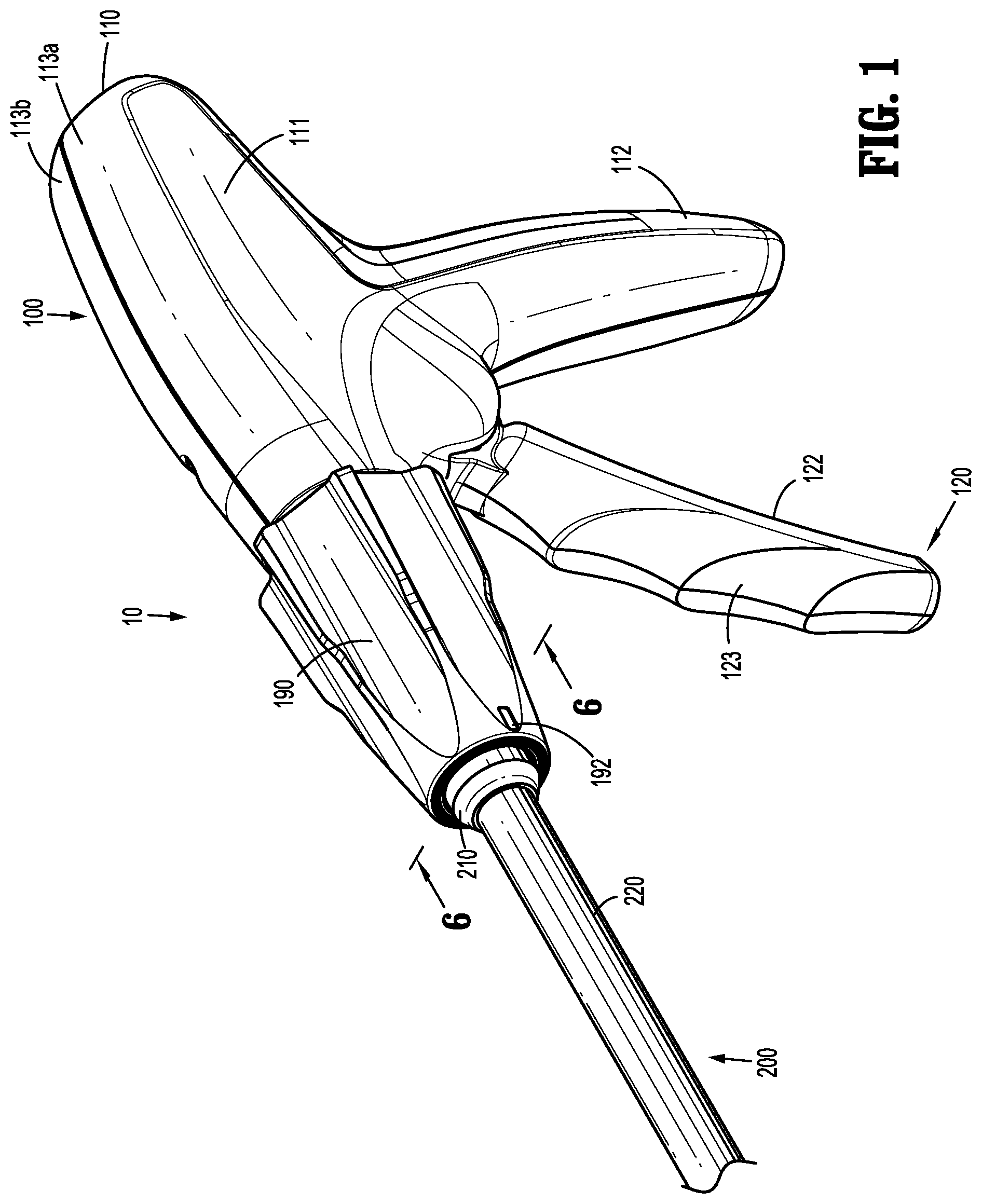
FIG. 1 is a perspective view of the proximal portion of an endoscopic surgical clip applier provided in accordance with the present disclosure including a handle assembly having an endoscopic assembly engaged therewith;
FIG. 2 is perspective view of the endoscopic surgical clip applier of FIG. 1 with the endoscopic assembly removed from the handle assembly;
FIG. 3 is an enlarged, perspective view of the area of detail indicated as "3" in FIG. 2;
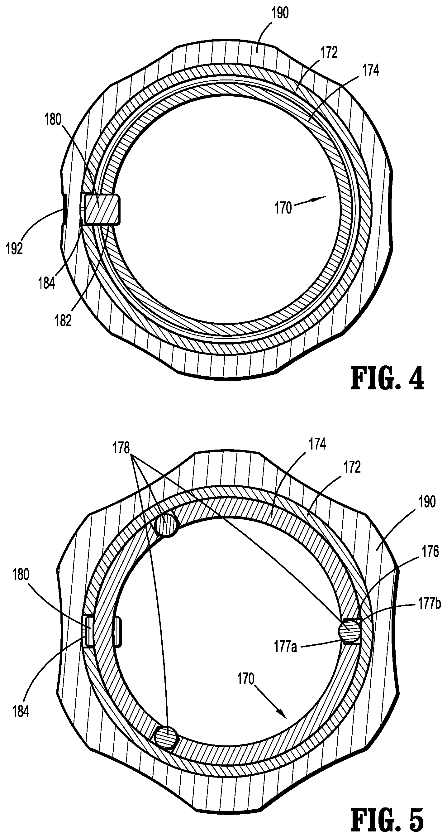
FIG. 4 is a transverse, cross-sectional view taken across section line 4-4 in FIG. 3;
FIG. 5 is a transverse, cross-sectional view taken across section line 5-5 in FIG. 3;
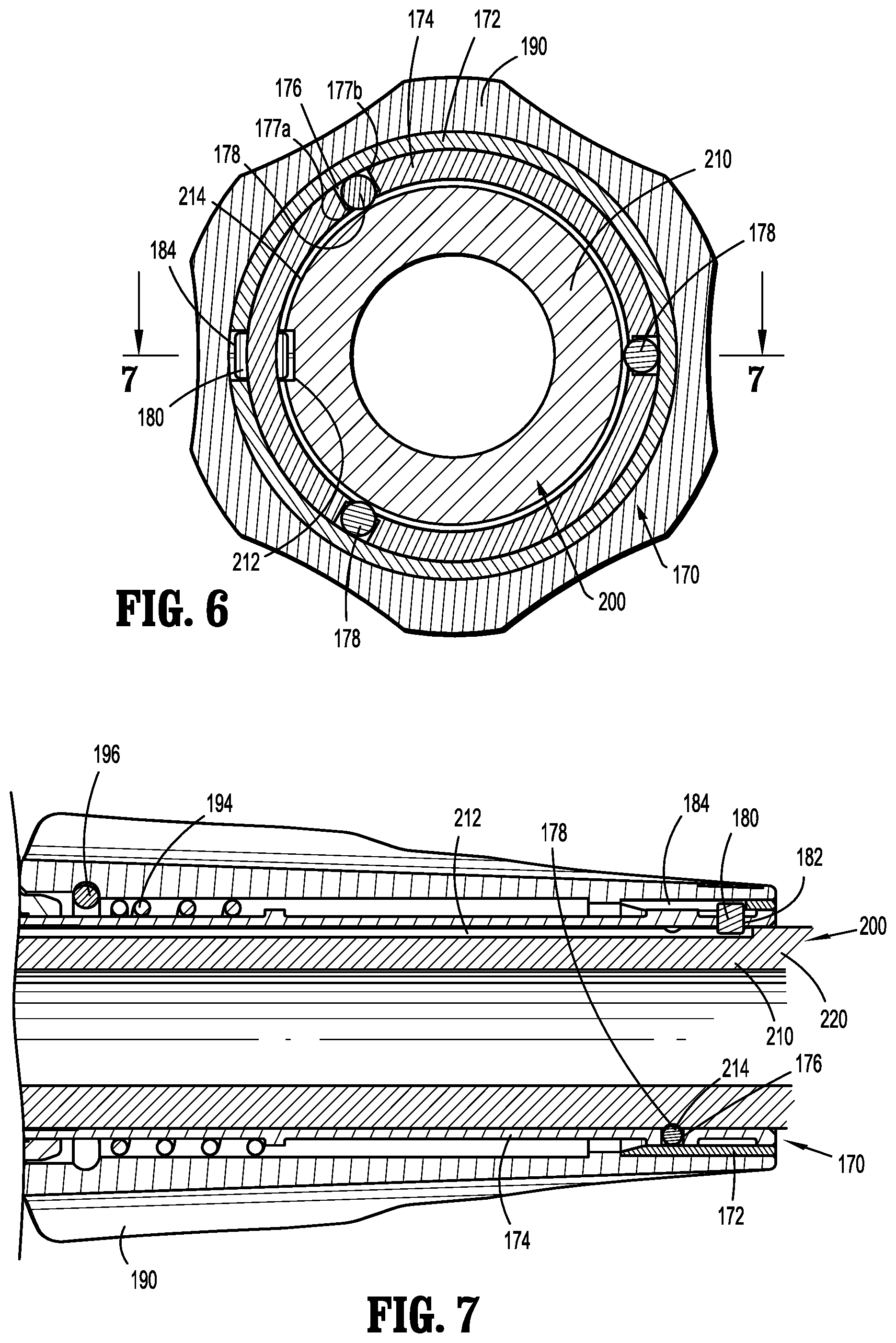
FIG. 6 is a transverse, cross-sectional view taken across section line 6-6 in FIG. 1;
FIG. 7 is a longitudinal, cross-sectional view taken across section line 7-7 in FIG. 6;
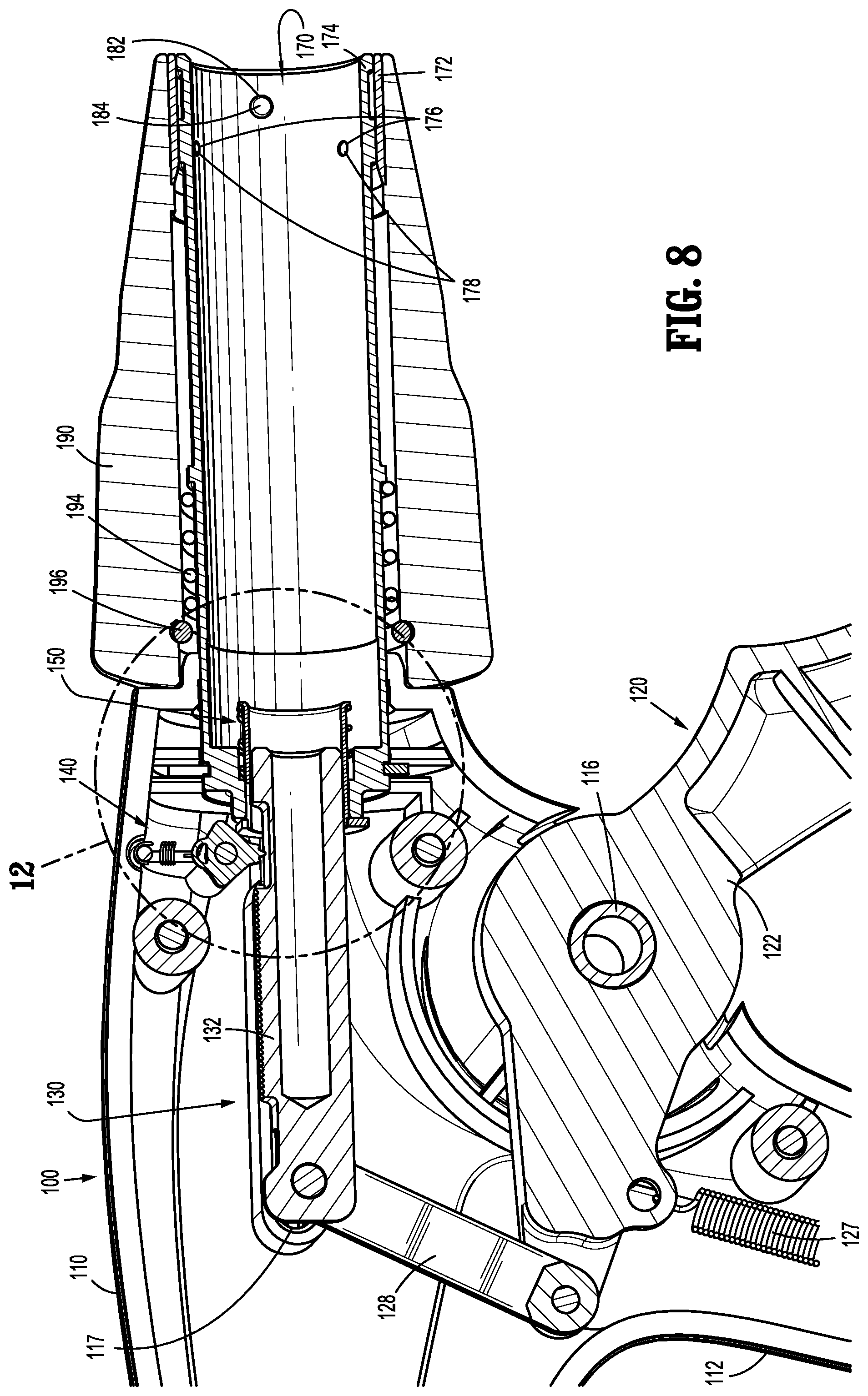
FIG. 8 is a longitudinal, cross-sectional view of handle assembly of FIG. 1;
FIG. 9 is an exploded view of the handle assembly of FIG. 1;
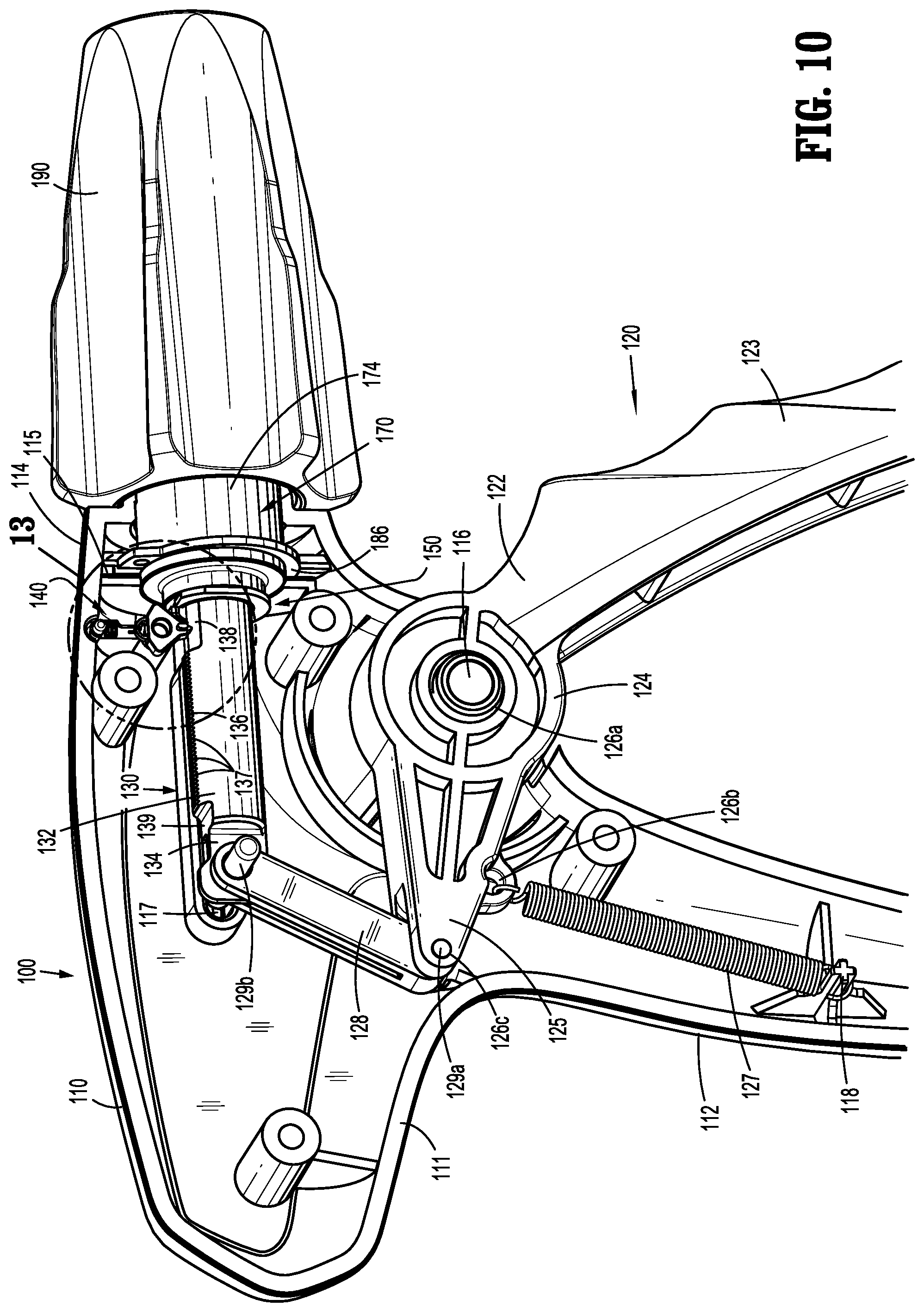
FIG. 10 is a perspective view of the handle assembly of FIG. 1 with a portion of the housing removed to illustrate the internal components therein;
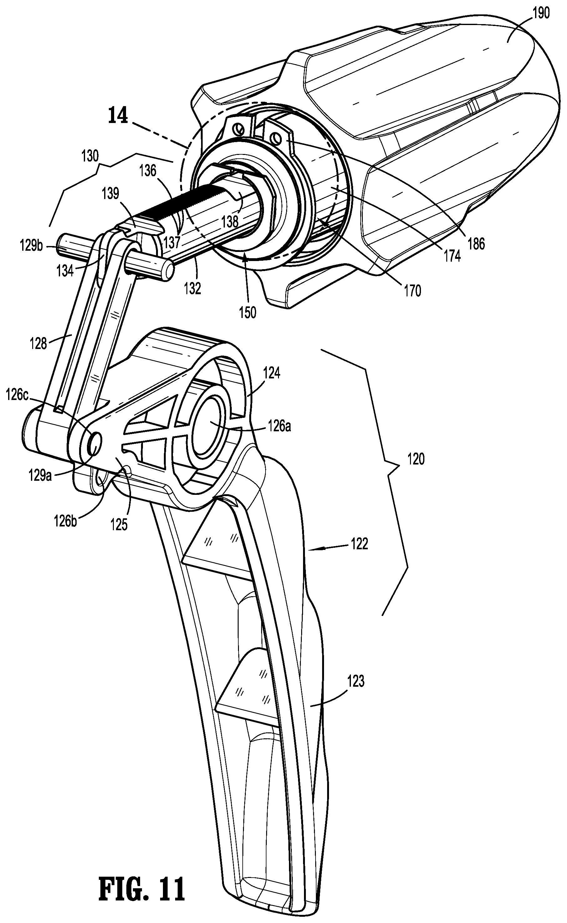
FIG. 11 is a perspective view of the internal assemblies of the handle assembly of FIG. 1;
FIG. 12 is an enlarged, longitudinal, cross-sectional view of the area of detail indicated as "12" in FIG. 8;
FIG. 13 is an enlarged, perspective view of the area of detail indicated as "13" in FIG. 10;
FIG. 14 is an enlarged, perspective view of the area of detail indicated as "14" in FIG. 11;
FIG. 15 is a perspective view of another endoscopic assembly configured for use with the handle assembly of FIG. 1;
FIG. 16 is an enlarged, perspective view of the distal portion of the endoscopic assembly of FIG. 15;
FIG. 17 is an enlarged, perspective view of the proximal portion of the endoscopic assembly of FIG. 15;
FIG. 18 is an enlarged, perspective, of the proximal portion of the endoscopic assembly of FIG. 15 with a portion of the outer housing shown in phantom to illustrate the internal components therein;
FIG. 19 is a longitudinal, cross-sectional view of the endoscopic assembly of FIG. 15;
FIG. 20 is an enlarged, longitudinal, cross-sectional view of the proximal portion of the endoscopic assembly of FIG. 15;
FIG. 21 is an enlarged, longitudinal, cross-sectional view illustrating the operable engagement between the handle assembly of FIG. 1 and the endoscopic assembly of FIG. 15;
FIG. 22 is a perspective view of another endoscopic assembly configured for use with the handle assembly of FIG. 1;
FIG. 23 is an enlarged, perspective view of the distal portion of the endoscopic assembly of FIG. 22;
FIG. 24 is an enlarged, perspective view of the proximal portion of the endoscopic assembly of FIG. 22;
FIG. 25 is an enlarged, perspective, of the proximal portion of the endoscopic assembly of FIG. 22 with a portion of the outer housing shown in phantom to illustrate the internal components therein;
FIG. 26 is a longitudinal, cross-sectional view of the endoscopic assembly of FIG. 22;
FIG. 27 is a longitudinal, cross-sectional view of the proximal portion of the endoscopic assembly of FIG. 22;
FIG. 28 is an enlarged, longitudinal, cross-sectional view illustrating the operable engagement between the handle assembly of FIG. 1 and the endoscopic assembly of FIG. 22;
FIG. 29 is a top, cross-sectional view illustrating an alternate embodiment of an endoscopic assembly provided in accordance with the present disclosure;
FIG. 30 is a perspective view of a handle assembly of an endoscopic assembly provided in accordance with another embodiment of the present disclosure;
FIG. 31 is a perspective, cut-away view of the handle assembly of FIG. 30;
FIG. 32 is a side, cut-away view of the handle assembly of FIGS. 30 and 31 shown in a first position;
FIG. 33 is a side, cut-away view of the handle assembly of FIGS. 30-32 shown in a second position;
FIG. 34 is a side, cut-away view of the handle assembly of FIGS. 30-33 shown in a third position; and
FIG. 35 is a graph illustrating the amount of force required to actuate a movable handle of the handle assembly of FIGS. 30-34 with respect to time; and
FIG. 36 is a schematic illustration of a robotic surgical system configured for use in accordance with the present disclosure.
DETAILED DESCRIPTION OF EMBODIMENTS
Turning to FIGS. 1 and 2, an endoscopic surgical clip applier provided in accordance with the present disclosure is identified by reference numeral 10. Surgical clip applier 10 generally includes a handle assembly 100 and a plurality of endoscopic assemblies 200 selectively connectable to and extendable distally from handle assembly 100. Handle assembly 100 is advantageously configured to operate each of the plurality of endoscopic assemblies 200, upon connection thereto, and may be configured as a sterilizable, reusable component such that handle assembly 100 may be repeatedly used with different and/or additional endoscopic assemblies 200 during the course of one or more surgical procedures. The endoscopic assemblies 200 may be configured as single-use disposable components, limited-use disposable components, or reusable components, depending upon a particular purpose and/or the configuration of the particular endoscopic assembly 200. In either configuration, the need for multiple handle assemblies 100 is obviated and, instead, the surgeon need only select an appropriate endoscopic assembly 200 and connect that endoscopic assembly 200 to handle assembly 100 in preparation for use.
Handle assembly 100 is initially detailed for use in connection with a generic endoscopic assembly 200 that includes features common to any endoscopic assembly usable with handle assembly 100. Exemplary embodiments of particular endoscopic assemblies, e.g., endoscopic assembly 300 (FIG. 15) and endoscopic assembly 400 (FIG. 22), are thereafter detailed below. Endoscopic assembly 300 (FIG. 15), for example, is configured for grasping and manipulating tissue, retrieving a surgical clip, and firing and forming the surgical clip about tissue. Endoscopic assembly 400 (FIG. 22), as another example, includes at least one surgical clip loaded therein and is configured to sequentially fire and form the at least one surgical clip about tissue. It is also envisioned that various other endoscopic assemblies for performing various different surgical tasks and/or having various different configurations may be provided for use with handle assembly 100.
Continuing with reference to FIGS. 1 and 2, as noted above, endoscopic assembly 200 is configured to selectively connect to and extend distally from handle assembly 100. Endoscopic assembly 200 includes a proximal hub 210 configured for insertion into and releasable engagement within handle assembly 100, an elongated shaft 220 extending distally from proximal hub 210, and an end effector assembly (not shown) disposed at the distal end of elongated shaft 220. Internal drive components (not shown) extend through proximal hub 210 and elongated shaft 220 so as to operably couple the end effector assembly (not shown) with handle assembly 100 upon engagement of endoscopic assembly 200 with handle assembly 100, e.g., to enable performing the one or more surgical tasks of the endoscopic assembly 200. Proximal hub 210 defines a generally tubular configuration and includes a longitudinally-extending slot 212 defined therein and an annular groove 214 defined therein. Longitudinally-extending slot 212 defines an open proximal end 213. Annular groove 214 extends circumferentially about proximal hub 210 and intersects longitudinally-extending slot 212, although other non-intersecting configurations are also contemplated.
Referring additionally to FIGS. 3-5, handle assembly 100 includes a receiver assembly 170 configured to receive proximal hub 210 of endoscopic assembly 200 and enable releasable engagement of endoscopic assembly 200 with handle assembly 100. Receiver assembly 170 includes an outer collar 172 and an inner tubular member 174. Inner tubular member 174 defines an interior diameter slightly larger than an exterior diameter of proximal hub 210 of endoscopic assembly 200 to enable slidable insertion of proximal hub 210 into inner tubular member 174 without significant play therebetween. Inner tubular member 174 further includes a plurality of apertures 176 defined therethrough and positioned circumferentially about inner tubular member 174. Apertures 176 define reduced interior openings 177a as compared to the exterior openings 177b thereof. A ball bearing 178 is disposed within each of the apertures 176. Although a portion of each ball bearing 178 protrudes inwardly through the reduced interior opening 177a of its respective aperture 176, the reduced interior openings 177a inhibit ball bearings 178 from passing entirely therethrough. Outer collar 172 is positioned so as to block the exterior openings 177b of apertures, thereby retaining ball bearings 178 within apertures 176 between outer collar 172 and the reduced interior openings 177a (except for the portions of ball bearings 178 extending through the reduced interior openings 177a).
A pin 180 extends through a pin aperture 182 defined within inner tubular member 174 and at least partially through a pin slot 184 defined within outer collar 172. Pin 180 extends at least partially into the interior of inner tubular member 174 and, as detailed below, is configured to facilitate alignment of endoscopic assembly 200 upon insertion of endoscopic assembly 200 into handle assembly 100. Pin 180 is further configured to retain outer collar 172 and inner tubular member 174 in fixed rotational orientation relative to one another. Outer collar 172 is engaged with rotation knob 190 of handle assembly 100 in fixed rotational orientation such that, with pin 180 rotatably coupling outer collar 172 and inner tubular member 174, rotation of rotation knob 190 can be effected to similarly rotate receiver assembly 170. Rotation knob 190 includes an alignment indicator 192 disposed thereon that is aligned with pin 180 to enable alignment of endoscopic assembly 200 with receiver assembly 170 without the need to directly view the position of pin 180.
With reference to FIGS. 1, 2, 6 and 7, in order to engage endoscopic assembly 200 with handle assembly 100, endoscopic assembly 200 is oriented such that longitudinally-extending slot 212 thereof is aligned with pin 180 of receiver assembly 170. As noted above, rather than having to view pin 180 directly, alignment of longitudinally-extending slot 212 and pin 180 can be achieved via aligning longitudinally-extending slot 212 with alignment indicator 192 of rotation knob 190 of handle assembly 100. Once alignment has been achieved, proximal hub 210 of endoscopic assembly 200 is slid proximally into inner tubular member 174 of receiver assembly 170. Alignment of longitudinally-extending slot 212 and pin 180 ensures that, upon proximal sliding of proximal hub 210 into inner tubular member 174, pin 180 is translated through longitudinally-extending slot 212.
As proximal hub 210 is slid proximally into inner tubular member 174, ball bearings 178 apply radially-inward force on the exterior of proximal hub 210 causing proximal hub 210, outer collar 172, inner tubular member 174, and/or ball bearings 178 to move or flex to accommodate proximal hub 210 between ball bearings 178. Ball bearings 178 are permitted to rotate within apertures 176 as proximal hub 210 is slid proximally into inner tubular member 174, reducing friction and permitting relatively easy sliding of proximal hub 210 into inner tubular member 174. Upon full insertion of proximal hub 210 into inner tubular member 174, e.g., upon pin 180 reaching the closed, distal end of longitudinally-extending slot 212, ball bearings 178 are moved into position about annular groove 214. As a result of the radially-inward force imparted by ball bearings 178, once the fully inserted position has been achieved, ball bearings 178 are urged into annular groove 214 to thereby releasably lock proximal hub 210 of endoscopic assembly 200 in engagement within receiver assembly 170 of handle assembly 100. The operable coupling of endoscopic assembly 200 with handle assembly 100 to enable operation thereof to perform one or more surgical tasks depends upon the type of endoscopic assembly 200 engaged with handle assembly 100 and will be detailed below with respect to exemplary endoscopic assemblies 300 (FIG. 15) and 400 (FIG. 22).
In order to remove endoscopic assembly 200 from handle assembly 100, endoscopic assembly 200 is pulled distally relative to handle assembly 100 under sufficient urging so as to dislodge ball bearings 178 from annular groove 214, thus permitting proximal hub 210 of endoscopic assembly 200 to be slid distally out of receiver assembly 170 of handle assembly 100.
Referring to FIGS. 1, 2, and 8-10, handle assembly 100 generally includes a housing 110, a trigger assembly 120 pivotably coupled to housing 110, a ratcheting drive assembly 130 operably coupled to trigger assembly 120, a bypass assembly 150 operably coupled to ratcheting drive assembly 130, receiver assembly 170 which extends distally from housing 110, and rotation knob 190 which is operably disposed about receiver assembly 170.
Housing 110 defines a body portion 111 and a fixed handle portion 112 extending downwardly from body portion 111. Housing 110 is formed from first and second housing components 113a, 113b secured to one another via pin-post engagement, although first and second housing components 113a, 113b may alternatively be secured in any other suitable manner, e.g., ultrasonic welding, gluing, other mechanical engagement, etc. Housing 110 is configured to house the internal working components of handle assembly 100. Body portion 111 includes a distal nose 114 defining an annular slot 115 on the interior thereof. More specifically, first and second housing components 113a, 113b each define a semi-annular slot portion such that, when first and second housing components 113a, 113b cooperate to form housing 110, annular slot 115 is formed. Receiver assembly 170 of handle assembly 100 includes a retention clip 186 disposed about the proximal end of inner tubular member 174 thereof. Retention clip 186 is captured within annular slot 115 defined within distal nose 114 of housing 110, e.g., upon engagement of first and second housing components 113a, 113b with one another. Retention clip 186 is captured within annular slot 115 to rotatably engage receiver assembly 170 with housing 110. Rotation knob 190 of handle assembly 100 is operably engaged about receiver assembly 170, e.g., via outer collar 172, biasing member 194, and elastomeric C-ring 196, in fixed rotational orientation relative thereto such that rotation of rotation knob 190 relative to housing 110 effects similar rotation of receiver assembly 170 relative to housing 110. Thus, with endoscopic assembly 200 engaged within receiver assembly 170, rotation knob 190 may be rotated relative to housing 100 to similarly rotate endoscopic assembly 200 relative to housing 110.
Body portion 111 of housing 110 further includes an internal pivot post 116 extending transversely between housing components 113a, 113b and a longitudinally-extending guide track 117 defined within one or both of housing components 113a, 113b, the importance of each of which is detailed below. Fixed handle portion 112 of housing 110 is configured to facilitate grasping of handle assembly 100 and manipulation thereof and is monolithically formed with body portion 111, although other configurations are also contemplated.
With additional reference to FIG. 11, trigger assembly 120 generally includes a trigger 122, a biasing member 127, and a linkage 128. Trigger 122 includes a grasping portion 123, an intermediate pivot portion 124, and a proximal extension portion 125. Grasping portion 123 of trigger 122 extend downwardly from body portion 111 of housing 110 in opposed relation relative to fixed handle portion 112 of housing 110. Grasping portion 123 is configured to facilitate grasping and manipulation of trigger 122. Intermediate pivot portion 124 of trigger 122 is at least partially disposed within housing 110 and defines a pivot aperture 126a that is configured to receive pivot post 116 of housing 110 so as to enable pivoting of trigger 122 about pivot post 116 and relative to housing 110, e.g., between an un-actuated position, wherein grasping portion 123 of trigger 122 is spaced-apart relative to fixed handle portion 112, and an actuated position, wherein grasping portion 123 of trigger 122 is approximated relative to fixed handle portion 112.
Proximal extension portion 125 of trigger 122 of trigger assembly 120 is disposed on an opposite side of intermediate pivot portion 124 and, thus, pivot post 116, as compared to grasping portion 123 of trigger 122. As such, pivoting of grasping portion 123 proximally, e.g., towards the actuated position, urges proximal extension portion 125 distally. Proximal extension portion 125 includes a first aperture 126b configured to receive a first end of biasing member 127, and a pair of second apertures 126c configured to receive a first pin 129a for pivotably coupling the proximal end of linkage 128 and proximal extension portion 125 of trigger 122 with each other. The second end of biasing member 127 is engaged about an arm 118 extending transversely within fixed handle portion 112. Biasing member 127 is disposed in an at-rest condition in the un-actuated position of grasping portion 123 of trigger 122. Pivoting of grasping portion 123 towards the actuated position elongates biasing member 127 storing energy therein such that, upon release of grasping portion 123, grasping portion 123 is returned towards the un-actuated position under the bias of biasing member 127. Although illustrated as an extension coil spring, biasing member 127 may define any suitable configuration for biasing grasping portion 123 of trigger 122 towards the un-actuated position.
As noted above, linkage 128 is coupled at its proximal end to proximal extension portion 125 of trigger 122 via first pin 129a. Linkage 128 is also pivotably coupled, at its distal end, to proximal extension 134 of drive bar 132 of ratcheting drive assembly 130 via a second pin 129b. Second pin 129b extends outwardly from either or both sides of proximal extension 134 of drive bar 132 and is received within the longitudinally-extending guide track(s) 117 defined within housing component 113a and/or housing component 113b. As a result of this configuration, pivoting of grasping portion 123 towards the actuated position urges proximal extension portion 125 distally which, in turn, urges linkage 128 distally such that second pin 129b is translated distally through longitudinally-extending guide track(s) 117.
Continuing with reference to FIGS. 1, 2, and 8-11, ratcheting drive assembly 130 of handle assembly 100 includes a drive bar 132 and a pawl assembly 140. Drive bar 132 includes a proximal extension 134, a ratchet rack 136, and distal and proximal recesses 138, 139, respectively. Proximal extension 134 is disposed at the proximal end of the drive bar 132 and defines an aperture 135 configured to receive second pin 129b of trigger assembly 120 so as to pivotably couple the distal end of linkage 128 and drive bar 132 with one another, as noted above. As such, upon pivoting of grasping portion 123 towards the actuated position to urge second pin 129b distally through longitudinally-extending guide track(s) 117, drive bar 132 is translated distally through body portion 111 of housing 110. Ratchet rack 136 of drive bar 132 defines a plurality of teeth 137 and extends longitudinally along drive bar 132 on an upper surface thereof. Distal and proximal recesses 138, 139 are defined by cut-outs formed in drive bar 132 and are positioned distally adjacent ratchet rack 136 and proximally adjacent ratchet rack 136, respectively.
Referring also to FIG. 12, pawl assembly 140 of ratcheting drive assembly 130 includes a ratchet pawl 142, a pawl pin 144, and a pawl biasing member 146. Ratchet pawl 142 is pivotably coupled to body portion 111 of housing 110 by pawl pin 144 so as to enable operable engagement of ratchet pawl 142 with ratchet rack 136 when an endoscopic assembly 200 that uses the ratcheting function is connected to handle assembly 100, and to enable pivoting of ratchet pawl 142 to a bypass position when a endoscopic assembly 200 that does not use the ratcheting function is connected to handle assembly 100. Ratchet pawl 142 further includes a pair of outwardly-extending tabs 143 extending transversely from either side thereof, the importance of which are detailed below.
Pawl biasing member 146 of pawl assembly 140 is coupled between ratchet pawl 142 and body portion 111 of housing 110 so as to bias ratchet pawl 142 towards a use position and away from the bypass position. In the use position, ratchet pawl 142 is oriented to operably engage ratchet rack 136 upon distal advancement of drive bar 132. However, in the proximal-most position of drive bar 132, corresponding to the un-actuated position of trigger 122, ratchet pawl 142 is disposed at least partially within distal recess 138 of drive bar 132. Accordingly, at least initially, ratchet pawl 142 is disengaged from ratchet rack 136.
With reference to FIGS. 8-14, bypass assembly 150 is operably positioned between pawl assembly 140 and receiver assembly 170 and is configured, in response to engagement of handle assembly 100 with an endoscopic assembly 200 that does not use the ratcheting function, to pivot ratchet pawl 142 to the bypass position, thereby inhibiting ratcheting upon advancement of drive bar 132. When an endoscopic assembly 200 that uses the ratcheting function is connected to handle assembly 100, bypass assembly 150 remains idle such that ratchet pawl 142 remains in the use position to enable ratcheting of ratchet pawl 142 along ratchet rack 136 upon advancement of drive bar 132.
Bypass assembly 150 includes a sleeve 152, a biasing member 154, and a camming clip 156. Sleeve 152 extends into the proximal end of inner tubular member 174 of receiver assembly 170 and is disposed about the distal end of drive bar 132 of drive assembly 130 in slidable relation relative to both inner tubular member 174 and drive bar 132. Biasing member 154 is disposed within inner tubular member 174 of receiver assembly 170 and about sleeve 152. More specifically, biasing member 154 is retained about sleeve 152 between a distal rim 153 of sleeve 152 and an annular shoulder 179 defined within the interior of inner tubular member 174 at the proximal end thereof. As a result of this configuration, biasing member 154 biases sleeve 152 proximally into the interior of inner tubular member 174. Distal rim 153 of sleeve 152 is radially-spaced from the interior wall defining inner tubular member 174 so as to define an annular spacing "A1" therebetween. Sleeve 152 further defines an internal diameter "D1."
Camming clip 156 of bypass assembly 150 is engaged within an annular groove 157 defined about the exterior of sleeve 152 towards the proximal end thereof. Camming clip 156 is sufficiently dimensioned so as to inhibit passage into the interior of inner tubular member 174 and, thus, inhibits sleeve 152 from fully entering inner tubular member 174 under the bias of biasing member 154. Camming clip 156 further include a pair of opposed, inwardly extending fingers 158 at the free ends thereof. Fingers 158 are positioned such that, upon sufficient proximal urging of sleeve 152 against the bias of biasing member 154, fingers 158 contact respective tabs 143 of ratchet pawl 142. Thus, upon further proximal movement of sleeve 152, fingers 158 urge respective tabs 143 proximally, ultimately such that ratchet pawl 142 is urged to rotate about pawl pin 144 and against the bias of pawl biasing member 146 from the use position to the bypass position.
Turning to FIGS. 15-21, and endoscopic assembly 300 provided in accordance with the present disclosure and configured for use with handle assembly 100 is shown. Endoscopic assembly 300 is configured for non-ratcheting use and, thus, upon engagement of endoscopic assembly 300 with handle assembly 100, as detailed below, ratchet pawl 142 is pivoted to and retained in the bypass position, thus enabling such non-ratcheting use. Endoscopic assembly 300 generally includes a proximal hub 310, an inner drive assembly 320 disposed within and extending through proximal hub 310, an elongated shaft 340 extending distally from proximal hub 310, and an end effector assembly 350 including a pair of jaw members 360a, 360b disposed at the distal end of elongated shaft 340. Endoscopic assembly 300 is configured to grasp and/or manipulate tissue, retrieve a surgical clip, and to close, fire, or form the surgical clip about tissue. It is contemplated that endoscopic assembly 300 be configured to close, fire or form surgical clips similar to those shown and described in U.S. Pat. No. 4,834,096, the entire contents of which are incorporated herein by reference.
With additional reference to FIGS. 1, 2, 6, and 7, proximal hub 310 of endoscopic assembly 300 defines a generally tubular configuration and an exterior diameter slightly smaller than that of inner tubular member 174 of receiver assembly 170 of handle assembly 100 to enable slidable insertion of proximal hub 310 into inner tubular member 174 without significant play therebetween. Proximal hub 310 further includes features similar to those detailed above with respect to endoscopic assembly 200 so as to enable engagement of proximal hub 310 within receiver assembly 170 of handle assembly 100 in a similar fashion. More specifically, proximal hub 310 a longitudinally-extending slot 311 configured to receive pin 180 of receiver assembly 170 to ensure proper alignment of endoscopic assembly 300 relative to handle assembly 100, and an annular groove 312 configured to receive at least a portion of each ball bearing 178 to releasably lock proximal hub 310 of endoscopic assembly 300 in engagement within receiver assembly 170 of handle assembly 100.
Referring again to FIGS. 15-21, proximal hub 310 of endoscopic assembly 300 further defines an internal bore 313 having an open proximal end 314 and a reduced-diameter distal opening as compared to the diameter of bore 313 so as to define a shoulder 315 therebetween. A ferrule 316 is seated within the open proximal end of proximal hub 310 and secured therein in any suitable fashion, e.g., welding, gluing, press-fitting, mechanical engagement, etc.
Ferrule 316 of proximal hub 310 defines an aperture 317 extending longitudinally therethrough and a proximally-facing surface 318 surrounding aperture 317 such that proximally-facing surface 318 defines a ring-shaped configuration. Aperture 317 is disposed in communication with the interior of proximal hub 310 so as to provide access to inner drive assembly 320, as detailed below, and defines a diameter "D2" that is sufficiently large so as to permit slidable insertion of drive bar 132 of ratcheting drive assembly 130 of handle assembly 100 therethrough. However, diameter "D2" of aperture 317 is smaller than internal diameter "D1" of sleeve 152. Proximally-facing surface 318 of ferrule 316 defines an annular width "A2" that is larger than the annular spacing "A1" defined between distal rim 153 of sleeve 152 and the interior wall defining inner tubular member 174. As a result of diameter "D2" being smaller than diameter "D1" and annular width "A2" being larger than annular spacing "A1," proximal hub 310 is inhibited from passing into the interior of sleeve 152 and is likewise inhibited from passing about the exterior of sleeve 152. Rather, upon proximal urging of proximal hub 310 of endoscopic assembly 300 into inner tubular member 174 of receiver assembly 170 of handle assembly 100, e.g., to engage endoscopic assembly 300 with handle assembly 100, proximally-facing surface 318 of ferrule 316 eventually contacts distal rim 153 of sleeve 152 such that further proximal urging of proximal hub 310 into inner tubular member 174 urges sleeve 152 proximally against the bias of biasing member 154.
As noted above, endoscopic assembly 300 is configured for non-ratcheting use. Accordingly, the above-detailed configuration regarding the relative dimensions of the components of proximal hub 310 and those of bypass assembly 150 ensures that proximal hub 310 urges ratchet pawl 142 from the use position to the bypass position upon engagement of endoscopic assembly 300 with handle assembly 100, thus disabling the ratcheting components of ratcheting drive assembly 130. More specifically, with pin 180 received within longitudinally-extending slot 311 and proximal hub 310 sliding proximally into inner tubular member 174 of receiver assembly 170, but prior to engagement of ball bearings 178 within annular groove 312, proximally-facing surface 318 of ferrule 316 contacts distal rim 153 of sleeve 152 and urges sleeve 152 proximally such that fingers 158 of camming clip 156 urge tabs 143 of ratchet pawl 142 proximally to thereby rotate ratchet pawl 142 about pawl pin 144 from the use position towards the bypass position. Accordingly, upon reaching the engaged position of proximal hub 310 within inner tubular member 174, e.g., upon engagement of ball bearings 178 within annular groove 312, as shown in FIG. 21, ferrule 316 has urged sleeve 152 to a proximal-most position wherein ratchet pawl 142 is pivoted to and retained in the bypass position. Thus, when endoscopic assembly 300 is engaged with handle assembly 100, ratcheting of ratcheting drive assembly 130 is disabled.
Referring still to FIGS. 15-21, inner drive assembly 320 of endoscopic assembly 300 includes an inner shaft 322 slidably disposed within both proximal hub 310 and elongated shaft 340 of endoscopic assembly 300. Inner shaft 322 includes a proximal end 323 supporting a transverse pin 324 disposed within bore 313 of proximal hub 310, and a distal end 325 supporting a cam pin 326 disposed towards the distal end 344 of elongated shaft 340. As detailed below, cam pin 326 is disposed within cam slots (not shown) of jaw members 360a, 360b of end effector assembly 350 to enable pivoting of jaw members 360a, 360b between open and closed positions in response to translation of inner shaft 322 through elongated shaft 340.
Inner drive assembly 320 further includes a plunger 328 and first and second biasing members 330, 332, respectively. Plunger 328 is slidably disposed within bore 313 of proximal hub 310 and is retained therein between shoulder 315 and ferrule 316. Plunger 328 defines an internal cavity 329 within which transverse pin 324 of proximal end 323 of inner shaft 322 is slidably confined.
First biasing member 330 of inner drive assembly 320 is disposed within internal bore 313 of proximal hub 310 and interposed between shoulder 315 of proximal hub 310 and transverse pin 324 of inner shaft 322. First biasing member 330 has a first spring constant "K1" which is less than a second spring constant "K2" of second biasing member 332, the importance of which is detailed below. Second biasing member 332 is disposed within cavity 329 of plunger 328 and is interdisposed between transverse pin 324 of inner shaft 322 and the proximal end of plunger 328. As detailed below, first and second biasing members 330, 332, respectively, facilitate appropriate translation of inner shaft 322 through proximal hub 310 and elongated shaft 340 to open and close jaw members 340a, 340b, and to enable full actuation of trigger 122 (FIG. 1), as detailed below.
Elongated shaft 340 of endoscopic assembly 300 defines a generally tubular configuration and extends between and interconnects proximal hub 310 and end effector assembly 350. More specifically, the proximal end 342 of elongated shaft 340 is secured to proximal hub 310, while the distal end 344 of elongated shaft 340 supports a clevis 346 configured to pivotably engage jaw members 360a, 360b of end effector assembly 350 at distal end 344 of elongated shaft 340 via a pivot pin 352.
End effector assembly 350, as noted above, includes first and second jaw members 360a, 360b. Jaw members 360a, 360b are pivotably engaged to one another and clevis 346 via pivot pin 352 so as to permit pivoting of jaw members 360a, 360b relative to one another and elongated shaft 340 between an open position and a closed position. Each jaw member 360a, 360b includes a respective proximal end 361a, 361b and a respective distal end 362a, 362b. The proximal end 361a, 361b of each jaw member 360a, 360b defines the cam slots (not shown) that are configured to receive cam pin 326 of inner shaft 322 such that translation of inner shaft 322 pivots jaw members 360a, 360b between the open and closed positions. The distal ends 362a, 362b of jaw members 360a, 360b are configured to receive and close, fire or form a surgical clip, e.g., a surgical clip similar to those shown and described in U.S. Pat. No. 4,834,096, previously incorporated herein by reference.
Referring momentarily to FIG. 29, an alternate embodiment of inner drive assembly 320 is illustrated. In this embodiment, inner shaft 322 of endoscopic assembly 300 is divided into a proximal portion 322' and a distal portion 322''. A proximal end 322a'' of distal portion 322'' includes a bore 322b'' defined therein configured to slidably receive an elongate member 322b' disposed on a distal end 322a' of proximal portion 322'. A transverse slot 322c'' is defined through distal portion 322'' of inner shaft 322 and is configured to slidably retain a transverse pin 320a'. Transverse pin 320a' is fixedly retained within an aperture (not shown) defined in the distal end 322a' of proximal portion 322' using any suitable means, such as friction fit, welding, adhesives, or the like. A biasing member 320b' is disposed between proximal portion 322' and distal portion 322'' of inner shaft 322 and acts upon proximal end 322a'' of distal portion 322'' and an annular surface 322c' disposed on a distal end 322a' of proximal portion 322'. In this manner, biasing member (e.g., a spring or the like) 320b' is initially compressed such that proximal portion 322' and distal portion 322'' are maintained in spaced relation. Transverse pin 320a' inhibits proximal portion 322' and distal portion 322'' from being urged apart by biasing member 320b' as transverse pin 320b' is at a proximal most position in the stroke of transverse slot 322c''.
In operation, if the closure of the jaw members 360a, 360b should become stuck or otherwise prevented from closing completely (e.g., where the jaw members 360a, 360b are closing onto bone or onto another surgical clip), this over-load compensation system permits a forward stroke of ratcheting drive assembly 130 of handle assembly 100 may be fully completed (wherein a distal driving force of proximal portion 322' of inner shaft 322 axially compresses biasing member 320b' having a spring constant "K3", which is greater than that of "K1" or "K2") in order to permit a re-set or a reversal of ratcheting drive assembly 130 and permit trigger 122 to open.
The use of handle assembly 100 in conjunction with endoscopic assembly 300 is now detailed with reference to FIGS. 8-21. Initially, endoscopic assembly 300 is engaged with handle assembly 100, as detailed above. Such engagement of endoscopic assembly 300 with handle assembly 100, as also detailed above, effects pivoting of ratchet pawl 142 to and retention of ratchet pawl 142 in the bypass position. Once endoscopic assembly 300 and handle assembly 100 are engaged with ratchet pawl 142 in the bypass position, handle assembly 100 and endoscopic assembly 300 are together ready for use.
In use, trigger 122 is initially disposed in the un-actuated position under the bias of biasing member 127. With trigger 122 disposed in the un-actuated position, drive bar 132 is disposed in a proximal-most position. Further, inner shaft 322 is disposed in a proximal-most position under the bias of first and second biasing members 330, 332. Thus, jaw members 360a, 360b, initially, are disposed in the open position. With jaw members 360a, 360b disposed in the open position, a new, unformed or open surgical clip (not shown) may be located or loaded within the distal ends 362a, 362b of jaw members 360a, 360b. Jaw members 360a, 360b of end effector assembly 350 may be used to retrieve or pick-up a surgical clip from a clip holder (not shown), the surgical clip may be manually loaded by the user, end effector assembly 350 may be pre-loaded by the manufacturer, or the surgical clip may be placed between jaw members 360a, 360b in any other suitable fashion.
In or to close, fire, or form the surgical clip loaded between jaw members 360a, 360b, trigger 122 is urged from the un-actuated position to the actuated position. More specifically, grasping portion 123 of trigger 122 is pivoted towards fixed handle portion 112 of housing 110 to urge linkage 128 distally which, in turn, urges drive bar 132 distally through housing 110, receiver assembly 170, and into bore 313 of proximal hub 310 of endoscopic assembly 300. As trigger 122 is pivoted further towards the actuated position, drive bar 132 eventually contacts plunger 328 of drive assembly 320 of endoscopic assembly 300. Due to first spring constant "K1" of first biasing member 330 being less than second spring constant "K2" of second biasing member 332, as drive bar 132 is initially urged into plunger 328, plunger 328 and inner shaft 322 translate together distally such that first biasing member 330 is compressed while second biasing member 332 remains substantially un-compressed.
As inner shaft 322 is translated distally, cam pin 326 is translated through the cam slots of jaw members 360a, 360b to pivot jaw members 360a, 360b towards the closed position to close and/or form the surgical clip (not shown) loaded within end effector assembly 350. Cam pin 326 is advanced distally until cam pin 326 reaches an end of the cam slots of jaw members 360a, 360b and/or until jaw members 360a, 360b are fully approximated against one another or fully closed on the surgical clip. As can be appreciated, depending upon the particular endoscopic assembly used, the configuration of the surgical clip being formed, and/or other factors, the required travel distance of inner shaft 322 to fully form the surgical clip may vary. As the distance of travel for trigger 122 between the un-actuated and actuated positions does not vary, it is endoscopic assembly 300 that accounts for this variation, as detailed below.
Once jaw members 360a, 360b have been fully approximated against one another or fully closed on the surgical clip, and/or when cam pin 326 has reached the end of the cam slots of jaw members 360a, 360b, inner shaft 322 is no longer permitted to travel further distally. Thus, upon further distal urging of drive bar 132, e.g., to complete the actuation stroke of trigger 122, plunger 328 is advanced distally independently of inner shaft 322 to compress second biasing member 332. Thus, the compression of second biasing member 332 enables inner shaft 322 to remain in position while the full actuation stroke of trigger 122 is completed.
Once the surgical clip has been fully formed, trigger 122 may be released and allowed to return under bias to the un-actuated position, thereby pulling drive bar 132 back to its proximal-most position and allowing jaw members 360a, 360b to return to the open position. Thereafter, the above-detailed use may be repeated to close, fire, or form additional surgical clips. Additionally or alternatively, jaw members 360a, 360b of end effector assembly 350 may be used to grasp and/or manipulate tissue as desired prior to or after formation of one or more surgical clips.
Turning to FIGS. 22-28, another endoscopic assembly 400 provided in accordance with the present disclosure and configured for use with handle assembly 100 (FIG. 1) is shown. Endoscopic assembly 400 is configured for ratcheting use and, thus, upon engagement of endoscopic assembly 400 with handle assembly 100, as detailed below, ratchet pawl 142 remains in the use position to enable ratcheting use. Endoscopic assembly 400 generally includes a proximal hub 410, an elongated shaft 420 extending distally from proximal hub 410, a drive assembly 430 disposed within proximal hub 410 and elongated shaft 420, and a pair of jaw members 460a, 460b supported at the distal end of elongated shaft 420. Endoscopic assembly 400 is configured to close, fire, or form one or more surgical clips about tissue. More specifically, it is contemplated that endoscopic assembly 400 may be configured to close, fire or form surgical clips similar to those shown and described in U.S. Pat. No. 7,819,886 or 7,905,890, the entire contents of each of which is incorporated herein by reference.
With reference also to FIGS. 1, 2, 6, and 7, proximal hub 410 further includes features similar to those detailed above with respect to endoscopic assembly 200 so as to enable engagement of proximal hub 410 within receiver assembly 170 of handle assembly 100 in a similar fashion. More specifically, proximal hub 410 a longitudinally-extending slot 411 configured to receive pin 180 of receiver assembly 170 to ensure proper alignment of endoscopic assembly 400 relative to handle assembly 100, and an annular groove 412 configured to receive at least a portion of each ball bearing 178 to releasably lock proximal hub 410 of endoscopic assembly 400 in engagement within receiver assembly 170 of handle assembly 100.
As noted above, endoscopic assembly 400 is configured for ratcheting use and, thus, upon engagement of endoscopic assembly 400 with handle assembly 100 ratchet pawl 142 remains in the use position to enable ratcheting use. To allow such, proximal hub 410 defines a ring-shaped aperture 414 annularly disposed between the outer housing defining proximal hub 410 and plunger 435 of drive assembly 430, which is slidably disposed within proximal hub 410. This ring-shaped aperture 414 is positioned and dimensioned to receive distal rim 153 of sleeve 152 upon insertion of endoscopic assembly 400 into receiver assembly 170. Thus, upon insertion of proximal hub 410 of endoscopic assembly 400 into inner tubular member 174 of receiver assembly 170 of handle assembly 100, e.g., to engage endoscopic assembly 400 with handle assembly 100, distal rim 153 of sleeve 152 passes into proximal hub 410 through ring-shaped aperture 414 undisturbed such that sleeve 152 is maintained in its distal-most position under the bias of biasing member 154. With sleeve 152 in its distal-most position, ratchet pawl 142 remains in the use position, thus enabling ratcheting use of ratcheting drive assembly 130 of handle assembly 100.
Referring back to FIGS. 22-28, as mentioned above, endoscopic assembly 400 includes an elongated shaft 420 extending distally from proximal hub 410. Elongated shaft 420 includes a proximal end 422 secured to proximal hub 410 and a distal end 424 supporting first and second jaw members 460a, 460b.
Drive assembly 430 includes an inner shaft 431 slidably supported within the interior of elongated shaft 420 and proximal hub 410. Inner shaft 431 includes a proximal end 433 and a distal end 434. The proximal end 433 of inner shaft 431 extends into internal bore 413 of proximal hub 410 and is operably coupled to plunger 435 of drive assembly 430 via receipt of transverse pin 436 of inner shaft 431 within longitudinal slots 437 of plunger 435. Distal end 434 of inner shaft 431 is configured to transition first and second jaw members 460a, 460b from an open position to a closed position to form a surgical clip (not shown) that has been loaded into first and second jaw members 460a, 460b in response to distal translation of inner shaft 431 through elongated shaft 420.
It is contemplated that inner shaft 431 may be split into a proximal portion and a distal portion in a similar manner as disclosed above with respect to inner shaft 322. The components and operation of this embodiment of inner shaft 431 are similar to that of inner shaft 322, and therefore, a detailed description of the components and operation thereof will not be described hereinbelow.
Drive assembly 430 further includes a stop ring 438 and first and second biasing members 439a, 439b, each of which is disposed about inner shaft 431. Stop ring 438 is fixedly engaged about inner shaft 431 and disposed within internal bore 413 of proximal hub 410. First biasing member 439a is positioned distally of stop ring 438 and is retained between stop ring 438 and the distal end of proximal hub 410. Second biasing member 439b is positioned proximally of stop ring 438 and is retained between stop ring 438 and the distal end of plunger 435. First biasing member 439a has a first spring constant "KK1" which is less than a second spring constant "KK2" of second biasing member 439b, the importance of which is detailed below.
The use of handle assembly 100 in conjunction with endoscopic assembly 400 is now detailed with reference to FIGS. 8-14 and 22-28. Initially, endoscopic assembly 400 is engaged with handle assembly 100, as detailed above. Since endoscopic assembly 400 is configured for ratcheting use of ratcheting drive assembly 130, ratchet pawl 142 remains disposed in the use position upon engagement of endoscopic assembly 400 with handle assembly 100. More specifically, due to the relative positions and dimensions of ring-shaped aperture 414 of proximal hub 410 and sleeve 152 of bypass assembly 150, as proximal hub 410 is inserted into receiver assembly 170, sleeve 152 is received within ring-shaped aperture 414, thereby enabling sleeve 152 to remain in its distal-most position under the bias of biasing member 154. With sleeve 152 remaining in its distal-most position, ratchet pawl 142 is retained in the use position under the bias of pawl biasing member 146. Thus, as detailed below, ratcheting use of handle assembly 100 and endoscopic assembly 400 is enabled. Once endoscopic assembly 400 and handle assembly 100 are engaged with ratchet pawl 142 remaining in the use position, handle assembly 100 and endoscopic assembly 400 are together ready for use.
In use, trigger 122 is initially disposed in the un-actuated position under the bias of biasing member 127. With trigger 122 disposed in the un-actuated position, drive bar 132 is disposed in a proximal-most position such that ratchet pawl 142 is disposed within distal recess 138 of drive bar 132. Further, with drive bar 132 disposed in the proximal-most position, inner shaft 431 of drive assembly 430 is disposed in a proximal-most position under the bias of first and second biasing members 439a, 439b, respectively. Thus, jaw members 460a, 460b, initially, are disposed in the open position. With jaw members 460a, 460b disposed in the open position, a new, unformed or open surgical clip (not shown) may be located or loaded within jaw members 460a, 460b, or may be otherwise operably positioned (manually or automatically) for insertion therebetween for formation or closure about tissue upon closure of jaw members 460a, 460b. For example, in some embodiments, during firing, a surgical clip is first advanced from elongated shaft 420 between jaw members 460a, 460b and, thereafter, jaw members 460a, 460b are closed to form the surgical clip. In such embodiments, a series of surgical clips may be loaded within elongated shaft 420 for sequential firing in a similar manner. However, other suitable surgical clips and/or configurations for firing thereof are also contemplated.
In order to close, fire, or form the surgical clip loaded between jaw members 460a, 460b, trigger 122 is urged from the un-actuated position to the actuated position. More specifically, grasping portion 123 of trigger 122 is pivoted towards fixed handle portion 112 of housing 110 to urge linkage 128 distally which, in turn, urges drive bar 132 distally. As drive bar 132 is urged distally, ratchet pawl 142 moves out of distal recess 138 of drive bar 132 and into engagement with ratchet rack 136. Once ratchet pawl 142 is engaged with ratchet rack 136, trigger 122 may not return towards the un-actuated position and, thus, drive bar 132 may not return proximally until trigger 122 reaches the actuated position, completing a full actuation stroke thereof.
As drive bar 132 is translated distally, drive bar 132 is advanced through housing 110, receiver assembly 170, and into bore 413 of proximal hub 410 of endoscopic assembly 400. Eventually, drive bar 132 contacts plunger 435 of drive assembly 430 of endoscopic assembly 400. Due to first spring constant "KK1" of first biasing member 439a being less than second spring constant "KK2" of second biasing member 439b, as drive bar 132 is initially urged into plunger 435, plunger 435 and inner shaft 431 translate together distally such that first biasing member 439a is compressed while second biasing member 439b remains substantially un-compressed. As inner shaft 431 is translated distally, a surgical clip is first loaded between first and second jaw members 460a, 460b and, thereafter, first and second jaw members 460a, 460b are transitioned from the open position to the closed position to form the surgical clip about tissue, although other configurations are also contemplated.
As noted above with respect to endoscopic assembly 300 (FIGS. 15-21), depending upon the particular endoscopic assembly used, the configuration of the surgical clip being formed, and/or other factors, the required travel distance of inner shaft 431 to fully form the surgical clip may vary. As also mentioned above, once ratchet pawl 142 is engaged with ratchet rack 136, trigger 122 may not return towards the un-actuated position until trigger 122 reaches the actuated position, completing a full actuation stroke thereof. Thus, in order to enable return of trigger 122 to the un-actuated position in instances where the required length of travel of drive bar 132 to fully form the surgical clip is insufficient for ratchet pawl 142 to clear ratchet rack 136 and enter proximal recess 139 of drive bar 132, endoscopic assembly 400 must allow further travel of drive bar 132, as detailed below.
As trigger 122 is further actuated to complete the full actuation stroke thereof, plunger 435 is continued to be driven distally. However, since inner shaft 431 cannot travel further distally, second biasing member 439b is compressed, thus allowing plunger 435 to translate distally independently of inner shaft 431. That is, the compression of second biasing member 439b enables inner shaft 431 to remain in position while the full actuation stroke of trigger 122 is completed.
Upon full actuation of trigger 122, e.g., upon reaching the actuated position of trigger 122, ratchet pawl 142 is moved into proximal recess 139 of drive bar 132. With ratchet pawl 142 disposed within proximal recess 139, trigger 122 may be released and returned to the un-actuated position under the bias of biasing member 127. Thereafter, the above-detailed use may be repeated to close, fire, or form additional surgical clips.
Referring to FIGS. 30-35, an additional embodiment of a handle assembly of an endoscopic assembly is provided. The handle assembly is generally identified by reference numeral 500, and is configured to increase a mechanical advantage to the user during actuation of a movable handle 520. Handle assembly 500 includes a housing 510, a movable handle 520, a first linkage 530, and a second linkage 560. Movable handle 520, first linkage 530, and second linkage 560 cooperate to translate plunger 435 with respect to housing 510.
A first portion 532 of first linkage 530 is pivotably connected to a housing pin 512 of housing 510. A second portion 540 of first linkage 530 is slidably connected to a pin 522 of movable handle 520. A third portion 550 of first linkage 530 is pivotably connected to second linkage 560. More particularly, housing pin 512 extends through (or at least partially through) an aperture 534 defined within first portion 532 of first linkage 530. Additionally, pin 522 of movable handle 520 extends through (or at least partially through) a slot 542 defined within second portion 540 of first linkage 530. Further, a linkage pin 570 extends through (or at least partially through) an aperture (hidden from view in FIGS. 31-34) defined within third portion 550 of first linkage 530.
Additionally, as shown in FIG. 31, handle assembly 500 includes two second linkages 560 and 560', where one second linkage 560 is disposed on a first lateral side of plunger 435, and the other second linkage 560' is disposed on a second lateral side of plunger 435. For purposes of brevity, only one second linkage 560 is described herein.
A first portion 562 of second linkage 560 is pivotably connected to plunger 435. A second portion 564 of second linkage 560 is pivotably connected to first linkage 530. More particularly, a plunger pin 442, disposed on plunger 435, extends through (or at least partially through) an aperture 563 defined within first portion 562 of second linkage 560. Additionally, linkage pin 570 extends through (or at least partially through) an aperture 565 defined with second portion 564 of second linkage 560.
As shown in FIGS. 31-34, first linkage 530 defines a generally linear shape (between first portion 532 and second portion 540 thereof), and includes a generally triangular extension (e.g., third portion 550) adjacent second portion 540. Additionally, as shown in FIGS. 32-34, second linkage 560 defines a generally linear shape (between first portion 562 and second portion 564 thereof), and includes a V-like portion 566 adjacent second portion 564. V-like portion 566 (e.g., including a dip and a bump) is configured to prevent interference between second linkage 560 and pin 522 of movable handle 520 (see FIG. 32).
An initial, partial actuation of movable handle 520 causes handle assembly 500 to move from a first position (FIG. 32) to a second position (FIG. 33), which distally advances plunger 435 a first distance. In particular, the initial, partial actuation of movable handle 520 causes first portion 532 of first linkage 530 to pivot about housing pin 512 of housing 510, causes slot 542 defined within second portion 540 of first linkage 530 to slide with respect to pin 522 of movable handle 520, and causes pin 522 of movable handle 520 to urge second portion 540 of first linkage 530 in the general direction of arrow "A" in FIG. 32 toward plunger 435 (e.g., plunger pin 442). More particularly, the initial, partial actuation of movable handle 520 urges pin 522 of movable handle 520 into a sidewall 543 of slot 542, which thus causes second portion 540 of first linkage 530 to move toward plunger 435. Additionally, the movement of second portion 540 of first linkage 530 relative to housing 510, also causes a corresponding movement of third portion 550 of first linkage 530 with respect to housing 510.
Further, the initial, partial actuation of movable handle 520 (and, in particular, the movement of third portion 550 of first linkage 530) causes second portion 564 of second linkage 560 to pivot relative to third portion 550 of first linkage 530 about linkage pin 570. Movement of third portion 550 of first linkage 530 also causes second portion 564 of second linkage 560 to move toward plunger 435. The movement of second portion 564 of second linkage 560 toward plunger 435 causes first portion 562 of second linkage 560 to pivot about plunger pin 442 of plunger 435, and thus cause plunger 435 to move distally.
A second, or continued actuation of movable handle 520 causes handle assembly 500 to move from the second position (FIG. 33) to a third (e.g., fully actuated) position (FIG. 34), which distally advances plunger 435 a second distance. In particular, the continued actuation of movable handle 520 causes first portion 532 of first linkage 530 to continue to pivot about housing pin 512 of housing 510, causes slot 542 of second portion 540 of first linkage 530 to slide with respect to pin 522 of movable handle 520 (e.g., toward its initial position), and causes pin 522 of movable handle 520 to move second portion 540 of first linkage 530 in the general direction of arrow "B" in FIG. 33 toward plunger 435 (e.g., plunger pin 442). Slot 542 slides with respect to pin 522 of movable handle 520, toward its initial position, until pin 522 contacts (or almost contacts) an end 544 of slot 542 (FIG. 34). Additionally, the continued movement of second portion 540 of first linkage 530 relative to housing 510, also causes a corresponding continued movement of third portion 550 of first linkage 530 with respect to housing 510.
Further, the continued actuation of movable handle 520 (and, in particular, the movement of third portion 550 of first linkage 530) causes second portion 564 of second linkage 560 to continue to pivot relative to third portion 550 of first linkage 530 about linkage pin 570, which causes continued movement of second portion 564 of second linkage 560 toward plunger 435, which thus causes continued pivoting of first portion 562 of second linkage 560 about plunger pin 442 of plunger 435, and continued distal movement of plunger 435.
FIG. 35 is a graph illustrating an example of the various amounts of force (dynamic) required to actuate movable handle 520 with respect to time. The initial, partial actuation is indicated by reference character IA, and the continued actuation is indicated by reference character CA. As shown, the amount of force required to actuate movable handle 520 gradually increases throughout the actuation stroke. The inclusion of handle assembly 500 helps reduce the total amount of force necessary to actuate movable handle 520 thereof, as compared to a handle assembly lacking first linkage 530 and second linkage 540, for example. The graph also illustrates, for the particular dimensions of linkages 530, 540, that a peak or maximum mechanical advantage of handle assembly 500 is about 5.6:1, the minimum mechanical advantage of handle assembly 500 is about 0.8:1, the average mechanical advantage of handle assembly 500 is about 2.5:1, and the total stroke length is about 1.2 inches.
It is contemplated that the initial, partial actuation of movable handle 520 results in a first function (e.g., insertion or loading of a first clip), and that the continued actuation of movable handle 520 results in a second function (e.g., firing of the first clip).
It is contemplated, and within the scope of the present disclosure, that other endoscopic assemblies, including a pair of jaws having a unique and diverse closure stroke length thereof, may be provided for use with handle assembly 100 for ratcheting use or non-ratcheting use. Such a configuration accommodates various different endoscopic assemblies having different configurations and/or different closure stroke lengths while providing a constant actuation stroke length of trigger 122. Accordingly, various endoscopic assemblies, constructed in accordance with the principles of the present disclosure, may be provided which are also capable of firing or forming or closing surgical clips of various sizes, materials, and configurations, across multiple platforms for multiple different manufactures.
Surgical instruments such as the clip appliers described herein may also be configured to work with robotic surgical systems and what is commonly referred to as "Telesurgery." Such systems employ various robotic elements to assist the surgeon and allow remote operation (or partial remote operation) of surgical instrumentation. Various robotic arms, gears, cams, pulleys, electric and mechanical motors, etc. may be employed for this purpose and may be designed with a robotic surgical system to assist the surgeon during the course of an operation or treatment. Such robotic systems may include remotely steerable systems, automatically flexible surgical systems, remotely flexible surgical systems, remotely articulating surgical systems, wireless surgical systems, modular or selectively configurable remotely operated surgical systems, etc.
The robotic surgical systems may be employed with one or more consoles that are next to the operating theater or located in a remote location. In this instance, one team of surgeons or nurses may prep the patient for surgery and configure the robotic surgical system with one or more of the instruments disclosed herein while another surgeon (or group of surgeons) remotely control the instruments via the robotic surgical system. As can be appreciated, a highly skilled surgeon may perform multiple operations in multiple locations without leaving his/her remote console which can be both economically advantageous and a benefit to the patient or a series of patients.
The robotic arms of the surgical system are typically coupled to a pair of master handles by a controller. The handles can be moved by the surgeon to produce a corresponding movement of the working ends of any type of surgical instrument (e.g., end effectors, graspers, knifes, scissors, etc.) which may complement the use of one or more of the embodiments described herein. The movement of the master handles may be scaled so that the working ends have a corresponding movement that is different, smaller or larger, than the movement performed by the operating hands of the surgeon. The scale factor or gearing ratio may be adjustable so that the operator can control the resolution of the working ends of the surgical instrument(s).
The master handles may include various sensors to provide feedback to the surgeon relating to various tissue parameters or conditions, e.g., tissue resistance due to manipulation, cutting or otherwise treating, pressure by the instrument onto the tissue, tissue temperature, tissue impedance, etc. As can be appreciated, such sensors provide the surgeon with enhanced tactile feedback simulating actual operating conditions. The master handles may also include a variety of different actuators for delicate tissue manipulation or treatment further enhancing the surgeon's ability to mimic actual operating conditions.
Referring to FIG. 36, a medical work station is shown generally as work station 1000 and generally may include a plurality of robot arms 1002, 1003; a control device 1004; and an operating console 1005 coupled with control device 1004. Operating console 1005 may include a display device 1006, which may be set up in particular to display three-dimensional images; and manual input devices 1007, 1008, by means of which a person (not shown), for example a surgeon, may be able to telemanipulate robot arms 1002, 1003 in a first operating mode.
Each of the robot arms 1002, 1003 may include a plurality of members, which are connected through joints, and an attaching device 1009, 1011, to which may be attached, for example, a surgical tool "ST" supporting an end effector 1100, in accordance with any one of several embodiments disclosed herein, as will be described in greater detail below.
Robot arms 1002, 1003 may be driven by electric drives (not shown) that are connected to control device 1004. Control device 1004 (e.g., a computer) may be set up to activate the drives, in particular by means of a computer program, in such a way that robot arms 1002, 1003, their attaching devices 1009, 1011 and thus the surgical tool (including end effector 1100) execute a desired movement according to a movement defined by means of manual input devices 1007, 1008. Control device 1004 may also be set up in such a way that it regulates the movement of robot arms 1002, 1003 and/or of the drives.
Medical work station 1000 may be configured for use on a patient 1013 lying on a patient table 1012 to be treated in a minimally invasive manner by means of end effector 1100. Medical work station 1000 may also include more than two robot arms 1002, 1003, the additional robot arms likewise being connected to control device 1004 and being telemanipulatable by means of operating console 1005. A medical instrument or surgical tool (including an end effector 1100) may also be attached to the additional robot arm. Medical work station 1000 may include a database 1014, in particular coupled to with control device 1004, in which are stored, for example, pre-operative data from patient/living being 1013 and/or anatomical atlases.
Reference is made herein to U.S. Pat. No. 8,828,023 to Neff et al., entitled "Medical Workstation," the entire content of which is incorporated herein by reference, for a more detailed discussion of the construction and operation of an exemplary robotic surgical system.
It is contemplated, and within the scope of the present disclosure, that other endoscopic assemblies, including a pair of jaws having a unique and diverse closure stroke length thereof, may be provided with a drive assembly, similar to any of the drive assemblies described herein, for accommodating and adapting the closure stroke length for the pair of jaws thereof to the constant trigger stroke length.
Accordingly, various endoscopic assemblies, constructed in accordance with the principles of the present disclosure, may be provided which are also capable of firing or forming or closing surgical clips of various sizes, materials, and configurations, across multiple platforms for multiple different manufactures.
It should be understood that the foregoing description is only illustrative of the present disclosure. Various alternatives and modifications can be devised by those skilled in the art without departing from the disclosure. Accordingly, the present disclosure is intended to embrace all such alternatives, modifications and variances. The embodiments described with reference to the attached drawing figures are presented only to demonstrate certain examples of the disclosure. Other elements, steps, methods and techniques that are insubstantially different from those described above and/or in the appended claims are also intended to be within the scope of the disclosure.
* * * * *
D00000
D00001
D00002
D00003
D00004
D00005
D00006
D00007
D00008
D00009
D00010
D00011
D00012
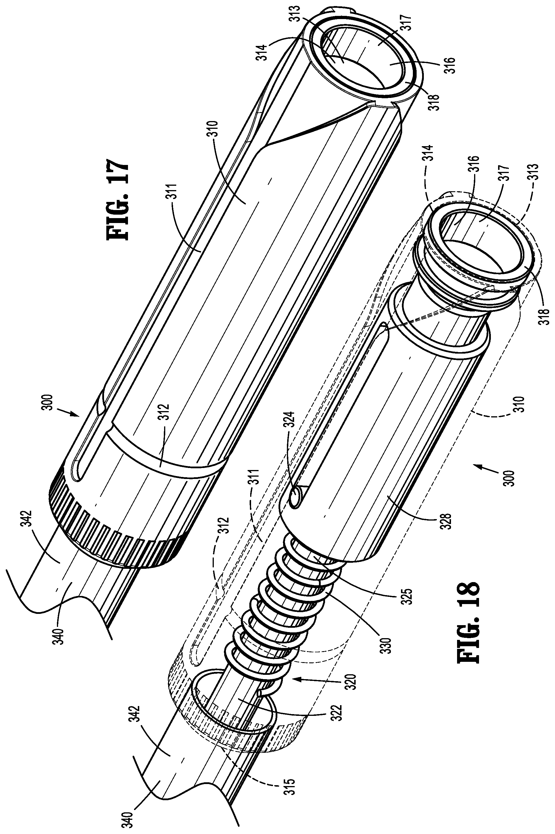
D00013
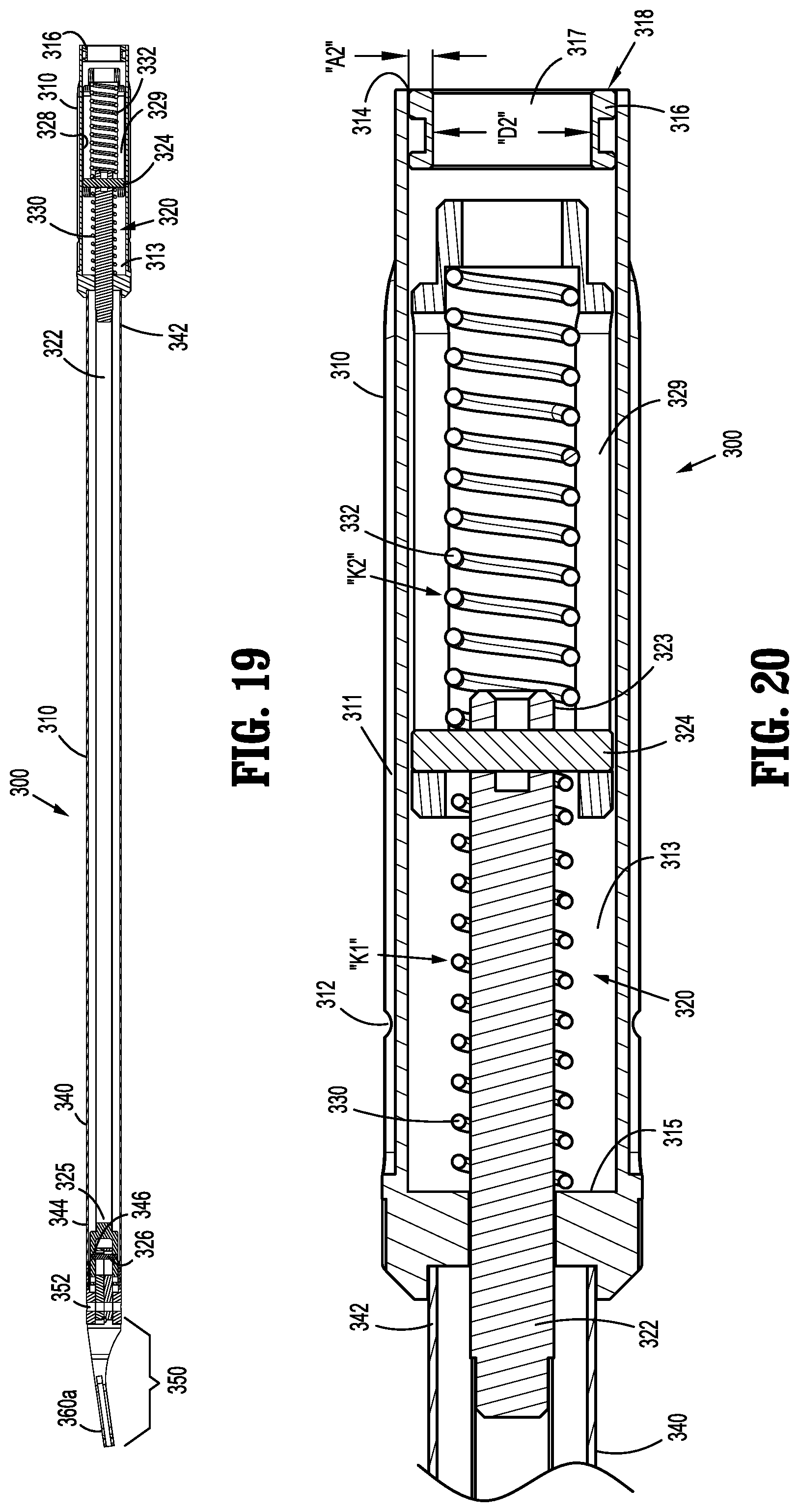
D00014
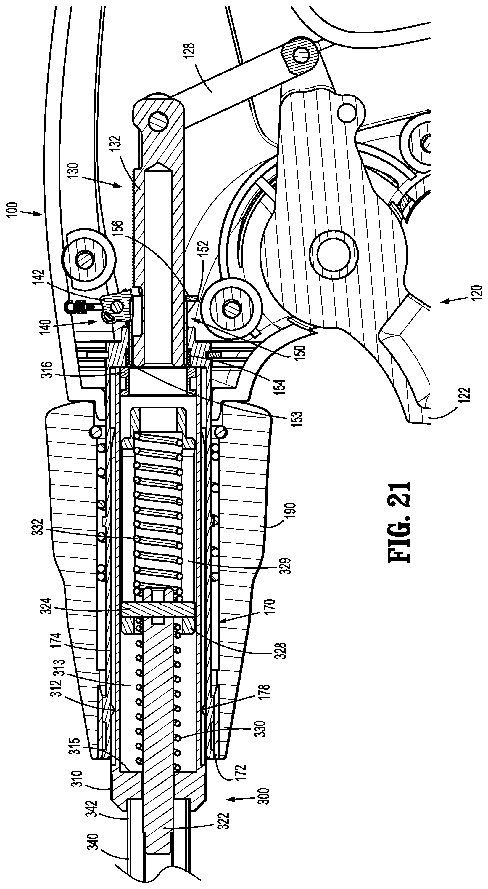
D00015

D00016
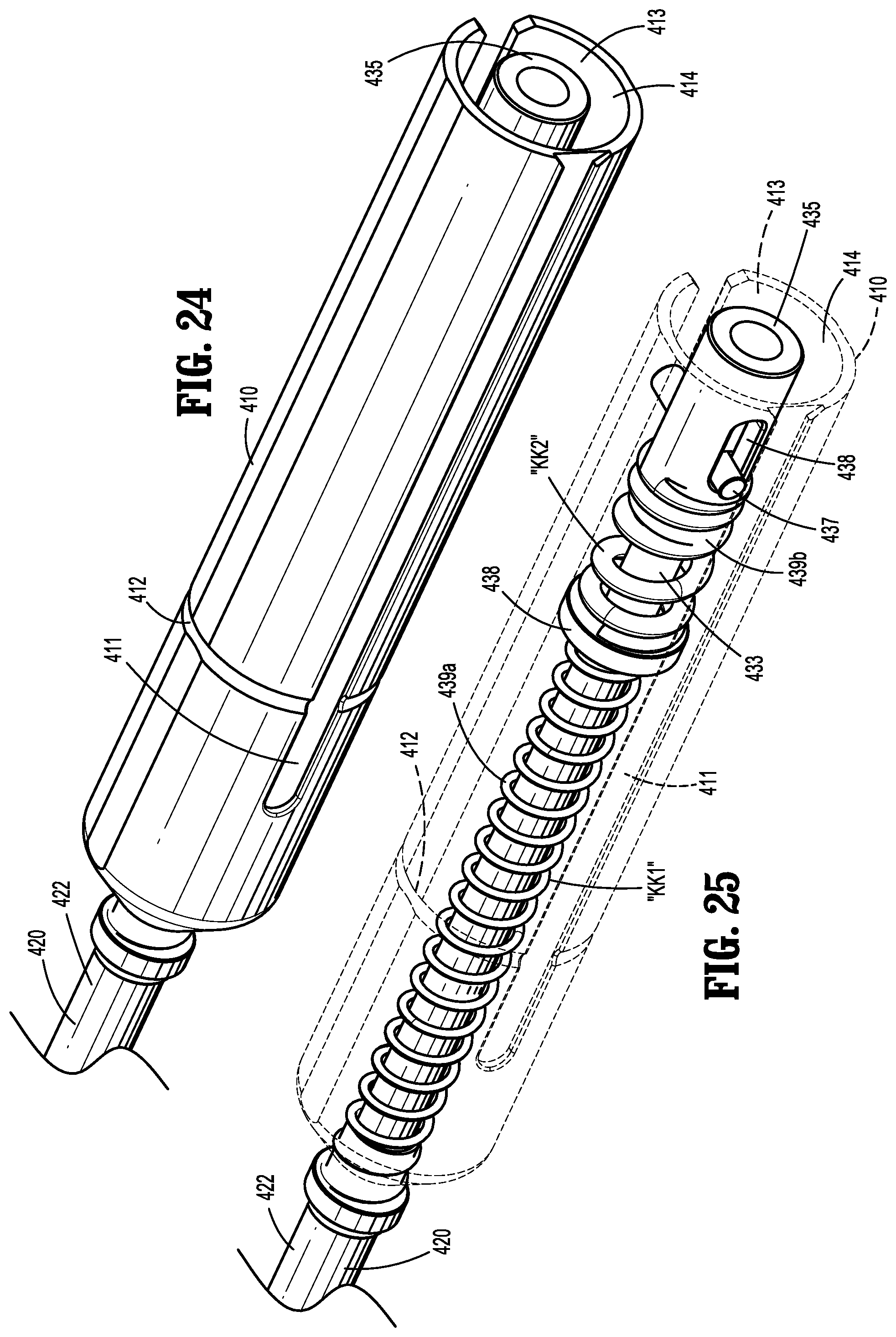
D00017
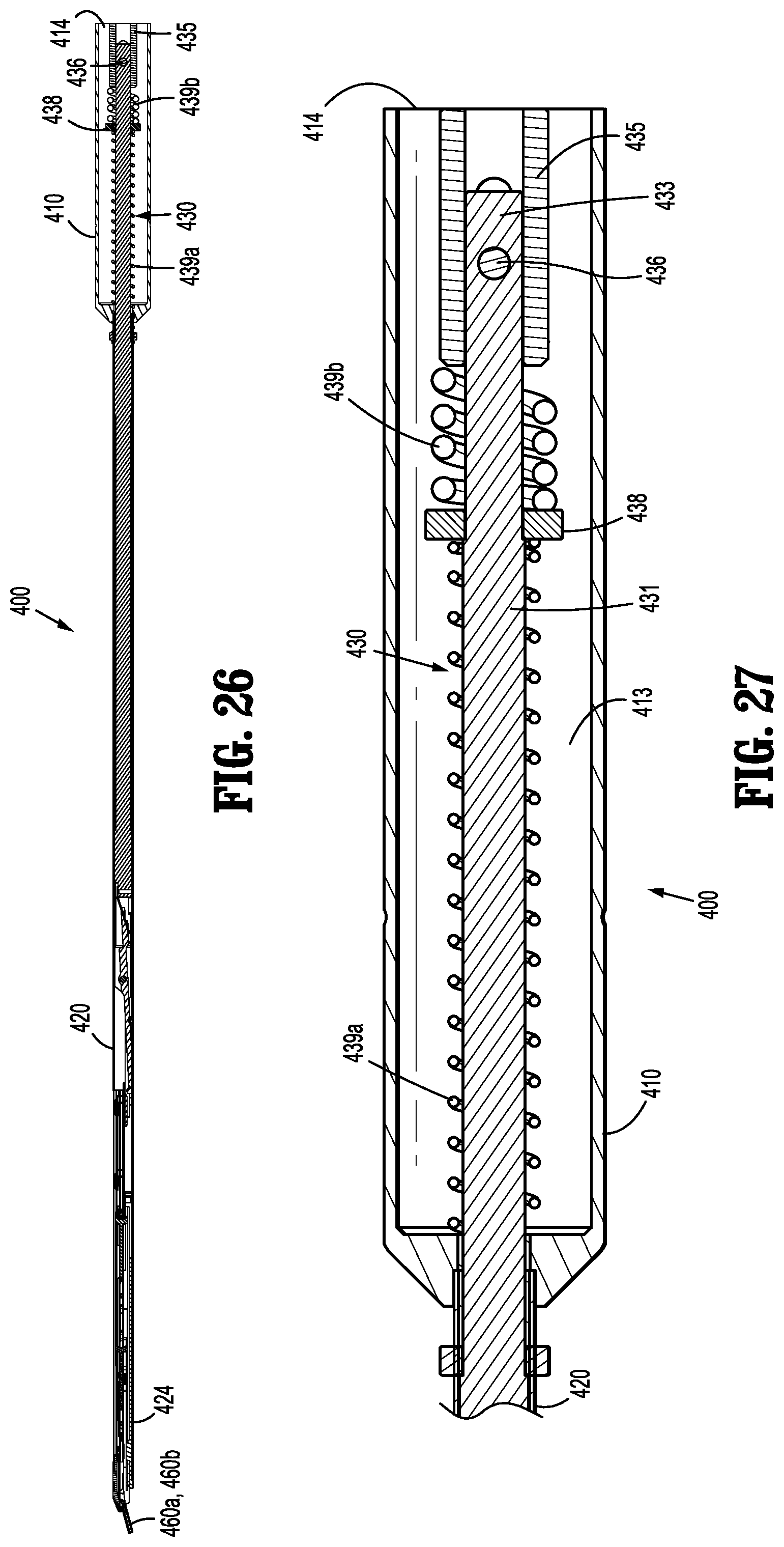
D00018

D00019
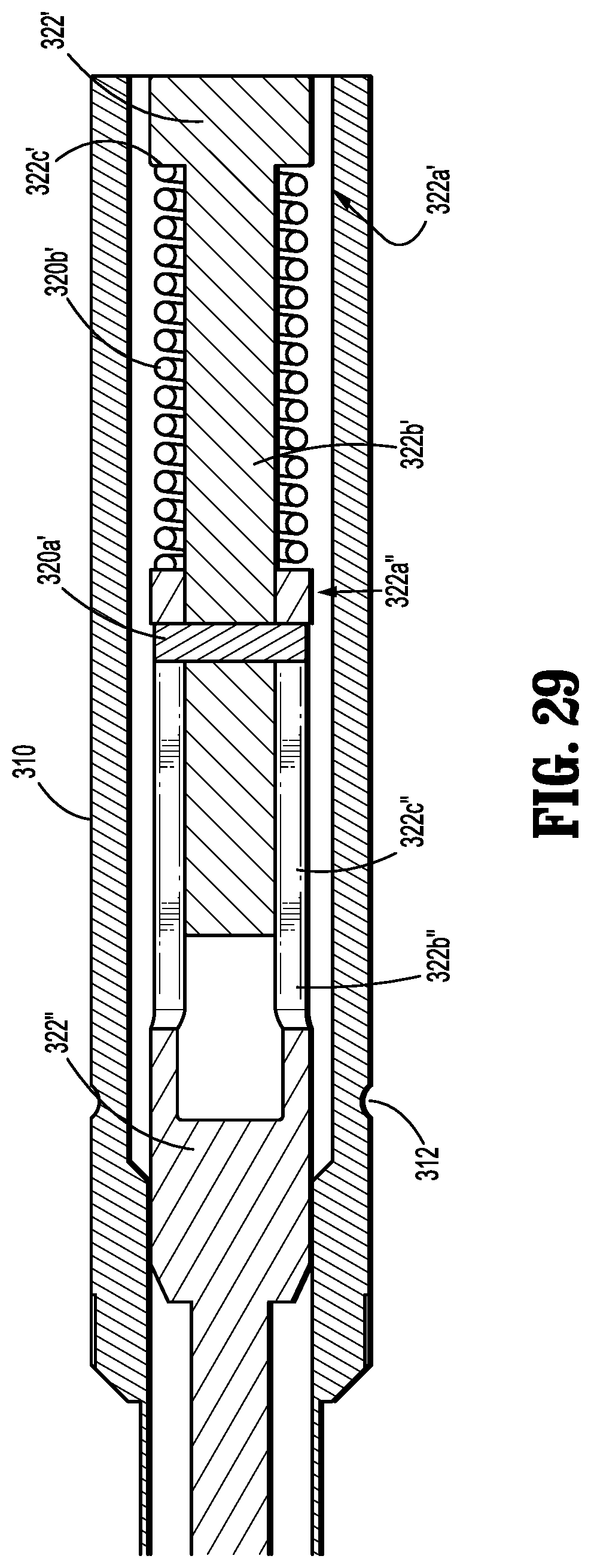
D00020

D00021
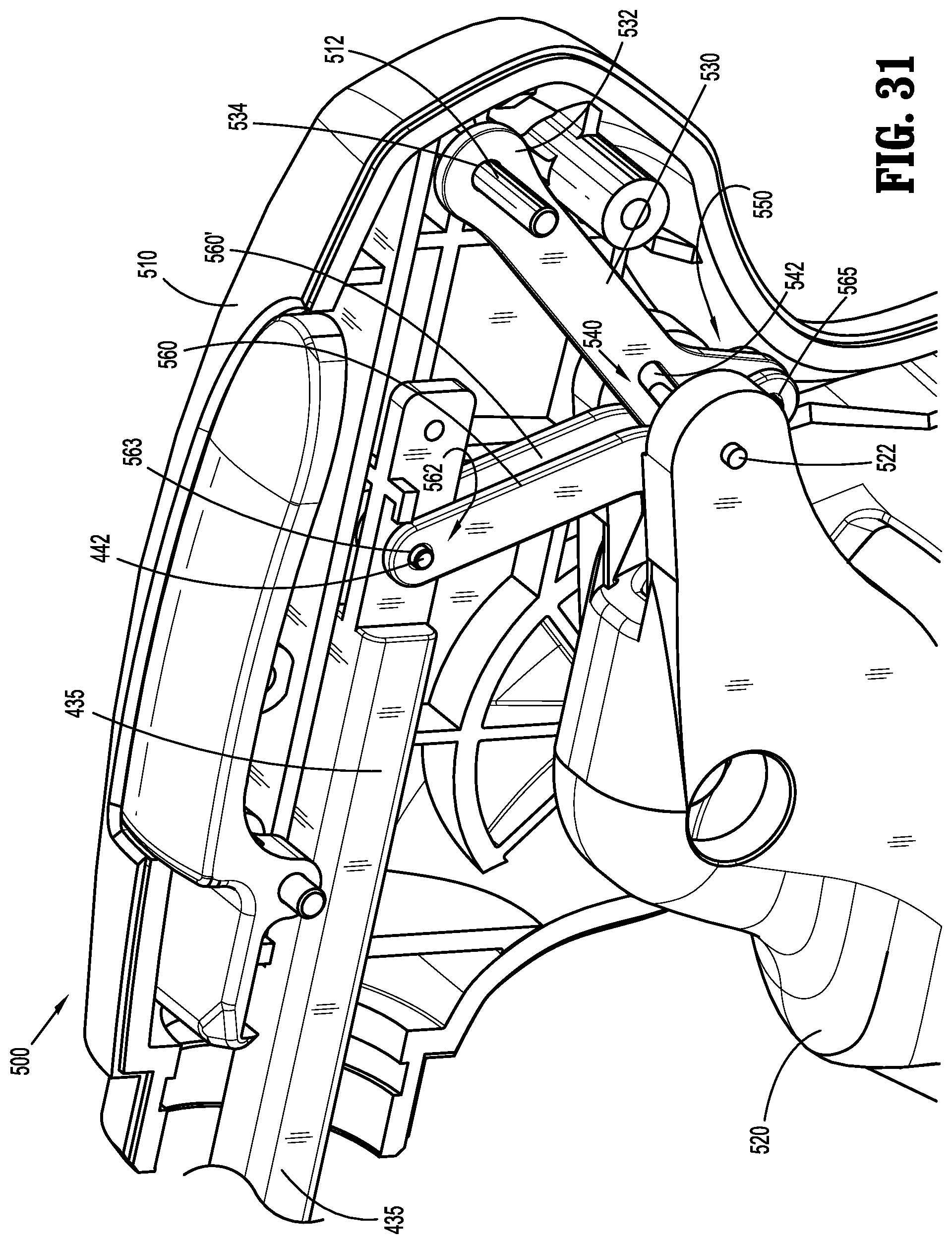
D00022
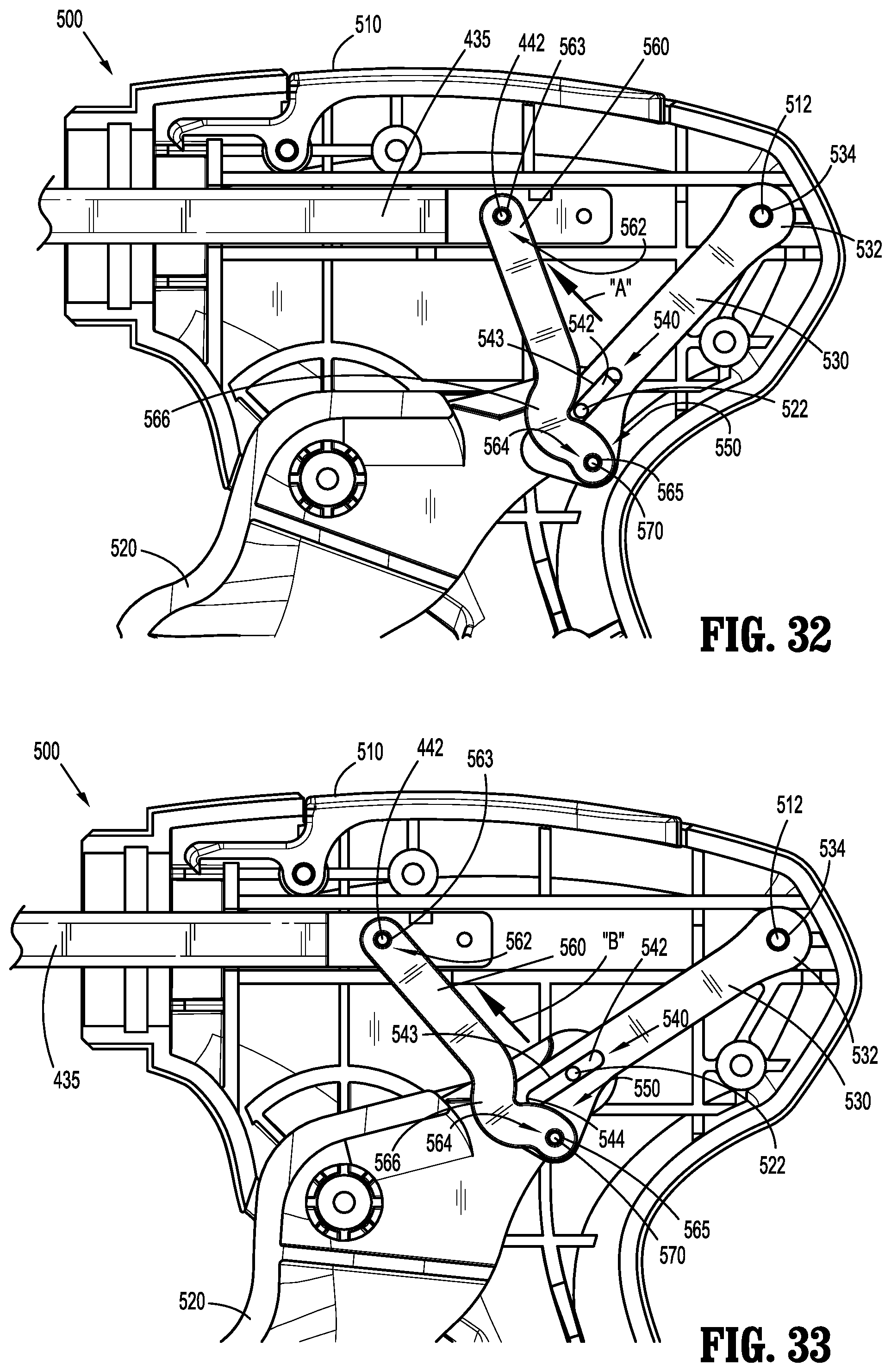
D00023
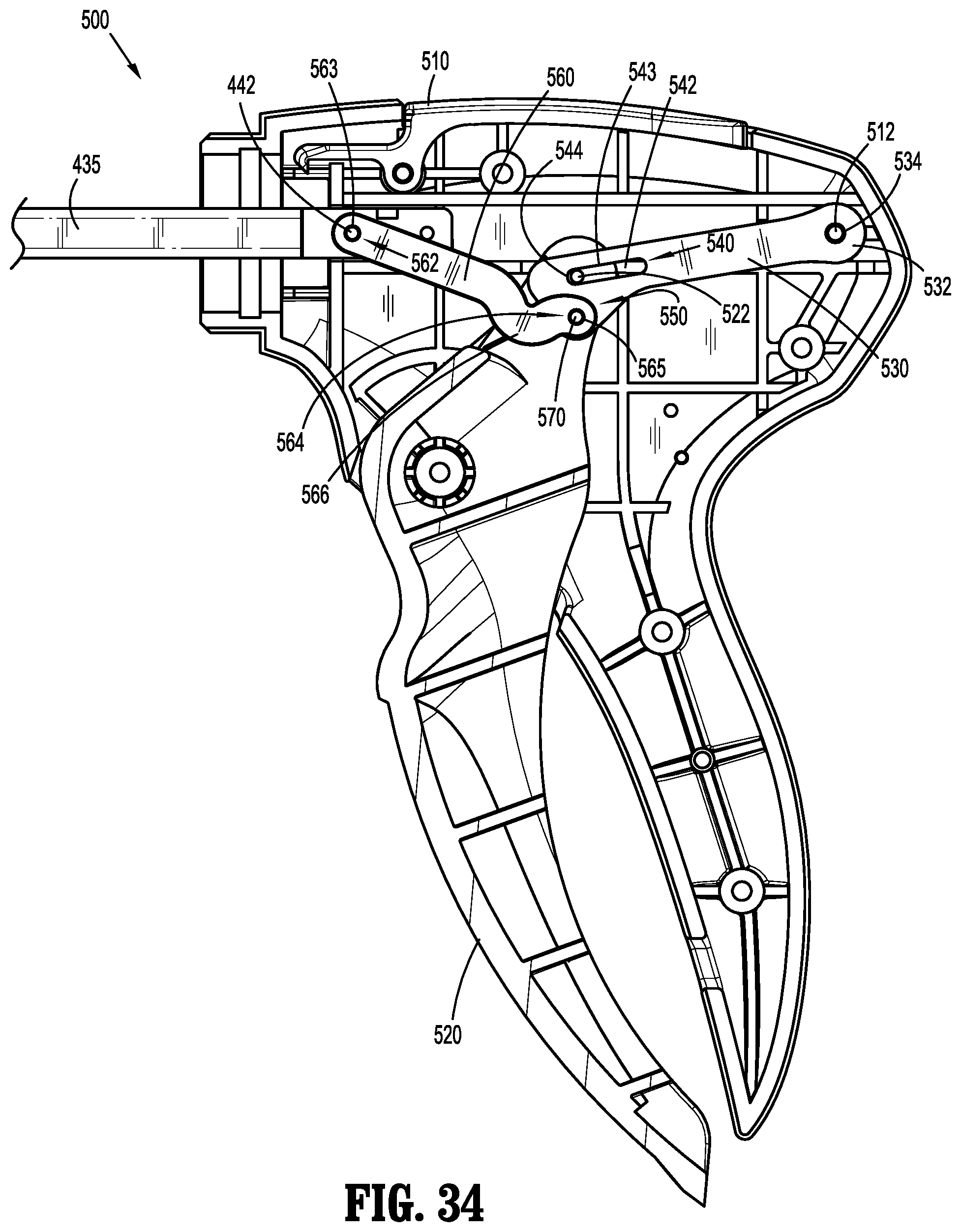
D00024
D00025

XML
uspto.report is an independent third-party trademark research tool that is not affiliated, endorsed, or sponsored by the United States Patent and Trademark Office (USPTO) or any other governmental organization. The information provided by uspto.report is based on publicly available data at the time of writing and is intended for informational purposes only.
While we strive to provide accurate and up-to-date information, we do not guarantee the accuracy, completeness, reliability, or suitability of the information displayed on this site. The use of this site is at your own risk. Any reliance you place on such information is therefore strictly at your own risk.
All official trademark data, including owner information, should be verified by visiting the official USPTO website at www.uspto.gov. This site is not intended to replace professional legal advice and should not be used as a substitute for consulting with a legal professional who is knowledgeable about trademark law.