Endoscope electro-pneumatic adaptor
Terliuc , et al. November 17, 2
U.S. patent number 10,835,107 [Application Number 15/562,439] was granted by the patent office on 2020-11-17 for endoscope electro-pneumatic adaptor. This patent grant is currently assigned to SMART MEDICAL SYSTEMS LTD.. The grantee listed for this patent is SMART MEDICAL SYSTEMS LTD.. Invention is credited to Gilad Luria, Amnon Potash, Gad Terliuc.


View All Diagrams
| United States Patent | 10,835,107 |
| Terliuc , et al. | November 17, 2020 |
Endoscope electro-pneumatic adaptor
Abstract
An endoscope system including an endoscope including an endoscope electro-pneumatic connection assembly having a leak test port, an endoscope electro-optic subsystem which is connectable to the endoscope via the endoscope electro-pneumatic connection assembly in a manner which precludes access to the leak test port when the endoscope electro-optic subsystem and the endoscope are connected at the electro-pneumatic connection assembly and an electro-pneumatic adaptor, which is connectable to the endoscope at the electro-pneumatic connection assembly and includes an adaptor electro-pneumatic connection assembly, including a leak test port connector for connection to the leak test port of the endoscope, an adaptor electrical port assembly to which the endoscope electro-optic subsystem is connectable and a pneumatic port.
| Inventors: | Terliuc; Gad (Ra'anana, IL), Luria; Gilad (Givatayim, IL), Potash; Amnon (Kibbutz Shefayim, IL) | ||||||||||
|---|---|---|---|---|---|---|---|---|---|---|---|
| Applicant: |
|
||||||||||
| Assignee: | SMART MEDICAL SYSTEMS LTD.
(Raanana, IL) |
||||||||||
| Family ID: | 57005323 | ||||||||||
| Appl. No.: | 15/562,439 | ||||||||||
| Filed: | March 31, 2016 | ||||||||||
| PCT Filed: | March 31, 2016 | ||||||||||
| PCT No.: | PCT/IL2016/050345 | ||||||||||
| 371(c)(1),(2),(4) Date: | September 28, 2017 | ||||||||||
| PCT Pub. No.: | WO2016/157189 | ||||||||||
| PCT Pub. Date: | October 06, 2016 |
Prior Publication Data
| Document Identifier | Publication Date | |
|---|---|---|
| US 20180084973 A1 | Mar 29, 2018 | |
Related U.S. Patent Documents
| Application Number | Filing Date | Patent Number | Issue Date | ||
|---|---|---|---|---|---|
| 62178207 | Apr 3, 2015 | ||||
| Current U.S. Class: | 1/1 |
| Current CPC Class: | A61B 1/00082 (20130101); A61B 1/00057 (20130101); A61B 1/00126 (20130101); A61B 1/12 (20130101); A61B 1/00124 (20130101); A61B 1/00128 (20130101); A61B 90/70 (20160201); A61B 2090/701 (20160201); A61M 25/1018 (20130101) |
| Current International Class: | A61B 1/00 (20060101); A61B 1/12 (20060101); A61B 90/70 (20160101); A61M 25/10 (20130101) |
References Cited [Referenced By]
U.S. Patent Documents
| 3837347 | September 1974 | Tower |
| 3895637 | July 1975 | Choy |
| 4040413 | August 1977 | Ohshiro |
| 4148307 | April 1979 | Utsugi |
| 4176662 | December 1979 | Frazer |
| 4195637 | April 1980 | Gruntzig et al. |
| 4224929 | September 1980 | Furihata |
| 4261339 | April 1981 | Hanson et al. |
| 4453545 | June 1984 | Inoue |
| 4616652 | October 1986 | Simpson |
| 4676228 | June 1987 | Krasner et al. |
| 4681093 | July 1987 | Ono et al. |
| 4690131 | September 1987 | Lyddy et al. |
| 4721123 | January 1988 | Cosentino et al. |
| 4862874 | September 1989 | Kellner |
| 4917088 | April 1990 | Crittenden |
| 5135487 | August 1992 | Morrill et al. |
| 5259366 | November 1993 | Reydel et al. |
| 5310524 | May 1994 | Campbell et al. |
| 5338299 | August 1994 | Barlow |
| 5411016 | May 1995 | Kume et al. |
| 5454364 | October 1995 | Kruger |
| 5569220 | October 1996 | Webster, Jr. |
| 5593419 | January 1997 | Segar |
| 5599301 | February 1997 | Jacobs et al. |
| 5607441 | March 1997 | Sierocuk et al. |
| 5653240 | August 1997 | Zimmon |
| 5693014 | December 1997 | Abele |
| 5700242 | December 1997 | Mulder |
| 5707382 | January 1998 | Sierocuk et al. |
| 5707392 | January 1998 | Kortenbach |
| 5823940 | October 1998 | Newman |
| 5904701 | May 1999 | Daneshvar |
| 5984860 | November 1999 | Shan |
| 6007482 | December 1999 | Madni et al. |
| 6162171 | December 2000 | Ng et al. |
| 6261260 | July 2001 | Maki et al. |
| 6412334 | July 2002 | Kral et al. |
| 6461294 | October 2002 | Oneda et al. |
| 6585639 | July 2003 | Kotmel et al. |
| 6589208 | July 2003 | Ewers et al. |
| 6663589 | December 2003 | Halevy |
| 6695810 | February 2004 | Peacock |
| 6702735 | March 2004 | Kelly |
| 6764441 | July 2004 | Chiel |
| 6986736 | January 2006 | Williams et al. |
| 7081096 | July 2006 | Brister et al. |
| 7169140 | January 2007 | Kume |
| 7635346 | December 2009 | Cabiri et al. |
| 7695428 | April 2010 | Machida |
| 7699771 | April 2010 | Wendlandt |
| 7713191 | May 2010 | Sekiguchi et al. |
| 7837672 | November 2010 | Intoccia |
| 7887480 | February 2011 | Sekiguchi |
| 7918788 | April 2011 | Lin et al. |
| 7963911 | June 2011 | Terliuc |
| 8002698 | August 2011 | Motai |
| 8012084 | September 2011 | Machida |
| 8152715 | April 2012 | Root et al. |
| 8187221 | May 2012 | Bates |
| 8197463 | June 2012 | Intoccia |
| 8273013 | September 2012 | Niwa et al. |
| 8348889 | January 2013 | Salemi et al. |
| 8419678 | April 2013 | Cabiri et al. |
| 8480572 | July 2013 | Ishigami |
| 8545382 | October 2013 | Suzuki et al. |
| 8727970 | May 2014 | Terliuc et al. |
| 8939895 | January 2015 | Simchony |
| 9119532 | September 2015 | Terliuc et al. |
| 9511209 | January 2016 | Drasler |
| 9278202 | March 2016 | Ranade |
| 9427142 | August 2016 | Terliuc et al. |
| 9480390 | November 2016 | Farhadi |
| 9521945 | December 2016 | Farhadi |
| 9596979 | March 2017 | Terliuc et al. |
| 9604042 | March 2017 | Fox |
| 9661994 | May 2017 | Terliuc et al. |
| 9795280 | October 2017 | Ueda |
| 9808142 | November 2017 | Axon et al. |
| 2001/0032494 | October 2001 | Greszler |
| 2002/0147385 | October 2002 | Butler et al. |
| 2003/0074015 | April 2003 | Nakao |
| 2003/0236495 | December 2003 | Kennedy |
| 2004/0077926 | April 2004 | Moriyama |
| 2004/0102681 | May 2004 | Gross |
| 2004/0210116 | October 2004 | Nakao |
| 2004/0236366 | November 2004 | Kennedy et al. |
| 2005/0027253 | February 2005 | Castellano et al. |
| 2005/0124856 | June 2005 | Fujikura et al. |
| 2005/0125005 | June 2005 | Fujikura |
| 2005/0133453 | June 2005 | Woodruff et al. |
| 2005/0137457 | June 2005 | Machida |
| 2005/0159702 | July 2005 | Sekiguchi et al. |
| 2005/0165233 | July 2005 | Hamedi et al. |
| 2005/0165273 | July 2005 | Takano |
| 2005/0171400 | August 2005 | Itoi |
| 2006/0095063 | May 2006 | Sekiguchi |
| 2006/0100480 | May 2006 | Ewers et al. |
| 2006/0111610 | May 2006 | Machida |
| 2006/0116549 | June 2006 | Sekiguchi et al. |
| 2006/0161044 | July 2006 | Oneda et al. |
| 2006/0282088 | December 2006 | Ryan |
| 2007/0010785 | January 2007 | Sekiguchi et al. |
| 2007/0038026 | February 2007 | Yoshida et al. |
| 2007/0083158 | April 2007 | Hirszowicz et al. |
| 2007/0185385 | August 2007 | Noguchi et al. |
| 2007/0191678 | August 2007 | Sekiguchi |
| 2007/0213586 | September 2007 | Hirose et al. |
| 2007/0244361 | October 2007 | Ikeda et al. |
| 2007/0270645 | November 2007 | Ikeda |
| 2007/0276181 | November 2007 | Terliuc |
| 2008/0009673 | January 2008 | Khachi |
| 2008/0161645 | July 2008 | Goldwasser et al. |
| 2008/0177142 | July 2008 | Roskopf |
| 2008/0200759 | August 2008 | Niwa et al. |
| 2008/0306441 | December 2008 | Brown et al. |
| 2009/0012469 | January 2009 | Nita |
| 2009/0018500 | January 2009 | Carter et al. |
| 2009/0048483 | February 2009 | Yamamoto |
| 2009/0156896 | June 2009 | Kura |
| 2009/0187069 | July 2009 | Terliuc et al. |
| 2009/0234188 | September 2009 | Matsuura et al. |
| 2009/0287058 | November 2009 | Terliuc |
| 2010/0041951 | February 2010 | Glozman et al. |
| 2010/0042046 | February 2010 | Chang et al. |
| 2010/0217185 | August 2010 | Terliuc et al. |
| 2012/0178994 | July 2012 | Schembre |
| 2012/0232342 | September 2012 | Reydel |
| 2012/0285488 | November 2012 | Labib et al. |
| 2013/0023920 | January 2013 | Terliuc et al. |
| 2013/0090527 | April 2013 | Axon |
| 2013/0116549 | May 2013 | Gunday |
| 2013/0197309 | August 2013 | Sakata |
| 2014/0088362 | March 2014 | Terliuc et al. |
| 2014/0155696 | June 2014 | Sakata |
| 2015/0073216 | March 2015 | Papay |
| 2015/0273191 | October 2015 | Terliuc et al. |
| 2015/0335229 | November 2015 | Terliuc |
| 2016/0022120 | January 2016 | Terliuc et al. |
| 2016/0081536 | March 2016 | Farhadi |
| 2016/0089001 | March 2016 | Hara et al. |
| 2016/0095508 | April 2016 | Terliuc et al. |
| 2017/0014099 | January 2017 | Morimoto |
| 2017/0027415 | February 2017 | Terliuc et al. |
| 2017/0027433 | February 2017 | Terliuc |
| 2017/0065155 | March 2017 | Farhadi |
| 2017/0216568 | March 2017 | Terliuc et al. |
| 2017/0100017 | April 2017 | Terliuc et al. |
| 2017/0106173 | April 2017 | Chanduszko |
| 2017/0181606 | June 2017 | Waagen |
| 2017/0203080 | July 2017 | Terliuc et al. |
| 2017/0360282 | December 2017 | Terliuc et al. |
| 2018/0125606 | May 2018 | Labib |
| 2018/0140175 | May 2018 | Luria |
| 2018/0333043 | November 2018 | Terliuc et al. |
| 2661242 | Oct 2010 | CA | |||
| 1394543 | Feb 2003 | CN | |||
| 2624936 | Jul 2004 | CN | |||
| 1550203 | Dec 2004 | CN | |||
| 1636502 | Jul 2005 | CN | |||
| 1647747 | Aug 2005 | CN | |||
| 1649630 | Aug 2005 | CN | |||
| 1827031 | Sep 2006 | CN | |||
| 1917802 | Feb 2007 | CN | |||
| 1933766 | Mar 2007 | CN | |||
| 1946328 | Apr 2007 | CN | |||
| 1951312 | Apr 2007 | CN | |||
| 1964665 | May 2007 | CN | |||
| 101015440 | Aug 2007 | CN | |||
| 101103898 | Jan 2008 | CN | |||
| 101243965 | Aug 2008 | CN | |||
| 101347321 | Jan 2009 | CN | |||
| 101380220 | Mar 2009 | CN | |||
| 101396256 | Apr 2009 | CN | |||
| 101522091 | Sep 2009 | CN | |||
| 101541227 | Sep 2009 | CN | |||
| 101664560 | Mar 2010 | CN | |||
| 102791180 | Nov 2012 | CN | |||
| 103269638 | Aug 2013 | CN | |||
| 4317601 | Dec 1994 | DE | |||
| 10209993 | Apr 2003 | DE | |||
| 0 212 696 | Mar 1987 | EP | |||
| 0473045 | Mar 1992 | EP | |||
| 0733342 | Sep 1996 | EP | |||
| 1433410 | Jun 2004 | EP | |||
| 1547641 | Jun 2005 | EP | |||
| 1550465 | Jul 2005 | EP | |||
| 1656879 | May 2006 | EP | |||
| 1666864 | Jun 2006 | EP | |||
| 1707221 | Oct 2006 | EP | |||
| 1556118 | Dec 2006 | EP | |||
| 2108303 | Oct 2009 | EP | |||
| 1726248 | Dec 2010 | EP | |||
| 1335659 | Apr 2011 | EP | |||
| 1551316 | Aug 2011 | EP | |||
| 2110068 | Aug 2011 | EP | |||
| 2764818 | Aug 2014 | EP | |||
| 1706169 | May 2015 | EP | |||
| 2320984 | Oct 2015 | EP | |||
| S48-068542 | Jun 1973 | JP | |||
| SHO50-016762 | Feb 1975 | JP | |||
| JPS57-57804 | Apr 1982 | JP | |||
| S62-002925 | Jun 1985 | JP | |||
| SHO61-284226 | Dec 1986 | JP | |||
| SHO62-002925 | Jan 1987 | JP | |||
| S61-202274 | Jul 1988 | JP | |||
| SHO63-102429 | Jul 1988 | JP | |||
| SHO64-017203 | Jan 1989 | JP | |||
| H2-58402 | Apr 1990 | JP | |||
| H04-102436 | Apr 1992 | JP | |||
| H04-297219 | Oct 1992 | JP | |||
| HEI 05337081 | Dec 1993 | JP | |||
| H06-63045 | Mar 1994 | JP | |||
| HEI6-339455 | Dec 1994 | JP | |||
| HEI7-12101 | Feb 1995 | JP | |||
| HEI7-148105 | Jun 1995 | JP | |||
| H08228996 | Sep 1996 | JP | |||
| HEI10-127571 | May 1998 | JP | |||
| HEI 10-286223 | Oct 1998 | JP | |||
| HEI10-286309 | Oct 1998 | JP | |||
| HEI11-225947 | Aug 1999 | JP | |||
| 2000-060793 | Feb 2000 | JP | |||
| 2000-189385 | Jul 2000 | JP | |||
| 2000-329534 | Nov 2000 | JP | |||
| 2002-34900 | Feb 2002 | JP | |||
| 2002-301019 | Oct 2002 | JP | |||
| 2003-275173 | Sep 2003 | JP | |||
| 2003250896 | Sep 2003 | JP | |||
| 2004-97718 | Apr 2004 | JP | |||
| 2004-329720 | Nov 2004 | JP | |||
| 2005-185704 | Jul 2005 | JP | |||
| 2005-185706 | Jul 2005 | JP | |||
| 2005-185707 | Jul 2005 | JP | |||
| 2005-205181 | Aug 2005 | JP | |||
| 2005-279128 | Oct 2005 | JP | |||
| 2005296256 | Oct 2005 | JP | |||
| 2005-334475 | Dec 2005 | JP | |||
| 2006-130014 | May 2006 | JP | |||
| 2006-167310 | Jun 2006 | JP | |||
| 2006-304906 | Nov 2006 | JP | |||
| 2006-334149 | Dec 2006 | JP | |||
| 2007-014475 | Jan 2007 | JP | |||
| 2007-026814 | Feb 2007 | JP | |||
| 2007-130082 | May 2007 | JP | |||
| 2007-517576 | Jul 2007 | JP | |||
| 2007-521907 | Aug 2007 | JP | |||
| 2007-268137 | Oct 2007 | JP | |||
| 2007-268147 | Oct 2007 | JP | |||
| 2007-296054 | Nov 2007 | JP | |||
| 2008-006000 | Jan 2008 | JP | |||
| 2008125886 | Jun 2008 | JP | |||
| 2008-537493 | Sep 2008 | JP | |||
| 2009-056121 | Mar 2009 | JP | |||
| 2009-195321 | Sep 2009 | JP | |||
| 2009-537212 | Oct 2009 | JP | |||
| 2009-254554 | Nov 2009 | JP | |||
| 2012504431 | Apr 2010 | JP | |||
| 96/00099 | Jan 1996 | WO | |||
| 98/30249 | Jul 1998 | WO | |||
| 02/094087 | Nov 2002 | WO | |||
| 2005/017854 | Feb 2005 | WO | |||
| 2005/074377 | Aug 2005 | WO | |||
| 2005/089625 | Sep 2005 | WO | |||
| WO2006123590 | Nov 2006 | WO | |||
| 2007/023492 | Mar 2007 | WO | |||
| 2007/135665 | Nov 2007 | WO | |||
| 2008/004228 | Jan 2008 | WO | |||
| WO2008073126 | Jun 2008 | WO | |||
| WO2008121143 | Oct 2008 | WO | |||
| 2008/142685 | Nov 2008 | WO | |||
| 2009/122395 | Oct 2009 | WO | |||
| 2010/046891 | Apr 2010 | WO | |||
| WO2010070291 | Jun 2010 | WO | |||
| 2010/137025 | Dec 2010 | WO | |||
| 2011/111040 | Sep 2011 | WO | |||
| 2014/188402 | Nov 2014 | WO | |||
| WO2014188402 | Nov 2014 | WO | |||
| WO2015160970 | Oct 2015 | WO | |||
| WO2016103247 | Jun 2016 | WO | |||
| WO2017004432 | Jan 2017 | WO | |||
Other References
|
An International Search Report and a Written Opinion both dated Sep. 4, 2014, which issued during the prosecution of Applicant's PCT/IL2014/000025. cited by applicant . An International Preliminary Report on Patentability dated Nov. 24, 2015, which issued during the prosecution of Applicant's PCT/IL2014/000025. cited by applicant . European Search Report dated Jan. 4, 2017, which issued during the prosecution of Applicant's European App No. 14800390.8. cited by applicant . An Office Action dated Dec. 9, 2016, which issued during the prosecution of Chinese Patent Application No. 201480029252.5. cited by applicant . European Search Report dated Apr. 8, 2014, which issued during the prosecution of Applicant's European App No. 11752941.2. cited by applicant . An Office Action dated May 25, 2016, which issued during the prosecution of Chinese Patent Application No. 201410483767.9. cited by applicant . An International Search Report and a Written Opinion both dated Oct. 18, 2011 which issued during the prosecution of Applicant's PCT/IL2011/000222. cited by applicant . An International Preliminary Report on Patentability dated Sep. 11, 2012, which issued during the prosecution of Applicant's PCT/IL2011/000222. cited by applicant . An Office Action dated Mar. 16, 2017, which issued during the prosecution of Chinese Patent Application No. 201410483767.9. cited by applicant . An Office Action dated Jun. 25, 2015, which issued during the prosecution of U.S. Appl. No. 13/583,634. cited by applicant . An Office Action dated Apr. 3, 2015, which issued during the prosecution of Japanese Patent Application No. 2012-556642. cited by applicant . An Office Action dated Sep. 16, 2016, which issued during the prosecution of Japanese Patent Application No. 2015-175589. cited by applicant . An Office Action dated Feb. 11, 2015, which issued during the prosecution of Chinese Patent Application No. 2011/0013002.9. cited by applicant . An Office Action dated Aug. 4, 2014, which issued during the prosecution of Chinese Patent Application No. 2011/0013002.9. cited by applicant . An Office Action dated Feb. 22, 2017, which issued during the prosecution of U.S. Appl. No. 13/583,634. cited by applicant . An Office Action dated Apr. 4, 2014, which issued during the prosecution of U.S. Appl. No. 13/583,634. cited by applicant . An Office Action dated Nov. 5, 2014, which issued during the prosecution of U.S. Appl. No. 13/583,634. cited by applicant . An Office Action dated Jun. 14, 2016, which issued during the prosecution of U.S. Appl. No. 13/583,634. cited by applicant . Notice of Allowance dated May 28, 2015, which issued during the prosecution of Chinese Patent Application No. 2011/0013002.9. cited by applicant . An Office Action dated May 24, 2016, which issued during the prosecution of Chinese Patent Application No. 201510483997.5. cited by applicant . An Office Action dated Jul. 20, 2016, which issued during the prosecution of Chinese Patent Application No. 201510483785.7. cited by applicant . An Office Action dated May 24, 2017, which issued during the prosecution of Chinese Patent Application No. 201510483785.7. cited by applicant . An Office Action dated Jun. 3, 2016, which issued during the prosecution of Chinese Patent Application No. 201410484557.1. cited by applicant . An Office Action dated Mar. 15, 2017, which issued during the prosecution of Chinese Patent Application No. 201410484557.1. cited by applicant . An Office Action dated Jun. 1, 2016, which issued during the prosecution of Chinese Patent Application No. 201510484559.0. cited by applicant . An Office Action dated Mar. 20, 2017, which issued during the prosecution of Chinese Patent Application No. 201510483997.5. cited by applicant . An Office Action dated Mar. 20, 2017, which issued during the prosecution of Chinese Patent Application No. 201510484559.0. cited by applicant . An Office Action dated Apr. 25, 2016, which issued during the prosecution of Chinese Patent Application No. 201510484558.6. cited by applicant . Notice of Allowance dated Mar. 10, 2017, which issued during the prosecution of Chinese Patent Application No. 201510484558.6. cited by applicant . An International Search Report and a Written Opinion both dated Jul. 13, 2012, which issued during the prosecution of Applicant's PCT/IL12/00003. cited by applicant . An International Preliminary Report on Patentability dated Sep. 10, 2013, which issued during the prosecution of Applicant's PCT/IL12/00003. cited by applicant . An Office Action dated Mar. 13, 2017, which issued during the prosecution of Chinese Patent Application No. 201510484566.0. cited by applicant . An Office Action dated Apr. 25, 2016, which issued during the prosecution of Chinese Patent Application No. 201510484566.0. cited by applicant . An Office Action dated Feb. 1, 2016, which issued during the prosecution of Australian Patent Application No. 2011225671. cited by applicant . Notice of Allowance dated Feb. 10, 2017, which issued during the prosecution of Australian Patent Application No. 2011225671. cited by applicant . Single Balloon Endoscope: Balloon pump control OBCU: http://medical.olympusamerica.com/products/control/ballooncontrol-unit-ob- cu,[online]. cited by applicant . Single Balloon Endoscope: SIF-Q 1 80 enteroscope: http://medical.olympusamerica.com/products/enteroscope/evisexera-ii-sif-q- 180,[online]. cited by applicant . An Office Action dated Jan. 21, 2016, which issued during the prosecution of Canadian Patent Application No. 2,791,838. cited by applicant . European Search Report dated Jul. 16, 2014, which issued during the prosecution of Applicant's European App No. 12754885.7. cited by applicant . EVIS EXERA II CLV-180 product brochure, http://www.olympus.nl/medical/en/medical_systems/hidden/downloadJsp.jsp?l- ink=/medical/rmt/media/content/content 1/documents 1/brochures 1/ EVIS_EXERA_11_CLV-180_product_brochure_001_V1-en_GB_20000101.pdf, [online]. cited by applicant . BS-2 Front Balloon, http://www.fujifilmusa.com/products/medical/endoscopy/endoscopes/speciali- zed-balloons-andovertube/index.html#balloonsspecifications, [online]. cited by applicant . An Office Action dated Jan. 30, 2017, which issued during the prosecution of Canadian Patent Application No. 2,791,838. cited by applicant . Double Balloon Endoscope: EC-450B15 colonoscope: http://www.fujifilmusa.com/products.medical/endoscopy/endoscopes/enterosc- opes/index.html,[online]. cited by applicant . Double Balloon Endoscope: Balloon pump controller BP-30: http://www.fujifilmusa.com/products/medical/endoscopy/endoscopes/balloon-- pump-controller/index.html,[online]. cited by applicant . Double Balloon Endoscope: EPX-4440HD video system: http://www.fujifilmusa.com/products/medical/endoscopy/video-systems/epx-4- 440hd, [online]. cited by applicant . Double Balloon Endoscope: TS-13 101 overtube: http://www.fujifilmusa.com/products/medical/endoscopy/endoscopes/speciali- zed-balloons-and-overtube/index.html,[online]. cited by applicant . Single Balloon Endoscope: ST-SB 1 overtube: http://medical.olympusamerica.com/products/tubes/single-use-st-sb 11, [online]. cited by applicant . U.S. Appl. No. 61/855,688, filed May 21, 2013. cited by applicant . U.S. Appl. No. 61/962,383, filed Nov. 6, 2013. cited by applicant . A communication from the European Patent Office dated Jul. 23, 2015, which issued during the prosecution of European Application No. 12754885.7. cited by applicant . An Office Action dated Nov. 22, 2016, which issued during the prosecution of U.S. Appl. No. 13/583,634. cited by applicant . An Office Action dated Mar. 18, 2015, which issued during the prosecution of U.S. Appl. No. 13/583,634. cited by applicant . An Office Action dated May 9, 2016, which issued during the prosecution of U.S. Appl. No. 13/583,634. cited by applicant . An Office Action dated Oct. 7, 2015, which issued during the prosecution of U.S. Appl. No. 13/583,634. cited by applicant . An Office Action dated Mar. 28, 2017, which issued during the prosecution of U.S. Appl. No. 13/583,634. cited by applicant . A communication from the European Patent Office dated Jul. 6, 2016, which issued during the prosecution of European Application No. 12754885.7. cited by applicant . A communication from the European Patent Office dated May 17, 2017, which issued during the prosecution of European Application No. 12754885.7. cited by applicant . An Office Action dated Apr. 15, 2016, which issued during the prosecution of Chinese Patent Application No. 201280022024.6. cited by applicant . An Office Action dated May 26, 2015, which issued during the prosecution of Chinese Patent Application No. 201280022024.6. cited by applicant . An Office Action dated Nov. 1, 2016, which issued during the prosecution of Chinese Patent Application No. 201280022024.6. cited by applicant . An Office Action dated Dec. 9, 2016, which issued during the prosecution of Australian Patent Application No. 2012226390. cited by applicant . Notice of Allowance dated Dec. 22, 2016, which issued during the prosecution of Australian Patent Application No. 2012226390. cited by applicant . An Office Action dated Oct. 27, 2015, which issued during the prosecution of Japanese Patent Application No. 2013-557219. cited by applicant . An Office Action dated Oct. 24, 2016, which issued during the prosecution of Japanese Patent Application No. 2013-557219. cited by applicant . An Office Action dated Dec. 28, 2015, which issued during the prosecution of Japanese Patent Application No. 2015-004799. cited by applicant . An Office Action dated Dec. 6, 2016, which issued during the prosecution of Japanese Patent Application No. 2015-004799. cited by applicant . An Office Action dated Dec. 15, 2015, which issued during the prosecution of Australian Patent Application No. 2012226390. cited by applicant . An Office Action dated Sep. 3, 2015, which issued during the prosecution of Israel Patent Application No. 221621. cited by applicant . An Office Action dated Nov. 14, 2016, which issued during the prosecution of Israel Patent Application No. 228174. cited by applicant . An Office Action dated Jul. 5, 2017, which issued during the prosecution of Chinese Patent Application No. 201280022024.6. cited by applicant . An Office Action dated Jul. 18, 2017, which issued during the prosecution of Canadian Patent Application No. 2,828,608. cited by applicant . An Office Action dated Jul. 24, 2017, which issued during the prosecution of Japanese Patent Application No. 2012-556642. cited by applicant . A Notice of Allowance dated Aug. 24, 2017, which issued during the prosecution of Chinese Patent Application No. 201510484557.1. cited by applicant . An Office Action dated Sep. 18, 2017, which issued during the prosecution of U.S. Appl. No. 14/891,683. cited by applicant . Notice of Allowance in Chinese Patent App. No. 201510483785.7, dated Sep. 26, 2017. cited by applicant . Office Action in Chinese Patent App. No. 201510484566.0, dated Oct. 20, 2017. cited by applicant . Notice of Allowance in Chinese Patent App. No. 201510484557.1, dated Aug. 24, 2017. cited by applicant . Office Action in Chinese Patent App. No. 201510483767.9, dated Nov. 27, 2017. cited by applicant . Office Action in Chinese Patent App. No. 201510484559.0, dated Dec. 14, 2017. cited by applicant . Decision of Rejection in Chinese Patent App. No. 201510483997.5, dated Sep. 28, 2017. cited by applicant . Office Action in Chinese Patent App. No. 201480029252.5, dated Nov. 1, 2017. cited by applicant . Office Action in Australian Patent App. No. 2014269901, dated Jan. 12, 2018. cited by applicant . Office Action in Australian Patent App. No. 2017202285, dated Jan. 4, 2018. cited by applicant . Office Action in Canadian Patent App. No. 2,791,838, dated Dec. 15, 2017. cited by applicant . Final Rejection in U.S. Appl. No. 14/003,799, dated Oct. 5, 2017. cited by applicant . Non Final Rejection in U.S. Appl. No. 14/891,683, dated Sep. 18, 2017. cited by applicant . Office Action in JP 2016189043 dated Jul. 24, 2017. cited by applicant . Office Action in EP 11752941.2 dated Feb. 6, 2018. cited by applicant . Office Action in U.S. Appl. No. 14/003,799 dated Oct. 5, 2017. cited by applicant . Office Action in U.S. Appl. No. 14/003,799 dated Mar. 27, 2018. cited by applicant . Office Action in JP 2017012628 dated Feb. 26, 2018. cited by applicant . Office Action in JP 2016514529 dated Feb. 9, 2018. cited by applicant . International Preliminary Report on Patentability in WO/2016/157189 dated Oct. 3, 2017. cited by applicant . International Search Report in WO/2016/157189 dated Sep. 7, 2016. cited by applicant . Written Opinion of the International Search Authority in WO/2016/157189 dated Sep. 7, 2016. cited by applicant . International Search Report in WO/2016/103247 dated Mar. 17, 2016. cited by applicant . Written Opinion of the International Search Authority in WO/2016/103247 dated Mar. 17, 2016. cited by applicant . International Preliminary Report on Patentability in WO/2016/103247 dated Jun. 27, 2017. cited by applicant. |
Primary Examiner: Henderson; Ryan N
Attorney, Agent or Firm: AlphaPatent Associates, Ltd Swirsky; Daniel J.
Parent Case Text
CROSS-REFERENCE TO RELATED APPLICATIONS
This application is a U.S. National Phase Application under 35 U.S.C. 371 of International Application No. PCT/IL2016/050345, which has an international filing date of Mar. 31, 2016, and which claims the priority benefit of U.S. Provisional Patent Application Ser. No. 62/178,207, filed Apr. 3, 2015, and entitled ADAPTOR FOR USE WITH AN ENDOSCOPE, the description of which is hereby incorporated by reference.
Reference is also made to applicant's Published PCT Patent Applications WO2011/111040; WO/2012/120492; WO/2014/068569 and WO2014/188402, the disclosures of which are hereby incorporated by reference.
Claims
The invention claimed is:
1. An endoscope system comprising: an endoscope including an endoscope electro-pneumatic connection assembly having a leak test port; an endoscope electro-optic subsystem which is connectable to said endoscope via said endoscope electro-pneumatic connection assembly in a manner which precludes access to said leak test port when said endoscope electro-optic subsystem and said endoscope are directly connected at said electro-pneumatic connection assembly; and an electro-pneumatic adaptor being connectable to said endoscope at said electro-pneumatic connection assembly and comprising: a plurality of adaptor connectors, including an electrical connector for connection to an electrical connector of said endoscope, a pneumatic connector portion for connection to a pneumatic connector portion of said endoscope electro-pneumatic connection assembly, and a leak test port connector for connection to said leak test port of said endoscope, an adaptor electrical port connector to which said endoscope electro-optic subsystem is connectable, and a pneumatic connector assembly with a pneumatic conduit pneumatically connecting said pneumatic connector assembly to said leak test port connector.
2. An endoscope system according to claim 1 and wherein said leak test port communicates with an interior volume of said endoscope.
3. An endoscope system according to claim 1 and wherein: said endoscope is a balloon endoscope; and said pneumatic connector assembly of said electro-pneumatic adaptor is connected to a balloon inflation/deflation subsystem.
4. An endoscope system according to claim 3 and wherein said balloon inflation/deflation subsystem is adapted to provide inflation and deflation of said balloon via said pneumatic connector assembly of said adaptor, said leak test port and an interior volume of said endoscope.
5. An endoscope system according to claim 1 and wherein said electro-pneumatic adaptor is constructed such that said plurality of adaptor connectors, said adaptor electrical port assembly and said pneumatic connector assembly are directed at mutually different angles.
6. An endoscope system according to claim 1 and wherein said pneumatic connector assembly is fixedly connected to at least one of a leak tester and a balloon inflation/deflation subsystem.
7. An endoscope system according to claim 1 and wherein said pneumatic connector assembly of said electro-pneumatic adaptor is connected to a leak tester.
8. An endoscope system according to claim 3 and wherein said pneumatic connector assembly is removably connected to said balloon inflation/deflation subsystem.
Description
FIELD OF THE INVENTION
The present invention relates to endoscope systems generally and more particularly to adaptors useful in endoscope systems.
BACKGROUND OF THE INVENTION
Various types of endoscope systems are known.
SUMMARY OF THE INVENTION
The present invention seeks to provide an improved endoscope system.
There is thus provided in accordance with a preferred embodiment of the present invention an endoscope system including an endoscope including an endoscope electro-pneumatic connection assembly having a leak test port, an endoscope electro-optic subsystem which is connectable to the endoscope via the endoscope electro-pneumatic connection assembly in a manner which precludes access to the leak test port when the endoscope electro-optic subsystem and the endoscope are connected at the electro-pneumatic connection assembly and an electro-pneumatic adaptor, which is connectable to the endoscope at the electro-pneumatic connection assembly and includes an adaptor electro-pneumatic connection assembly, including a leak test port connector for connection to the leak test port of the endoscope, an adaptor electrical port assembly to which the endoscope electro-optic subsystem is connectable and a pneumatic port.
In accordance with a preferred embodiment of the present invention the pneumatic port includes a pneumatic connector assembly. Additionally or alternatively, the electro-pneumatic adaptor is removably connectable to the endoscope at the electro-pneumatic connection assembly. Alternatively or additionally, the leak test port communicates with an interior volume of the endoscope.
Preferably, the electro-pneumatic adaptor includes an electrical connector for connection to an electrical connector of the endoscope, a pneumatic connector portion for connection to the endoscope electro-pneumatic connection assembly and a leak test port connector for connection to the leak test port.
In accordance with a preferred embodiment of the present invention the endoscope is a balloon endoscope and the endoscope system also includes a balloon inflation/deflation subsystem which is connected to the pneumatic port. Additionally, the balloon inflation/deflation subsystem is adapted to provide inflation and deflation of the balloon via the pneumatic port of the adaptor, the leak test port and an interior volume of the endoscope.
In accordance with a preferred embodiment of the present invention the electro-pneumatic adaptor is constructed such that the adaptor electro-pneumatic connection assembly, the adaptor electrical port assembly and the pneumatic port are directed at mutually different angles.
Preferably, the electro-pneumatic adaptor includes a conduit pneumatically connecting the leak test port of the endoscope to the pneumatic port of the adaptor. Additionally or alternatively, the pneumatic port of the adaptor is fixedly connected to at least one of a leak tester and a balloon inflation/deflation subsystem.
In accordance with a preferred embodiment of the present invention the endoscope system also includes a leak tester which is connected to the pneumatic port.
Preferably, the balloon inflation/deflation subsystem is removably connected to the pneumatic port.
There is also provided in accordance with another preferred embodiment of the present invention an electro-pneumatic adaptor for use with an endoscope including an endoscope electro-pneumatic connection assembly having a leak test port, the electro-pneumatic adaptor being connectable to the endoscope at the electro-pneumatic connection assembly and including an adaptor electro-pneumatic connection assembly, including a leak test port connector for connection to the leak test port of the endoscope, an adaptor electrical port assembly and a pneumatic port.
In accordance with a preferred embodiment of the present invention the pneumatic port includes a pneumatic connector assembly. Additionally or alternatively, the electro-pneumatic adaptor is connectable to the endoscope at the electro-pneumatic connection assembly. Preferably, the leak test port communicates with an interior volume of the endoscope.
In accordance with a preferred embodiment of the present invention the adaptor electro-pneumatic connection assembly includes a pneumatic connector portion for connection to the endoscope electro-pneumatic connection assembly and a leak test port connector for connection to the leak test port.
Preferably, the endoscope is a balloon endoscope and the pneumatic port of the electro-pneumatic adaptor is connected to a balloon inflation/deflation subsystem. Additionally, the balloon inflation/deflation subsystem is adapted to provide inflation and deflation of the balloon via the pneumatic port of the adaptor, the leak test port and an interior volume of the endoscope.
In accordance with a preferred embodiment of the present invention the electro-pneumatic adaptor is constructed such that the adaptor electro-pneumatic connection assembly, the adaptor electrical port assembly and the pneumatic port are directed at mutually different angles.
Preferably, the electro-pneumatic adaptor also includes a conduit pneumatically connecting the leak test port of the endoscope to the pneumatic port of the adaptor.
In accordance with a preferred embodiment of the present invention the pneumatic port is fixedly connected to at least one of a leak tester and a balloon inflation/deflation subsystem.
Preferably, the pneumatic port of the electro-pneumatic adaptor is connected to a leak tester. In accordance with a preferred embodiment of the present invention the pneumatic port is removably connected to the balloon inflation/deflation subsystem.
There is further provided in accordance with yet another preferred embodiment of the present invention a method of employing an endoscope system which includes an endoscope including an endoscope electro-pneumatic connection assembly having a leak test port, an endoscope electro-optic subsystem which is connectable to the endoscope via the endoscope electro-pneumatic connection assembly in a manner which precludes access to the leak test port when the endoscope electro-optic subsystem and the endoscope are connected at the electro-pneumatic connection assembly and an electro-pneumatic adaptor, which is connectable to the endoscope at the electro-pneumatic connection assembly and includes an adaptor electro-pneumatic connection assembly, including a leak test port connector for connection to the leak test port of the endoscope, an adaptor electrical port assembly to which the endoscope electro-optic subsystem is connectable and a pneumatic port, the method including connecting the electro-pneumatic adaptor to the endoscope at the electro-pneumatic connection assembly and connecting the endoscope electro-optic subsystem to the adaptor port assembly of the electro-pneumatic adaptor and connecting at least one of a leak tester and a balloon inflation/deflation subsystem to the pneumatic port.
Preferably, at least one of the connecting steps includes removably connecting. Additionally or alternatively, the connecting at least one of the leak tester and the balloon inflation/deflation subsystem to the pneumatic port connects the at least one of the leak tester and the balloon inflation/deflation subsystem to an interior volume of the endoscope.
In accordance with a preferred embodiment of the present invention the method also includes connecting an electrical connector of the adaptor to an electrical connector of the endoscope, connecting a pneumatic connector portion of the adaptor to the endoscope electro-pneumatic connection assembly and connecting the leak test port connector for connection to the leak test port of the endoscope.
Preferably, the endoscope is a balloon endoscope and the method also includes removably connecting the balloon inflation/deflation subsystem to the pneumatic port. Additionally, the balloon inflation/deflation subsystem provides inflation and deflation of the balloon via the pneumatic port of the adaptor, the leak test port and an interior volume of the endoscope.
Preferably, the pneumatic port of the adaptor is fixedly connected to at least one of the leak tester and the balloon inflation/deflation subsystem.
BRIEF DESCRIPTION OF THE DRAWINGS
The present invention will be understood and appreciated more fully from the drawings in which:
FIG. 1 is a simplified illustration of an endoscope system constructed and operative in accordance with a preferred embodiment of the present invention;
FIGS. 2A and 2B are simplified illustrations of a balloon endoscope system constructed and operative in accordance with another preferred embodiment of the present invention showing respective connections to a leak testing subsystem and to a balloon inflation/deflation subsystem;
FIGS. 3A, 3B and 3C are respectively pictorial assembled, sectional assembled and exploded view illustrations of an electro-pneumatic adaptor forming part of the endoscope systems of FIGS. 1, 2A and 2B, FIG. 3B being a sectional illustration taken along lines IIIB-IIIB in FIG. 3A;
FIGS. 4A, 4B and 4C are simplified illustrations of a first pneumatic connector element, forming part of the electro-pneumatic adaptor of FIGS. 3A-3C, FIG. 4C being a sectional illustration taken along lines IVC-IVC in FIG. 4A;
FIGS. 5A, 5B, 5C and 5D are simplified illustrations of a main body portion of the electro-pneumatic adaptor of FIGS. 3A-3C, FIGS. 5A and 5B being pictorial illustrations taken along mutually opposite directions and FIGS. 5C & 5D being respective pictorial and plan view sectional illustrations taken along lines VC-VC in FIG. 5A;
FIG. 6 is a simplified illustration of an adaptor electrical connector assembly forming part of the electro-pneumatic adaptor of FIGS. 3A-3C;
FIGS. 7A, 7B and 7C are simplified illustrations of an electrical connector support block, forming part of the electro-pneumatic adaptor of FIGS. 3A-3C, FIG. 7C being a sectional illustration taken along lines VIIC-VIIC in FIG. 7A;
FIGS. 8A, 8B, 8C and 8D are simplified illustrations of a bayonet connection subassembly forming part of the electro-pneumatic adaptor of FIGS. 3A-3C, FIGS. 8A and 8B being pictorial illustrations taken along mutually opposite directions and
FIGS. 8C & 8D being sectional illustrations taken along respective lines VIIIC-VIIIC and VIIID-VIIID in FIG. 8A taken along mutually opposite directions;
FIGS. 9A, 9B, 9C and 9D are simplified illustrations of the electro-pneumatic adaptor of FIGS. 3A-3C without the main body portion and without the bayonet connection subassembly, FIGS. 9A and 9B being pictorial illustrations taken along mutually opposite directions and FIGS. 9C & 9D being respective pictorial and plan view sectional illustrations taken along lines IXC-IXC in FIG. 9A;
FIGS. 10A and 10B are simplified illustrations showing two operative orientations of the electro-pneumatic adaptor of FIGS. 3A-3C relative to an endoscope forming part of the balloon endoscope system of FIGS. 2A and 2B;
FIGS. 11A and 11B are simplified illustrations showing two operative orientations of the electro-pneumatic adaptor of FIGS. 3A-3C when connected to an electro-optic subsystem forming part of the balloon endoscope system of FIGS. 2A and 2B;
FIGS. 12A and 12B are simplified illustrations showing two operative orientations of the electro-pneumatic adaptor of FIGS. 3A-3C when connected to the leak testing subsystem forming part of the balloon endoscope system of FIG. 2A; and
FIGS. 13A and 13B are simplified illustrations showing two operative orientations of the electro-pneumatic adaptor of FIGS. 3A-3C relative to the inflation/deflation subsystem forming part of the balloon endoscope system of FIG. 2B.
DETAILED DESCRIPTION OF A PREFERRED EMBODIMENT
Reference is now made to FIG. 1, which is a simplified illustration of an endoscope system constructed and operative in accordance with a preferred embodiment of the present invention.
As seen in FIG. 1, there is provided an endoscope system 100 comprising an endoscope 102, which may be a suitable conventional endoscope, such as a CF-H180AL colonoscope, commercially available from Olympus Europe GmbH, of Wendenstra e 14-18, 20097, Hamburg, Germany. Endoscope 102 includes an endoscope electro-pneumatic connection assembly 104, including a leak test port 106 communicating with an interior volume 107 of endoscope 102, and includes a pneumatic connector portion 108 and an electrical connector 110 including a plurality of male pins 112.
In accordance with a preferred embodiment of the present invention there is provided an electro-pneumatic adaptor 120, which is removably connectable to endoscope 102 at the endoscope electro-pneumatic connection assembly 104 and includes an electrical connector 121, comprising a plurality of pins, for connection to electrical connector 110 of endoscope 102, a pneumatic connector portion 122 for connection to the pneumatic connector portion 108 of the endoscope electro-pneumatic connection assembly 104 and a leak test port connector 123 which engages the leak test port 106. The electro-pneumatic adaptor 120 also includes an adaptor electrical port connector 124 to which a connector 125 of an endoscope electro-optic subsystem 126 is connectable and a pneumatic connector assembly 128 for connection to a leak testing subsystem 130 via a leak testing subsystem connector 132. Leak testing subsystem connector 132 may be any suitable pneumatic connector, and preferably is similar to a conventional connector, forming part of conventional leak tester such as model SHA-P5, commercially available from Pentax Europe GmbH, of 104 Julius-Vosseler St., 22527 Hamburg, Germany.
In accordance with a preferred embodiment of the present invention the leak testing subsystem 130 communicates with the interior volume 107 of the endoscope 102 via leak test port 106.
Endoscope electro-optic subsystem 126 is a conventional endoscope electro-optical subsystem such as a CV-180 video processor, commercially available from Olympus Europe GmbH, of Wendenstra e 14-18, 20097, Hamburg, Germany.
It is appreciated that during conventional clinical use of endoscope 102 in performing an endoscopy examination, as known in the art, the endoscope 102 is connected directly to endoscope electro-optic subsystem 126, by connecting the connector 125 to endoscope electro-pneumatic connection assembly 104, thereby precluding access to leak test port 106 during the endoscopy procedure. It is further appreciated that preclusion of pneumatic access to leak test port 106 and thus to the interior volume 107 of endoscope 102, when said endoscope electro-optic subsystem 126 and said endoscope 102 are connected at said electro-pneumatic connection assembly 104, prevents leak testing of endoscope 102 during the endoscopy examination.
It is a particular feature of the present invention that electro-pneumatic adaptor 120 enables simultaneous electrical connection of endoscope 102 and endoscope electro-optic subsystem 126, and pneumatic communication between an external pneumatic device such as leak tester 130 and the leak test port 106 of endoscope 102, thereby enabling leak testing of endoscope 102 during an endoscopy examination.
Reference is now made to FIG. 2A, which is a simplified illustration of a balloon endoscope system constructed and operative in accordance with a preferred embodiment of the present invention.
As seen in FIG. 2A, there is provided a balloon endoscope system 200 comprising a balloon endoscope 202, which may be a suitable conventional balloon endoscope, such as a G-EYE.TM. H180AL colonoscope, commercially available from Smart Medical Systems, of 10 Hayetsira street, 4366356, Ra'anana, Israel. Aside from including a balloon 204, balloon endoscope 202 may be identical in all relevant respects to endoscope 102 (FIG. 1) and balloon endoscope system 200 may be identical in all relevant respects to endoscope system 100, identical elements being designated by identical reference numerals. Adaptor 120 is connected to a leak testing subsystem 130 via connector 132.
It is a particular feature of the present invention that electro-pneumatic adaptor 120 enables simultaneous electrical connection of balloon endoscope 202 and endoscope electro-optic subsystem 126, and pneumatic communication between an external pneumatic device such as leak tester 130 and the leak test port 106 of balloon endoscope 202, thereby enabling leak testing of balloon endoscope 202 during an endoscopy examination. Reference is now made to FIG. 2B, which is a simplified illustration of a balloon endoscope system 220, which is identical to the balloon endoscope system 200 of FIG. 2A but is connected to an inflation/deflation subsystem 230, via a connector 232, which may be identical to connector 132, instead of to a leak testing subsystem 130 as in the embodiment of FIG. 2A. In accordance with a preferred embodiment of the present invention the inflation/deflation subsystem communicates with the interior volume of the endoscope via leak test port 106 and provides inflation and deflation of the balloon 204 via the interior volume 107.
It is appreciated that had balloon endoscope 202 been connected directly to endoscope electro-optic subsystem 126 while performing an endoscopy examination, by connecting the connector 125 to endoscope electro-pneumatic connection assembly 104 as commonly known in the art, this would have precluded access to leak test port 106 and consequently would have precluded inflation and deflation of balloon 204 through interior volume 107 by inflation/deflation subsystem 230 during the endoscopy examination.
It is a particular feature of the present invention that electro-pneumatic adaptor 120 enables simultaneous electrical connection of balloon endoscope 202 and endoscope electro-optic subsystem 126, and pneumatic communication between an external pneumatic device such as inflation/deflation subsystem 230 and the interior of balloon endoscope 202, via the leak test port 106, thereby enabling inflation and deflation of balloon 204 of balloon endoscope 202 during an endoscopy examination.
Reference is now made to FIGS. 3A, 3B and 3C, which are respectively pictorial assembled, sectional assembled and exploded view illustrations of electro-pneumatic adaptor 120, forming part of the endoscope systems of FIGS. 1 and 2.
As seen in FIGS. 3A, 3B and 3C, the electro-pneumatic adaptor 120 comprises a main body portion 300, an adaptor electrical connector assembly 302, an electrical connector support block 304 and a bayonet connector assembly 306, for connection to endoscope electro-pneumatic connection assembly 104 (FIG. 1). Retaining shims 307, 308 and 309 are employed to retain adaptor electrical connector assembly 302 in main body portion 300.
A pneumatic conduit 310 extends through a channel 312 formed in electrical connector support block 304 and is coupled at one end 314 thereof to pneumatic connector assembly 128 (FIG. 1). It is seen clearly in FIGS. 3B and 3C that pneumatic connector assembly 128 includes first and second pneumatic connector elements 316 and 318.
First pneumatic connector element 316 is illustrated in FIGS. 4A-4C, to which reference is now made, and includes a generally circular cylindrical portion 320, having a longitudinal axis 322, which is integrally formed with a generally square flange portion 324, which extends in a plane generally perpendicular to longitudinal axis 322. An inner portion 326 extends inwardly from flange portion 324 and includes a bore 328 which extends along an axis 332, which intersects and is perpendicular to longitudinal axis 322.
Generally circular cylindrical portion 320 includes an outer bore portion 334, inwardly of which is defined an inner bore portion 336, both of which extend along longitudinal axis 322. Inner bore portion 336 terminates in a bore 338, which also extends along longitudinal axis 322 and intersects with and joins bore 328 at a 90 degree junction 340.
Second pneumatic connector element 318 may be a conventional pneumatic connector, such as EOG valve assembly model number D201-V2330-1, commercially available from Pentax Europe GmbH, of 104 Julius-Vosseler St., 22527 Hamburg, Germany.
Pneumatic conduit 310 is arranged to be coupled at an end 350 thereof, which constitutes leak test port connector 123 (FIG. 1) and is preferably equipped with an O-ring 352, to leak test port 106 (FIG. 1).
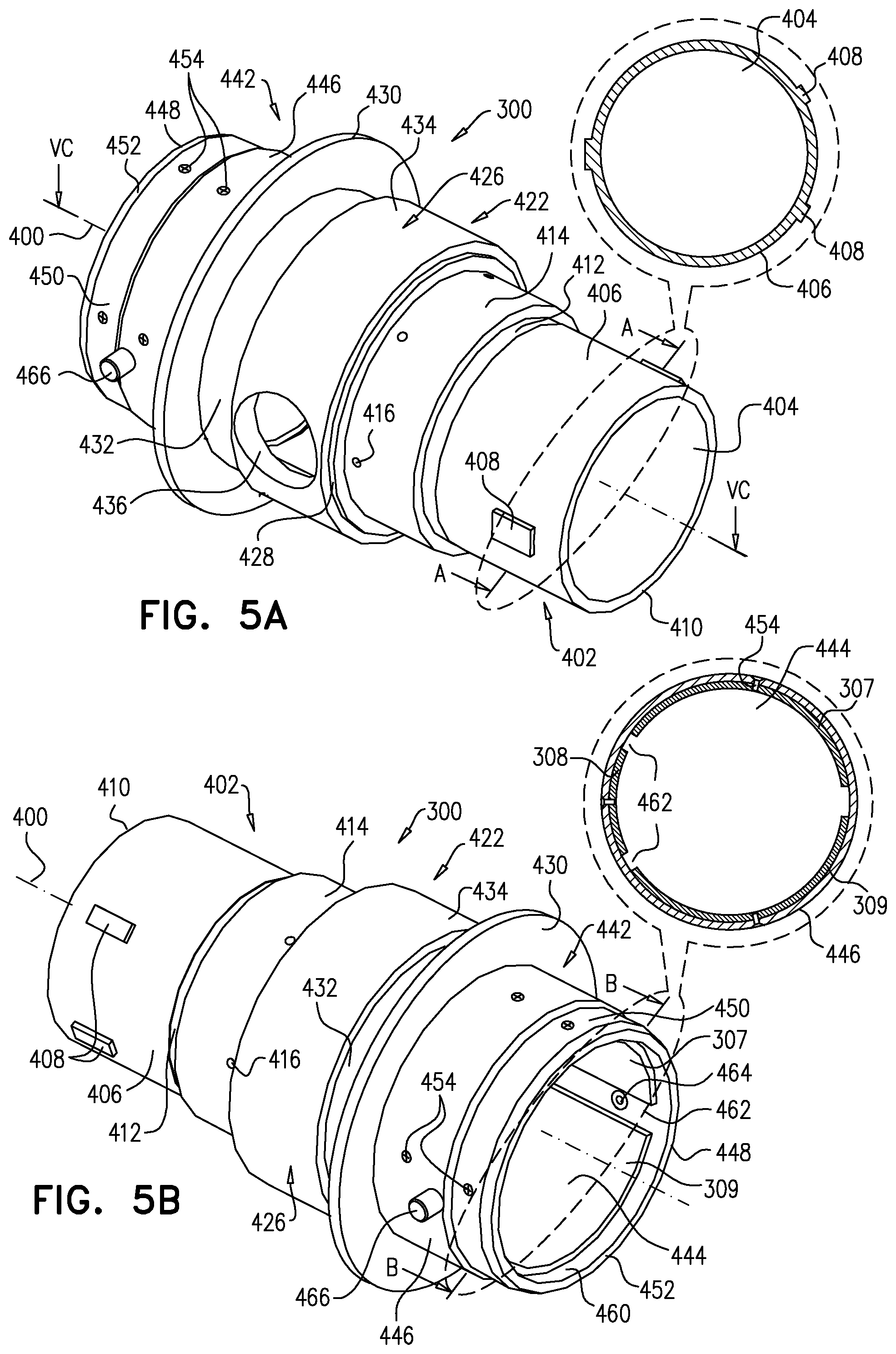
Main body portion 300 is illustrated in detail in FIGS. 5A-5D, to which reference is now made. As seen in FIGS. 5A-5D, main body portion 300 is a generally circularly symmetric integrally formed element arranged about a longitudinal axis 400 which includes a first generally circular cylindrical portion 402 having a generally circular cylindrical inner surface 404 and a generally circular cylindrical outer surface 406. Formed on generally circular cylindrical outer surface 406 are a plurality of mutually spaced generally rectangular radial protrusions 408, whose azimuthal distribution is shown in a sectional view portion of FIG. 5A.
Generally circular cylindrical outer surface 406 extends from an edge 410 to a shallow circumferential undercut 412. Adjacent undercut 412 is a circumferential protrusion 414 having formed therein a plurality of mutually spaced, radially extending apertures 416. Generally circular cylindrical inner surface 404 extends from edge 410 to a shoulder 418.
Axially adjacent first generally circular cylindrical portion 402 is a second generally circular cylindrical portion 422, having a generally circular cylindrical inner surface 424 and a generally circular cylindrical outer surface 426.
Generally circular cylindrical outer surface 426 extends from a shoulder 428 axially to a generally circular flange 430, axially adjacent to which is a relative undercut portion 432. Generally circular cylindrical outer surface 426 includes a circumferential protrusion 434 having formed therein a side aperture 436. Generally circular cylindrical inner surface 424 extends from shoulder 418 to a shoulder 438 and includes a side recess 440 surrounding side aperture 436.
Axially adjacent second generally circular cylindrical portion 422 is a third generally circular cylindrical portion 442, having a generally circular cylindrical inner surface 444 and a generally circular cylindrical outer surface 446.
Generally circular cylindrical outer surface 446 extends from flange 434 to an edge 448 and includes a forward undercut portion 450 and a chamfered portion 452 adjacent edge 448. Generally circular cylindrical inner surface 444 extends from shoulder 438 to edge 448. Disposed within and adjacent generally circular cylindrical inner surface 444 are mutually azimuthally spaced retaining shims 307, 308 and 309 (FIG. 3C), which are employed to retain adaptor electrical connector assembly 302 in main body portion 300. Shims 307, 308 and 309 are attached to main body portion, preferably by screws 454 which extend via apertures 456 formed in main body portion 300 and into correspondingly positioned threaded recesses 458 formed on outer surfaces of shims 307, 308 and 309.
Shims 307, 308 and 309 are attached to main body portion 300 only after insertion of adaptor electrical connector assembly 302 into main body portion 300 and are located so as to define therebetween a circumferential edge recess 460 and a plurality of axial recesses 462 which extend from circumferential edge recess 460 to shoulder 438.
A plurality of radially extending apertures 464 are formed in third generally circular cylindrical portion 442 and retain therein radially outwardly extending pins 466.
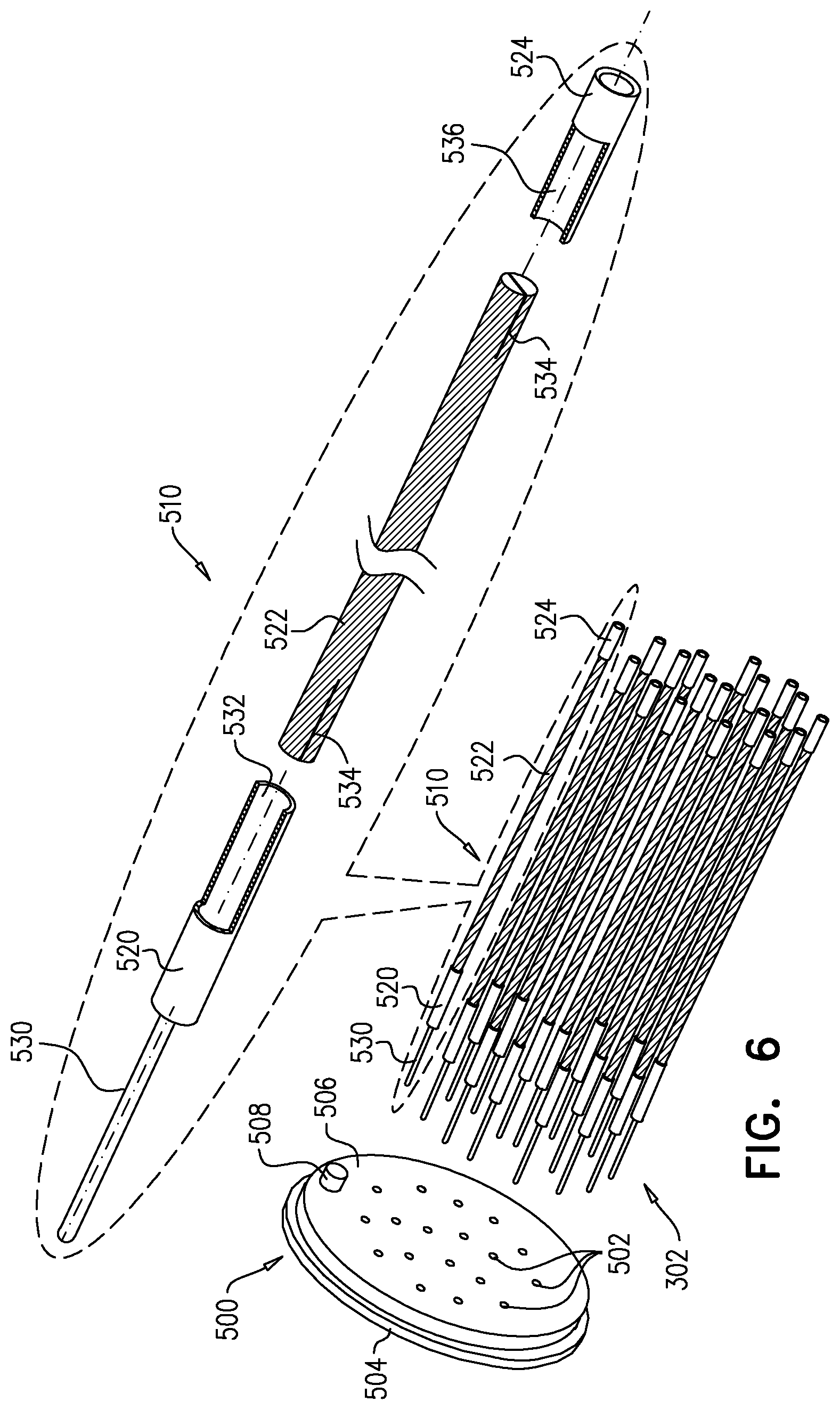
Adaptor electrical connector assembly 302 is illustrated in FIG. 6, to which reference is now made, and includes a base element 500 having a plurality of mutually spaced pin apertures 502 extending therethrough from a first generally planar surface 504 to a second planar surface 506. Second planar surface 506 is provided with an azimuthal orientation protrusion 508.
A plurality of electrical contact pin assemblies 510 are mounted onto base element 500, each at a pin mounting aperture 502, extending through base element 500. Each of electrical contact pin assemblies 510 preferably includes a male pin element 520 which is configured to be seated in and extend through base element 500, a generally circularly cylindrical intermediate pin shaft 522, and a female pin element 524.
Male pin element 520 is preferably an integrally formed element and includes an axial pin portion 530 and a socket 532 for retainably receiving a first end of intermediate pin shaft 522. Generally circularly cylindrical intermediate pin shaft 522 is preferably an elongate shaft, preferably having end slits 534 formed therein to provide resiliency. Female pin element 524 preferably is an integrally formed hollow cylindrical element, one end of which defines a socket 536 for retainably receiving a second end of intermediate pin shaft 522.
Electrical connector support block 304 is illustrated in FIGS. 7A-7C, to which reference is now made. As seen in FIGS. 7A-7C, electrical connector support block 304 is preferably an integrally formed, generally cylindrical element extending along an axis 550 and is preferably formed of a dielectric material such as DELRIN, ABS, or OKOLON.
Electrical connector support block 304 is preferably formed with a plurality of throughgoing generally circular cylindrical bores 552 which extend from a first end 554 of block 304 to a second end 556 of block 304. Bores 552 having a generally uniform cross-sectional radius along most of their extent 557 from first end 554 and have a short extent 558 adjacent second end 556 which has a lesser cross sectional radius. Each electrical contact pin assembly 510 is retained in an extent 557 of a bore 552. A recess 559 is formed at first end 554 of block 304 to accommodate azimuthal orientation protrusion 508 (FIG. 6).
As seen particularly in FIG. 7C, channel 312 terminates in a recess 560, which lies within an external recess 562, both of which accommodate an end of first pneumatic connector element 316.
Bayonet connector assembly 306 is illustrated in FIGS. 8A-8D, to which reference is now made. The overall construction and operation of bayonet connector assembly 306 is similar to that in Olympus MAJ-1430 Pigtail, commercially available from Olympus Europe GmbH, of Wendenstra e 14-18, 20097, Hamburg, Germany. Briefly stated, the bayonet connector assembly 306 includes a main cylindrical portion 570 having a pair of angled circumferential bayonet pin receiving slits 572 formed therein. A locking ring assembly 574, including a forward portion 576 and a rearward portion 578, cooperates with main cylindrical portion 570 in a conventional manner and is preferably spring loaded in a conventional manner. Details of the conventional bayonet connector assembly 306 are not shown or described in detail.
FIGS. 9A-9D illustrate the assembly of elements 302, 304, 310, 316 and 318 as described in detail hereinabove.
Reference is now made to FIGS. 10A and 10B, which are simplified illustrations showing two operative orientations of the electro-pneumatic adaptor of FIGS. 3A-3C relative to an endoscope forming part of the balloon endoscope system of FIGS. 2A and 2B. In FIG. 10A, it is seen that the electro-pneumatic adaptor 120 is entirely disconnected from the balloon endoscope 202.
In FIG. 10B, it is seen that the electro-pneumatic adaptor 120 is connected to the balloon endoscope 202, such that the pneumatic conduit 310 is sealingly coupled at an end 350 thereof, which constitutes leak test port connector 123 (FIG. 1) and is equipped with an O-ring 352, to leak test port 106 (FIG. 1) of balloon endoscope 202. It is also seen that male pins 112 of electrical connector 110 of balloon endoscope 202 are each inserted into a corresponding female pin element 524 of electrical contact pin assembly 510 of adaptor 120.
Reference is now made to FIGS. 11A and 11B, which are simplified illustrations showing two operative orientations of the electro-pneumatic adaptor of FIGS. 3A-3C relative to an electro-optic subsystem forming part of the balloon endoscope system of FIGS. 2A and 2B. In FIG. 11A, it is seen that the electro-pneumatic adaptor 120 is connected to the balloon endoscope 202 but is entirely disconnected from the electro-optic subsystem 126 and connector 125 (FIG. 1).
In FIG. 11B, it is seen that axial pin portions 530 of electrical contact pin assemblies 510 of adaptor 120 are each inserted into a corresponding pin socket in connector 125. It is also seen that male pins 520 of electrical contact pin assembly 510 of adaptor 120 are each inserted into a corresponding female pin socket 580 of connector 125.
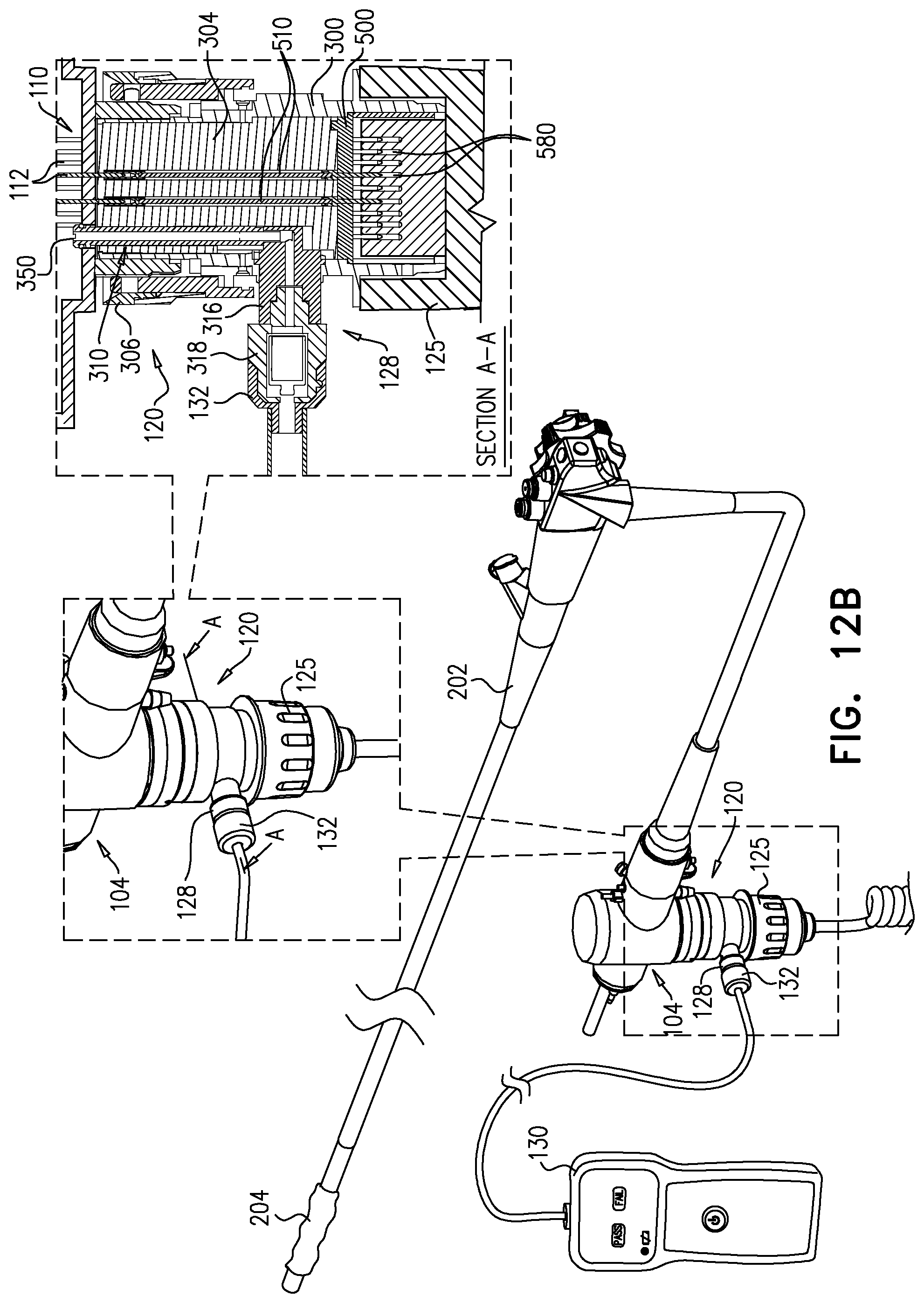
Reference is now made FIGS. 12A and 12B, which are simplified illustrations showing two operative orientations of the electro-pneumatic adaptor of FIGS. 3A-3C relative to the leak testing subsystem forming part of the balloon endoscope system of FIG. 2A. In FIG. 12A, it is seen that the electro-pneumatic adaptor 120 is connected to the balloon endoscope 202 and to electro-optic subsystem 126 via connector 125 (FIG. 1) but is entirely disconnected from leak testing subsystem 130.
In FIG. 12B, it is seen that second pneumatic connector element 318 is connected to leak testing subsystem 130 via connector 132, which preferably is bayonet connected to second pneumatic connector element 318 in a conventional manner.
Reference is now made to FIGS. 13A and 13B, which are simplified illustrations showing two operative orientations of the electro-pneumatic adaptor of FIGS. 3A-3C relative to the inflation/deflation subsystem 230 forming part of the balloon endoscope system of FIG. 2B. In FIG. 13A, it is seen that the electro-pneumatic adaptor 120 is connected to the balloon endoscope 202 and to electro-optic subsystem 126 via connector 125 (FIG. 1) but is entirely disconnected from inflation/deflation subsystem 230 and from connector 232.
In FIG. 13B, it is seen that second pneumatic connector element 318 is connected to inflation/deflation subsystem 230 via connector 232, which preferably is bayonet connected to second pneumatic connector element 318 in a conventional manner.
It will be appreciated by persons skilled in the art that the scope of the present invention is not limited by what has been particularly shown and described hereinabove. Rather the scope of the present invention includes the combinations and subcombinations of the features described hereinabove as well as modifications thereof which are not in the prior art.
* * * * *
References
-
medical.olympusamerica.com/products/control/ballooncontrol-unit-obcu
-
-
olympus.nl/medical/en/medical_systems/hidden/downloadJsp.jsp?link=/medical/rmt/media/content/content1/documents1/brochures1/EVIS_EXERA_11_CLV-180_product_brochure_001_V1-en_GB_20000101.pdf
-
fujifilmusa.com/products/medical/endoscopy/endoscopes/specialized-balloons-andovertube/index.html#balloonsspecifications
-
-
-
-
-
D00000
D00001
D00002
D00003
D00004
D00005
D00006
D00007
D00008
D00009
D00010
D00011
D00012

D00013

D00014

D00015

D00016

D00017

D00018

D00019
D00020

D00021

XML
uspto.report is an independent third-party trademark research tool that is not affiliated, endorsed, or sponsored by the United States Patent and Trademark Office (USPTO) or any other governmental organization. The information provided by uspto.report is based on publicly available data at the time of writing and is intended for informational purposes only.
While we strive to provide accurate and up-to-date information, we do not guarantee the accuracy, completeness, reliability, or suitability of the information displayed on this site. The use of this site is at your own risk. Any reliance you place on such information is therefore strictly at your own risk.
All official trademark data, including owner information, should be verified by visiting the official USPTO website at www.uspto.gov. This site is not intended to replace professional legal advice and should not be used as a substitute for consulting with a legal professional who is knowledgeable about trademark law.