Transverse beam for composite floor structure and method of making the same
McCloud , et al. November 10, 2
U.S. patent number 10,829,163 [Application Number 16/100,276] was granted by the patent office on 2020-11-10 for transverse beam for composite floor structure and method of making the same. This patent grant is currently assigned to Wabash National, L.P.. The grantee listed for this patent is Wabash National, L.P.. Invention is credited to Scott M. Lewit, Travis S. McCloud, Ronnal P. Reichard, Scott A. Storz, Andrzej Wylezinski.


View All Diagrams
| United States Patent | 10,829,163 |
| McCloud , et al. | November 10, 2020 |
Transverse beam for composite floor structure and method of making the same
Abstract
A composite floor structure having a plurality of transverse beams. Each transverse beam may include a preform core having a plurality of side surfaces and two end surfaces, and at least one reinforcing layer formed around each of the side surfaces of the preform core.
| Inventors: | McCloud; Travis S. (Cadiz, KY), Storz; Scott A. (Lafayette, IN), Wylezinski; Andrzej (Lafayette, IN), Reichard; Ronnal P. (Melbourne, FL), Lewit; Scott M. (Indialantic, FL) | ||||||||||
|---|---|---|---|---|---|---|---|---|---|---|---|
| Applicant: |
|
||||||||||
| Assignee: | Wabash National, L.P.
(Lafayette, IN) |
||||||||||
| Family ID: | 1000005171812 | ||||||||||
| Appl. No.: | 16/100,276 | ||||||||||
| Filed: | August 10, 2018 |
Prior Publication Data
| Document Identifier | Publication Date | |
|---|---|---|
| US 20190047634 A1 | Feb 14, 2019 | |
Related U.S. Patent Documents
| Application Number | Filing Date | Patent Number | Issue Date | ||
|---|---|---|---|---|---|
| 62543467 | Aug 10, 2017 | ||||
| Current U.S. Class: | 1/1 |
| Current CPC Class: | B32B 27/065 (20130101); B32B 7/12 (20130101); B32B 27/40 (20130101); B32B 5/18 (20130101); B32B 27/12 (20130101); B32B 27/08 (20130101); B32B 7/08 (20130101); B32B 5/12 (20130101); B62D 25/2054 (20130101); B32B 2266/0278 (20130101); B32B 2605/08 (20130101); B32B 2262/101 (20130101) |
| Current International Class: | B62D 25/20 (20060101); B32B 7/08 (20190101); B32B 5/12 (20060101); B32B 27/06 (20060101); B32B 27/08 (20060101); B32B 27/12 (20060101); B32B 7/12 (20060101); B32B 27/40 (20060101); B32B 5/18 (20060101) |
References Cited [Referenced By]
U.S. Patent Documents
| 3557992 | January 1971 | Reeves |
| 3637252 | January 1972 | Vletsker |
| 4418507 | December 1983 | Roberts et al. |
| 4685720 | August 1987 | Oren |
| 4758299 | July 1988 | Burke |
| 4976490 | December 1990 | Gentle |
| 5403063 | April 1995 | Sjostedt et al. |
| 5429066 | July 1995 | Lewit et al. |
| 5507405 | April 1996 | Thomas |
| 5562981 | October 1996 | Ehrlich |
| 5664518 | September 1997 | Lewit et al. |
| 5700118 | December 1997 | Bennett |
| 5765639 | June 1998 | Muth |
| 5772276 | June 1998 | Fetz et al. |
| 5800749 | September 1998 | Lewit et al. |
| 5802984 | September 1998 | Thoman |
| 5830308 | November 1998 | Reichard |
| 5860668 | January 1999 | Hull et al. |
| 5860693 | January 1999 | Ehrlich |
| 5890435 | April 1999 | Thoman |
| 5897818 | April 1999 | Lewit et al. |
| 5908591 | June 1999 | Lewit et al. |
| 5916093 | June 1999 | Fecko |
| 5979684 | November 1999 | Ohnishi |
| 5992117 | November 1999 | Schmidt |
| 6004492 | December 1999 | Lewit et al. |
| 6013213 | January 2000 | Lewit et al. |
| 6076693 | June 2000 | Reiter |
| 6082810 | July 2000 | Bennett |
| 6092472 | July 2000 | Thoman |
| 6199939 | March 2001 | Ehrlich |
| 6206669 | March 2001 | Lewit et al. |
| 6220651 | April 2001 | Ehrlich |
| 6227125 | May 2001 | Schroeder |
| 6247747 | June 2001 | Kawanomoto |
| 6318794 | November 2001 | Berube |
| 6349988 | February 2002 | Foster |
| 6374546 | April 2002 | Fecko |
| 6496190 | December 2002 | Driemeyher et al. |
| 6497190 | December 2002 | Lewit |
| 6505883 | January 2003 | Ehrlich |
| 6543469 | April 2003 | Lewit et al. |
| 6615741 | September 2003 | Fecko |
| 6626622 | September 2003 | Zubko |
| 6688835 | February 2004 | Buher |
| 6723273 | April 2004 | Johnson et al. |
| 6740381 | May 2004 | Day et al. |
| 6745470 | June 2004 | Foster et al. |
| 6755998 | June 2004 | Reichard et al. |
| 6761840 | July 2004 | Fecko |
| 6824341 | November 2004 | Ehrlich |
| 6843525 | January 2005 | Preisler |
| 6854791 | February 2005 | Jaggi |
| 6863339 | March 2005 | Bohm |
| 6869561 | March 2005 | Johnson et al. |
| 6877940 | April 2005 | Nelson |
| 6893075 | May 2005 | Fenton et al. |
| 6911252 | June 2005 | Lewit et al. |
| 6986546 | January 2006 | Ehrlich |
| 7000978 | February 2006 | Messano |
| 7025166 | April 2006 | Thomas |
| 7025408 | April 2006 | Jones et al. |
| 7069702 | July 2006 | Ehrlich |
| 7134820 | November 2006 | Ehrlich |
| 7182396 | February 2007 | Taylor |
| 7219952 | May 2007 | Taylor |
| 7264305 | September 2007 | Kuriakose |
| 7353960 | April 2008 | Seiter |
| 7407216 | August 2008 | Taylor |
| 7434520 | October 2008 | Zupancich |
| 7451995 | November 2008 | Bloodworth et al. |
| 7461888 | December 2008 | Brown |
| 7517005 | April 2009 | Kuriakose |
| 7575264 | August 2009 | Solomon |
| 7578534 | August 2009 | Wuerfel, III |
| 7578541 | August 2009 | Layfield |
| 7587984 | September 2009 | Zupancich |
| 7588286 | September 2009 | Lewallen |
| 7594474 | September 2009 | Zupancich |
| 7608313 | October 2009 | Solomon |
| 7621589 | November 2009 | Gerome |
| 7704026 | April 2010 | Roush |
| 7722112 | May 2010 | Ehrlich |
| 7748172 | July 2010 | Zupancich |
| 7762618 | July 2010 | Lewallen |
| 7790076 | September 2010 | Seiter |
| 7829165 | November 2010 | Grandominico et al. |
| 7887120 | February 2011 | Boivin |
| 7901537 | March 2011 | Jones |
| 7905072 | March 2011 | Verhaeghe |
| 7914034 | March 2011 | Roush |
| 7931328 | April 2011 | Lewallen |
| 8016322 | September 2011 | Keehan |
| 8056960 | November 2011 | Brown |
| 8186747 | May 2012 | Bloodworth et al. |
| 8263217 | September 2012 | Verhaeghe |
| 8342588 | January 2013 | Skaradzinski |
| 8448989 | May 2013 | Verhaeghe |
| 8474171 | July 2013 | Ludwick |
| 8696048 | April 2014 | Griffin et al. |
| 8757704 | June 2014 | Zhao et al. |
| 8814255 | August 2014 | Yamaji et al. |
| 8876193 | November 2014 | Kunkel et al. |
| 8950144 | February 2015 | Padmanabhan |
| 9051014 | June 2015 | Lookebill et al. |
| 9138943 | September 2015 | Weinberg |
| 9138974 | September 2015 | Weinberg |
| 9138975 | September 2015 | Weinberg |
| 9174656 | November 2015 | Heitmeyer |
| 9199440 | December 2015 | Weinberg |
| 9205635 | December 2015 | Weinberg |
| 9260117 | February 2016 | Vande Sands |
| 9339987 | May 2016 | Weinberg |
| 9371468 | June 2016 | Lewit |
| 9409607 | August 2016 | Osten |
| 9434421 | September 2016 | Lu |
| 9499203 | November 2016 | Finley |
| 9566769 | February 2017 | Weinberg |
| 9604677 | March 2017 | McKinney |
| 9650003 | May 2017 | Owens |
| 9708009 | July 2017 | Vance |
| 9738050 | August 2017 | Lee |
| 9744753 | August 2017 | Sheffield |
| 9815501 | November 2017 | McCormack |
| 9827750 | November 2017 | Lookebill |
| 9828164 | November 2017 | Denson |
| 9878744 | January 2018 | Lu |
| 9884660 | February 2018 | Fenton |
| 9884661 | February 2018 | Fenton |
| 9889637 | February 2018 | Weinberg |
| 2001/0011832 | August 2001 | Ehrlich |
| 2005/0194381 | September 2005 | Zupancich |
| 2005/0241253 | November 2005 | Song et al. |
| 2006/0065152 | March 2006 | Heitmeyer |
| 2006/0108361 | May 2006 | Seiter |
| 2006/0121244 | June 2006 | Godwin |
| 2006/0123725 | June 2006 | Godwin |
| 2006/0158005 | July 2006 | Brown |
| 2006/0179733 | August 2006 | Padmanabhan |
| 2006/0201081 | September 2006 | Godwin |
| 2006/0219129 | October 2006 | Jarvis |
| 2007/0119850 | May 2007 | Seiter |
| 2007/0132278 | June 2007 | Lester et al. |
| 2007/0160793 | July 2007 | Cageao |
| 2007/0194602 | August 2007 | Ehrlich |
| 2007/0216197 | September 2007 | Wuerfel, III |
| 2007/0250025 | October 2007 | Sams |
| 2008/0290057 | November 2008 | Zupancich |
| 2009/0126600 | May 2009 | Zupancich |
| 2009/0278386 | November 2009 | Ehrlich |
| 2010/0101876 | April 2010 | Misencik |
| 2010/0109309 | May 2010 | Kootstra |
| 2011/0095574 | April 2011 | Brown |
| 2011/0204611 | August 2011 | Ziegler |
| 2013/0207413 | August 2013 | Lookebill et al. |
| 2014/0199551 | July 2014 | Lewit |
| 2014/0262011 | September 2014 | Lewit et al. |
| 2014/0300134 | October 2014 | Gerst |
| 2015/0054311 | February 2015 | Marchesano et al. |
| 2015/0076861 | March 2015 | Padmanabhan |
| 2015/0137560 | May 2015 | Presiler |
| 2015/0158532 | June 2015 | Ayuzawa |
| 2015/0203160 | July 2015 | Peterson et al. |
| 2017/0057561 | March 2017 | Fenton |
| 2017/0166263 | June 2017 | McKinney |
| 2017/0210317 | July 2017 | Owens |
| 2017/0240216 | August 2017 | Bauer |
| 2017/0240217 | August 2017 | Storz |
| 2017/0241134 | August 2017 | McCloud |
| 2017/0247063 | August 2017 | Banerjee |
| 2017/0282499 | October 2017 | LaRocco |
| 2017/0334489 | November 2017 | Shin |
| 2018/0037151 | February 2018 | Bauer et al. |
| 713260 | Nov 1999 | AU | |||
| 1329818 | May 1994 | CA | |||
| 2181750 | Jan 1997 | CA | |||
| 2199584 | Sep 1997 | CA | |||
| 2253308 | Nov 1997 | CA | |||
| 2551863 | Mar 1998 | CA | |||
| 2219312 | Apr 1998 | CA | |||
| 2242467 | Jul 1999 | CA | |||
| 2261384 | Aug 1999 | CA | |||
| 2265405 | Jan 2000 | CA | |||
| 2275848 | Dec 2000 | CA | |||
| 2382578 | Mar 2001 | CA | |||
| 2455957 | May 2004 | CA | |||
| 2768878 | Mar 2005 | CA | |||
| 2811134 | Apr 2006 | CA | |||
| 2529762 | Jun 2006 | CA | |||
| 2650992 | Nov 2006 | CA | |||
| 2528558 | May 2007 | CA | |||
| 2565510 | Aug 2007 | CA | |||
| 2604282 | Mar 2008 | CA | |||
| 2689745 | Jul 2009 | CA | |||
| 2689746 | Jul 2009 | CA | |||
| 2689747 | Jul 2009 | CA | |||
| 2689748 | Jul 2009 | CA | |||
| 2689749 | Jul 2009 | CA | |||
| 2689751 | Jul 2009 | CA | |||
| 2797778 | Jul 2009 | CA | |||
| 2802907 | Jul 2009 | CA | |||
| 2788047 | Aug 2011 | CA | |||
| 2763094 | Jul 2012 | CA | |||
| 2848174 | Oct 2014 | CA | |||
| 2894059 | Dec 2015 | CA | |||
| 2807710 | May 2016 | CA | |||
| 2977131 | Sep 2016 | CA | |||
| 2958805 | Aug 2017 | CA | |||
| 2958838 | Aug 2017 | CA | |||
| 2958839 | Aug 2017 | CA | |||
| 2617169 | Oct 2013 | DE | |||
| 2660119 | Jun 2013 | EP | |||
| 06293233 | Oct 1994 | JP | |||
Other References
|
Black Sara "Structural adhesives Part I: Industrial" CompositesWorld posted Apr. 11, 2016 7 pages. cited by applicant . CMS North America Inc. "Transportation: Refrigerated Semi-trailers Trailers & Vans" available online at http:www.cmsna.com13_transportation_refrigerated_semi_trailers_trailers_v- ans.php on or before Jul. 2, 2014 2 pages. cited by applicant . North American Composites Virtual Engineered Composites (VEC) Article available online at http:www.nacomposites.comdelivering-performancepage.asp?issueid=7&page=co- ver Fall 2006 4 pages. cited by applicant . Reichard Dr. Ronnal P. "Composites in Theme Parks: From the perspective of a contractor--trouble shooter--enthusiast!" presented at Florida Institute of Technology at least as early as 1999 37 pages. cited by applicant . Lightweight Structures B.V. "ColdFeather: lightweight composite isothermal trailer" available online at http:www.lightweight-structures.comcoldfeather-lightweight-composite-isot- hermal-trailerindex.html at least as early as Jun. 18, 2015 6 pages. cited by applicant . Expedition Portal "Truck Camper Construction Costs?" available online at http:www.expeditionportal.comforumthreads12486-Truck-Camper-Construction-- Costs at least as early as Jun. 18, 2015 5 pages. cited by applicant . Griffiths Bob "Rudder Gets New Twist with Composites" CompositesWorld posted Aug. 1, 2006 4 pages. cited by applicant . Morey Bruce "Advanced Technologies Supplement: Processes Reduce Composite Costs" Advanced Manufacturing posted Apr. 1, 2007 7 pages. cited by applicant . NetCompositesNow.com "Twisted Composites Rudders" available online at http:www.netcomposites.comnewstwisted-composites-rudders3202 as early as Aug. 11, 2005 3 pages. cited by applicant . Eric Green Associates.com "Composite Rudders Take Shape for U.S. Navy" available online at http:www.ericgreeneassociates.comimagesComposite_Twisted_Rudder.pdf accessed as early as Jul. 13, 2014 7 pages. cited by applicant . Seaver Mark and Trickey Stephen "Underwater Blast Loading of a Composite Twisted Rudder with FBGS" dated Apr. 14, 2008 19th International Conference on Optical Fibre Sensors 2 pages. cited by applicant . Scott Bader Group Companies Crystic "Composites Handbook" 100 pages. cited by applicant . Kedward Keith and Whitney James Delaware Composites Design Encyclopedia "Design Studies" vol. 5 1990 preview version available at https:books.google.combooks?id=9-KYOm81MWEC&printsec=frontcover#v=onepage- &q&f=false 17 pages. cited by applicant . Zweben Carl Handbook of Materials Selection "Chapter 12: Composite Materials" 2002 preview version available at https:books.google.combooks?id=gWg-rchM700C&printsec=frontcover#v=onepage- &q&f=false 47 pages. cited by applicant . Johnson Truck Bodies Blizzard Series brochure accessed as early as Aug. 1, 2014 8 pages. cited by applicant . International Trucking Shows "True Composites Platform Highlight of International Trucking Show" Aug. 1992 1 page. cited by applicant . Composite Twisted Rudder TCC Meeting 2008 handout 32 pages. cited by applicant . Composite Marine Control Surface installed on USS Pioneer (MCM 9) May 1997 13 pages. cited by applicant . TrailerBody Builders "More Emphasis on Less Weight" available at http:trailer-bodybuilders.comtrailersmore-emphasis-less-weight May 1, 2008 5 pages. cited by applicant. |
Primary Examiner: Dayoan; D Glenn
Assistant Examiner: Bonifazi; Melissa Ann
Attorney, Agent or Firm: Faegre Drinker Biddle & Reath LLP
Parent Case Text
CROSS REFERENCE TO RELATED APPLICATION
This application claims priority to U.S. Provisional Patent Application Ser. No. 62/543,467, filed Aug. 10, 2017, the disclosure of which is hereby expressly incorporated by reference herein in its entirety.
Claims
What is claimed is:
1. A composite floor structure for use in a cargo vehicle having a front end, a rear end, and a longitudinal axis extending between the front and rear ends, the composite floor structure comprising: a plurality of transverse beams, each transverse beam being constructed of a composite material and having an upper wall, a first side wall, a second side wall, and a lower wall, the plurality of transverse beams arranged perpendicular to the longitudinal axis and in direct contact with one another such that the first side wall of one transverse beam directly contacts the second side wall of an immediately adjacent transverse beam; wherein the lower walls of the plurality of transverse beams cooperate to provide a substantially smooth and continuous surface that supports a plurality of longitudinal beams that extend parallel to the longitudinal axis and perpendicular to the plurality of transverse beams; wherein the composite floor structure further comprises an underlayment positioned between the plurality of transverse beams and the plurality of longitudinal beams.
2. The composite floor structure of claim 1, wherein the upper walls of the plurality of transverse beams cooperate to provide a substantially smooth and continuous surface that supports a platform having a flat upper surface configured to support cargo in the cargo vehicle.
3. The composite floor structure of claim 1, wherein each transverse beam is constructed of a preform core with at least one reinforcing layer wrapped around the preform core.
4. The transverse beam of claim 1, wherein the first and second side walls of each transverse beam are parallel to each other.
5. A transverse beam comprising: a preform core having a plurality of side surfaces arranged in a parallelogram; and a primary reinforcing layer formed around each of the side surfaces of the preform core, the primary reinforcing layer including two tabs folded onto one another and sized to cover at least one of the plurality of side surfaces of the preform core.
6. The transverse beam of claim 5 further comprising an additional reinforcing layer wound at least partially around both the preform core and the primary reinforcing layer.
7. The transverse beam of claim 5 further comprising a first additional reinforcing layer oriented vertically parallel to at least one side surface of the preform core.
8. The transverse beam of claim 7 further comprising a second additional reinforcing layer wound at least partially around the preform core, the primary reinforcing layer, and the first additional reinforcing layer.
9. The transverse beam of claim 5, wherein the preform core is constructed of foam.
10. The transverse beam of claim 5, wherein the transverse beam includes an upper surface and a lower surface, the transverse beam being of substantially constant width from the upper surface to the lower surface.
11. The transverse beam of claim 5, wherein the two tabs of the primary reinforcing layer are impregnated with a resin and are in contact with the preform core.
12. The transverse beam of claim 5, wherein the preform core has a shape of one of a square or a rectangle across its length.
13. The transverse beam of claim 7, wherein the two tabs of the primary reinforcing layer and the first additional reinforcing layer cover opposing side surfaces of the preform core.
14. A transverse beam comprising: a preform core having a plurality of side surfaces; a primary reinforcing layer formed around at least three side surfaces of the preform core; and an additional reinforcing layer sized to cover at least one side of the preform core separate from the at least three side surfaces covered by the primary reinforcing layer, the primary reinforcing layer and the additional reinforcing layer each having a first edge and a second edge, the first edge of the primary reinforcing layer being adjacent to the first edge of the additional reinforcing layer and the second edge of the primary reinforcing layer being adjacent to the second edge of the additional reinforcing layer.
15. The transverse beam of claim 14, wherein the first edge of the primary reinforcing layer and the first edge of the additional reinforcing layer and the second edge of the primary reinforcing layer and the second edge of the additional reinforcing layer are both directly coupled together.
16. The transverse beam of claim 15, wherein the first edges and second edges are coupled together using at least one of a structural adhesive, a thread, and at least one staple.
17. The transverse beam of claim 14, wherein the primary reinforcing layer and the additional reinforcing layer are indirectly coupled together through the preform core.
18. The transverse beam of claim 14, wherein the additional reinforcing layer is a fiber stitched cloth.
19. The transverse beam of claim 14, wherein the first edge of the primary reinforcing layer and the first edge of the additional reinforcing layer are cut edges adjacent one another, and the second edge of the primary reinforcing layer and the second edge of the additional reinforcing layer are cut edges adjacent one another.
20. A transverse beam comprising: a preform core having a plurality of side surfaces; and a primary reinforcing layer formed around each of the side surfaces of the preform, wherein the primary reinforcing layer has a first edge and a second edge, the first and second edges being coupled together.
21. The transverse beam of claim 20, wherein the first and second edges are coupled together using at least one of a thread, a structural adhesive, and the at least one staple.
22. The transverse beam of claim 21, wherein the first and second edges are sewn together using the thread.
23. The transverse beam of claim 20, wherein the first edge and the second edge are coupled together along an edge of the preform core.
Description
FIELD OF THE DISCLOSURE
The present disclosure relates generally to floor structures and methods of making the same. More particularly, the present disclosure relates to transverse beams for floor structures made of composite materials for use in cargo vehicles and other applications and methods of making the same.
BACKGROUND OF THE DISCLOSURE
Cargo vehicles are used in the transportation industry for transporting many different types of cargo. Cargo vehicles may be constructed using composite materials, which may lead to an absence of or reduction in metallic and wood materials and associated advantages, including simplified construction, thermal efficiency, reduced water intrusion and corrosion, and improved fuel efficiency through weight reduction, for example. However, composite materials, in some locations and arrangements, may have reduced strength as compared to metallic and/or wood materials. Thus, strengthened floor structures are desired.
SUMMARY OF THE DISCLOSURE
A composite floor structure and method of making the same are disclosed. The composite floor structure may include a platform and a plurality of transverse beams. The composite floor structure may also include at least one longitudinal beam. The composite floor structure may also include an underlayment between the plurality of transverse beams and the at least one longitudinal beam. Some or all of these components may be integrally molded together to form a fiber-reinforced polymer structure. The composite floor structure may be used for cargo vehicles and other applications.
According to an exemplary embodiment of the present disclosure, a composite floor structure for use in a cargo vehicle having a front end, a rear end, and a longitudinal axis extending between the front and rear ends comprises a plurality of transverse beams. Each transverse beam is constructed of a composite material and has an upper wall, a first side wall, a second side wall, and a lower wall. The plurality of transverse beams are arranged perpendicular to the longitudinal axis and in direct contact with one another such that the first side wall of one transverse beam directly contacts the second side wall of an immediately adjacent transverse beam.
According to another exemplary embodiment of the present disclosure, a transverse beam comprises a preform core having a plurality of side surfaces, and a primary reinforcing layer formed around each of the side surfaces of the preform core. The primary reinforcing layer includes two tabs configured to fold onto one another and sized to cover at least one of the plurality of side surfaces of the preform core.
According to yet another exemplary embodiment of the present disclosure, a transverse beam comprises a preform core having a plurality of side surfaces, a primary reinforcing layer formed around at least three side surfaces of the preform core, and an additional reinforcing layer sized to cover at least one side of the preform core separate from the at least three side surfaces covered by the primary reinforcing layer. The primary reinforcing layer and the additional reinforcing layer each having a first edge and a second edge, the first edge of the primary reinforcing layer being adjacent the first edge of the additional reinforcing layer and the second edge of the primary reinforcing layer being adjacent the second edge of the additional reinforcing layer.
According to still yet another exemplary embodiment of the present disclosure, a transverse beam comprises a preform core having a plurality of side surfaces, and a primary reinforcing layer formed around each of the side surfaces of the preform, where the primary reinforcing layer has a first edge and a second edge, the first and second edges being coupled together.
Additional features and advantages of the present invention will become apparent to those skilled in the art upon consideration of the following detailed description of the illustrative embodiments exemplifying the best mode of carrying out the invention as presently perceived.
BRIEF DESCRIPTION OF THE DRAWINGS
The foregoing aspects and many of the intended advantages of this invention will become more readily appreciated as the same becomes better understood by reference to the following detailed description when taken in conjunction with the accompanying drawings.
FIG. 1 shows a top perspective view of an exemplary composite floor structure of the present disclosure, the composite floor structure including a platform, a plurality of transverse beams, a plurality of longitudinal beams, and an underlayment;
FIG. 2 shows a rear end elevational view of the composite floor structure of FIG. 1;
FIG. 3 shows a left side elevational view of the composite floor structure of FIG. 1;
FIG. 4 shows a bottom plan view of the composite floor structure of FIG. 1, with a portion of the underlayment removed to show the plurality of transverse beams;
FIG. 5 shows an exploded side view of the platform of FIG. 1;
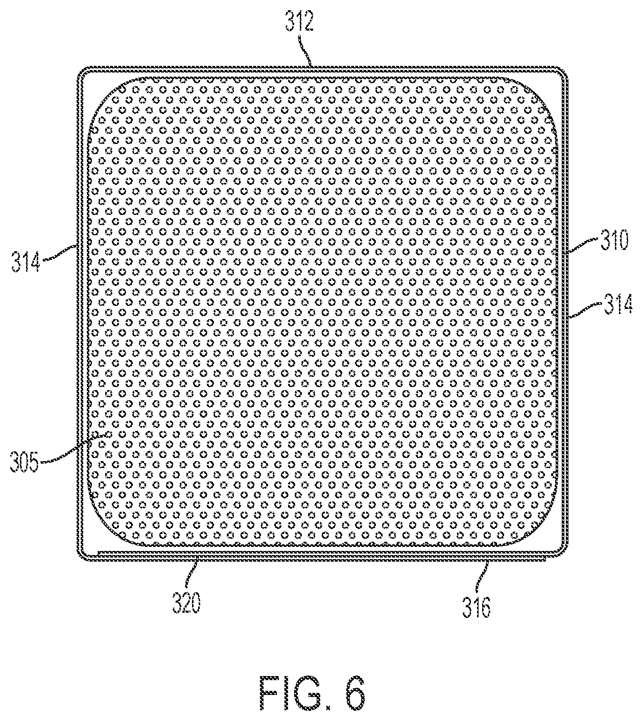
FIG. 6 shows an end view of a first embodiment of a transverse beam of the present disclosure;
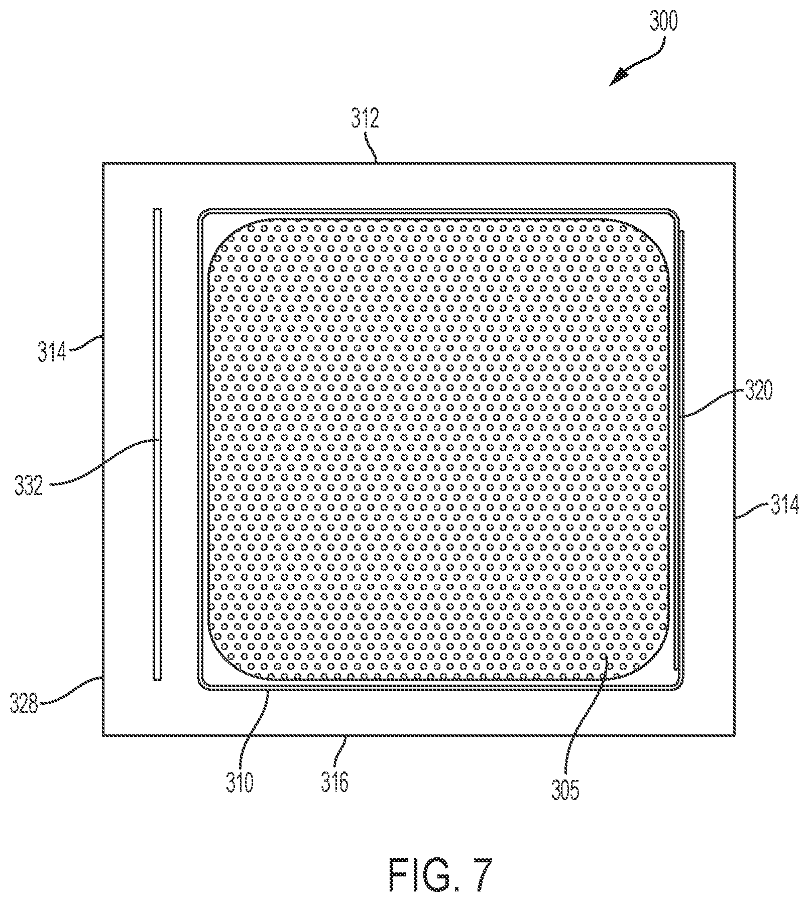
FIG. 7 shows an end view the transverse beam of FIG. 7 with additional reinforcing material;
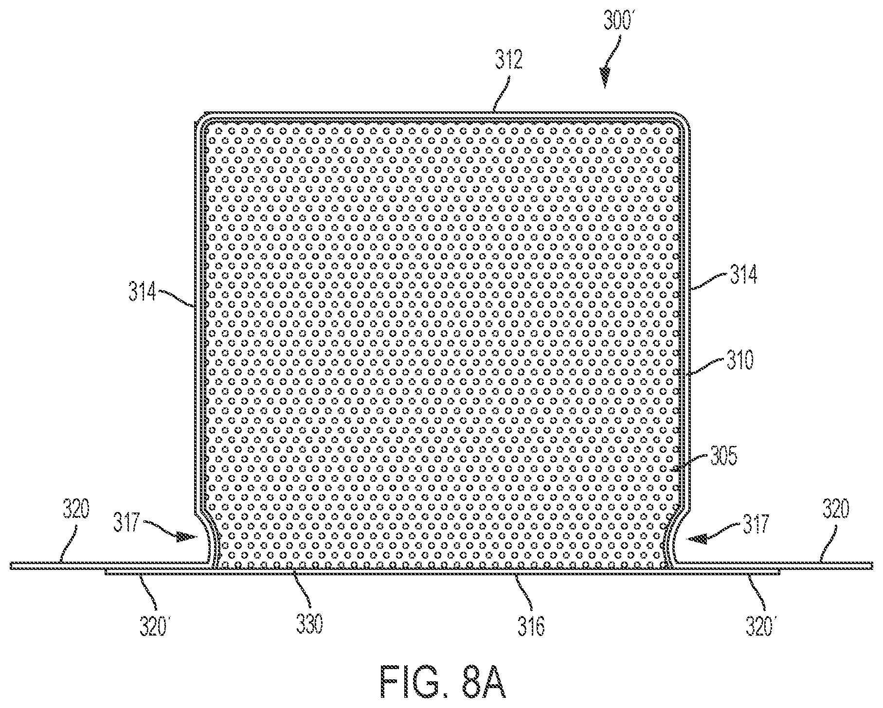
FIG. 8A shows an end view of a second embodiment of a transverse beam of the present disclosure with tabs attached;
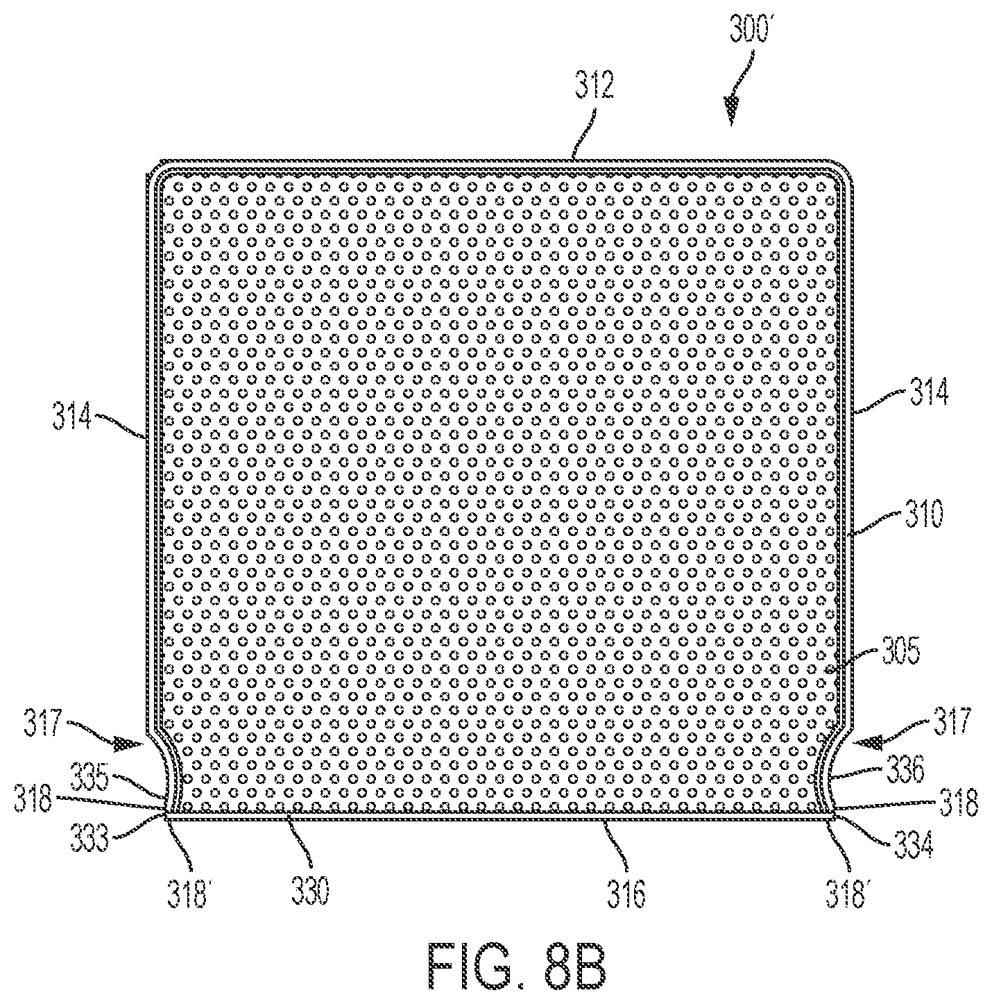
FIG. 8B shows an end view of the second embodiment of FIG. 8A with tabs removed providing exposed cut edges;
FIG. 8C shows an end view of the second embodiment of FIG. 8A with coupled edges;
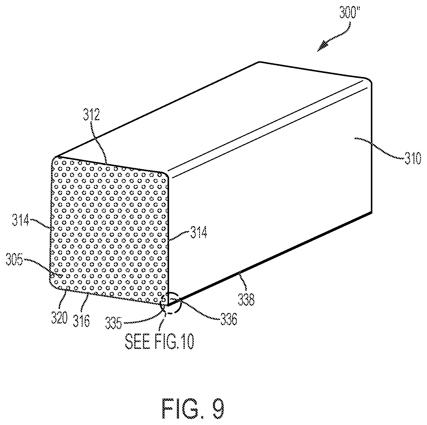
FIG. 9 shows an end view of a third embodiment of a transverse beam of the present disclosure;
FIG. 10 shows a detailed view of the area circled in FIG. 9;
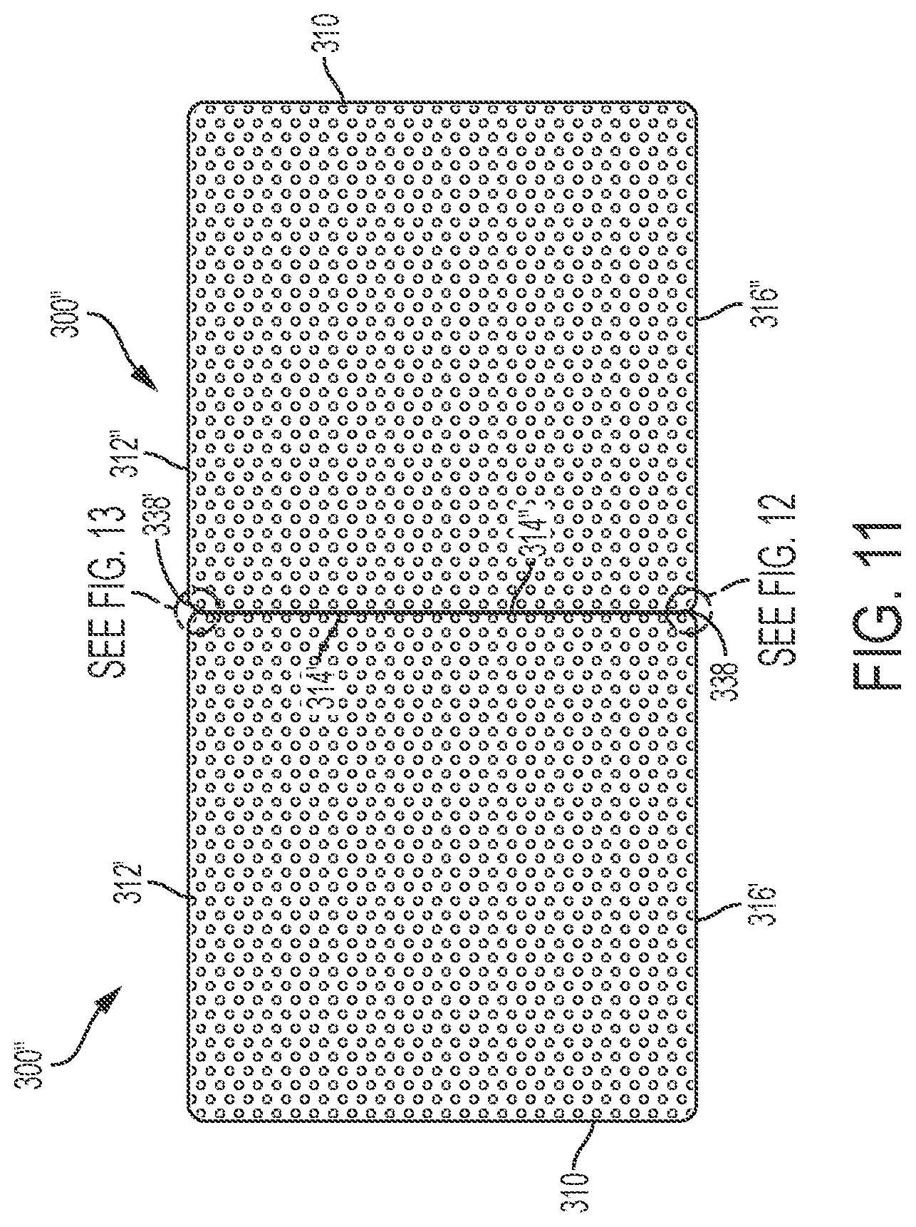
FIG. 11 shows an end view of multiple transverse beams of FIG. 9 positioned next to each other;
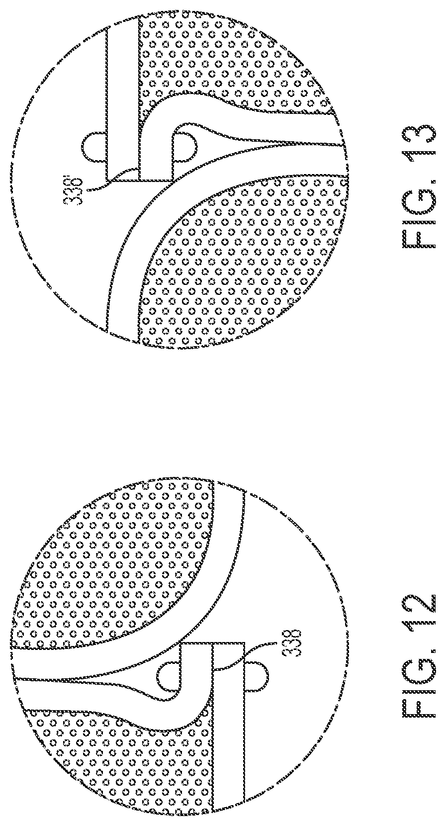
FIG. 12 shows a detailed view of the area circled in FIG. 11;
FIG. 13 shows a detailed view of the area circled in FIG. 11; and
FIG. 14 shows an exploded perspective view of the longitudinal beam of FIG. 1.
Corresponding reference characters indicate corresponding parts throughout the several views. Although the drawings represent embodiments of various features and components according to the present disclosure, the drawings are not necessarily to scale and certain features may be exaggerated in order to better illustrate and explain the present disclosure. The exemplification set out herein illustrates an embodiment of the invention, and such an exemplification is not to be construed as limiting the scope of the invention in any manner.
DETAILED DESCRIPTION OF THE DRAWINGS
For the purposes of promoting an understanding of the principals of the invention, reference will now be made to the embodiments illustrated in the drawings, which are described below. The embodiments disclosed below are not intended to be exhaustive or limit the invention to the precise form disclosed in the following detailed description. Rather, the embodiments are chosen and described so that others skilled in the art may utilize their teachings. It will be understood that no limitation of the scope of the invention is thereby intended. The invention includes any alterations and further modifications in the illustrative devices and described methods and further applications of the principles of the invention which would normally occur to one skilled in the art to which the invention relates.
1. Floor Structure
Referring initially to FIGS. 1-5, a composite floor structure 100 is shown. In certain embodiments, the composite floor structure 100 may be used in cargo vehicles for supporting and transporting cargo, including semi trailers (e.g., refrigerated semi trailers, dry freight semi trailers, flatbed semi trailers), other trailers, box trucks or vans, and the like. In other embodiments, the composite floor structure 100 may be used to construct dump trucks or dump trailers, boat docks, mezzanines, storage units, or temporary shelters, for example. Accordingly, those skilled in the art will appreciate that the present invention may be implemented in a number of different applications and embodiments and is not specifically limited in its application to the particular embodiments depicted herein.
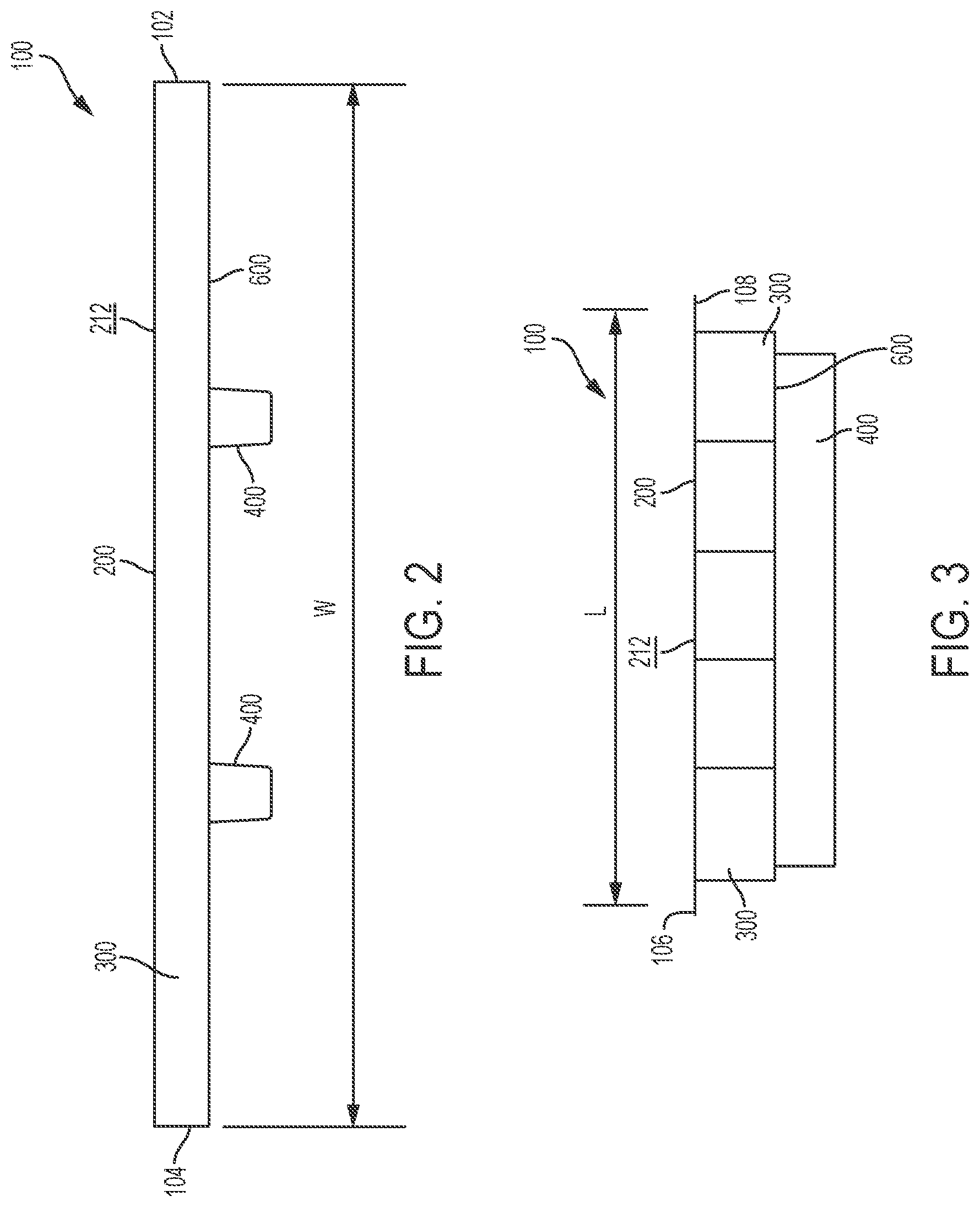
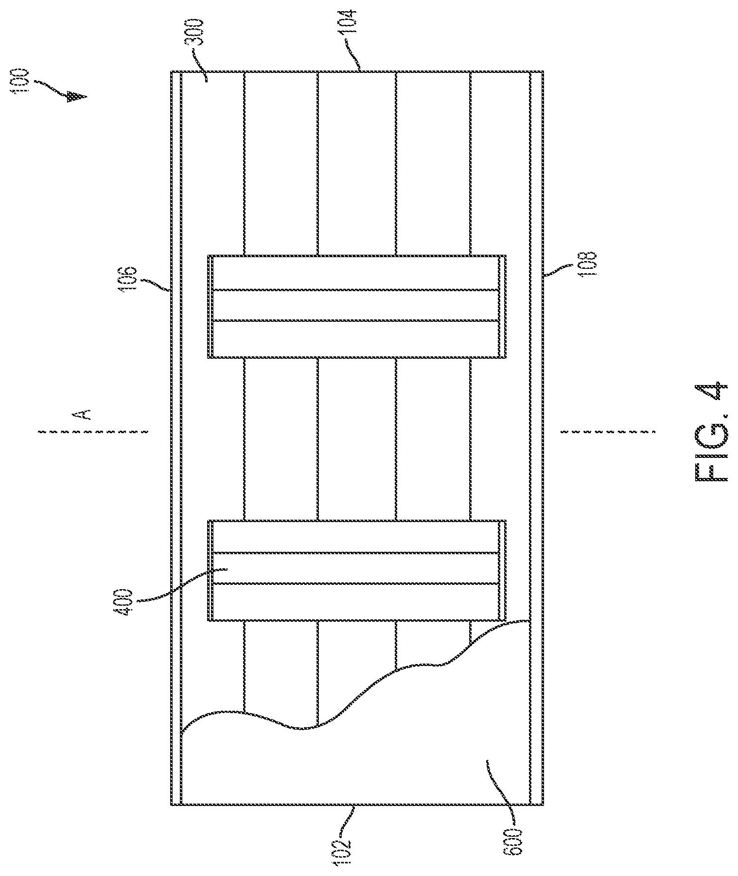
The illustrative composite floor structure 100 is generally rectangular in shape, although this shape may vary. As shown in FIG. 2, the composite floor structure 100 has a width W between a right side 102 and a left side 104. As shown in FIG. 3, the composite floor structure 100 has a length L between a front end 106 and a rear end 108. The length L and the width W may vary depending on the needs of the particular application. As shown in FIG. 4, the composite floor structure 100 also has a longitudinal axis A that extends through the front end 106 and the rear end 108. In various embodiments, floor structure 100 may have curvature along the longitudinal axis A.
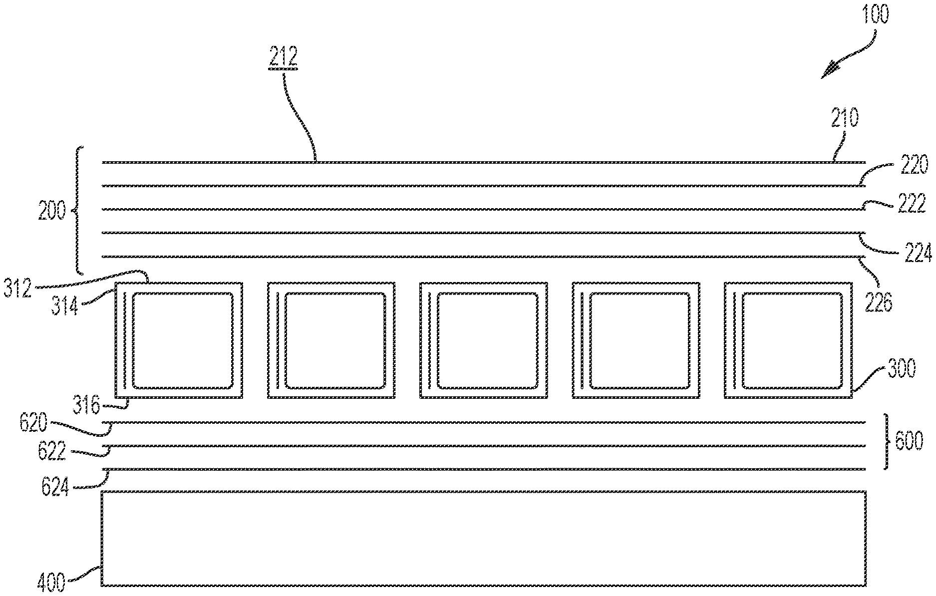
The illustrative composite floor structure 100 includes a deck or platform 200, a plurality of transverse beams 300 extending from the right side 102 to the left side 104 beneath the platform 200, and a plurality of longitudinal beams 400 extending from the front end 106 to the rear end 108 beneath the transverse beams 300. As shown in FIG. 4, the transverse beams 300 extend perpendicular to the longitudinal axis A, and the longitudinal beams 400 extend parallel to the longitudinal axis A. As shown in FIG. 5, the composite floor structure 100 may also include an underlayment 600 located below transverse beams 300 and above longitudinal beams 400 and parallel to platform 200.
In the illustrated embodiment of FIGS. 1-5, the composite floor structure 100 includes five transverse beams 300 and two longitudinal beams 400, but the number of beams 300, 400 may vary depending on the needs of the particular application. Also, the size of each beam 300, 400 and the spacing between adjacent beams 300, 400, if any, may vary depending on the needs of the particular application. For example, a relatively large number of closely-spaced beams 300, 400 may be used for high-weight/high-strength applications, whereas a relatively small number of spaced-apart beams 300, 400 may be used for low-weight/low-strength applications.
2. Composite Materials with Reinforcing Layers and/or Structural Preforms
The composite floor structure 100 may be constructed, at least in part, of composite materials. For example, the platform 200, the transverse beams 300, the longitudinal beams 400, and/or the underlayment 600 of the composite floor structure 100 may be constructed of composite materials. As such, the platform 200, the transverse beams 300, the longitudinal beams 400, and/or the underlayment 600 of the composite floor structure 100 may be referred to herein as composite structures. These composite structures may lack internal metal components. Also, each composite structure may be a single, unitary component, which may be formed from a plurality of layers permanently coupled together. Exemplary composite materials for use in the composite floor structure 100 include fiber-reinforced plastics (FRP), for example carbon-fiber-reinforced plastics (CRP).
Each composite structure may contain one or more reinforcing layers that contains reinforcing fibers and is capable of being impregnated and/or coated with a resin, as discussed in Section 7 below. Suitable fibers include carbon fibers, glass fibers, cellulose, or polymers, for example. The fibers may be present in fabric form, which may be mat, woven, non-woven, or chopped, for example. Exemplary reinforcing layers include chopped fiber fabrics, such as chopped strand mats (CSM), and continuous fiber fabrics, such as 0.degree./90.degree. fiberglass fabrics, +45.degree./-45.degree. fiberglass fabrics, +60.degree./-60.degree. fiberglass fabrics, 0.degree. warp unidirectional fiberglass fabrics, and other stitched fiber fabrics, for example. Such fabrics are commercially available from Vectorply Corporation of Phenix City, Ala.
According to an exemplary embodiment of the present disclosure, a plurality of different reinforcing materials may be stacked together and used in combination. For example, a chopped fiber fabric (e.g., CSM) may be positioned adjacent to a continuous fiber fabric. In this stacked arrangement, the chopped fibers may help support and maintain the adjacent continuous fibers in place, especially around corners or other transitions. Also, the chopped fibers may serve as a web to resist column-type loads in compression, while the adjacent continuous fibers may resist flange-type loads in compression. Adjacent reinforcing layers may be stitched or otherwise coupled together to simplify manufacturing, to ensure proper placement, and to prevent shifting and/or bunching.
Also, certain composite structures may contain a structural support or preform. The preform may have a structural core that has been covered with an outer fabric layer or skin. The core may be extruded, pultruded, or otherwise formed into a desired shape and cut to a desired length. In an exemplary embodiment, the core is a polyurethane foam material or another foam material, and the outer skin is a spun bond polyester material. Exemplary preforms include PRISMA.RTM. preforms provided by Compsys, Inc. of Melbourne, Fla. Advantageously, in addition to its structural effect, the foam core may have an insulating effect in certain applications, including refrigerated trucking applications. Both the core and the outer skin may be selected to accommodate the needs of the particular application. For example, in areas of the preform requiring more strength and/or insulation, a low-density foam may be replaced with a high-density foam or a hard plastic block.
3. Platform
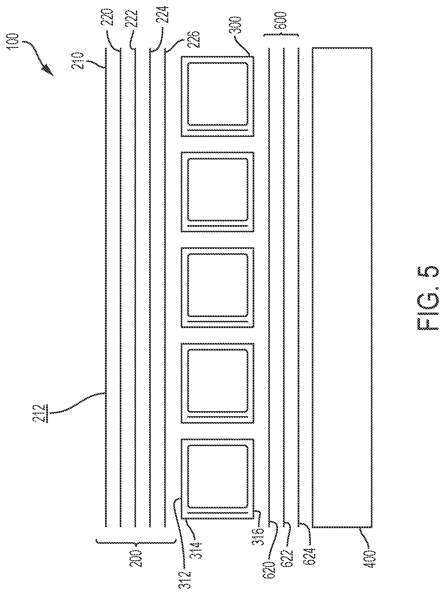
Referring next to FIG. 5, the platform 200 may be constructed from a plurality of layers permanently coupled or laminated together. From top to bottom in FIG. 5, the illustrative platform 200 includes a top layer 210 and four reinforcing layers 220, 222, 224, 226, although the number, types, and locations of these layers may vary depending on the needs of the particular application.
The top layer 210 of the platform 200 defines a flat upper surface 212 for supporting cargo or other objects. According to an exemplary embodiment of the present disclosure, the top layer 210 is a 1.5 ounce/yard.sup.2 chopped fiber fabric (CSM) polymer. In other embodiments, the top layer 210 is a resin, gelcoat, metal (e.g., aluminum, stainless steel), polymer, wood, or pultrusion layer. The top layer 210 may be integrally molded with or otherwise applied to the reinforcing layers 220, 222, 224, 226, such as using structural adhesive, mechanical fasteners (e.g., bolts, rivets), or a spray coating process.
In various embodiments, the top layer 210 is a metal (e.g., aluminum, stainless steel) layer or includes a metal upper surface 212. The upper surface 212 of the metal may be completely flat or textured (e.g., dimpled or ridged) to provide a slip-resistant surface. The top layer 210 may also define channels (i.e., ducts), and such channels may extend through the interior of top layer 210 or across a surface (e.g., upper surface 212) of top layer 210. The top layer 210 may be extruded or otherwise formed into a desired width and cut to a desired length. An exemplary method for attaching top layer 210 during the molding process using one or more co-cure adhesives is disclosed in U.S. patent application Ser. No. 15/439,789, titled "Composites Formed from Co-Cure Adhesive," the disclosure of which is hereby expressly incorporated by reference herein in its entirety.
To accommodate different loads on the platform 200, each reinforcing layer 220, 222, 224, 226 may be unique to provide a combination of different fiber types, sizes, and/or orientations across the platform 200. In an exemplary embodiment, reinforcing layer 220 is a 0.degree. unidirectional fiberglass fabric with the 0.degree. direction of the fabric being oriented in the longitudinal direction of the composite floor structure 100 (i.e., parallel to the longitudinal axis A of FIG. 4) for added strength in the longitudinal direction, specifically E-LM 1810, reinforcing layer 222 is a 0.degree./90.degree. fiberglass fabric, specifically E-LTM 3610, reinforcing layer 224 is a random-orientation chopped fiber fabric, specifically 3.0 ounce/yard.sup.2 CSM, and reinforcing layer 226 is a 0.degree./90.degree. fiberglass fabric, specifically E-LTM 2408. Additional disclosure regarding the reinforcing layers 220, 222, 224, 226 is set forth in Section 2 above.
4. Transverse Beams
Referring next to FIGS. 5-13, each transverse beam 300 may be constructed from a plurality of layers permanently coupled or laminated together such that each transverse beam 300 has an upper wall 312, side walls 314, and a lower wall 316. As shown in FIGS. 1-5, the transverse beams 300 may be placed side-by-side in direct contact with one another, such that the left side wall 314 of one transverse beam 300 directly contacts the right side wall 314 of the immediately adjacent transverse beam 300. This arrangement may provide stiffness and resistance to bending and deflection in the transverse direction. To facilitate this side-by-side contact without forming spaces or gaps therebetween, the side walls 314 may be parallel to each other. Thus, an exemplary transverse beam 300 may have a rectangular shape, a square shape, or another suitable parallelogram shape across its length. In this side-by-side arrangement of FIGS. 1-5, the upper walls 312 of transverse beams 300 may cooperate to provide a substantially smooth and continuous surface for platform 200, and the lower walls 316 of transverse beams 300 may cooperate to provide a substantially smooth and continuous surface for longitudinal beams 400 and/or underlayment 600.
a. First Embodiment
With reference to FIGS. 6 and 7, a first illustrative transverse beam 300 of the present disclosure includes a primary reinforcing layer 310 with two tabs 320 wrapped around a preform core 305. Optionally, transverse beam 300 may include one or more additional reinforcing layers or sheets 328, 332, as shown in FIG. 7, although the number, types, and locations of reinforcing layers may vary depending on the needs of the particular application. Each reinforcing layer 310, 328, 332 may be unique to provide a combination of different fiber types, sizes, and/or orientations across the transverse beam 300. Additional disclosure regarding the reinforcing layers 310, 328, 332 is set forth in Section 2 above.
The primary reinforcing layer 310 is generally formed around at least three sides of the preform core 305 with the two tabs 320 folded onto each other in an overlapping manner and covering at least one side of the preform core 305 such that a circumferential skin around the preform core 305 is formed by the primary reinforcing layer 310. The tabs 320 may be molded in a double-thickness laminate to form one side of the transverse beam 300. In the illustrated embodiment of FIG. 6, the overlapping tabs 320 help form the lower wall 316 of transverse beam 300. In the illustrated embodiment of FIG. 7, the overlapping tabs 320 help form the right side wall 314 of transverse beam 300. The tabs 320 become attached to the preform core 305 and each other when impregnated with a resin and pressed together to consolidate and make contact with the preform core 305, as discussed further in Section 7 below.
The additional reinforcing layer 328 shown in FIG. 7 may include continuous fiber reinforcement strands or fiber fabric which is wound entirely or partially around the preform core 305 and the other reinforcing layers 310 and/or 332. The other additional reinforcing layer 332 shown in FIG. 7 may be oriented vertically parallel to at least one of the side walls 314 to form a load-supporting web of the floor structure 100 (see also FIG. 5).
In various embodiments, and as shown in FIGS. 1-4, the transverse beams 300 are placed side-by-side in direct contact with one another. In the illustrated embodiment of FIG. 6, a single-layer left side wall 314 would adjoin a single-layer right side wall 314 of the neighboring transverse beam 300. In the illustrated embodiment of FIG. 7, the left side wall 314 with the additional reinforcing layer 332 would adjoin a right side wall 314 of the neighboring transverse beam 300 with overlapping tabs 320 for additional strength and stiffness against compression loads and shear loads produced by a fork truck tire rolling on top of the floor structure 100.
b. Second Embodiment
Referring now to FIGS. 8A-8C, a second illustrative transverse beam 300' of the present disclosure may include a primary reinforcing layer 310 similar to the transverse beam 300 of FIGS. 6 and 7, but with the tabs 320 of the primary reinforcing layer 310 both removed after the primary reinforcing layer 310 is coupled to at least three sides of the preform core 305. For example, both tabs 320 may be removed by conveying transverse beam 300 across two parallel blades (not shown) resulting in reinforcing layer 310 having cut or trimmed edges 318. In place of the tabs 320, the transverse beam 300' may further include an additional reinforcing layer 330, for instance a strip of a fiber stitched cloth, covering the remaining exposed side(s) of the preform core 305. In various embodiments, additional reinforcing layer 330 may be placed against the exposed side of preform core 305 before tabs 320 are removed from reinforcing layer 310 such that tabs 320 of reinforcing layer 310 and tabs 320' of additional reinforcing layer 330 may be removed together resulting in cut or trimmed edges 318 on reinforcing layer 310 and cut or trimmed edges 318' on additional reinforcing layer 330 (see FIG. 8B). In the illustrated embodiment of FIGS. 8A-8C, the additional reinforcing layer 330 helps form the lower wall 316 of transverse beam 300. The additional reinforcing layer 330 is positioned such that a first edge 333 of the additional reinforcing layer 330 is adjacent to a first edge 335 of the primary reinforcing layer 310 and a second edge 334 of the additional reinforcing layer 330 is adjacent to a second edge 336 of the primary reinforcing layer 310. In various embodiments, the primary reinforcing layer 310 and the additional reinforcing layer 330 are not physically connected to each other, but rather are incorporated into, adhered to, or otherwise coupled to the preform core 305 to keep them in place (see FIGS. 8A and 8B). In this embodiment, the reinforcing layer 310 and the additional reinforcing layer 330 would be indirectly coupled together via the preform core 305. In other various embodiments, the first edge 333 of the additional reinforcing layer 330 is directly coupled to the first edge 335 of the primary reinforcing layer 310 and the second edge 334 of the additional reinforcing layer 330 is directly coupled to the second edge 336 of the primary reinforcing layer 310 (see FIG. 8C). The edges may be coupled via various means, for example, a structural adhesive, a thread, staples, etc. Optionally, transverse beam 300' may include one or more additional reinforcing layers or sheets, although the number, types, and locations of reinforcing layers may vary depending on the needs of the particular application. In various embodiments, preform core 305 may include indentations 317 as a result of an undercut in the die during the manufacturing process.
c. Third Embodiment
As shown in FIGS. 9-13, a third illustrative embodiment of transverse beam 300'' may include a primary reinforcing layer 310 similar to the transverse beam 300 of FIGS. 6 and 7 but with one of the tabs 320 of the primary reinforcing layer 310 being removed. For example, the tab 320 may be removed by conveying transverse beam 300 across a blade (not shown). The primary reinforcing layer 310 is generally wrapped around at least three sides of the preform core 305 with the remaining tab 320 folded over to cover at least one side of the preform core 305 such that a circumferential skin around the preform core 305 is formed by the primary reinforcing layer 310. The two free edges 335, 336 of the primary reinforcing layer 310 are configured to be sewn together along one beam edge 338 with a strong continuous fiber thread 339 or other coupling means (i.e., staples, a structural adhesive, etc.), as shown in FIG. 10. However, in various embodiments, free edges 335, 336 may simply be held adjacent one another due to the incorporation or adhesion of primary reinforcing layer 310 to preform core 305 and not physically coupled together. Optionally, transverse beam 300'' may include one or more additional reinforcing layers or sheets, although the number, types, and locations of reinforcing layers may vary depending on the needs of the particular application.
Referring now to FIGS. 11-13, the transverse beams 300'' may be positioned side-by-side in direct contact with one another such that one of the sewn edge 338 of a first transverse beam 300'' or the sewn edge 338' of a second transverse beam is positioned at the top of the abutment between the two transverse beams (detail shown in FIG. 13), and the other sewn edge 338 or 338' is positioned at the bottom of an abutment of the two transverse beams 300'' (detail shown in FIG. 12) in order to maximize the abutment between multiple transverse beams 300''. In the illustrated embodiment of FIGS. 11-13, right side wall 314' of the left transverse beam 300'' abuts left side wall 314'' of the right transverse beam 300'' such that sewn edge 338 of the left transverse beam 300'' is positioned substantially flush with lower walls 316' of the left and right transverse beams 300'', and sewn edge 338' of the right transverse beam 300'' is positioned substantially flush with upper walls 312' of the left and right transverse beams 300''. To achieve this side-by-side arrangement with offset sewn edges 338, 338', the transverse beams 300'' may have an identical construction but may be rotated 180 degrees relative to each another.
5. Longitudinal Beams
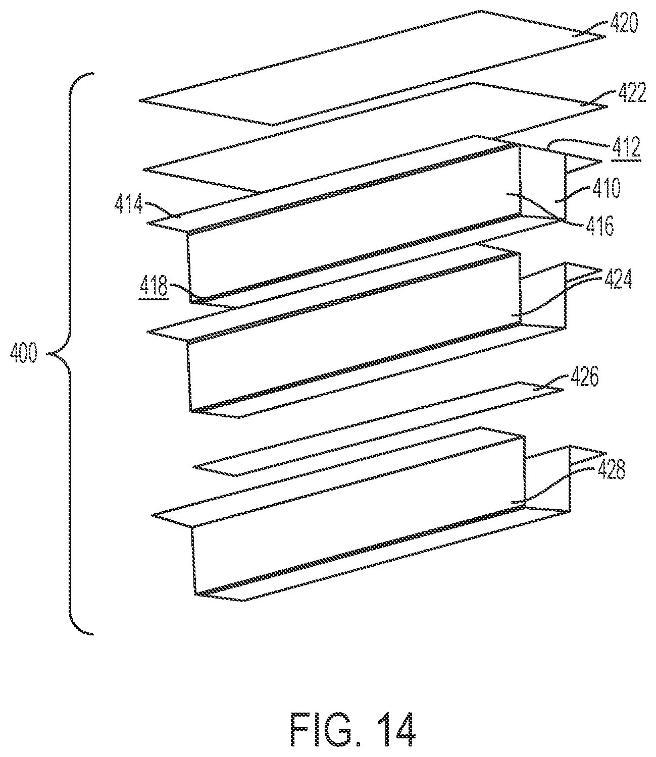
Referring next to FIG. 14, each longitudinal beam 400 may be constructed from a plurality of layers permanently coupled or laminated together. The longitudinal beams 400 may provide stiffness and resistance to bending and deflection in the longitudinal direction and may help couple adjacent transverse beams 300 together. Also, the longitudinal beams 400 may serve as a connection point for another structure, such as a vehicle chassis, a wheel assembly, or a landing gear in trucking applications. From top to bottom in FIG. 14, the illustrative longitudinal beam 400 includes two upper reinforcing layers 420, 422, a preform 410, and three lower reinforcing layers 424, 426, 428, although the number, types, and locations of these layers may vary depending on the needs of the particular application.
The illustrative preform 410 of FIG. 14 has an upper surface 412 with two flanges 414 configured to support the transverse beams 300 located above longitudinal beams 400, side walls 416, and a lower surface 418. From the upper surface 412 to the lower surface 418, the side walls 416 have a slight inward taper or draft such that the preform 410 narrows in width and is generally trapezoidal in cross-section. This trapezoidal shape may facilitate mold extraction, as discussed in Section 7 below. Additional disclosure regarding the preform 410 is set forth in Section 2 above.
As shown in FIG. 14, the upper reinforcing layers 420, 422 are sized and shaped to extend across the upper surface 412 and flanges 414 of the preform 410. Two of the lower reinforcing layers 424, 428 are sized and shaped to wrap around the side walls 416 and the lower surface 418 of the preform 410, whereas the reinforcing layer 426 is a thin strip that is sized and shaped for selective receipt beneath the lower surface 418 of the preform 410. To accommodate different loads on the longitudinal beams 400, each reinforcing layer 420, 422, 424, 426, 428 may be unique to provide a combination of different fiber types, sizes, and/or orientations across the longitudinal beam 400. Additional disclosure regarding the reinforcing layers 420, 422, 424, 426, 428 is set forth in Section 2 above.
In other embodiments, the longitudinal beam 400 may be a non-composite structure, such as a metal (e.g., aluminum) beam or wood beam, for example. In these embodiments, the longitudinal beam 400 may be coupled to the rest of the composite floor structure 100 using structural adhesive and/or mechanical fasteners (e.g., bolts, rivets), for example.
6. Underlayment
Referring back to FIG. 5, underlayment 600 is located below transverse beams 300 and above longitudinal beams 400 in a sandwiched arrangement. Underlayment 600 is arranged parallel to platform 200. Underlayment 600 may be constructed from a plurality of reinforcing layers permanently coupled or laminated together. From top to bottom in FIG. 5, the illustrative underlayment 600 includes three reinforcing layers 620, 622, 624, although the number, types, and locations of these layers may vary depending on the needs of the particular application. When the illustrative composite floor structure 100 is assembled, the top reinforcing layer 620 is coupled to transverse beams 300, and the bottom reinforcing layers 622, 624 are coupled to longitudinal beams 400. It is also within the scope of the present disclosure for underlayment 600 to include a single reinforcing layer (e.g., reinforcing layer 620). In this embodiment, the top surface of the reinforcing layer 620 would be coupled to transverse beams 300, and the bottom surface of reinforcing layer 620 would be coupled to longitudinal beams 400.
Underlayment 600 may experience high tensile stresses, such as when a fork truck drives over the composite floor structure 100. Underlayment 600 may be designed to accommodate the type of floor structure 100, its load rating, the allowed floor maximum deflection requirement, and other requirements. In embodiments where underlayment 600 contains a plurality of reinforcing layer 620, 622, 624, each reinforcing layer 620, 622, 624 may be unique to provide a combination of different fiber types, sizes, and/or orientations across the underlayment 600.
In one example, underlayment 600 includes two reinforcing layers 620 and 622, where reinforcing layer 620 is constructed of a random-orientation chopped fiber fabric, specifically CSM, and reinforcing layer 622 is constructed of a 0/90 fiberglass fabric, specifically E-LTM 3610. The CSM of reinforcing layer 620 may have a weight as low as about 1.5 ounce/yard.sup.2 and as high as about 6.0 ounce/yard.sup.2. The 0/90 fiberglass fabric may have the 90.degree. direction of the fabric being oriented in the lateral direction of the composite floor structure 100 (i.e., perpendicular to the longitudinal axis A of FIG. 4) for added strength in the lateral direction, specifically to help with bending in the transverse direction, and the 0.degree. direction of the fabric being oriented in the longitudinal direction of the composite floor structure 100 (i.e., parallel with the longitudinal axis A of FIG. 4) for added strength in the longitudinal direction, specifically to help tie the caps of the transverse beams together to prevent them from trying to separate when longitudinal bending takes place.
In another example, underlayment 600 includes a single reinforcing layer 620 constructed of a random-orientation chopped fiber fabric, specifically CSM. The CSM of reinforcing layer 620 may have a weight as low as about 1.5 ounce/yard.sup.2 and as high as about 6.0 ounce/yard.sup.2.
In yet another example, underlayment 600 includes a single reinforcing layer 620 constructed of a continuous fiber fabric, specifically a 0/90 fiberglass fabric. The 90.degree. direction of the fabric may be oriented in the lateral direction of the composite floor structure 100 (i.e., perpendicular to the longitudinal axis A of FIG. 4) to help with bending in the transverse direction, and the 0.degree. direction of the fabric being oriented in the longitudinal direction of the composite floor structure 100 (i.e., parallel with the longitudinal axis A of FIG. 4) to help tie the caps of the transverse beams together to prevent them from trying to separate when longitudinal bending takes place.
Additional disclosure regarding the one or more reinforcing layers 620, 622, 624 of underlayment 600 is set forth in Section 2 above.
7. Molding Process
The composite floor structure 100 may be formed by a molding process. An exemplary molding process involves placing the preforms (e.g., preforms 305, 410, 510) and the reinforcing layers (e.g., reinforcing layers 220, 222, 224, 226, 310, 328, 330, 332, 420, 422, 424, 426, 428, 620, 622, 624) together in a mold, wetting the materials with at least one resin and a catalyst to impregnate and/or coat the materials, and curing the materials to form a single, integral, laminated composite floor structure 100. In certain embodiments, the top layer 210 of the platform 200 may also be placed inside the mold and integrally molded with the composite floor structure 100, as discussed in Section 3 above. After curing, the preforms 305, 410, 510 may be extracted from the mold, which may be an open mold or a closed mold.
The resin used to construct the composite floor structure 100 may be a typical resin, a co-cure resin containing a plurality of individual co-curing resins which may be selectively distributed throughout the composite floor structure 100 during the molding process, or a combination thereof. Such co-cure resins may comprise one or more elastomer components, such as urethane, co-cured with one or more resin components, such as a vinyl ester, epoxy, or unsaturated polyester components. Exemplary co-cure resins are disclosed in U.S. Pat. No. 9,371,468 and U.S. Publication No. 2016/0263873, the disclosures of which are hereby incorporated by reference in their entirety. As used herein, "co-cured" refers to the reactions involved in curing the elastomer components take place essentially concurrently with the reactions involved in curing the one or more resin components. In certain embodiments, areas of the composite floor structure 100 that will be susceptible to high stress may receive a resin with a relatively higher polyurethane content for strength, whereas other areas of the composite floor structure 100 that provide bulk and section modulus may receive a lower cost rigid, polyester-based resin, such as an isophthalic polyester resin.
When composite floor structure 100 is part of a cargo vehicle, for example, a similar method may be performed using similar materials to construct other elements of the cargo vehicle, such as the nose, sidewalls, and/or roof.
Additional information regarding the construction of the composite floor structure 100 is disclosed in the following patents and published patent applications, each of which is incorporated by reference in its entirety herein: U.S. Pat. Nos. 5,429,066, 5,800,749, 5,664,518, 5,897,818, 6,013,213, 6,004,492, 5,908,591, 6,497,190, 6,911,252, 5,830,308, 6,755,998, 6,496,190, 6,911,252, 6,723,273, 6,869,561, 8,474,871, 6,206,669, 6,543,469, and 9,371,468, and U.S. Patent Application Publication No. 2014/0262011.
In another embodiment, individual pieces of the composite floor structure 100 may be molded and then coupled together using structural adhesive and/or mechanical fasteners (e.g., bolts, rivets), for example.
While this invention has been described as having an exemplary design, the present invention may be further modified within the spirit and scope of this disclosure. This application is therefore intended to cover any variations, uses, or adaptations of the invention using its general principles. Further, this application is intended to cover such departures from the present disclosure as come within known or customary practices in the art to which this invention pertains.
* * * * *
D00000
D00001
D00002
D00003
D00004
D00005
D00006
D00007
D00008
D00009
D00010
D00011
D00012
D00013
D00014
XML
uspto.report is an independent third-party trademark research tool that is not affiliated, endorsed, or sponsored by the United States Patent and Trademark Office (USPTO) or any other governmental organization. The information provided by uspto.report is based on publicly available data at the time of writing and is intended for informational purposes only.
While we strive to provide accurate and up-to-date information, we do not guarantee the accuracy, completeness, reliability, or suitability of the information displayed on this site. The use of this site is at your own risk. Any reliance you place on such information is therefore strictly at your own risk.
All official trademark data, including owner information, should be verified by visiting the official USPTO website at www.uspto.gov. This site is not intended to replace professional legal advice and should not be used as a substitute for consulting with a legal professional who is knowledgeable about trademark law.