Electric device and motor driving device
Horikoshi , et al. November 3, 2
U.S. patent number 10,827,638 [Application Number 16/245,759] was granted by the patent office on 2020-11-03 for electric device and motor driving device. This patent grant is currently assigned to FANUC CORPORATION. The grantee listed for this patent is FANUC CORPORATION. Invention is credited to Shinichi Horikoshi, Yuuya Nakagawa.


| United States Patent | 10,827,638 |
| Horikoshi , et al. | November 3, 2020 |
Electric device and motor driving device
Abstract
A motor driving device includes a printed board on which a pattern is printed, and a resin board which is formed by molding a resin and on which no pattern is printed, and the printed board is provided on the resin board.
| Inventors: | Horikoshi; Shinichi (Yamanashi-ken, JP), Nakagawa; Yuuya (Yamanashi-ken, JP) | ||||||||||
|---|---|---|---|---|---|---|---|---|---|---|---|
| Applicant: |
|
||||||||||
| Assignee: | FANUC CORPORATION (Yamanashi,
JP) |
||||||||||
| Family ID: | 1000005160272 | ||||||||||
| Appl. No.: | 16/245,759 | ||||||||||
| Filed: | January 11, 2019 |
Prior Publication Data
| Document Identifier | Publication Date | |
|---|---|---|
| US 20190230809 A1 | Jul 25, 2019 | |
Foreign Application Priority Data
| Jan 19, 2018 [JP] | 2018-006951 | |||
| Current U.S. Class: | 1/1 |
| Current CPC Class: | H05K 3/36 (20130101); H05K 1/18 (20130101); H05K 7/1427 (20130101); H05K 1/14 (20130101); H05K 1/0263 (20130101); H05K 7/1432 (20130101); H05K 2201/09818 (20130101) |
| Current International Class: | H05K 7/00 (20060101); H05K 7/14 (20060101); H05K 1/02 (20060101); H05K 3/36 (20060101); H05K 1/18 (20060101); H05K 1/14 (20060101) |
References Cited [Referenced By]
U.S. Patent Documents
| 4853828 | August 1989 | Penn |
| 7207187 | April 2007 | Funahashi |
| 2005/0112956 | May 2005 | Tsugane et al. |
| 2005/0185387 | August 2005 | Suzuki et al. |
| 2009/0122505 | May 2009 | Lu |
| 2013/0033842 | February 2013 | Hara |
| 2017/0042053 | February 2017 | Soyano |
| 1761377 | Apr 2006 | CN | |||
| 102991569 | Mar 2013 | CN | |||
| 107431418 | Dec 2017 | CN | |||
| S60181090 | Dec 1985 | JP | |||
| S6324808 | Oct 1988 | JP | |||
| H02129763 | Oct 1990 | JP | |||
| 2129763 | Nov 1990 | JP | |||
| H03126093 | Dec 1991 | JP | |||
| H07241786 | Sep 1995 | JP | |||
| 2004-147416 | May 2004 | JP | |||
| 2004336945 | Nov 2004 | JP | |||
| 2005-243742 | Sep 2005 | JP | |||
| 2006-286768 | Oct 2006 | JP | |||
Other References
|
Japanese Office Action issued by the Japanese Patent Office in relation to Japanese Application No. 2018-006951 dated Sep. 17, 2019 (3 pages) along with English language machine translation (4 pages). cited by applicant. |
Primary Examiner: Semenenko; Yuriy
Attorney, Agent or Firm: Michal, Esq.; Robert P. Carter, DeLuca & Farrell LLP
Claims
What is claimed is:
1. An electric device comprising: a printed board on which a pattern is printed; a resin board which is formed by molding a resin and on which no pattern is printed; and a short bar through which a current larger than a current passed through the pattern of the printed board is passed, wherein the printed board is provided on the resin board, and the short bar is provided outside a region on the resin board, the region being where the printed board is mounted, wherein the short bar is disposed outside of an outer periphery of the printed board.
2. The electric device according to claim 1, wherein the resin board includes a first positioning portion configured to position the printed board.
3. The electric device according to claim 1, wherein the resin board includes a second positioning portion configured to position the short bar.
4. A motor driving device for supplying electric power to a motor, the motor driving device being the electric device according to claim 1, wherein a control unit configured to control electric power supplied to the motor is mounted on the printed board.
5. The electric device according to claim 1, wherein the short bar has a lower surface, and an opposite upper surface facing away from the resin board, the lower and upper surfaces of the short bar being out of overlapping alignment with the printed board.
6. The electric device according to claim 1, wherein the printed board is a plurality of printed boards mounted on the resin board.
7. The electric device according to claim 1, wherein the printed board has a smaller area than the resin board.
Description
CROSS-REFERENCE TO RELATED APPLICATION
This application is based upon and claims the benefit of priority from Japanese Patent Application No. 2018-006951 filed on Jan. 19, 2018, the contents of which are incorporated herein by reference.
BACKGROUND OF THE INVENTION
Field of the Invention
The present invention relates to an electric device and a motor driving device having a printed board on which a pattern is printed.
Description of the Related Art
Japanese Laid-Open Patent Publication No. 2005-243742 discloses a motor driving device in which short bars are mounted on a printed board.
SUMMARY OF THE INVENTION
According to the technique described in Japanese Laid-Open Patent Publication No. 2005-243742, it is necessary to ensure an area for the provision of the short bars on the printed board, and thus enlarging the area of the printed board, whose unit price per area is high, may increase manufacturing costs of the motor driving device.
The present invention has been made to solve the problem above, and an object of the present invention is to provide an electric device and a motor driving device capable of suppressing manufacturing costs.
According to a first aspect of the present invention, an electric device includes a printed board on which a pattern is printed; and a resin board which is formed by molding a resin and on which no pattern is printed, and the printed board is provided on the resin board.
According to the present invention, it is possible to reduce the area of the printed board with a high unit price, so as to suppress manufacturing costs.
The above and other objects, features, and advantages of the present invention will become more apparent from the following description when taken in conjunction with the accompanying drawings, in which a preferred embodiment of the present invention is shown by way of illustrative example.
BRIEF DESCRIPTION OF THE DRAWINGS
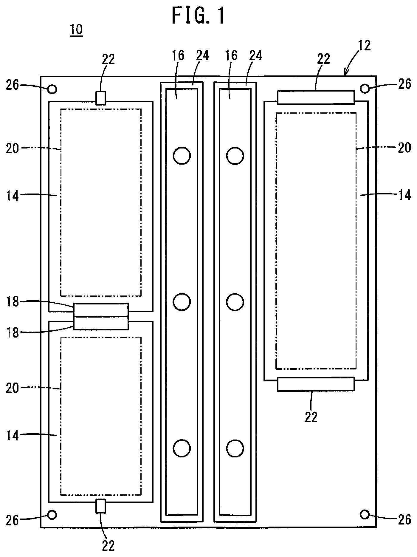
FIG. 1 is a schematic diagram showing the internal structure of a motor driving device; and
FIG. 2 is a schematic diagram showing the internal structure of a conventional motor driving device.
DESCRIPTION OF THE PREFERRED EMBODIMENTS
First Embodiment
[Configuration of Motor Driving Device]
FIG. 1 is a schematic diagram showing the internal structure of a motor driving device 10. The motor driving device 10 is a device which controls electric power supplied to a motor not shown. The motor driving device 10 includes a resin board 12, printed boards 14 provided on the resin board 12, and short bars 16 also provided on the resin board 12.
The resin board 12 is a plate-shaped member produced by injection molding of a resin material. The printed boards 14 are plate-shaped members produced by printing a pattern on a stack of laminated plates formed of resin.
Mounted on the printed boards 14 are control units 20 composed of a plurality of electronic elements and configured to control power supplied to the motor, connectors 18 for making electrical connections with other printed boards 14, and so on. The short bars 16 are connected to a power device (not shown), and a current larger than a current passed through the control units 20 is passed through the short bars 16. The resin board 12 is provided with wiring for connecting the printed boards 14 and the power device, and the like, but no pattern is printed on the resin board 12.
The resin board 12 has first positioning portions 22 for positioning the printed boards 14. The first positioning portions 22 are formed by snap-fit, for example, and the first positioning portions 22 fix the printed boards 14 to the resin board 12.
The resin board 12 has second positioning portions 24 for positioning the short bars 16. The second positioning portions 24 are formed in a groove-like manner along the shape of the short bars 16. The short bars 16 are coupled to the power device by bolts not shown.
The resin board 12 has formed therein a plurality of screw insertion holes 26 in which screws for fixing the resin board 12 to a housing (not shown) are inserted. In the production of the motor driving device 10, first, the printed boards 14 and the short bars 16 are mounted on the resin board 12. Then, the resin board 12 is moved into the housing, and the resin board 12 is fixed to the housing with screws.
[Functions and Effects]
FIG. 2 is a schematic diagram showing the internal structure of a conventional motor driving device 10. Conventionally, short bars 16 are provided on a printed board 14, and the printed board 14 is fixed to a housing by screws. Accordingly, it is necessary to secure on the printed board 14 an area for the provision of the short bars 16, in addition to areas for the provision of control units 20. Furthermore, improving the work efficiency of screwing of the printed board 14 to the housing requires reducing the number of printed boards 14, and it may be necessary in some cases that the printed board 14 have an area larger than an area of the regions in which the control units 20 are actually provided. However, the unit price per area of the printed board 14 is high, and manufacturing costs of the motor driving device 10 will be increased.
Accordingly, in this embodiment, the printed boards 14 and the short bars 16 are mounted on the resin board 12 formed by injection molding. Thus, it is only necessary to secure areas for provision of the control units 20 on the printed boards 14, which makes it possible to reduce the area of the printed boards 14 and thereby suppress manufacturing costs of the motor driving device 10. The resin board 12 can be fixed to the housing with the printed boards 14 and the short bars 16 mounted on the resin board 12, and therefore efficiency in assembling the motor driving device 10 is also ensured.
Furthermore, the resin board 12 includes the first positioning portions 22 for positioning the printed boards 14 and the second positioning portions 24 for positioning the short bars 16. Owing to this, it is possible to further facilitate mounting of the printed boards 14 and the short bars 16 on the resin board 12.
The present embodiment has described the motor driving device 10, but a configuration in which a printed board 14 is provided on a resin board 12 can be applied also to devices for supplying electric power to other equipment, so as to reduce the area of the printed board 14 and suppress manufacturing costs.
Technical Ideas Obtained by Present Embodiment
Technical ideas obtained by the above-described embodiment will be described below.
The electric device (10) includes a printed board (14) on which a pattern is printed; and a resin board (12) which is formed by molding a resin and on which no pattern is printed, and the printed board (14) is provided on the resin board (12). This makes it possible to reduce the area of the printed board (14) and thereby suppress manufacturing costs of the electric device (10).
In the electric device (10) above, the resin board (12) may include a first positioning portion (22) configured to position the printed board (14). This can further facilitate mounting of the printed board (14) on the resin board (12).
The electric device (10) above may further include a short bar (16) through which a current larger than a current passed through the pattern of the printed board (14) is passed, and the short bar (16) may be provided on the resin board (12). This makes it possible to reduce the area of the printed board (14) and thereby suppress manufacturing costs of the electric device (10).
In the electric device (10) above, the resin board (12) may include a second positioning portion (24) configured to position the short bar (16). This improves facility of mounting of the short bar (16) on the resin board (12).
The electric device (10) described above may be a motor driving device (10) for supplying electric power to a motor, and a control unit (20) configured to control the electric power supplied to the motor may be mounted on the printed board (14). This makes it possible to reduce the area of the printed board (14) and thereby suppress manufacturing costs of the motor driving device (10).
The present invention is not particularly limited to the embodiments described above, and various modifications are possible without departing from the essence and gist of the present invention.
* * * * *
D00000
D00001
D00002
XML
uspto.report is an independent third-party trademark research tool that is not affiliated, endorsed, or sponsored by the United States Patent and Trademark Office (USPTO) or any other governmental organization. The information provided by uspto.report is based on publicly available data at the time of writing and is intended for informational purposes only.
While we strive to provide accurate and up-to-date information, we do not guarantee the accuracy, completeness, reliability, or suitability of the information displayed on this site. The use of this site is at your own risk. Any reliance you place on such information is therefore strictly at your own risk.
All official trademark data, including owner information, should be verified by visiting the official USPTO website at www.uspto.gov. This site is not intended to replace professional legal advice and should not be used as a substitute for consulting with a legal professional who is knowledgeable about trademark law.