Magnetic field sensor having unequally spaced magnetic field sensing elements
Eagen , et al. November 3, 2
U.S. patent number 10,823,586 [Application Number 16/232,348] was granted by the patent office on 2020-11-03 for magnetic field sensor having unequally spaced magnetic field sensing elements. This patent grant is currently assigned to Allegro MicroSystems, LLC. The grantee listed for this patent is Allegro MicroSystems, LLC. Invention is credited to Paul A. David, Jeffrey Eagen.


View All Diagrams
| United States Patent | 10,823,586 |
| Eagen , et al. | November 3, 2020 |
Magnetic field sensor having unequally spaced magnetic field sensing elements
Abstract
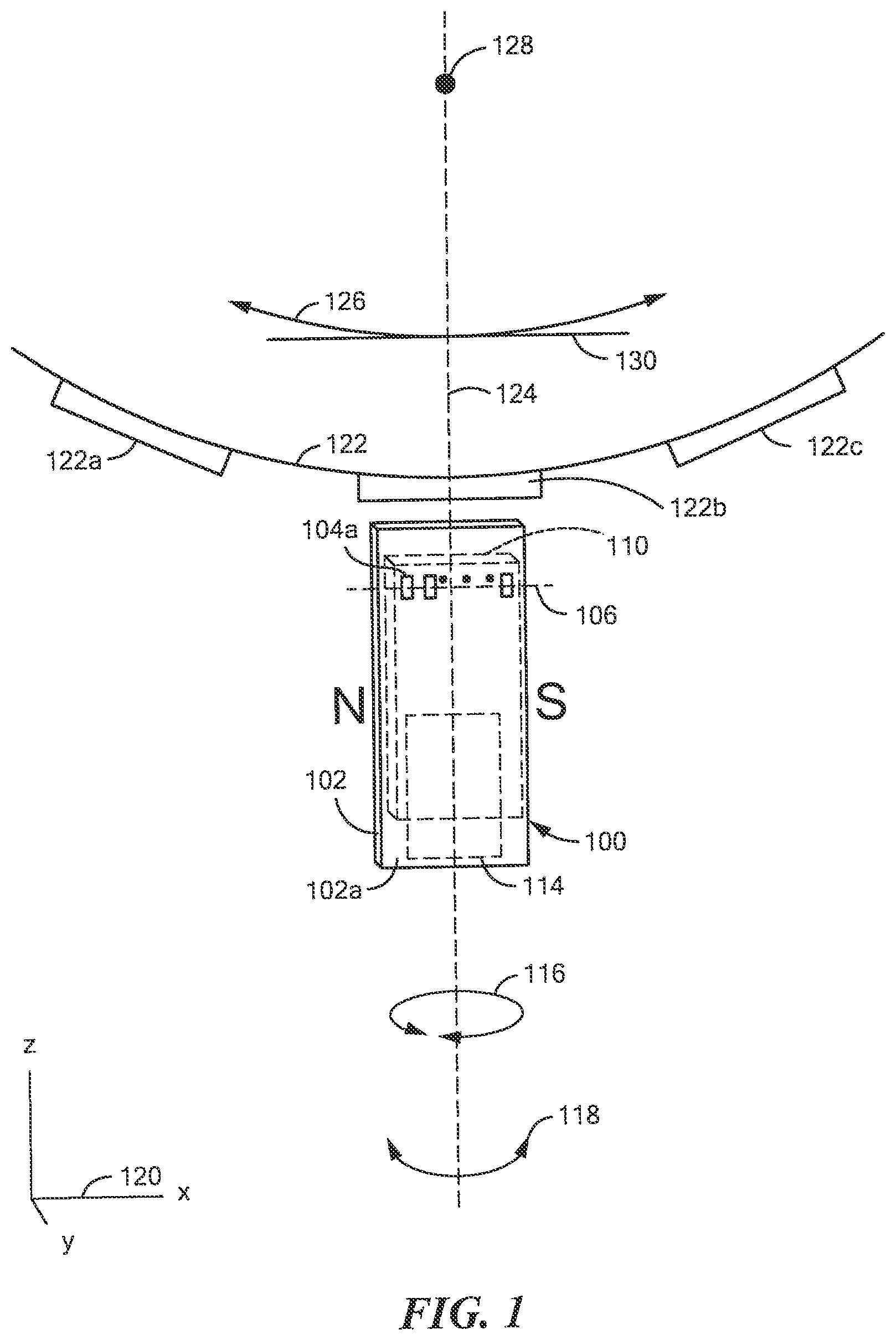
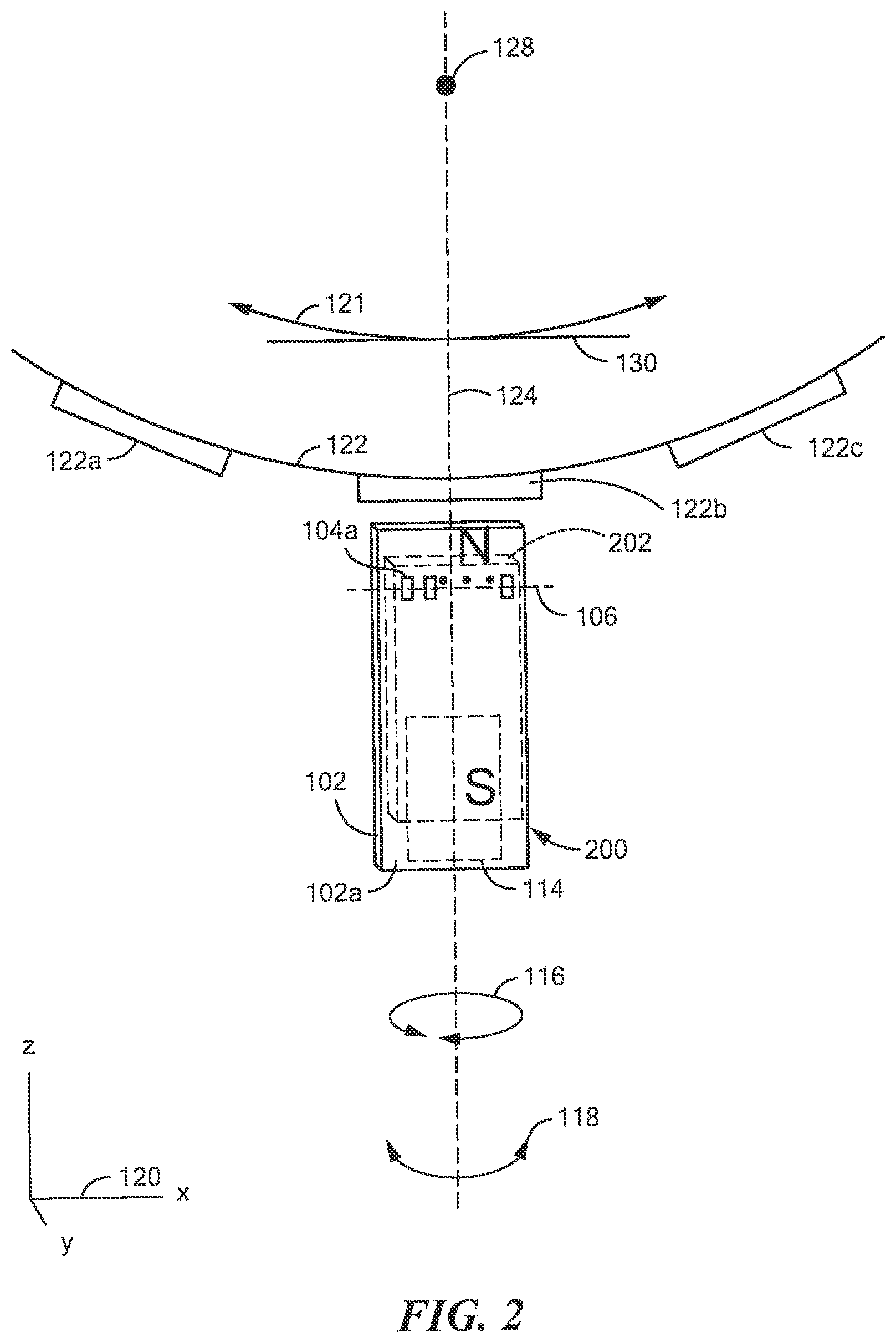
A magnetic field sensor for sensing a movement of a target object an include a substrate having a major planar surface and three or more magnetic field sensing elements disposed upon the major planar surface of the substrate. The three or more magnetic field sensing elements can have respective major response axes, each major response axis parallel to the major planar surface of the substrate. The three or more magnetic field sensing elements comprise first and third magnetic field sensing elements and a second magnetic field sensing element disposed between the first and third magnetic field sensing elements. A first spacing between the first and second magnetic field sensing elements is less than a second spacing between the second and third magnetic field sensing elements. No other magnetic field sensing elements are disposed between the first and third magnetoresistance elements.
| Inventors: | Eagen; Jeffrey (Manchester, NH), David; Paul A. (Bow, NH) | ||||||||||
|---|---|---|---|---|---|---|---|---|---|---|---|
| Applicant: |
|
||||||||||
| Assignee: | Allegro MicroSystems, LLC
(Manchester, NH) |
||||||||||
| Family ID: | 1000005156822 | ||||||||||
| Appl. No.: | 16/232,348 | ||||||||||
| Filed: | December 26, 2018 |
Prior Publication Data
| Document Identifier | Publication Date | |
|---|---|---|
| US 20200209017 A1 | Jul 2, 2020 | |
| Current U.S. Class: | 1/1 |
| Current CPC Class: | G01M 13/021 (20130101); G01D 5/145 (20130101); G01D 5/245 (20130101) |
| Current International Class: | G01D 5/245 (20060101); G01M 13/021 (20190101); G01D 5/14 (20060101) |
| Field of Search: | ;324/206,207.2,242,258,252,260 |
References Cited [Referenced By]
U.S. Patent Documents
| 3132337 | May 1964 | Martin |
| 3195043 | July 1965 | Burig et al. |
| 3281628 | October 1966 | Bauer et al. |
| 3607528 | September 1971 | Gassaway |
| 3611138 | October 1971 | Winebrener |
| 3661061 | May 1972 | Tokarz |
| 3728786 | April 1973 | Lucas et al. |
| 4048670 | September 1977 | Eysermans |
| 4079360 | March 1978 | Ookubo et al. |
| 4180753 | December 1979 | Cook, II |
| 4188605 | February 1980 | Stout |
| 4204317 | May 1980 | Winn |
| 4236832 | December 1980 | Komatsu et al. |
| 4283643 | August 1981 | Levin |
| 4315523 | February 1982 | Mahawili et al. |
| 4438347 | March 1984 | Gehring |
| 4490674 | December 1984 | Ito |
| 4573258 | March 1986 | Io et al. |
| 4614111 | September 1986 | Wolff |
| 4649796 | March 1987 | Schmidt |
| 4668914 | May 1987 | Kersten et al. |
| 4670715 | June 1987 | Fuzzell |
| 4719419 | January 1988 | Dawley |
| 4733455 | March 1988 | Nakamura et al. |
| 4745363 | May 1988 | Carr et al. |
| 4746859 | May 1988 | Malik |
| 4752733 | June 1988 | Petr et al. |
| 4758943 | July 1988 | Astrom et al. |
| 4760285 | July 1988 | Nelson |
| 4761569 | August 1988 | Higgs |
| 4764767 | August 1988 | Ichikawa et al. |
| 4769344 | September 1988 | Sakai et al. |
| 4772929 | September 1988 | Manchester |
| 4789826 | December 1988 | Willett |
| 4796354 | January 1989 | Yokoyama et al. |
| 4823075 | April 1989 | Alley |
| 4829352 | May 1989 | Popovic et al. |
| 4833406 | May 1989 | Foster |
| 4893027 | January 1990 | Kammerer et al. |
| 4908685 | March 1990 | Shibasaki et al. |
| 4910861 | March 1990 | Dohogne |
| 4935698 | June 1990 | Kawaji et al. |
| 4944028 | July 1990 | Iijima et al. |
| 4954777 | September 1990 | Klopfer et al. |
| 4970411 | November 1990 | Halg et al. |
| 4983916 | January 1991 | Iijima et al. |
| 5012322 | April 1991 | Guillotte |
| 5021493 | June 1991 | Sandstrom |
| 5028868 | July 1991 | Murata et al. |
| 5038130 | August 1991 | Eck et al. |
| 5045920 | September 1991 | Vig et al. |
| 5078944 | January 1992 | Yoshino |
| 5084289 | January 1992 | Shin et al. |
| 5121289 | June 1992 | Gagliardi |
| 5137677 | August 1992 | Murata |
| 5139973 | August 1992 | Nagy et al. |
| 5167896 | December 1992 | Hirota et al. |
| 5168244 | December 1992 | Muranaka |
| 5185919 | February 1993 | Hickey |
| 5196794 | March 1993 | Murata |
| 5200698 | April 1993 | Thibaud |
| 5210493 | May 1993 | Schroeder et al. |
| 5216405 | June 1993 | Schroeder et al. |
| 5220207 | June 1993 | Kovalcik et al. |
| 5244834 | September 1993 | Suzuki et al. |
| 5247202 | September 1993 | Popovic et al. |
| 5247278 | September 1993 | Pant et al. |
| 5250925 | October 1993 | Shinkle |
| 5286426 | February 1994 | Rano, Jr. et al. |
| 5289344 | February 1994 | Gagnon et al. |
| 5291133 | March 1994 | Gokhale et al. |
| 5304926 | April 1994 | Wu |
| 5315245 | May 1994 | Schroeder et al. |
| 5329416 | July 1994 | Ushiyama et al. |
| 5331478 | July 1994 | Aranovsky |
| 5332956 | July 1994 | Oh |
| 5332965 | July 1994 | Wolf et al. |
| 5341097 | August 1994 | Wu |
| 5351028 | September 1994 | Krahn |
| 5399968 | March 1995 | Sheppard et al. |
| 5412255 | May 1995 | Wallrafen |
| 5414355 | May 1995 | Davidson et al. |
| 5424558 | June 1995 | Borden et al. |
| 5432444 | July 1995 | Yasohama et al. |
| 5434105 | July 1995 | Liou |
| 5453727 | September 1995 | Shibasaki et al. |
| 5469058 | November 1995 | Dunnam |
| 5477143 | December 1995 | Wu |
| 5479695 | January 1996 | Grader et al. |
| 5486759 | January 1996 | Seiler et al. |
| 5488294 | January 1996 | Liddell et al. |
| 5491633 | February 1996 | Henry et al. |
| 5497081 | March 1996 | Wolf et al. |
| 5497083 | March 1996 | Nakazato et al. |
| 5500589 | March 1996 | Sumcad |
| 5500994 | March 1996 | Itaya |
| 5508611 | April 1996 | Schroeder et al. |
| 5521501 | May 1996 | Dettmann et al. |
| 5541506 | July 1996 | Kawakita et al. |
| 5545983 | August 1996 | Okeya et al. |
| 5551146 | September 1996 | Kawabata et al. |
| 5552706 | September 1996 | Carr |
| 5572058 | November 1996 | Biard |
| 5581170 | December 1996 | Mammano et al. |
| 5581179 | December 1996 | Engel et al. |
| 5583436 | December 1996 | Van De Walle et al. |
| 5585574 | December 1996 | Sugihara et al. |
| 5596272 | January 1997 | Busch |
| 5612618 | March 1997 | Arakawa |
| 5619137 | April 1997 | Vig et al. |
| 5621319 | April 1997 | Bilotti et al. |
| 5627315 | May 1997 | Figi et al. |
| 5631557 | May 1997 | Davidson |
| 5640090 | June 1997 | Furuya et al. |
| 5657189 | August 1997 | Sandhu |
| 5691637 | November 1997 | Oswald et al. |
| 5694038 | December 1997 | Moody et al. |
| 5696790 | December 1997 | Graham et al. |
| 5712562 | January 1998 | Berg |
| 5714102 | February 1998 | Highum et al. |
| 5719496 | February 1998 | Wolf |
| 5729128 | March 1998 | Bunyer et al. |
| 5757181 | May 1998 | Wolf et al. |
| 5781005 | July 1998 | Vig et al. |
| 5789658 | August 1998 | Henn et al. |
| 5789915 | August 1998 | Ingraham |
| 5796249 | August 1998 | Andraet et al. |
| 5818222 | October 1998 | Ramsden |
| 5818223 | October 1998 | Wolf |
| 5831513 | November 1998 | Lue |
| 5839185 | November 1998 | Smith et al. |
| 5841276 | November 1998 | Makino et al. |
| 5844411 | December 1998 | Vogt |
| 5859387 | January 1999 | Gagnon |
| 5886070 | February 1999 | Honkura et al. |
| 5883567 | March 1999 | Mullins, Jr. |
| 5912556 | June 1999 | Frazee et al. |
| 5942895 | August 1999 | Popovic et al. |
| 5963028 | October 1999 | Engel et al. |
| 6011770 | January 2000 | Tan |
| 6016055 | January 2000 | Jager et al. |
| 6043644 | March 2000 | de Coulon et al. |
| 6043646 | March 2000 | Jansseune |
| 6064199 | May 2000 | Walter et al. |
| 6064202 | May 2000 | Steiner et al. |
| 6091239 | July 2000 | Vig et al. |
| 6100680 | August 2000 | Vig et al. |
| 6100754 | August 2000 | Kim et al. |
| 6136250 | October 2000 | Brown |
| 6166535 | December 2000 | Irle et al. |
| 6169396 | January 2001 | Yokotani et al. |
| 6175232 | January 2001 | De Coulon et al. |
| 6175233 | January 2001 | McCurley et al. |
| 6180041 | January 2001 | Takizawa |
| 6181036 | January 2001 | Kazama et al. |
| 6184679 | February 2001 | Popovic et al. |
| 6194893 | February 2001 | Yokotani et al. |
| 6198373 | March 2001 | Ogawa et al. |
| 6232768 | May 2001 | Moody et al. |
| 6236199 | May 2001 | Irle et al. |
| 6242604 | June 2001 | Hudlicky et al. |
| 6242904 | June 2001 | Shirai et al. |
| 6242905 | June 2001 | Draxelmayr |
| 6265864 | July 2001 | De Winter et al. |
| 6265865 | July 2001 | Engel et al. |
| 6278269 | August 2001 | Vig et al. |
| 6288533 | September 2001 | Haeberli et al. |
| 6291989 | September 2001 | Schroeder |
| 6297627 | October 2001 | Towne et al. |
| 6297628 | October 2001 | Bicking et al. |
| 6323642 | November 2001 | Nishimura et al. |
| 6339322 | January 2002 | Loreck et al. |
| 6351506 | February 2002 | Lewicki |
| 6356068 | March 2002 | Steiner et al. |
| 6356741 | March 2002 | Bilotti et al. |
| 6366079 | April 2002 | Uenoyama |
| 6392478 | May 2002 | Mulder et al. |
| 6429640 | August 2002 | Daughton et al. |
| 6436748 | August 2002 | Forbes et al. |
| 6437558 | August 2002 | Li et al. |
| 6452381 | September 2002 | Nakatani et al. |
| 6462536 | October 2002 | Mednikov et al. |
| 6492804 | December 2002 | Tsuge et al. |
| 6501270 | December 2002 | Opie |
| 6504363 | January 2003 | Dogaru et al. |
| 6525531 | February 2003 | Forrest et al. |
| 6528992 | March 2003 | Shinjo et al. |
| 6542068 | April 2003 | Drapp et al. |
| 6542847 | April 2003 | Lohberg et al. |
| 6545332 | April 2003 | Huang |
| 6545457 | April 2003 | Goto et al. |
| 6545462 | April 2003 | Schott et al. |
| 6566862 | May 2003 | Goto et al. |
| 6566872 | May 2003 | Sugitani |
| 6590804 | July 2003 | Perner |
| 6622012 | September 2003 | Bilotti et al. |
| 6640451 | November 2003 | Vinarcik |
| 6653968 | November 2003 | Schneider |
| 6674679 | January 2004 | Perner et al. |
| 6687644 | February 2004 | Zinke et al. |
| 6692676 | February 2004 | Vig et al. |
| 6759843 | July 2004 | Furlong |
| 6768301 | July 2004 | Hohe et al. |
| 6770163 | August 2004 | Kuah et al. |
| 6781233 | August 2004 | Zverev et al. |
| 6781359 | August 2004 | Stauth et al. |
| 6798193 | September 2004 | Zimmerman et al. |
| 6815944 | November 2004 | Vig et al. |
| 6822443 | November 2004 | Dogaru |
| 6853178 | February 2005 | Hayat-Dawoodi |
| 6896407 | May 2005 | Nomiyama et al. |
| 6902951 | June 2005 | Goller et al. |
| 6917321 | July 2005 | Haurie et al. |
| 6969988 | November 2005 | Kakuta et al. |
| 7023205 | April 2006 | Krupp |
| 7026808 | April 2006 | Vig et al. |
| 7030606 | April 2006 | Kato et al. |
| 7031170 | April 2006 | Daeche et al. |
| 7038448 | May 2006 | Schott et al. |
| 7049924 | May 2006 | Hayashi et al. |
| 7085119 | August 2006 | Bilotti et al. |
| 7112955 | September 2006 | Buchhold |
| 7112957 | September 2006 | Bicking |
| 7119538 | October 2006 | Blossfeld |
| 7126327 | October 2006 | Busch |
| 7132825 | November 2006 | Martin |
| 7159556 | January 2007 | Yoshihara |
| 7184876 | February 2007 | Tuelings et al. |
| 7190784 | March 2007 | Li |
| 7193412 | March 2007 | Freeman |
| 7199579 | April 2007 | Scheller et al. |
| 7235968 | June 2007 | Popovic et al. |
| 7250760 | July 2007 | Ao |
| 7259545 | August 2007 | Stauth et al. |
| 7259556 | August 2007 | Popovic et al. |
| 7265531 | September 2007 | Stauth et al. |
| 7269992 | September 2007 | Lamb et al. |
| 7285952 | October 2007 | Hatanaka et al. |
| 7292095 | November 2007 | Burt et al. |
| 7295000 | November 2007 | Werth |
| 7307824 | December 2007 | Bilotti et al. |
| 7319319 | January 2008 | Jones et al. |
| 7323780 | January 2008 | Daubenspeck et al. |
| 7323870 | January 2008 | Tatschl et al. |
| 7325175 | January 2008 | Momtaz |
| 7345468 | March 2008 | Okada et al. |
| 7355388 | April 2008 | Ishio |
| 7361531 | April 2008 | Sharma et al. |
| 7362094 | April 2008 | Voisine et al. |
| 7365530 | April 2008 | Bailey et al. |
| 7385394 | June 2008 | Auburger et al. |
| 7425821 | September 2008 | Monreal et al. |
| 7474093 | January 2009 | Ausserlechner |
| 7476953 | January 2009 | Taylor et al. |
| 7518354 | April 2009 | Stauth et al. |
| 7592801 | September 2009 | Bailey et al. |
| 7598601 | October 2009 | Taylor et al. |
| 7605647 | October 2009 | Romero et al. |
| 7635993 | December 2009 | Boeve |
| 7694200 | April 2010 | Forrest et al. |
| 7701208 | April 2010 | Nishikawa |
| 7714570 | May 2010 | Thomas et al. |
| 7729675 | June 2010 | Krone |
| 7746056 | June 2010 | Stauth et al. |
| 7746065 | June 2010 | Pastre et al. |
| 7759929 | July 2010 | Forsyth |
| 7764118 | July 2010 | Kusuda et al. |
| 7768083 | August 2010 | Doogue et al. |
| 7769110 | August 2010 | Momtaz |
| 7772838 | August 2010 | Bailey et al. |
| 7800389 | September 2010 | Friedrich et al. |
| 7808074 | October 2010 | Knittl |
| 7816772 | October 2010 | Engel et al. |
| 7816905 | October 2010 | Doogue et al. |
| 7839141 | November 2010 | Werth et al. |
| 7872322 | January 2011 | Schott et al. |
| 7911203 | March 2011 | Thomas et al. |
| 7915886 | March 2011 | Stolfus et al. |
| 7923996 | April 2011 | Doogue et al. |
| 7936144 | May 2011 | Vig et al. |
| 7956604 | June 2011 | Ausserlechner |
| 7961823 | June 2011 | Kolze et al. |
| 7965076 | June 2011 | Schott |
| 7990209 | August 2011 | Romero |
| 7994774 | August 2011 | Thomas et al. |
| 8030918 | October 2011 | Doogue et al. |
| 8058870 | November 2011 | Sterling |
| 8063631 | November 2011 | Fermon et al. |
| 8063634 | November 2011 | Sauber et al. |
| 8080993 | December 2011 | Theuss et al. |
| 8089276 | January 2012 | Kentsch |
| 8106649 | January 2012 | Kaita et al. |
| 8106654 | January 2012 | Theuss et al. |
| 8128549 | March 2012 | Testani et al. |
| 8134358 | March 2012 | Charlier et al. |
| 8143169 | March 2012 | Engel et al. |
| 8253210 | August 2012 | Theuss et al. |
| 8274279 | September 2012 | Gies |
| 8362579 | January 2013 | Theuss et al. |
| 8542010 | September 2013 | Cesaretti et al. |
| 8559139 | October 2013 | Theuss |
| 8577634 | November 2013 | Donovan et al. |
| 8610430 | December 2013 | Werth et al. |
| 8624588 | January 2014 | Vig et al. |
| 8629539 | January 2014 | Milano et al. |
| 8680846 | March 2014 | Cesaretti et al. |
| 8723512 | May 2014 | Burdette et al. |
| 8754640 | June 2014 | Vig et al. |
| 8773124 | July 2014 | Ausserlechner |
| 8860404 | October 2014 | Dwyer et al. |
| 9081041 | July 2015 | Friedrich et al. |
| 9116018 | August 2015 | Frachon |
| 9164156 | October 2015 | Elian et al. |
| 9201122 | December 2015 | Cesaretti et al. |
| 9201123 | December 2015 | Elian et al. |
| 9347799 | May 2016 | Nazarian et al. |
| 9411025 | August 2016 | David et al. |
| 9719806 | August 2017 | Foletto et al. |
| 9720054 | August 2017 | Drouin et al. |
| 9810519 | November 2017 | Taylor et al. |
| 9823090 | November 2017 | Foletto et al. |
| 9823092 | November 2017 | David et al. |
| 10041810 | August 2018 | Vig et al. |
| 10234513 | March 2019 | Vig et al. |
| 10408892 | September 2019 | David et al. |
| 2001/0002791 | June 2001 | Tsuge et al. |
| 2001/0009367 | July 2001 | Seitzer et al. |
| 2001/0026153 | October 2001 | Nakamura et al. |
| 2002/0027488 | March 2002 | Hayat-Dawoodi et al. |
| 2002/0084923 | July 2002 | Li |
| 2002/0097639 | July 2002 | Ishizaki et al. |
| 2003/0001563 | January 2003 | Turner |
| 2003/0038675 | February 2003 | Gailus et al. |
| 2003/0062891 | April 2003 | Slates |
| 2003/0102909 | June 2003 | Motz |
| 2003/0107366 | June 2003 | Busch et al. |
| 2003/0151406 | August 2003 | Wan et al. |
| 2003/0173955 | September 2003 | Uenoyama |
| 2003/0222642 | December 2003 | Butzmann |
| 2003/0227286 | December 2003 | Dunisch et al. |
| 2004/0032251 | February 2004 | Zimmerman et al. |
| 2004/0046248 | March 2004 | Waelti et al. |
| 2004/0056647 | March 2004 | Stauth et al. |
| 2004/0062362 | April 2004 | Matsuya |
| 2004/0080314 | April 2004 | Tsujii et al. |
| 2004/0135220 | July 2004 | Goto |
| 2004/0170052 | September 2004 | Inui |
| 2004/0174164 | September 2004 | Ao |
| 2004/0184196 | September 2004 | Jayasekara |
| 2004/0189285 | September 2004 | Uenoyama |
| 2004/0196045 | October 2004 | Larsen |
| 2004/0252563 | December 2004 | Hokuto et al. |
| 2004/0263014 | December 2004 | Miya |
| 2005/0017709 | January 2005 | Stolfus et al. |
| 2005/0120782 | June 2005 | Kishibata et al. |
| 2005/0122095 | June 2005 | Dooley |
| 2005/0122099 | June 2005 | Imamoto et al. |
| 2005/0167790 | August 2005 | Khor et al. |
| 2005/0179429 | August 2005 | Lohberg |
| 2005/0225318 | October 2005 | Bailey et al. |
| 2005/0280411 | December 2005 | Bicking |
| 2006/0011999 | January 2006 | Schott et al. |
| 2006/0028204 | February 2006 | Oohira |
| 2006/0033487 | February 2006 | Nagano et al. |
| 2006/0038559 | February 2006 | Lamb et al. |
| 2006/0038561 | February 2006 | Honkura et al. |
| 2006/0068237 | March 2006 | Murphy |
| 2006/0097715 | May 2006 | Oohira et al. |
| 2006/0097717 | May 2006 | Tokuhara et al. |
| 2006/0125473 | June 2006 | Frachon et al. |
| 2006/0175674 | August 2006 | Taylor |
| 2006/0181263 | August 2006 | Doogue et al. |
| 2006/0202692 | September 2006 | Tatschl et al. |
| 2006/0238190 | October 2006 | Ishio |
| 2006/0261801 | November 2006 | Busch |
| 2007/0110199 | May 2007 | Momtaz et al. |
| 2007/0170533 | July 2007 | Doogue et al. |
| 2007/0247141 | October 2007 | Pastre et al. |
| 2007/0285089 | December 2007 | Ibuki et al. |
| 2007/0290682 | December 2007 | Oohira et al. |
| 2008/0012558 | January 2008 | Rossler et al. |
| 2008/0013298 | January 2008 | Sharma et al. |
| 2008/0094055 | April 2008 | Monreal et al. |
| 2008/0116884 | May 2008 | Rettig et al. |
| 2008/0116885 | May 2008 | Van Zon et al. |
| 2008/0137784 | June 2008 | Krone |
| 2008/0237818 | October 2008 | Engel et al. |
| 2008/0238410 | October 2008 | Charlier et al. |
| 2009/0001964 | January 2009 | Strzalkowski |
| 2009/0001965 | January 2009 | Ausserlechner et al. |
| 2009/0001972 | January 2009 | Fernandez et al. |
| 2009/0009163 | January 2009 | Yamada |
| 2009/0058404 | March 2009 | Kurumado |
| 2009/0085706 | April 2009 | Baarman et al. |
| 2009/0102467 | April 2009 | Snell et al. |
| 2009/0121707 | May 2009 | Schott |
| 2009/0137398 | May 2009 | Bozovic et al. |
| 2009/0140725 | June 2009 | Ausserlechner |
| 2009/0146647 | June 2009 | Ausserlechner |
| 2009/0152696 | June 2009 | Dimasacat et al. |
| 2009/0167298 | July 2009 | Kreutzbruck et al. |
| 2009/0167301 | July 2009 | Ausserlechner |
| 2009/0168286 | July 2009 | Berkley et al. |
| 2009/0174395 | July 2009 | Thomas et al. |
| 2009/0189600 | July 2009 | Kurkovskiy |
| 2009/0206827 | August 2009 | Aimuta et al. |
| 2009/0206831 | August 2009 | Fermon et al. |
| 2009/0212765 | August 2009 | Doogue et al. |
| 2009/0243601 | October 2009 | Feldtkeller |
| 2009/0251134 | October 2009 | Uenoyama |
| 2009/0256552 | October 2009 | Guo et al. |
| 2009/0262466 | October 2009 | Kurata et al. |
| 2009/0315543 | December 2009 | Guo et al. |
| 2009/0322325 | December 2009 | Ausserlechner |
| 2009/0326860 | December 2009 | Hainz et al. |
| 2010/0026279 | February 2010 | Vig et al. |
| 2010/0026288 | February 2010 | Sauber et al. |
| 2010/0033175 | February 2010 | Boeve et al. |
| 2010/0045268 | February 2010 | Kilian |
| 2010/0052667 | March 2010 | Kohama et al. |
| 2010/0072988 | March 2010 | Hammerschmidt et al. |
| 2010/0141249 | June 2010 | Ararao et al. |
| 2010/0156397 | June 2010 | Yabusaki et al. |
| 2010/0164491 | July 2010 | Kejik et al. |
| 2010/0188078 | July 2010 | Foletto et al. |
| 2010/0201356 | August 2010 | Koller et al. |
| 2010/0211347 | August 2010 | Friedrich et al. |
| 2010/0237450 | September 2010 | Doogue et al. |
| 2010/0276769 | November 2010 | Theuss et al. |
| 2010/0295140 | November 2010 | Theuss et al. |
| 2010/0330708 | December 2010 | Engel et al. |
| 2011/0004278 | January 2011 | Aghassian et al. |
| 2011/0018533 | January 2011 | Cesaretti et al. |
| 2011/0031960 | February 2011 | Hohe et al. |
| 2011/0048102 | March 2011 | Fernandez et al. |
| 2011/0074405 | March 2011 | Doogue et al. |
| 2011/0127998 | June 2011 | Elian et al. |
| 2011/0175605 | July 2011 | Kim et al. |
| 2011/0224537 | September 2011 | Brunner |
| 2011/0248708 | October 2011 | Thomas et al. |
| 2011/0267040 | November 2011 | Frachon |
| 2011/0285384 | November 2011 | Nomura |
| 2011/0291650 | December 2011 | Franke et al. |
| 2011/0298448 | December 2011 | Foletto et al. |
| 2012/0007589 | January 2012 | Okada |
| 2012/0013333 | January 2012 | Ararao et al. |
| 2012/0019236 | January 2012 | Tiernan et al. |
| 2012/0062215 | March 2012 | Ide et al. |
| 2012/0086090 | April 2012 | Sharma et al. |
| 2012/0200290 | August 2012 | Ausserlechner |
| 2012/0249133 | October 2012 | Friedrich |
| 2012/0274314 | November 2012 | Cesaretti et al. |
| 2012/0293167 | November 2012 | Kitanaka et al. |
| 2012/0303305 | November 2012 | Bergqvist et al. |
| 2013/0015845 | January 2013 | Fox |
| 2013/0057257 | March 2013 | Friedrich et al. |
| 2013/0113474 | May 2013 | Elian |
| 2013/0214774 | August 2013 | Cesaretti et al. |
| 2013/0238278 | September 2013 | Shoemaker et al. |
| 2013/0241543 | September 2013 | Stenson et al. |
| 2013/0249546 | September 2013 | David et al. |
| 2013/0265037 | October 2013 | Friedrich et al. |
| 2013/0278246 | October 2013 | Stegerer et al. |
| 2013/0300401 | November 2013 | Krapf et al. |
| 2013/0320970 | December 2013 | Foletto et al. |
| 2013/0335069 | December 2013 | Vig et al. |
| 2014/0084906 | March 2014 | Ruigrok et al. |
| 2014/0175584 | June 2014 | Foletto et al. |
| 2014/0176126 | June 2014 | Friedrich et al. |
| 2014/0232379 | August 2014 | Nazarian et al. |
| 2014/0266176 | September 2014 | Fernandez et al. |
| 2014/0266181 | September 2014 | Milano et al. |
| 2014/0305761 | October 2014 | Kimes |
| 2014/0327435 | November 2014 | Rohrer |
| 2014/0347044 | November 2014 | Monreal et al. |
| 2015/0022186 | January 2015 | Ausserlechner |
| 2015/0022187 | January 2015 | Taylor et al. |
| 2015/0022193 | January 2015 | Burdette et al. |
| 2015/0022197 | January 2015 | David et al. |
| 2015/0022198 | January 2015 | David et al. |
| 2015/0211895 | July 2015 | Reitsma et al. |
| 2015/0346289 | December 2015 | Ausserlechner |
| 2015/0377648 | December 2015 | Sirohiwala et al. |
| 2016/0025820 | January 2016 | Scheller et al. |
| 2016/0069662 | March 2016 | Mullenix et al. |
| 2016/0123774 | May 2016 | Foletto et al. |
| 2017/0271399 | September 2017 | Lee et al. |
| 2017/0285117 | October 2017 | Drouin et al. |
| 2017/0307696 | October 2017 | Werth et al. |
| 2017/0314907 | November 2017 | Taylor et al. |
| 2017/0328739 | November 2017 | David et al. |
| 2017/0356760 | December 2017 | David et al. |
| 2018/0011150 | January 2018 | Pepka et al. |
| 2018/0340911 | November 2018 | Romero et al. |
| 2018/0340986 | November 2018 | Latham et al. |
| 2018/0340988 | November 2018 | Latham et al. |
| 2018/0340989 | November 2018 | Latham et al. |
| 2019/0033096 | January 2019 | David et al. |
| 2019/0162784 | May 2019 | Lassalle-Balier |
| 683469 | Mar 1994 | CH | |||
| 102323554 | Jan 2012 | CN | |||
| 102483443 | May 2012 | CN | |||
| 102713654 | Oct 2012 | CN | |||
| 102954808 | Mar 2013 | CN | |||
| 2518054 | Nov 1976 | DE | |||
| 4031560 | Apr 1992 | DE | |||
| 19539458 | Apr 1997 | DE | |||
| 68927973 | Sep 1997 | DE | |||
| 19634715 | Mar 1998 | DE | |||
| 19650935 | Jun 1998 | DE | |||
| 19838433 | Mar 1999 | DE | |||
| 19851839 | Nov 1999 | DE | |||
| 19961504 | Jun 2001 | DE | |||
| 10210184 | Sep 2003 | DE | |||
| 10314602 | Oct 2004 | DE | |||
| 102005014509 | Oct 2006 | DE | |||
| 102006037226 | Feb 2008 | DE | |||
| 102007018238 | Oct 2008 | DE | |||
| 102007041230 | Apr 2009 | DE | |||
| 102010016584 | Nov 2010 | DE | |||
| 102011102483 | Nov 2012 | DE | |||
| 0146091 | Jun 1985 | EP | |||
| 0289414 | Feb 1988 | EP | |||
| 0289414 | Feb 1988 | EP | |||
| 0357013 | Mar 1990 | EP | |||
| 0357013 | Mar 1990 | EP | |||
| 0361456 | Apr 1990 | EP | |||
| 0361456 | Apr 1990 | EP | |||
| 0504583 | Sep 1992 | EP | |||
| 0629834 | Dec 1994 | EP | |||
| 0631416 | Dec 1994 | EP | |||
| 0680103 | Nov 1995 | EP | |||
| 0875733 | Nov 1998 | EP | |||
| 0944888 | Sep 1999 | EP | |||
| 1306687 | May 2003 | EP | |||
| 1443332 | Aug 2004 | EP | |||
| 0898180 | Nov 2004 | EP | |||
| 1580560 | Sep 2005 | EP | |||
| 1637898 | Mar 2006 | EP | |||
| 1662353 | May 2006 | EP | |||
| 1679524 | Jul 2006 | EP | |||
| 1850143 | Oct 2007 | EP | |||
| 2000814 | Dec 2008 | EP | |||
| 2063229 | May 2009 | EP | |||
| 2402719 | Jan 2012 | EP | |||
| 2466265 | Jun 2012 | EP | |||
| 2730893 | May 2014 | EP | |||
| 3410075 | Dec 2018 | EP | |||
| 2748105 | Oct 1997 | FR | |||
| 2909756 | Jun 2008 | FR | |||
| 2135060 | Aug 1984 | GB | |||
| 2276727 | Oct 1994 | GB | |||
| 2481482 | Dec 2011 | GB | |||
| 6148777 | Mar 1986 | JP | |||
| S 6367583 | Mar 1988 | JP | |||
| 363084176 | Apr 1988 | JP | |||
| 63263782 | Oct 1988 | JP | |||
| 63300911 | Dec 1988 | JP | |||
| H 02149013 | Jun 1990 | JP | |||
| H 0329817 | Feb 1991 | JP | |||
| H 04095817 | Mar 1992 | JP | |||
| 04152688 | May 1992 | JP | |||
| H 02116753 | May 1992 | JP | |||
| H 06273437 | Sep 1994 | JP | |||
| 0897486 | Apr 1996 | JP | |||
| H 08511348 | Nov 1996 | JP | |||
| 09166612 | Jun 1997 | JP | |||
| 1038988 | Feb 1998 | JP | |||
| 10332725 | Dec 1998 | JP | |||
| H 10318784 | Dec 1998 | JP | |||
| 1174142 | Mar 1999 | JP | |||
| 11064363 | Mar 1999 | JP | |||
| 2000-183241 | Jun 2000 | JP | |||
| 2001-043475 | Feb 2001 | JP | |||
| 2001-141738 | May 2001 | JP | |||
| 2001-153683 | Jun 2001 | JP | |||
| 2001-165702 | Jun 2001 | JP | |||
| 2001-1659951 | Jun 2001 | JP | |||
| 2002-117500 | Apr 2002 | JP | |||
| 2002-149013 | May 2002 | JP | |||
| 2002-357920 | Dec 2002 | JP | |||
| 2003-042709 | Feb 2003 | JP | |||
| 2003-177171 | Jun 2003 | JP | |||
| 2003-202365 | Jul 2003 | JP | |||
| 2004-055932 | Feb 2004 | JP | |||
| 2004-093381 | Mar 2004 | JP | |||
| 2004-152688 | May 2004 | JP | |||
| 2004-356338 | Dec 2004 | JP | |||
| 2004-357858 | Dec 2004 | JP | |||
| 2005-517928 | Jun 2005 | JP | |||
| 2005-241269 | Sep 2005 | JP | |||
| 2005-337866 | Dec 2005 | JP | |||
| 2005-345302 | Dec 2005 | JP | |||
| 2006-003096 | Jan 2006 | JP | |||
| 2006-3116 | Jan 2006 | JP | |||
| 2006/098059 | Apr 2006 | JP | |||
| 2006-275764 | Oct 2006 | JP | |||
| 2007-012582 | Jan 2007 | JP | |||
| 2007-218799 | Aug 2007 | JP | |||
| 2007-240202 | Sep 2007 | JP | |||
| 2008-180550 | Aug 2008 | JP | |||
| 2008-264569 | Nov 2008 | JP | |||
| 2008-286667 | Nov 2008 | JP | |||
| 2009-002911 | Jan 2009 | JP | |||
| 2009-150732 | Jul 2009 | JP | |||
| 2009-222524 | Oct 2009 | JP | |||
| 2009-250725 | Oct 2009 | JP | |||
| 2009-250931 | Oct 2009 | JP | |||
| 2010-014607 | Jan 2010 | JP | |||
| 2010-078366 | Apr 2010 | JP | |||
| 2012-501446 | Jan 2012 | JP | |||
| WO 88/09026 | Nov 1988 | WO | |||
| WO 93/012403 | Jun 1993 | WO | |||
| WO 94/08203 | Apr 1994 | WO | |||
| WO 94/29672 | Dec 1994 | WO | |||
| WO 95/18982 | Jul 1995 | WO | |||
| WO 96/02849 | Feb 1996 | WO | |||
| WO 98/010302 | Mar 1998 | WO | |||
| WO 9854547 | Dec 1998 | WO | |||
| WO 99/49322 | Sep 1999 | WO | |||
| WO 00/002266 | Jan 2000 | WO | |||
| WO 01/74139 | Oct 2001 | WO | |||
| WO 01/74139 | Oct 2001 | WO | |||
| WO 03/036732 | May 2003 | WO | |||
| WO 03/069358 | Aug 2003 | WO | |||
| WO 03/069358 | Aug 2003 | WO | |||
| WO 03/107018 | Dec 2003 | WO | |||
| WO 2004/025742 | Mar 2004 | WO | |||
| WO 2004/027436 | Apr 2004 | WO | |||
| WO 2004/072672 | Aug 2004 | WO | |||
| WO 2005/013363 | Feb 2005 | WO | |||
| WO 2006/056829 | Jun 2006 | WO | |||
| WO 2006/074989 | Jul 2006 | WO | |||
| WO 2006/083479 | Aug 2006 | WO | |||
| WO 2007/033168 | Mar 2007 | WO | |||
| WO 2007/095971 | Aug 2007 | WO | |||
| WO 2007/138508 | Dec 2007 | WO | |||
| WO 2008/008140 | Jan 2008 | WO | |||
| WO 2008/008140 | Jan 2008 | WO | |||
| WO 2008/048379 | Apr 2008 | WO | |||
| WO 2008/121443 | Oct 2008 | WO | |||
| WO 2008 145662 | Dec 2008 | WO | |||
| WO 2009030361 | Mar 2009 | WO | |||
| WO 2009/108422 | Sep 2009 | WO | |||
| WO 2009/108422 | Sep 2009 | WO | |||
| WO 2009/124969 | Oct 2009 | WO | |||
| WO 2010/014309 | Feb 2010 | WO | |||
| WO 2010/027658 | Mar 2010 | WO | |||
| WO 2010/065315 | Jun 2010 | WO | |||
| WO 2010/096367 | Aug 2010 | WO | |||
| WO 2011/011479 | Jan 2011 | WO | |||
| WO 2012/148646 | Nov 2012 | WO | |||
| WO 2013/169455 | Nov 2013 | WO | |||
| WO 2015/009532 | Jan 2015 | WO | |||
| WO 2015/058733 | Apr 2015 | WO | |||
Other References
|
Extended European Search Report dated May 4, 2020 for European Application No. 19209914.1; 9 pages. cited by applicant . Extended European Search Report dated Apr. 3, 2020 for European Application No. 19198294.1; 20 pages. cited by applicant . Response to Office Action filed May 11, 2020 for U.S. Appl. No. 15/658,757; 15 pages. cited by applicant . Ahn et al., "A New Toroidal-Meander Type Integrated Inductor With a Multilevel Meander Magnetic Core", IEEE Transactions on Magnetics, vol. 30, No. 1, Jan. 1994, 7 pages. cited by applicant . Allegro MicroSystems, Inc.; "3212 Data Sheet: Micropower, Ultra-Sensitive Hall-Effect Switch", published Sep. 22, 2004; 12 pages. cited by applicant . Allegro MicroSystems, Inc.; "3235 Data Sheet: Dual-Output Hall-Effect Switch", http://www.datasheetcatalog.org/datasheets/90/205047_DS.pdf; downloaded Sep. 29, 2010; 6 pages. cited by applicant . Allegro MicroSystems, Inc.; "3425 Data Sheet: Dual, Chopper-Stabilized, Ultra-Sensitive Bipolar Hall-Effect Switch", published Jun. 28, 2002; 10 pages. cited by applicant . Allegro MicroSystems, Inc.; "27701-AN Data Sheet: Hall-Effect IC Applications Guide", Application Information, Rev. 2; http://www.allegromicro.com/en/products/design/hall-effect-sensor-ic-appl- ications-guide/AN27701.pdf; downloaded Sep. 29, 2010; 40 pages. cited by applicant . Allegro MicroSystems, Inc.; "A1140/41/42/43 Data Sheet: Sensitive Two-Wire Chopper-Stabilized Unipolar Hall-Effect Switches", published Sep. 9, 2004;10 pages. cited by applicant . Allegro MicroSystems, Inc.; "A1174 Data Sheet: Ultrasensitive Hall Effect Latch with Internally or Externally Controlled Sample and Sleep Periods for Track Ball and Scroll Wheel Applications", published Jul. 25, 2008; 13 pages. cited by applicant . Allegro MicroSystems, Inc.; "A1230 Data Sheet: Ultra-Sensitive Dual-Channel Quadrature Hall-Effect Bipolar Switch", published Mar. 26, 2010; 16 pages. cited by applicant . Allegro MicroSystems, Inc. "A1341 Data Sheet: High Precision, Highly Programmable Linear Hall Effect Sensor IC with EEPROM, Output Protocols SENT and PWM, and Advanced Output Linearization Capabilities", May 17, 2010; 46 pages. cited by applicant . Allegro MicroSystems, Inc.; "A1351 Data Sheet: High Precision Linear Hall Effect Sensor with a Push/Pull, Pulse Width Modulated Output", published Mar. 7, 2008; 23 pages. cited by applicant . Allegro MicroSystems, Inc., "A1354 Data Sheet: High Precision 2-Wire Linear Hall Effect Sensor IC with a Pulse Width Modulated Output", 22 pages. cited by applicant . Allegro MicroSystems, Inc.; "A1356 Data Sheet: High Precision Linear Hall-Effect Sensor with an Open Drain Pulse Width Modulated Output", 20 pages. cited by applicant . Allegro MicroSystems, Inc.; "A1360, A1361 and A1362 Data Sheet: Low-Noise Programmable Linear Hall Effect Sensors with Adjustable Bandwidth (50 kHz Maximum) and Analog Output", published Mar. 18, 2008; 25 pages. cited by applicant . Allegro MicroSystems, Inc. "Data Sheet ATS601LSG: Non-TPOS, Tooth Detecting Speed Sensor", Nov. 1, 2011; 9 pages. cited by applicant . Allegro "True Zero-Speed Low-Jitter High Accuracy Gear Tooth Sensor", ATS625LSG; 2005; Allegro MicroSystems, Inc. Worcester, MA 01615; 21 pages. cited by applicant . Allegro MicroSystems, Inc. "ATS645LSH Data Sheet: Two-Wire True Zero Speed Miniature Differential Peak-Detecting Gear Tooth Sensor",2004; Allegro MicroSystems, Inc., Worcester, MA 01615; 14 pages. cited by applicant . Allegro MicroSystems, Inc.; "ATS675LSE Data Sheet: Self-Calibrating TPOS Speed Sensor Optimized for Automotive Cam Sensing Applications", published Jul. 11, 2008; 13 pages. cited by applicant . Allegro MicroSystems, Inc., "Gear-Tooth Sensor for Automotive Applications", Aug. 3, 2001, 2 pages. cited by applicant . Allegro MicroSystems, Inc., "Hall-Effect IC Applications Guide", http://www.allegromicro.com/en/Products/Design/an/an27701.pdf, Copyright 1987, 1997, 36 pages. cited by applicant . Atherton et al.; "Sensor Signal Conditioning--an IC Designer's Perspective", IEEE Electro International; Apr. 26-28, 1991; 6 pages. cited by applicant . Ausserlechner et al.; "Compensation of the Piezo-Hall Effect in Integrated Hall Sensors on (100)-Si", IEEE Sensors Journal, vol. 7, No. 11; Nov. 2007; ISBN: 1530-437X; 8 pages. cited by applicant . Ausserlechner et al.; "Drift of Magnetic Sensitivity of Small Hall Sensors Due to Moisture Absorbed by the IC-Package", Proceedings of IEEE Sensors, 2004; vol. 1; Oct. 24, 2004; ISBN:0-7803-8692-2; 4 pages. cited by applicant . Ausserlechner; "Limits of Offset Cancellation by the Principle of Spinning Current Hall Probe", Proceedings of IEEE Sensors; Oct. 2004; 4 pages. cited by applicant . Ausserlechner; "The piezo-Hall effect in n-silicon for arbitrary crystal orientation", Proceedings of IEEE Sensors; vol. 3; Oct. 24, 2004; ISBN: 0-7803-8692-2; 4 pages. cited by applicant . Austria Microsystems; "AS5040 datasheet; 10-Bit Programmable Magnetic Rotary Encoder", Revision 1.1; Jan. 2004; 20 pages. cited by applicant . Bahreyni, et al.; "A Resonant Micromachined Magnetic Field Sensor", IEEE Sensors Journal; vol. 7, No. 9, Sep. 2007; 9 pages. cited by applicant . Banjevic et al; "2D CMOS Integrated Magnetometer Based on the Miniaturized Circular Vertical Hall Device" International Solid-State Sensors, Actuators and Microsystems Conference; Transducers; Jun. 21-25, 2009; pp. 4 pages. cited by applicant . Banjevic; "High Bandwidth CMOS Magnetic Sensors Based on the Miniaturized Circular Vertical Hall Device" Sep. 2011; 153 pages. cited by applicant . Barrettino, et al.; "CMOS-Based Monolithic Controllers for Smart Sensors Comprising Micromembranes and Microcantilevers" IEEE Transactions on Circuits and Systems-I Regular Papers vol. 54, No. 1; Jan. 2007; 12 pages. cited by applicant . Baschirotto et al.; "Development and Analysis of PCB Vector 2-D Magnetic Field Sensor System for Electronic Compass" IEEE Sensors Journal vol. 6, No. 2; Apr. 2006; 7 pages. cited by applicant . Bilotti et al.; "Monolithic Magnetic Hall Sensor Using Dynamic Quadrature Offset Cancellation;" IEEE Journal of Solid-State Circuits; vol. 32, Issue 6; Jun. 1997; 8 pages. cited by applicant . Blanchard et al.; "Cylindrical Hall Device;" International Electron Devices Meeting; Dec. 8-11, 1996; 4 pages. cited by applicant . Bosch, Robert, GMBH Stuttgart; "Active Sensor for ABS/ASR/VDC-Systems with 2-Wire-Current Interface;" Specification TLE4941/TLE4942; Version 5; Jul. 25, 2000; 44 pages. cited by applicant . Bowers et al.; "Microfabrication and Process Integration of Powder-Based Permanent Magnets;" Technologies for Future Micro-Nano Manufacturing Workshop; Aug. 2011; 4 pages. cited by applicant . Burger et al.; "New fully integrated 3-D silicon Hall sensor for precise angular-position measurements;" Sensors and Actuators, A 67; May 1998; 5 pages. cited by applicant . Daughton "Spin-Dependent Sensors" Proceedings of the IEEE, vol. 91, No. 5, May 2003; 6 pages. cited by applicant . Demierre, et al.; "Reference Magnetic Actuator for Self-Calibration of a Very Small Hall Sensor Array;" Sensors and Actuators A97-98; Apr. 2002; 8 pages. cited by applicant . Drljaca, et al.; "Nonlinear Effects in Magnetic Angular Position Sensor With Integrated Flux Concentrator;" Proc. 23.sup.rd International Conference on Microelectronics (MIEL 2002); vol. 1; NIS; Yugoslavia; May 12-15, 2002; 4 pages. cited by applicant . Dwyer, "Back-Biased Packaging Advances (SE, SG & SH versus SA & SB)," http://www.allegromicro.com/en/Products/Design/packaging_advances/index.a- sp, Copyright 2008, 5 pages. cited by applicant . Dwyer; Allegro MicroSystems, Inc.; "AN296061 Data Sheet: Ring Magnet Speed Sensing for Electronic Power Steering;" published Jul. 21, 2009; 4 pages. cited by applicant . Freitas et al.; "Giant magnetoresistive sensors for rotational speed control;" Journal of Applied Physics, vol. 85, No. 8; Apr. 15, 1999; 3 pages. cited by applicant . Frick, et al.; "CMOS Microsystem for AC Current Measurement with Galvanic Isolation;" IEEE Sensors Journal; vol. 3, No. 6; Dec. 2003; 9 pages. cited by applicant . Gerhauser, H., "Intelligente 3D-Magnetfeld Sensorik;" Fraunhofer-Institut for Integrierte Schaltungen IIS; www.iis.fraunhofer.de/asic/analog; Oct. 2009; 12 pages. cited by applicant . Gilbert; "Technical Advances in Hall-Effect Sensing;" Allegro MicroSystems, Inc. Product Description; May 10, 2008; 7 pages. cited by applicant . Haberli et al.; "Contactless Angle Measurements by CMOS Magnetic Sensor with on Chip Read-Out Circuit;" the 8.sup.th International Conference on Solid-State Sensors and Actuators and Eurosensors IX; Jan. 25-29, 1995; 4 pages. cited by applicant . Haberli et al.; "Two-Dimensional Magnetic Microsensor with On-Chip Signal Processing for Contactless Angle Measurement;" IEEE Journal of Solid-State Circuits, vol. 31, No. 12; Dec. 1996; 6 pages. cited by applicant . Halg; "Piezo-Hall Coefficients of n-Type Silicon;" Journal of Applied Physics; vol. 64, No. 1; Jul. 1, 1988; 7 pages. cited by applicant . Hiligsmann et al.; "Monolithic 360 Degrees Rotary Position Sensor IC;"2004 IEEE Proceedings of Sensors, vol. 3; Oct. 24-27, 2004; 6 pages. cited by applicant . Honeywell International, Inc., "Hall Effect Sensing and Application", Micro Switch Sensing and Control, Chapter 3, http://content.honeywell.com/sensing/prodinfo/solidstate/technical/hallbo- ok.pdf, date unavailable, 11 pages. cited by applicant . Hosticka; "CMOS Sensor Systems;" Sensors and Actuators A66; Apr. 1998; 7 pages. cited by applicant . Infineon Product Brief, TLE 4941plusC, "Differential Hall IC for Wheel Speed Sensing", Oct. 2010, www.infineon.com/sensors, 2 pages. cited by applicant . Infineon Technologies; "Differential Two-Wire Hall Effect Sensor IC;" TLE4942 Preliminary Data Sheet; Jun. 2000; 13 pages. cited by applicant . Johnson et al., "Hybrid Hall Effect Device," Appl. Phys. Lett., vol. 71, No. 7, Aug. 1997, 3 pages. cited by applicant . Kanda et al.; "The Piezo-Hall Effect in n-Silicon;" 22.sup.nd International Conference on the Physics of Semiconductors; vol. 1, Jan. 1995; 4 pages. cited by applicant . Kapser et al.; "Integrated GMR Based Wheel Speed Sensor for Automotive Applications;" IEEE 2007 Conference on Sensors; Oct. 2007; 4 pages. cited by applicant . Kejik et al.; "Circular Hall Transducer for Angular Position Sensing;" International Solid-State Sensors, Actuators and Microsystems Conference; Transducers; Jun. 2007; 4 pages. cited by applicant . Kejik, P. et al.; "Purely CMOS Angular Position Sensor Based on a New Hall Microchip;" 34.sup.th Annual Conference of IEEE Industrial Electronics; IECON; Nov. 10-13, 2008; 5 pages. cited by applicant . Kejik, P.et al.; "Ultra Low-Power Angular Position Sensor for High-Speed Portable Applications;" 2009 IEEE Sensors Conference; Oct. 25-28, 2009; 4 pages. cited by applicant . Krammerer et al.: "A Hall effect sensors network insensitive to mechanical stress;" Proceedings of IEEE Sensors; vol. 3, Oct. 2004; 4 pages. cited by applicant . Lagorce et al.; "Magnetic and Mechanical Properties of Micromachined Strontium Ferrite/Polyimide Composites;" Journal of Microelectromechanical Systems; vol. 6, No. 4; Dec. 1997; 15 pages. cited by applicant . Lequesne et al.; "High-Accuracy Magnetic Position Encoder Concept;" IEEE Transactions on Industry Applications; vol. 35, No. 3; May/Jun. 1999; 9 pages. cited by applicant . Lou Law; "Angular Position Sensing with 2-Axis Hall ICs;" Sensors Magazine, vol. 20, No. 3; Mar. 2003; 7 pages. cited by applicant . Magnani et al.; "Mechanical Stress Measurement Electronics Based on Piezo-Resistive and Piezo-Hall Effects;" 9.sup.th International Conference on Electronics, Circuits and Systems 2002; vol. 1; SBN: 0-7803-7596-3; Dec. 2002; 4 pages. cited by applicant . Manic; "Drift in Silicon Integrated Sensors and Circuits Due to the Thermo-Mechanical Stresses;" Lausanne, Ecole Polytechnique Federale De Lausanne 2000; Part 1 of 2; 74 pages. cited by applicant . Manic; "Drift in Silicon Integrated Sensors and Circuits Due to the Thermo-Mechanical Stresses;" Lausanne, Ecole Polytechnique Federale De Lausanne 2000; Part 2 of 2; 102 pages. cited by applicant . Manic; "Short and Long-Term Stability Problems of Hall Plates in Plastic Packages;" IEEE 38.sup.th Annual International Reliability Physics Symposium; Apr. 2000; 6 pages. cited by applicant . Masson et al.; "Multiturn and high precision through-shaft magnetic sensors;" Sensor + Text Conference; Proceedings II; May 2009; 6 pages. cited by applicant . Melexis Microelectronic Integrated Systems; MLX90333; "Triaxis 3D-Joystick Position Sensor;" Data Sheet; Mar. 2009; 43 pages. cited by applicant . Melexis Microelectronic Systems, Hall Applications Guide, Section 3--Applications,1997, 48 pages. cited by applicant . Melexis MLX 90324; ""Under-the-Hood" Triaxis Rotary Position feat. SENT Protocol;" 3901090324 Data Sheet; Dec. 2008; 40 pages. cited by applicant . Memsic Corporation; AN-00MM-001; "Magnetometer Fundamentals;" Jun. 2008; 6 pages. cited by applicant . Memsic Corporation; AN-00MM-002; "Magnetometer Soldering Methodology;" Jun. 2008; 2 pages. cited by applicant . Memsic Corporation; AN-00MM-003; "Magnetic Sensor Calibration;" Mar. 2008; 5 pages. cited by applicant . Memsic Corporation; AN-00MM-004; "Electronic Tilt Compensation;" Mar. 2008; 5 pages. cited by applicant . Memsic Corporation; AN-00MM-005; "Magnetic Sensor Placement Guidelines;" Oct. 2008; 2 pages. cited by applicant . Memsic Corporation; MMC312xMQ; "Tri-axis Magnetic Sensor, with I.sup.2C Interface;" Aug. 14, 2008; 9 pages. cited by applicant . Memsic Corporation; MMC314xMQ; "Ultra Small 3-axis Magnetic Sensor, with I.sup.2C Interface;" Mar. 31, 2010; 8 pages. cited by applicant . Metz et al.; "Contactless Angle Measurement Using Four Hall Devices on Single Chip;"; International Conference on Solid State Sensors and Actuators; Transducers; vol. 1; Jun. 16-19, 1997; 4 pages. cited by applicant . Micronas GmbH; "HAL.RTM. 3625 Programmable Direct Angle Sensor;" Product Information; Sep. 2009; 2 pages. cited by applicant . Motz, et al.; "An Integrated Hall Sensor Platform Design for Position, Angle and Current Sensing;" IEEE Sensors 2006; Exco, Daegu, Korea / Oct. 22-25, 2006; 4 pages. cited by applicant . Motz et al.; "An Integrated Magnetic Sensor with Two Continuous-Time .DELTA..SIGMA.-Converters and Stress Compensation Capability;" IEEE International Solid-State Circuits Conference; Digest of Technical Papers; Feb. 6, 2006; ISBN: 1-4244-0079-1; 7 pages. cited by applicant . Motz, et al.; "A Chopped Hall Sensor with Small Jitter and Programmable "True Power-On" Function;" IEEE Journal of Solid-State Circuits; vol. 40, No. 7; Jul. 2005; 8 pages. cited by applicant . Munter; "A Low-offset Spinning-current Hall Plate;" Sensors and Actuators, vol. A21-A23; Jan. 1990; 4 pages. cited by applicant . Munter; "Electronic Circuitry for a Smart Spinning-current Hall Plate with Low Offset;" Sensors and Actuators A; Jun. 1991;.5 pages. cited by applicant . Novotechnik Siedle Group; "How New Angular Positioning Sensor Technology Opens a Broad Range of New Applications;" Vert-X Technology; Dec. 2001; 5 pages. cited by applicant . Oniku et al., "High-Energy-Density Permanent Micromagnets Formed From Heterogeneous Magnetic Powder Mixtures", Interdisciplinary Microsystems Group, Dept. of Electrical and Computer Engineering, University of Florida, Gainesville, FL 32611, USA; Preprint of MEMS 2012 Conf. Paper, 4 pages. cited by applicant . Paranjape et al.; "A CMOS-compatible 2-D vertical Hall magnetic-field sensor using active carrier confinement and post-process micromachining;" The 8.sup.th International Conference on Solid-State Sensors and Acutators, Physical vol. 53, Issues 1-3; May 1996; 6 pages. cited by applicant . Park et al.: "Batch-Fabricated Microinductors with Electroplated Magnetically Anisotropic and Laminated Alloy Cores", IEEE Transactions on Magnetics, vol. 35, No. 5, Sep. 1999, 10 pages. cited by applicant . Park et al.; "Ferrite-Based Integrated Planar Inductors and Transformers Fabricated at Low Temperature;" IEEE Transactions on Magnetics; vol. 33, No. 5; Sep. 1997; 3 pages. cited by applicant . Partin et al.; "Temperature Stable Hall Effect Sensors;" IEEE Sensors Journal, vol. 6, No. 1; Feb. 2006; 5 pages. cited by applicant . Pastre, et al.; "A Hall Sensor Analog Front End for Current Measurement with Continuous Gain Calibration;" IEEE Sensors Journal; vol. 7, No. 5; May 2007; 8 pages. cited by applicant . Pastre, et al.; "A Hall Sensor-Based Current Measurement Microsystem With Continuous Gain Calibration;" Research in Microelectronics and Electronics, IEEE vol. 2; Jul. 25; 2005; ISBN: 0-7803-9345-7; 4 pages. cited by applicant . Petoussis et al.; "A Novel Hall Effect Sensor Using Elaborate Offset Cancellation Method;" Sensors & Transducers Journal, vol. 100, Issue 1; Jan. 2009; 7 pages. cited by applicant . Petrie; "Circular Vertical Hall Magnetic Field Sensing Element and Method with a Plurality of Continuous Output Signals;" U.S. Appl. No. 13/035,243, filed Feb. 25, 2011; 56 pages. cited by applicant . Popovic; "Not-plate-like Hall magnetic sensors and their applications;" Sensors and Actuators A: Physical, vol. 85, Issues 1-3; Aug. 2000; 9 pages. cited by applicant . Popovic; "Sensor Microsystems;" Proc. 20.sup.th International Conference on Microelectronics (MWIL 95); vol. 2, NIS, Serbia, Sep. 12-14, 1995; 7 pages. cited by applicant . Randhawa; "Monolithic Integrated Hall Devices in Silicon Circuits;" Microelectronics Journal; vol. 12, No. 6; Sep. 14-17, 1981; 6 pages. cited by applicant . Reymond, S. et al.; "True 2D CMOS Integrated Hall Sensor," 2007 IEEE Sensors Conference; Oct. 28-31, 2007; 4 pages. cited by applicant . Roumenin et al.; "Vertical Hall Effect Devices in the Basis of Smart Silicon Sensors;" IEEE Workshop on Intelligent Data Acquisition and Advanced Computing Systems: Technology and Applications; Sep. 5-7, 2005; 4 pages. cited by applicant . Roumenin; "Magnetic sensors continue to advance towards perfection;" Sensors and Actuators A: Physical, vol. 46-47, Issues 1-3; Jan.-Feb. 1995; 7 pages. cited by applicant . Ruther et al.; "Integrated CMOS-Based Sensor Array for Mechanical Stress Mapping;" 5.sup.th IEEE Conference on Sensors, Oct. 2007; 4 pages. cited by applicant . Ruther et al.; "Thermomagnetic Residual Offset in Integrated Hall Plates;" IEEE Sensors Journal; vol. 3, No. 6; Dec. 2003; 7 pages. cited by applicant . Sargent; "Switched-capacitor IC controls feedback loop;" EDN; Design Ideas; Feb. 17, 2000; 2 pages. cited by applicant . Schneider et al.; "Temperature Calibration of CMOS Magnetic Vector Probe for Contactless Angle Measurement System;" International Electron Devices Meeting; Dec. 8-11, 1996; 4 pages. cited by applicant . Schott et al.; "Linearizing Integrated Hall Devices;" 1997 International Conference on Solid-State Sensors and Actuators, Jun. 16-19, 1997; 4 pages. cited by applicant . Schott, et al.; "CMOS Single-Chip Electronic Compass with Microcontroller;" IEEE Journal of Solid-State Circuits; vol. 42, No. 12; Dec. 2007; 11 pages. cited by applicant . SENSIMA technology sa; "CVHD: a new concept of Angular Position Sensor;" Slide Presentation for Allegro MicroSystems; Mar. 2009; 17 pages. cited by applicant . Sentron; AN-101; "Angular position sensing with 2-Axis Hall IC 2SA-10;" Feb. 12, 2004; http://www.diegm.uniud.it/petrella/Azionamenti%20Elettrici%2011/Sensori%2- 0e%20trasduttori/Data%20Sheet%20-%202SA-10.pdf; 7 pages. cited by applicant . Simon et al.; "Autocalibration of Silicon Hall Devices;" 8.sup.th International Conference on Solid-State Sensors and Actuators; vol. 2; Jun. 25, 1995; 4 pages. cited by applicant . Smith et al.; "Low Magnetic Field Sensing with GMR Sensors;" Sensor Magazine; Part 1; Sep. 1999; http://archives.sensorsmag.com/articles/0999/76mail.shtml; 8 pages. cited by applicant . Smith et al.; "Low Magnetic Field Sensing with GMR Sensors;" Sensor Magazine; Part 2; Oct. 1999; http://archives.sensorsmag.com/articles/1099/84/mail.shtml; 11 pages. cited by applicant . Steiner et al.; "Double-Hall Sensor with Self-Compensated Offset;" International Electron Devices Meeting; Dec. 7, 1997; ISBN: 0-7803-4100-7; 4 pages. cited by applicant . Steiner et al; "Offset Reduction in Hall Devices by Continuous Spinning Current Method" Sensors and Actuators A66; 1998; 6 pages. cited by applicant . Stellrecht et al.; Characterization of Hygroscopic Swelling Behavior of Mold Compounds and Plastic Packages; IEEE Transactions on Components and Packaging Technologies; vol. 27, No. 3; Sep. 2004; 8 pages. cited by applicant . Tian et al.; "Multiple Sensors on Pulsed Eddy-Current Detection for 3-D Subsurface Crack Assessment;" IEEE Sensors Journal, vol. 5, No. 1; Feb. 2005; 7 pages. cited by applicant . Trontelj et al; "CMOS Integrated Magnetic Field Source Used as a Reference in Magnetic Field Sensors on Common Substrate;" WEP 1-6; IMTC; May 1994; 3 pages. cited by applicant . van der Meer; et al; "CMOS quad spinning-current Hall-sensor system for compass application;" IEEE Proceedings of Sensors, vol. 3; Oct. 24-27, 2004; 4 pages. cited by applicant . Vogelgesang et al.; Robert Bosch GmbH; "GMR sensors in automotive application;" CS-SNS/ECS Slides Presentation; Mar. 2, 2005; 16 pages. cited by applicant . Voider; "The CORDIC Trigonometric Computing Technique;" The Institute of Radio Engineers, Inc.; IRE Transactions on Electronic Computers, vol. EC, Issue 3; Sep. 1959; 5 pages. cited by applicant . Wu, et al.; "A Chopper Current-Feedback Instrumentation Amplifier with a 1mHz 1/f Noise Corner and an AC-Coupled Ripple-Reduction Loop;" IEEE International Solid-State Circuits Conference; Feb. 10, 2009; 3 pages. cited by applicant . Zou et al.; "Three-Dimensional Die Surface Stress Measurements in Delaminated and Non-Delaminated Plastic Packages;" 48th Electronic Components and Technology Conference; May 25, 1998; 12 pages. cited by applicant . Invitation to Pay Additional fees dated Oct. 2, 2003 for PCT Pat. App. No. PCT/US03/02489; 3 pages. cited by applicant . PCT Search Report dated Nov. 19, 2003 for PCT Pat. App. No. PCT/US03/02489; 9 pages. cited by applicant . EP Board of Appeals Datasheet for the Decision dated Nov. 22, 2007; for European Pat. App. No. 97108803.4; 22 pages. cited by applicant . EP Communication for the Board of Appeals dated Apr. 30, 2009; for European Pat. App. No. 03 710 766.1; 2 pages. cited by applicant . EP Preliminary Opinion from the Board of Appeal dated May 26, 2009; for European Pat. App. No. 03 710 766.1; 52 pages. cited by applicant . Letter from Yuasa and Hara dated Jun. 4, 2008; Japanese First Office Action dated Apr. 7, 2008; for JP Pat. App. No. 2003-568426; 5 pages. cited by applicant . Letter from Yuasa and Hara dated Oct. 21, 2008; Japanese Response to First Office Action filed Sep. 22, 2008; for JP Pat. App. No. 2003-568426; 14 pages. cited by applicant . Letter from Yuasa and Hara dated Dec. 12, 2008; Japanese Second Office Action; for JP Pat. App. No. 2003-568426; 4 pages. cited by applicant . Letter from Yuasa and Hara dated Apr. 23, 2009; Japanese Response to Second Office Action filed Mar. 25, 2009; for JP Pat. App. No. 2003-568426; 8 pages. cited by applicant . Letter from Yuasa and Hara dated Jun. 9, 2011; Japanese Response to Third Office Action filed May 13, 2011; for JP Pat. App. No. 2003-568426; 27 pages. cited by applicant . JP Notice of Allowance dated Nov. 8, 2011; for Japanese Pat. App. No. 2003-568426; 3 pages. cited by applicant . PCT Search Report and Written Opinion of the ISA dated Jul. 15, 2008 for PCT/US2008/053551; 11 pages. cited by applicant . PCT International Preliminary Report on Patentability for PCT/US2008/053551; dated Oct. 8, 2009; 8 pages. cited by applicant . CN Office Action (with English translation) dated Sep. 10, 2010; for Chinese Pat. App. No. 200880008895.6; 14 pages. cited by applicant . Letter from NTD Patent & Trademark Agency Limited Regarding Office Action dated Oct. 13, 2010; for Chinese Pat. App. No. 200880008895.6; 2 pages. cited by applicant . CN Response to Office Action; for Chinese Pat. App. No. 200880008895.6; 7 pages. cited by applicant . CN Notice of Allowance (with English translation) dated Jul. 4, 2011; for Chinese Pat. App. No. 200880008895.6; 4 pages. cited by applicant . JP First Office Action (English translation); for Japanese Pat. App. No. 2010-501028; 7 pages. cited by applicant . JP Response to First Office Action (with English translation); for Japanese Pat. App. No. 2010-501028; 12 pages. cited by applicant . JP Second Office Action (English translation); for Japanese Pat. App. No. 2010-501028; 7 pages. cited by applicant . Office Action/Restriction Requirement dated May 14, 2010; for U.S. Appl. No. 12/037,393; 6 pages. cited by applicant . Response to Office Action/Restriction Requirement filed Jun. 2, 2010; for U.S. Appl. No. 12/037,393; 1 page. cited by applicant . Office Action dated Jun. 30, 2010; for U.S. Appl. No. 12/037,393; 11 pages. cited by applicant . Response to Office Action filed Oct. 14, 2010; for U.S. Appl. No. 12/037,393; 34 pages. cited by applicant . Notice of Allowance dated Nov. 3, 2010; for U.S. Appl. No. 12/037,393; 7 pages. cited by applicant . Request for Continued Examination dated Jan. 26, 2011; for U.S. Appl. No. 12/037,393; 1 page. cited by applicant . Notice of Allowance dated Feb. 11, 2011; for U.S. Appl. No. 12/037,393; 6 pages. cited by applicant . Search Report dated Oct. 23, 2009 for PCT Application No. PCT/US2009/031776; 20 pages. cited by applicant . International Preliminary Report on Patentability dated Sep. 10, 2010 for Application No. PCT/US2009/031776; 10 pages. cited by applicant . CN First Office Action (with English translation) dated Aug. 29, 2012; for Chinese Pat. App. No. 200980106535.4; 8 pages. cited by applicant . CN Response to Chinese First Office Action with English claims dated Aug. 29, 2012 filed on Jan. 24, 2013; for Chinese Pat. App. No. 200980106535.4; 20 pages. cited by applicant . Letter from NTD Patent and Trademark Office dated Oct. 10, 2012; for Chinese Pat. App. No. 200980106535.4; 2 pages. cited by applicant . Letter to NTD Patent and Trademark Office dated Dec. 11, 2012; for Chinese Pat. App. No. 200980106535.4; 3 pages. cited by applicant . Letter from NTD Patent and Response filed dated Jan. 19, 2013; for Chinese Pat. App. No. 200980106535.4; 13 pages. cited by applicant . CN Second Office Action (with English translation) dated Apr. 15, 2013; for Chinese Pat. App. No. 200980106535.4; 9 pages. cited by applicant . Letter from NTD Patent and Trademark Office dated May 21, 2013; for Chinese Pat. App. No. 200980106535.4; 2 pages. cited by applicant . Letter to NTD Patent and Trademark Agency dated Jun. 19, 2013; for Chinese Pat. App. No. 200980106535.4; 11 pages. cited by applicant . Letter from NTD Patent and Trademark Agency dated Jul. 11, 2013; for Chinese Pat. App. No. 200980106535.4; 1 page. cited by applicant . JP Notice of Reasons for Rejection (English translation) dated Apr. 4, 2013 for Japanese Pat. App. No. 2010-547666; 4 pages. cited by applicant . Letter from Yuasa and Hara dated May 27, 2013; for Japanese Pat. App. No. 2010-547666; 2 pages. cited by applicant . Response to Reason for Rejection with English claims filed Jul. 3, 2013; for Japanese Pat. App. No. 2010-547666; 11 pages. cited by applicant . JP Notice of Reasons for Rejection (English translation) dated Sep. 29, 2014 for Japanese Pat. App. No. 2010-547666; 8 pages. cited by applicant . Response to Reason for Rejection with English claims filed Jan. 27, 2015; for Japanese Pat. App. No. 2010-547666; 10 pages. cited by applicant . Office Action dated Feb. 2, 2011; for U.S. Appl. No. 12/959,672; 13 pages. cited by applicant . Response to Office Action filed May 24, 2011; for U.S. Appl. No. 12/959,672; 8 pages. cited by applicant . Notice of Allowance dated Jun. 27, 2011; for U.S. Appl. No. 12/959,672; 8 pages. cited by applicant . Request for Continued Examination dated Jul. 13, 2011; for U.S. Appl. No. 12/959,672; 2 pages. cited by applicant . Notice of Allowance dated Jul. 19, 2011; for U.S. Appl. No. 12/959,672; 8 pages. cited by applicant . Office Action dated May 12, 2011; for U.S. Appl. No. 12/183,367; 17 pages. cited by applicant . Response to Office Action filed Aug. 10, 2011; for U.S. Appl. No. 12/183,367; 13 pages. cited by applicant . Office Action dated Oct. 20, 2011; for U.S. Appl. No. 12/183,367; 9 pages. cited by applicant . Response to Office Action filed Jan. 17, 2012; for U.S. Appl. No. 12/183,367; 15 pages. cited by applicant . Office Action/Restriction Requirement dated Apr. 12, 2012; for U.S. Appl. No. 12/183,367; 6 pages. cited by applicant . Response to Restriction Requirement filed May 9, 2012; for U.S. Appl. No. 12/183,367; 2 pages. cited by applicant . Supplemental Response to Office Action/Restriction Requirement filed Feb. 11, 2013; for U.S. Appl. No. 12/183,367;2 pages. cited by applicant . Final Office Action dated May 2, 2013; for U.S. Appl. No. 12/183,367; 15 pages. cited by applicant . Response to Final Office Action filed Jun. 19, 2013; for U.S. Appl. No. 12/183,367; 8 pages. cited by applicant . Final Office Action dated Jul. 1, 2013; for U.S. Appl. No. 12/183,367; 7 pages. cited by applicant . Final Office Action dated Jul. 23, 2013; for U.S. Appl. No. 12/183,367; 8 pages. cited by applicant . Response to Office Action filed Aug. 27, 2013; for U.S. Appl. No. 12/183,367; 13 pages. cited by applicant . Notice of Allowance dated Sep. 6, 2013; for U.S. Appl. No. 12/183,367; 7 pages. cited by applicant . Office Action/Restriction Requirement dated Oct. 23, 2009; for U.S. Appl. No. 12/328,798; 7 pages. cited by applicant . Response to Office Action/Restriction Requirement filed Nov. 4 2009; for U.S. Appl. No. 12/328,798; 1 page. cited by applicant . Office Action dated Dec. 14, 2009; for U.S. Appl. No. 12/328,798; 15 pages. cited by applicant . Response to Office Action filed Jan. 28, 2010; for U.S. Appl. No. 12/328,798; 22 pages. cited by applicant . Final Office Action dated May 24, 2010; for U.S. Appl. No. 12/328,798; 20 pages. cited by applicant . Response to Final Office Action filed Jul. 21, 2010 for U.S. Appl. No. 12/328,798; 23 pages. cited by applicant . Office Action dated Oct. 31, 2011; for U.S. Appl. No. 12/328,798; 12 pages. cited by applicant . Response to Office Action filed Feb. 28, 2012; for U.S. Appl. No. 12/328,798; 15 pages. cited by applicant . Final Office Action dated May 10, 2012; for U.S. Appl. No. 12/328,798; 13 pages. cited by applicant . Response to Final Office Action filed Oct. 9, 2012; for U.S. Appl. No. 12/328,798; 6 pages. cited by applicant . Notice of Allowance dated Oct. 26, 2012; for U.S. Appl. No. 12/328,798; 13 pages. cited by applicant . Request for Continued Examination filed Jan. 24, 2013; for U.S. Appl. No. 12/328,798; 2 pages. cited by applicant . Notice of Allowance dated Mar. 1, 2013; for U.S. Appl. No. 12/328,798; 10 pages. cited by applicant . Office Action dated Feb. 22, 2012; for U.S. Appl. No. 13/241,380; 14 pages. cited by applicant . Response to Office Action filed May 3, 2012; for U.S. Appl. No. 13/241,380; 16 pages. cited by applicant . Final Office Action dated Jul. 19, 2012; for U.S. Appl. No. 13/241,380; 13 pages. cited by applicant . Response to Final Office Action dated Oct. 9, 2012; for U.S. Appl. No. 13/241,380; 6 pages. cited by applicant . Notice of Allowance dated Oct. 29, 2012; for U.S. Appl. No. 13/241,380; 11 pages. cited by applicant . Request for Continued Examination dated Jan. 24, 2013; for U.S. Appl. No. 13/241,380; 3 pages. cited by applicant . Notice of Allowance dated Feb. 21, 2013; for U.S. Appl. No. 13/241,380; 9 pages. cited by applicant . Office Action dated Jul. 6, 2012; for U.S. Appl. No. 12/706,318; 29 pages. cited by applicant . Response to Office Action filed Sep. 27, 2012; for U.S. Appl. No. 12/706,318; 12 pages. cited by applicant . Supplemental Response to Office Action filed Oct. 2, 2012; for U.S. Appl. No. 12/706,318; 12 pages. cited by applicant . Notice of Allowance dated Dec. 10, 2012; for U.S. Appl. No. 12/706,318; 9 pages. cited by applicant . Letter under 37 C.F.R. .sctn.1.56 filed Jul. 25, 2013 for U.S. Appl. No. 13/946,380; 2 pages. cited by applicant . Non-Final Office Action dated Jul. 9, 2015; for U.S. Appl. No. 13/946,380; 31 pages. cited by applicant . Amendment in response to Office Action dated Jul. 9, 2015 filed Nov. 9, 2015 for U.S. Appl. No. 13/946,380; 26 pages. cited by applicant . Final Office Action dated Dec. 15, 2015; for U.S. Appl. No. 13/946,380; 36 pages. cited by applicant . Amendment in response to Final Office Action dated Dec. 15, 2015 and filed Apr. 12, 2016 for U.S. Appl. No. 13/946,380; 17 pages. cited by applicant . Non-Final Office Action dated Aug. 26, 2016 for U.S. Appl. No. 13/946,380; 40 pages. cited by applicant . Response filed Nov. 9, 2016 to the Non-Final Office Action dated Aug. 26, 2016; for U.S. Appl. No. 13/946,380; 19 pages. cited by applicant . Final Office Action dated Jan. 12, 2017 for U.S. Appl. No. 13/946,380; 32 pages. cited by applicant . Amendment filed Apr. 11, 2017 for U.S. Appl. No. 13/946,380; 18 pages. cited by applicant . Non-Final Office Action for U.S. Appl. No. 13/946,380 dated May 19, 2017; 20 pages. cited by applicant . Amendment for U.S. Appl. No. 13/946,380, filed Jun. 22, 2017; 8 pages. cited by applicant . Notice of Allowance dated Jul. 13, 2017 for U.S. Appl. No. 13/946,380; 11 pages. cited by applicant . Amendment Under 37 C.F.R. .sctn.1.312 for U.S. Appl. No. 13/946,380, filed Aug. 29, 2017; 3 pages. cited by applicant . DCMD Instruction letter regarding filing regarding Request for Examination dated Feb. 13, 2019 for KR Pat. Appl. No. 10-2016-7004180; 2 pages. cited by applicant . 21st Century Letter dated Mar. 14, 2019 regarding Voluntary Amendment and Substantive Examination for KR Pat. Appl. No. 10-2016-7004180; 1 page. cited by applicant . 21st Century Listing of Pending Claims filed on Mar. 14, 2019 regarding Voluntary Amendment and Substantive Examination for KR Pat. Appl. No. 10-2016-7004180; 13 pages. cited by applicant . Non-final office action dated Jan. 26, 2018 for U.S. Appl. No. 15/655,135; 49 pages. cited by applicant . Response to Non-Final Office Action dated Jan. 26, 2018 for U.S. Appl. No. 15/655,135; Response filed Apr. 3, 2018; 20 pages. cited by applicant . Final Office Action dated Jul. 26, 2018 for U.S. Appl. No. 15/655,135; 38 pages. cited by applicant . Response to Final Office Action dated Jul. 26, 2018 for U.S. Appl. No. 15/655,135, filed Oct. 11, 2018; 21 pages. cited by applicant . Request for Continued Examination dated Oct. 29, 2018 for U.S. Appl. No. 15/655,135; 3 Pages. cited by applicant . Notice of Allowance dated Dec. 4, 2018 or U.S. Appl. No. 15/655,135; 13 pages. cited by applicant . Supplemental Notice of Allowability dated Jan. 3, 2019 for U.S. Appl. No. 15/655,135; 9 pages. cited by applicant . Supplemental Notice of Allowability dated Jan. 30, 2019 for U.S. Appl. No. 15/655,135; 9 pages. cited by applicant . Supplemental Notice of Allowability dated Feb. 13, 2019 for U.S. Appl. No. 15/655,135; 9 pages. cited by applicant . Office Action dated Jul. 28, 2016 for U.S. Appl. No. 14/529,669; 25 pages. cited by applicant . Response to Office Action filed Oct. 28, 2016 for U.S. Appl. No. 14/529,669; 18 pages. cited by applicant . Final Office Action dated Jan. 9, 2017 for U.S. Appl. No. 14/529,669; 11 pages. cited by applicant . Response to Final Office Action filed Mar. 30, 2017 for U.S. Appl. No. 14/529,669; 12 pages. cited by applicant . Notice of Allowance dated Apr. 20, 2017 for U.S. Appl. No. 14/529,669; 8 Pages. cited by applicant . Request for Continued Examination filed Apr. 24, 2017 for U.S. Appl. No. 14/529,669; 3 pages. cited by applicant . Notice of Allowance dated May 18, 2017 for U.S. Appl. No. 14/529,669; 8 pages. cited by applicant . Amendment under 37 C.F.R. .sctn.1.312 filed Jun. 29, 2017 for U.S. Appl. No. 14/529,669; 11 pages. cited by applicant . Response to Rule 312 Communication from USPTO dated Jul. 28, 2017 for U.S. Appl. No. 14/529,669; 2 pages. cited by applicant . PCT International Search Report and Written Opinion of the ISA dated Dec. 23, 2015; For PCT App. No. PCT/US2015/055233; 12 pages. cited by applicant . PCT International Preliminary Report and Written Opinion dated May 11, 2017 for International Application No. PCT/US2015/055233; 8 Pages. cited by applicant . Allowed Specification dated May 6, 2016 for EP Pat. Appl. No. 15787099.9; 71 pages. cited by applicant . Examination report dated May 28, 2018 for European Application No. 15787099.9; 7 Pages. cited by applicant . Response to Examination report dated May 28, 2018 for European Application No. 15787099.9 as filed on Sep. 17, 2018; 15 pages. cited by applicant . Notice of Intention to Grant dated May 27, 2019 for EP Pat. Appl. No. 15787099.9; 7 pages. cited by applicant . Reasons for Rejection with English translation dated Mar. 1, 2019 for JP Pat. Appl. No. 2017-522907; 9 pages. cited by applicant . Yuasa and Hara Letter dated Apr. 1, 2019 regarding Reasons for Rejection and English Claims for JP Pat. Appl. No. 2017-522907; 15 pages. cited by applicant . Response filed on May 29, 2019 for Japanese Patent Application No. 2017-522907 with English Translation; 40 Pages. cited by applicant . Notice of Allowance with English Allowed Claims dated Oct. 31, 2019 for Japanese Application No. 2017-522907; 17 pages. cited by applicant . Office Action dated Jul. 10, 2019 for U.S. Appl. No. 15/658,757; 23 pages. cited by applicant . Response to Office Action dated Sep. 23, 2019 for U.S. Appl. No. 15/658,757; 15 pages. cited by applicant . Final Office Action dated Nov. 21, 2019 for U.S. Appl. No. 15/658,757; 24 pages. cited by applicant . Response to Office Action and Request for Continued Examination (RCE) dated Jan. 17, 2020 for U.S. Appl. No. 15/658,757; 19 pages. cited by applicant . Office Action dated Feb. 12, 2020 for U.S. Appl. No. 15/658,757; 24 pages. cited by applicant . Partial European Search Report dated Dec. 4, 2019 for EP Application No. 19198294.1-1022, 13 Pages. cited by applicant . Office Action dated Oct. 24, 2019 for U.S. Appl. No. 16/136,844; 21 pages. cited by applicant . Response to Office Action filed Jan. 17, 2020 for U.S. Appl. No. 16/136,844; 14 pages. cited by applicant . Final Office Action dated Mar. 2, 2020 for U.S. Appl. No. 16/136,844; 22 pages. cited by applicant . Office Action dated Mar. 20, 2015; for U.S. Appl. No. 13/946,417; 54 pages. cited by applicant . Response to Office Action dated Mar. 20, 2015 and filed Jun. 19, 2015; for U.S. Appl. No. 13/946,417; 15 pages. cited by applicant . Final Office Action dated Aug. 28, 2015; for U.S. Appl. No. 13,946,417; 34 pages. cited by applicant . Response to Final Office Action and Request for Continued Examination dated Nov. 9, 2015; For Appl. No. 13/946,417; 17 pages. cited by applicant . Non-Final Office Action dated Dec. 3, 2015; for U.S. Appl. No. 13/946,417; 29 pages. cited by applicant . Response to Office Action dated Dec. 3, 2015 and filed Mar. 3, 2016; For U.S. Appl. No. 13/946,417; 17 pages. cited by applicant . Final Office Action dated Oct. 6, 2016; for U.S. Appl. No. 13/946,417; 45 pages. cited by applicant . Response to Final Office Action dated Oct. 6, 2016 from U.S. Appl. No. 13/946,417, filed Jan. 24, 2017; 14 Pages. cited by applicant . Office Action dated Mar. 15, 2017 from U.S. Appl. No. 13/946,417; 43 Pages. cited by applicant . Response to Office Action filed Jun. 14, 2017 for U.S. Appl. No. 13/946,417; 10 pages. cited by applicant . Final Office Action dated Sep. 8, 2017 for U.S. Appl. No. 13/946,417; 56 pages. cited by applicant . Response (with RCE) to Final Office Action dated Sep. 8, 2017 for U.S. Appl. No. 13/946,417; Response with RCE filed Nov. 29, 2017; 16 pages. cited by applicant . Office Action dated Feb. 8, 2018 for U.S. Appl. No. 13/946,417; 37 Pages. cited by applicant . Response to Non-Final Office Action dated Feb. 8, 2018 for U.S. Appl. No. 13/946,417; Response filed Apr. 19, 2018; 14 pages. cited by applicant . Final Office Action dated Jun. 15, 2018 for U.S. Appl. No. 13/946,417; 33 Pages. cited by applicant . Response to Final Office Action dated Jun. 15, 2018 for U.S. Appl. No. 13/946,417, filed Sep. 14, 2018; 15 Pages. cited by applicant . Office Action dated Feb. 7, 2019 for U.S. Appl. No. 13/946,417; 35 pages. cited by applicant . Response to Office Action dated Feb. 7, 2019 for U.S. Appl. No. 13/946,417; Response filed Apr. 22, 2019; 14 pages. cited by applicant . Notice of Allowance dated Sep. 11, 2019 for U.S. Appl. No. 13/946,417; 10 pages. cited by applicant . Supplemental Notice of Allowability dated Oct. 2, 2019 for U.S. Appl. No. 13/946,417; 7 pages. cited by applicant . International Search Report and Written Opinion dated Oct. 28, 2014 for Int'l PCT Application PCT/US2014/044991; 12 pages. cited by applicant . PCT International Preliminary Report and Written Opinion dated Jan. 28, 2016 for International Application No. PCT/US2014/044991; 9 Pages. cited by applicant . Office Action dated Nov. 3, 2016 regarding U.S. Appl. No. 14/529,606; 11 pages. cited by applicant . Response to Office Action filed Jan. 25, 2017 for U.S. Appl. No. 14/529,606; 19 pages. cited by applicant . Notice of Allowance dated Mar. 16, 2017 for U.S. Appl. No. 14/529,606; 9 pages. cited by applicant . Preliminary Amendment filed Apr. 21, 2017 for U.S. Appl. No. 14/529,606; 12 pages. cited by applicant . Request for Continued Examination filed Apr. 21, 2017 for U.S. Appl. No. 14/529,606; 3 pages. cited by applicant . Non-final Office Action dated May 19, 2017 for U.S. Appl. No. 14/529,606; 11 pages. cited by applicant . Response to Office Action filed Jul. 5, 2017 for U.S. Appl. No. 14/529,606; 13 pages. cited by applicant . Notice of Allowance dated Aug. 4, 2017 for U.S. Appl. No. 14/529,606; 9 pages. cited by applicant . Instruction Letter to Yuasa & Hara dated Jul. 30, 2018 instructions to file Voluntary Amendment for Japanese Application No. 2017-522906; 2 Pages. cited by applicant . English translations of Claims on File dated Sep. 20, 2018 for Japanese Application No. 2017-522906; 7 Pages. cited by applicant . Letter from Foreign Associate dated Sep. 20, 2018 reporting voluntary amendment filed for Japanese Application No. 2017-522906; 2 Pages. cited by applicant . Notice of Reason for rejection with English translation dated Oct. 23, 2019 for Japanese Application No. 2017-522906; 5 pages. cited by applicant . Response to Notice of Reason for rejection with English translation dated Dec. 26, 2019 for Japanese Application No. 2017-522906; 16 pages. cited by applicant . Allowed Specification dated Jul. 7, 2016 for EP Pat. Appl. No. 15853626.8; 104 pages. cited by applicant . A.A. Thornton letter dated Nov. 26, 2018 in response to Official Communication dated Jul. 9, 2018 for EP Pat. Appl. No. 15853626.8; 4 pages. cited by applicant . Amended Claims filed on Nov. 26, 2018 for EP Pat. Appl. No. 15853626.8; 4 pages. cited by applicant . Intention to Grant dated Apr. 25, 2019 for EP Pat. Appl. No. 15853626.8-1022; 7 pages. cited by applicant . Communication under Rule 71(3) EPC dated Oct. 10, 2018 for International Application No. 15791066.2; 7 Pages. cited by applicant . Allowed Specification dated May 6, 2016 for International Application No. 15791066.2; 102 Pages. cited by applicant . Notice of Allowance with English Allowed claims dated Jun. 10, 2019 for Japanese Patent Application No. 2017-522908 with English Translation of Allowed Claims; 12 Pages. cited by applicant . Office Action dated Jul. 14, 2016 for U.S. Appl. No. 14/529,594; 94 pages. cited by applicant . Response to Office Action filed Oct. 14, 2016 for U.S. Appl. No. 14/529,594; 29 pages. cited by applicant . Final Office Action dated Jan. 4, 2017 for U.S. Appl. No. 14/529,594; 38 pages. cited by applicant . Response to Final Office Action filed Mar. 31, 2017 for U.S. Appl. No. 14/529,594, 16 pages. cited by applicant . Notice of Allowance dated May 10, 2017 for U.S. Appl. No. 14/529,594; 8 pages. cited by applicant . Preliminary Amendment filed Jun. 16, 2017 for U.S. Appl. No. 15/624,898; 15 pages. cited by applicant . Office Action dated Nov. 28, 2018 for U.S. Appl. No. 15/624,898; 35 Pages. cited by applicant . Response to Office Action dated Nov. 28, 2018 and filed Jan. 11, 2019 for U.S. Appl. No. 15/624,898; 17 pages. cited by applicant . Final Office Action dated Feb. 14, 2019 for U.S. Appl. No. 15/624,898; 30 pages. cited by applicant . Amendment under 37 C.F.R. .sctn.1.114 filed Apr. 10, 2019 for U.S. Appl. No. 15/624,898; 19 pages. cited by applicant . Office Action dated Sep. 26, 2019 for U.S. Appl. No. 15/624,898; 10 pages. cited by applicant . Response to Office Action dated Nov. 7, 2019 for U.S. Appl. No. 15/624,898; 14 pages. cited by applicant . Final Office Action dated Jan. 17, 2020 for U.S. Appl. No. 15/624,898; 13 pages. cited by applicant . Response to Final Office Action dated Apr. 9, 2020 for U.S. Appl. No. 15/624,898; 15 pages. cited by applicant . Notice of Allowance dated Apr. 22, 2020 for U.S. Appl. No. 15/624,898; 8 pages. cited by applicant . U.S. Appl. No. 16/683,800, filed Nov. 14, 2019, David et al. cited by applicant . Notice of Allowance dated May 28, 2020 for U.S. Appl. No. 15/658,757; 8 pages. cited by applicant . Response to Office Action and Request for Examination (RCE) filed Jun. 2, 2020 for U.S. Appl. No. 16/136,844; 13 pages. cited by applicant . Notice of Allowance dated Jun. 23, 2020 for U.S. Appl. No. 16/136,844; 9 pages. cited by applicant. |
Primary Examiner: Nguyen; Vincent Q
Attorney, Agent or Firm: Daly, Crowley, Mofford & Durkee, LLP
Claims
What is claimed is:
1. A magnetic field sensor for sensing a movement of a target object, the magnetic field sensor comprising: a substrate having a major planar surface; three or more magnetic field sensing elements disposed upon the major planar surface of the substrate, the three or more magnetic field sensing elements having respective major response axes, each major response axis parallel to the major planar surface of the substrate, wherein the three or more magnetic field sensing elements comprise first and third magnetic field sensing elements and a second magnetic field sensing element disposed between the first and third magnetic field sensing elements, wherein a first spacing between the first and second magnetic field sensing elements is less than a second spacing between the second and third magnetic field sensing elements, wherein there is no other magnetic field sensing element disposed between the first and third magnetic field sensing elements, wherein the three or more magnetic field sensing elements are configured to generate three or more magnetic field signals, respectively, wherein the first, second, and third magnetic field sensing elements are configured to generate first, second, and third magnetic field signals, respectively, from among the three or more magnetic field signals; and an electronic circuit disposed upon the substrate and coupled to the three or more magnetic field sensing elements, the electronic circuit comprising: at least one analog or digital comparator configured to compare each one of the three or more magnetic field signals to at least one threshold value to generate three or more binary signals, respectively, wherein states of the three or more binary signals are each indicative of a position of the target object relative to the three or more magnetic field sensing elements for any movement speed of the target object including zero movement speed.
2. The magnetic field sensor of claim 1, wherein the electronic circuit further comprises: a decoder coupled to the three or more binary signals, wherein the decoder is operable to decode the three or more binary signals to generate a device output signal indicative of the position of the target object.
3. The magnetic field sensor of claim 1, wherein the first spacing is selected to result in the magnetic field sensor detecting a higher resolution of the position of the target object for selected positions of the target object and the second spacing results in the magnetic field sensor detecting a lower resolution of the position of the target object for other selected positions of the target object.
4. The magnetic field sensor of claim 2, further comprising: a peak-to-peak amplitude detector operable to measure a peak-to-peak amplitude of at least one of the three or more magnetic field signals and operable to generate a peak-to-peak value in accordance with the measured peak-to-peak amplitude; and a threshold generator module coupled to the peak-to-peak value and operable to generate the at least one threshold value as a predetermined percentage of the peak-to-peak value.
5. The magnetic field sensor of claim 4, further comprising: a nonvolatile memory device operable to store the at least one threshold value.
6. The magnetic field sensor of claim 2, further comprising: a peak-to-peak amplitude detector operable to measure three or more peak-to-peak amplitudes of the three or more magnetic field signals, respectively; a combining module operable to generate a peak-to-peak value in accordance with a combination of the measured three or more peak-to-peak amplitudes; and a threshold generator module coupled to the peak-to-peak value and operable to generate the at least one threshold value as a predetermined percentage of the peak-to-peak value.
7. The magnetic field sensor of claim 6, further comprising: a nonvolatile memory device operable to store the at least one threshold value.
8. The magnetic field sensor of claim 2, wherein the decoder comprises: a non-volatile memory device.
9. The magnetic field sensor of claim 2, wherein the device output signal is also indicative of a speed of the movement of the target object.
10. The magnetic field sensor of claim 9, wherein the device output signal is also indicative of a direction of the movement of the target object.
11. The magnetic field sensor of claim 10, wherein the electronic circuit further comprises: an output protocol module operable to use the device output signal to generate an output protocol signal indicative of the position of the target object, and at least one of the movement speed of the target object or the direction of the movement of the target object.
12. The magnetic field sensor of claim 2, wherein the three or more magnetic field sensing elements comprise three or more magnetoresistance elements.
13. The magnetic field sensor of claim 12, wherein the three or more magnetic field sensing elements have respective maximum response axes parallel to each other.
14. The magnetic field sensor of claim 2, wherein the decoder is further operable to store a value indicative of a measured operational characteristic of the magnetic field sensor, wherein the stored value is stored during a first time period, and wherein the stored value is recalled and used during a second different time period after the first time period.
15. The magnetic field sensor of claim 2, further comprising: a magnet disposed proximate to the substrate, the magnet having at least two poles to generate a magnetic field parallel to the major planar surface of the substrate.
16. The magnetic field sensor of claim 2, wherein the major planar surface of the substrate overlaps the target object such that a line perpendicular to the major planar surface of the substrate and passing through at least one of the three or more magnetic field sensing elements intersects the target object.
17. The magnetic field sensor of claim 2, wherein the target object comprises a ring magnet having a plurality of alternating north and south poles, the target object to generate a magnetic field parallel to the major planar surface of the substrate.
18. The magnetic field sensor of claim 17, wherein the major planar surface of the substrate overlaps the target object such that a line perpendicular to the major planar surface of the substrate and passing through at least one of the three or more magnetic field sensing elements intersects the target object.
19. The magnetic field sensor of claim 2, wherein the three or more magnetic field sensing elements are arranged in a line within twenty degrees of parallel to a tangent to the movement of the target object.
20. The magnetic field sensor of claim 2, wherein the three or more magnetic field sensing elements are arranged in at least two parallel lines, each within twenty degrees of parallel to a tangent to the movement of the target object.
21. The magnetic field sensor of claim 2, wherein the three or more magnetic field sensing elements are arranged in an arc.
22. The magnetic field sensor of claim 2, wherein the three or more magnetic field sensing elements comprise a quantity of magnetic field sensing elements in a range of three to twenty magnetic field sensing elements.
23. The magnetic field sensor of claim 2, wherein the three or more magnetic field sensing elements comprise a respective three or more magnetoresistance elements.
24. The magnetic field sensor of claim 23, wherein the three or more magnetic field sensing elements have respective maximum response axes parallel to each other.
25. The magnetic field sensor of claim 2, wherein the electronic circuit further comprises: a threshold calculation module coupled to receive the three or more magnetic field signals, the threshold calculation module configured to generate the at least one threshold value indicative of an amplitude of at least one of the three or more magnetic field signals, respectively; and a non-volatile memory device operable to store the at least one threshold value, wherein the non-volatile memory device is further operable to provide the at least one threshold value to the at least one analog or digital comparator.
26. The magnetic field sensor of claim 25, wherein the at least one threshold value is stored during a time period when the electronic circuit is powered down and wherein the stored at least one threshold value is provided to the at least one analog or digital comparator when the magnetic field sensor powers up.
27. The magnetic field sensor of claim 25, wherein the at least one threshold value is stored during a first time period, and wherein the stored at least one threshold value is provided to the at least one analog or digital comparator during a second different time period after the first time period.
28. The magnetic field sensor of claim 2, wherein the three or more magnetic field sensing elements comprise three or more vertical Hall Effect elements.
29. The magnetic field sensor of claim 2, wherein the target object comprises a ferromagnetic gear configured to rotate.
30. The magnetic field sensor of claim 2, wherein the target object comprises a ferromagnetic ring magnet configured to rotate.
31. The magnetic field sensor of claim 2, wherein the three or more magnetic field sensing elements are arranged in an arc proximate to the target object, and wherein maximum response axes of the three or more magnetic field sensing elements are parallel to each other.
32. The magnetic field sensor of claim 2, wherein the three or more magnetic field sensing elements are arranged in an arc proximate to the target object, and wherein maximum response axes of the three or more magnetic field sensing elements are not parallel to each other.
33. The magnetic field sensor of claim 2, wherein the substrate overlaps the target object such that a line perpendicular to a major surface of the substrate and passing through at least one of the three or more magnetic field sensing elements intersects the target object, and a line parallel to the major planar surface of the substrate is in a direction of the target object.
34. The magnetic field sensor of claim 2, wherein the target object comprises a non-ferromagnetic conductive target object.
35. The magnetic field sensor of claim 2, wherein the electronic circuit further comprises: at least one analog-to-digital converter operable to convert the three or more magnetic field signals to generate at least one converted signal, the at least one analog or digital comparator to receive the at least one converted signal.
36. The magnetic field sensor of claim 2, wherein the target object comprises a circular magnet having a plurality of alternating north and south poles upon a major surface of the circular magnet, the target object to generate a magnetic field parallel to the major planar surface of the substrate.
37. The magnetic field sensor of claim 36, wherein the major planar surface of the substrate overlaps the target object such that a line perpendicular to the major planar surface of the substrate and passing through at least one of the three or more magnetic field sensing elements intersects the target object.
38. A method of sensing a movement of a target object, comprising: generating three or more magnetic field signals with three or more magnetic field sensing elements disposed upon a major planar surface of a substrate, the three or more magnetic field sensing elements having respective major response axes, each major response axis parallel to the major planar surface of the substrate, wherein the three or more magnetic field sensing elements comprise first and third magnetic field sensing elements and a second magnetic field sensing element disposed between the first and third magnetic field sensing elements, wherein a first spacing between the first and second magnetic field sensing elements is less than a second spacing between the second and third magnetic field sensing elements, wherein there is no other magnetic field sensing element disposed between the first and third magnetic field sensing element, wherein the first, second, and third magnetic field sensing elements are configured to generate first, second, and third magnetic field signals, respectively, from among the three or more magnetic field signals; and comparing each one of the three or more magnetic field signals to at least one threshold value to generate three or more binary signals, respectively, wherein states of the three or more binary signals are each indicative of a position of the target object relative to the three or more magnetic field sensing elements for any movement speed of the target object including zero movement speed.
39. The method of claim 38, wherein the first spacing is selected to result in the method detecting a higher resolution of the position of the target object for selected positions of the target object and the second spacing results in the method detecting a lower resolution of the position of the target object for other selected positions of the target object.
40. The method of claim 38, further comprising: measuring a peak-to-peak amplitude of at least one of the three or more magnetic field signals; generating a peak-to-peak value in accordance with the measured peak-to-peak amplitude; and generating the at least one threshold value as a predetermined percentage of the peak-to-peak value.
41. A magnetic field sensor for sensing a movement of a target object, the magnetic field sensor comprising: means for generating generate three or more magnetic field signals with three or more magnetic field sensing elements disposed upon a major planar surface of a substrate, the three or more magnetic field sensing elements having respective major response axes, each major response axis parallel to the major planar surface of the substrate, wherein the three or more magnetic field sensing elements comprise first and third magnetic field sensing elements and a second magnetic field sensing element disposed between the first and third magnetic field sensing elements, wherein a first spacing between the first and second magnetic field sensing elements is less than a second spacing between the second and third magnetic field sensing elements, wherein there is no other magnetic field sensing element disposed between the first and third magnetic field sensing element wherein the first, second, and third magnetic field sensing elements are configured to generate first, second, and third magnetic field signals, respectively, from among the three or more magnetic field signals; and means for comparing each one of the three or more magnetic field signals to at least one threshold value to generate three or more binary signals, respectively, wherein states of the three or more binary signals are each indicative of a position of the target object relative to the three or more magnetic field sensing elements for any movement speed of the target object including zero movement speed.
42. The magnetic field sensor of claim 41, wherein the first spacing is selected to result in the magnetic field sensor detecting a higher resolution of the position of the target object for selected positions of the target object and the second spacing results in the magnetic field sensor detecting a lower resolution of the position of the target object for other selected positions of the target object.
43. The magnetic field sensor of claim 41, further comprising: means for measuring a peak-to-peak amplitude of at least one of the three or more magnetic field signals; means for generating a peak-to-peak value in accordance with the measured peak-to-peak amplitude; and means for generating the at least one threshold value as a predetermined percentage of the peak-to-peak value.
Description
CROSS REFERENCE TO RELATED APPLICATIONS
Not Applicable
STATEMENT REGARDING FEDERALLY SPONSORED RESEARCH
Not Applicable.
FIELD OF THE INVENTION
This invention relates generally to magnetic field sensors, and, more particularly, to magnetic field sensors having a substrate with magnetic field sensing elements thereupon that are unequally spaced.
BACKGROUND
Various types of magnetic field sensing elements are known, including Hall Effect elements and magnetoresistance elements. Magnetic field sensors generally include a magnetic field sensing element and other electronic components. Some magnetic field sensors also include a permanent magnet (a hard ferromagnetic object) in a so-called "back biased" arrangement described more fully below. Other magnetic field sensors sense motion of a magnet.
Magnetic field sensors provide an electrical signal representative of a sensed magnetic field. In some embodiments that have the magnet (back-biased arrangements), the sensed magnetic field is a magnetic field generated by the magnet, in which case, in the presence of a moving ferromagnetic object, the magnetic field generated by the magnet and sensed by the magnetic field sensor varies in accordance with a shape or profile of the moving ferromagnetic object. In contrast, magnetic field sensors that sense a moving magnet directly sense variations of magnetic field magnitude and direction that result from movement of the magnet.
Magnetic field sensors (back-biased) are often used to detect movement of features of a ferromagnetic gear, such as gear teeth and/or gear slots or valleys. A magnetic field sensor in this application is commonly referred to as a "gear tooth" sensor.
In some arrangements, the gear (a target object) is placed upon another object, for example, a camshaft in an engine. Thus, it is the rotation of both the target object (e.g., gear) and the other object (e.g., camshaft) that is sensed by detection of the moving features of the gear. Gear tooth sensors are used, for example, in automotive applications to provide information to an engine control processor for ignition timing control, fuel management, anti-lock braking systems, wheel speed sensors, and other operations.
Information provided by the gear tooth sensor to the engine control processor can include, but is not limited to, an absolute angle of rotation of a target object (e.g., a camshaft) as it rotates, a speed of the rotation, and a direction of the rotation. With this information, the engine control processor can adjust the timing of firing of the ignition system and the timing of fuel injection by the fuel injection system.
Many types of magnetic field sensors do not provide an accurate output signal (e.g., indication of absolute angle, speed, or direction of rotation) immediately upon power up, upon movement of the target object from zero rotating speed, and/or upon movement slowing to zero rotating speed, but instead provide an accurate output signal only once the target object has moved through a substantial rotation or is moving with substantial speed. For example, in one type of magnetic field sensor described in U.S. Pat. No. 6,525,531, entitled "Detection of Passing Magnetic Articles while Adapting the Detection Threshold," issued Feb. 25, 2003, a positive digital-to-analog converter (PDAC) and a negative digital-to-analog converter (NDAC) track positive and negative peaks of a magnetic field signal, respectively, for use in generating a threshold signal. A varying magnetic field signal is compared to the threshold signal. However, the outputs of the PDAC and the NDAC may not be accurate indications of the positive and negative peaks of the magnetic field signal until several cycles of the signal (i.e., signal peaks) occur (i.e., until several gear teeth have passed). This type of magnetic field sensor, which generally requires time to become fully accurate, is referred to herein as a so-called "precision rotation detector."
In contrast, a "true power on state" (TPOS) detector can provide an accurate output signal shortly after movement of a target object (e.g., camshaft) from zero rotating speed, or a low rotation speed in some applications of, for example, less than 100 rpm, or also shortly before movement slowing to zero rotating speed. Furthermore, even when the target object is not moving, the TPOS detector can provide an indication of whether the TPOS detector is in front of a tooth or a valley of a gear. However, when the target object is stationary, the conventional TPOS detector is not able to identify an absolute or relative angle of rotation of the target object. The TPOS detector can be used in conjunction with a precision rotation detector within a common integrated circuit, each providing information to the engine control processor at different times. For simplicity, TPOS detectors and precision rotation detectors are shown herein within a common integrated circuit. However, the TPOS detector or the precision rotation detector can also be used alone in separate circuits.
As described above, the conventional TPOS detector provides an accurate output signal with only a small initial rotation of the target object, and before the precision rotation detector can provide an accurate output signal. The TPOS detector can provide information to the engine control processor that can be more accurate than information provided by the precision rotation detector for time periods at the beginning and at the end of rotation of the target object (e.g., start and stop of the engine and camshaft), but which may be less accurate when the object is rotating at speed. For magnetic field sensor arrangements that have both a TPOS detector and a precision rotation detector within a common integrated circuit, when the object is not rotating or rotating slowly, the engine control processor can use the TPOS detector. When rotating at speed, the engine control processor can primarily use rotation information provided by the precision rotation detector. In most conventional applications, once the magnetic field sensor switches to use the precision rotation detector, it does not return to use the TPOS detector until the target object stops rotating or nearly stops rotating.
A conventional TPOS detector is described in U.S. Pat. No. 7,362,094, entitled "Method and Apparatus for Magnetic Article Detection," issued Apr. 22, 2008. The conventional TPOS detector includes a comparator for comparing the magnetic field signal to a fixed, often trimmed, threshold signal. The conventional TPOS detector can be used in conjunction with and can detect rotational information about a TPOS cam (like a gear), which is disposed upon a target object, e.g., an engine camshaft, configured to rotate.
An example of an output signal from a conventional TPOS detector has at least two states, and typically a high and a low state. The state of the conventional TPOS output signal is high at some times and low at other times as the target object rotates, in accordance with features on the TPOS cam (or gear) attached to the target object.
Similarly, an output signal from a conventional precision rotation detector also has at least two states, and typically a high and a low state. The state of the conventional precision rotation detector output signal is high at some times and low at other times as the target object rotates, also in accordance with features on the TPOS cam (or gear) attached to the target object
As described above, conventional TPOS detectors have the ability to differentiate a gear tooth from a gear valley (i.e., gear "features"), and to make such detection when the gear is rotating and when the gear is not rotating. In contrast, some conventional precision rotation detectors have the ability to differentiate a gear tooth from a gear valley when the gear is rotating, but not when the gear is stationary. Detectors that can identify a gear tooth from a valley are sometimes referred to as "tooth detectors." Thus, TPOS detectors are usually tooth detectors. Some precision rotation detectors can also be tooth detectors.
While detection of gear teeth can be used by some magnetic field sensors, other magnetic field sensors can sense passing magnetic poles of a ring magnet (i.e., features). Thus, as used herein, the term "feature detector" is used to describe either a tooth detector or a detector of magnetic poles.
Some other conventional precision rotation detectors are unable to differentiate a gear tooth from a valley (or a north pole from a south pole of a ring magnet), but instead, can differentiate an edge of a tooth of the gear from the tooth or the valley. Such detectors are sometimes referred to as "edge detectors." Usually, TPOS detectors are not edge detectors. However, some precision rotation detectors can be edge detectors.
Conventional magnetic field sensors, even TPOS detectors, are unable to identify An accurate position (e.g., a rotation angle) of a target object when the target object is not moving.
It would be desirable to provide a magnetic field sensor that can achieve an accurate output signal that can more accurately identify a position of a target object, even when the target object is stationary.
SUMMARY
The present invention provides a magnetic field sensor that can achieve an accurate output signal that can more accurately identify a position of a target object, even when the target object is stationary.
In accordance with an example useful for understanding an aspect of the present invention, a magnetic field sensor for sensing a movement of a target object can include a substrate having a major planar surface. The magnetic field sensor can also include three or more magnetic field sensing elements disposed upon the major planar surface of the substrate, the three or more magnetic field sensing elements having respective major response axes, each major response axis parallel to the major planar surface of the substrate. The three or more magnetic field sensing elements include first and third magnetic field sensing elements and a second magnetic field sensing element disposed between the first and third magnetic field sensing elements. A first spacing between the first and second magnetic field sensing elements is less than a second spacing between the second and third magnetic field sensing elements. There is no other magnetic field sensing element disposed between the first and third magnetic field sensing elements. The three or more magnetic field sensing elements are configured to generate three or more magnetic field signals. The magnetic field sensor can also include an electronic circuit disposed upon the substrate and coupled to the three or more magnetic field sensing elements. The electronic circuit can include at least one analog or digital comparator configured to compare the three or more magnetic field signals to at least one threshold value to generate three or more binary signals, respectively, wherein states of the three or more binary signals are each indicative of a position of the target object relative to the three or more magnetic field sensing elements for any movement speed of the target object including zero movement speed.
In accordance with an example useful for understanding another aspect of the present invention, a method of sensing a movement of a target object can include generating three or more magnetic field signals with three or more magnetic field sensing elements disposed upon a major planar surface of a substrate. The three or more magnetic field sensing elements can have respective major response axes, each major response axis parallel to the major planar surface of the substrate. The three or more magnetic field sensing elements comprise first and third magnetic field sensing elements and a second magnetic field sensing element disposed between the first and third magnetic field sensing elements. A first spacing between the first and second magnetic field sensing elements is less than a second spacing between the second and third magnetic field sensing elements. There is no other magnetic field sensing element disposed between the first and third magnetic field sensing element. The method can also include comparing the three or more magnetic field signals to at least one threshold value to generate three or more binary signals, respectively, States of the three or more binary signals are each indicative of a position of the target object relative to the three or more magnetic field sensing elements for any movement speed of the target object including zero movement speed.
In accordance with an example useful for understanding another aspect of the present invention, a magnetic field sensor for sensing a movement of a target object can include means for generating generate three or more magnetic field signals with three or more magnetic field sensing elements disposed upon a major planar surface of a substrate. The three or more magnetic field sensing elements can have respective major response axes, each major response axis parallel to the major planar surface of the substrate, wherein the three or more magnetic field sensing elements comprise first and third magnetic field sensing elements and a second magnetic field sensing element disposed between the first and third magnetic field sensing elements. A first spacing between the first and second magnetic field sensing elements is less than a second spacing between the second and third magnetic field sensing elements. There is no other magnetic field sensing element disposed between the first and third magnetic field sensing element. The magnetic field sensor can also include means for comparing the three or more magnetic field signals to at least one threshold value to generate three or more binary signals, respectively, wherein states of the three or more binary signals are each indicative of a position of the target object relative to the three or more magnetic field sensing elements for any movement speed of the target object including zero movement speed.
BRIEF DESCRIPTION OF THE DRAWINGS
The foregoing features of the invention, as well as the invention itself may be more fully understood from the following detailed description of the drawings, in which:
FIG. 1 is a block diagram showing an example of a magnetic field sensor having a three or more magnetic field sensing elements and an electronic circuit both disposed on a substrate, and also having a magnet, wherein the substrate is proximate to a target object in the form of a gear;
FIG. 2 is a block diagram showing an example of another magnetic field sensor having a three or more magnetic field sensing elements and an electronic circuit both disposed on a substrate, and having a magnet different than the magnet of FIG. 3, wherein the substrate is proximate to a target object in the form of a gear;
FIG. 3 is a block diagram showing an illustrative three or more magnetic field sensing elements and an illustrative electronic circuit that can be used as the three or more magnetic field sensing elements and the electronic circuit of FIGS. 1 and 2 and others;
FIG. 4 is a block diagram showing an illustrative three or more magnetic field sensing elements and another illustrative electronic circuit that can be used as the three or more magnetic field sensing elements and the electronic circuit of FIGS. 1 and 2 and others;
FIG. 5 is a block diagram showing an illustrative three or more magnetic field sensing elements and another illustrative electronic circuit that can be used as the three or more magnetic field sensing elements and the electronic circuit of FIGS. 1 and 2 and others, the electronic circuit having a threshold calculation module;
FIG. 6 is a block diagram showing an illustrative threshold calculation module that can be used as the threshold calculation module of FIG. 5;
FIGS. 7-10 show illustrations of examples of three or more magnetic field sensing elements, here magnetoresistance elements, having unequal spacings that can be used as the three or more magnetic field sensing elements of FIGS. 1-5 and others;
FIG. 11 is a block diagram showing an example of a magnetic field sensor having a three or more magnetic field sensing elements and an electronic circuit both disposed on a substrate, and also having a magnet, wherein the substrate overlaps a target object in the form of a gear;
FIG. 12 is a block diagram showing an example of another magnetic field sensor having a three or more magnetic field sensing elements and an electronic circuit both disposed on a substrate, and also having a magnet different than the magnet of FIG. 11, wherein the substrate overlaps a target object in the form of a gear;
FIG. 13 is a block diagram showing an example of a magnetic field sensor having a three or more magnetic field sensing elements and an electronic circuit both disposed on a substrate, wherein the substrate is proximate to a target object in the form of a ring magnet;
FIG. 14 is a block diagram showing an example of a magnetic field sensor having a three or more magnetic field sensing elements and an electronic circuit both disposed on a substrate, wherein the substrate overlaps a target object in the form of a ring magnet;
FIG. 15 is a block diagram showing an illustrative three or more magnetic field sensing elements disposed in and arc, which can be used as the three or more magnetic field sensing elements of figures above and below;
FIG. 16 is a block diagram showing a pair of magnetoresistance elements that can be used as one of the three or more magnetic field sensing elements of figures above and below;
FIG. 17 is a block diagram showing the pair of magnetoresistance elements of FIG. 16 coupled in a bridge arrangement;
FIG. 18 is a block diagram showing an example of a magnetic field sensor having a three or more magnetic field sensing elements and an electronic circuit, both disposed on a substrate, wherein the substrate overlaps a target object in the form of a circular or disk magnet; and
FIG. 19 is a top view showing a packed integrated circuit housing any of the substrates above.
DETAILED DESCRIPTION
Before describing the present invention, some introductory concepts and terminology are explained.
As used herein, the term "magnetic field sensing element" is used to describe a variety of electronic elements that can sense a magnetic field. The magnetic field sensing element can be, but is not limited to, a Hall effect element, a magnetoresistance element, or a magnetotransistor. As is known, there are different types of Hall effect elements, for example, a planar Hall element, a vertical Hall element, and a Circular Vertical Hall (CVH) element. As is also known, there are different types of magnetoresistance elements, for example, a semiconductor magnetoresistance element such as Indium Antimonide (InSb), a giant magnetoresistance (GMR) element, for example, a spin valve, an anisotropic magnetoresistance element (AMR), a tunneling magnetoresistance (TMR) element, and a magnetic tunnel junction (MTJ). The magnetic field sensing element may be a single element or, alternatively, may include two or more magnetic field sensing elements arranged in various configurations, e.g., a half bridge or full (Wheatstone) bridge. Depending on the device type and other application requirements, the magnetic field sensing element may be a device made of a type IV semiconductor material such as Silicon (Si) or Germanium (Ge), or a type III-V semiconductor material like Gallium-Arsenide (GaAs) or an Indium compound, e.g., Indium-Antimonide (InSb).
As is known, some of the above-described magnetic field sensing elements tend to have an axis of maximum sensitivity parallel to a substrate that supports the magnetic field sensing element, and others of the above-described magnetic field sensing elements tend to have an axis of maximum sensitivity perpendicular to a substrate that supports the magnetic field sensing element. In particular, planar Hall elements tend to have axes of sensitivity perpendicular to a substrate, while metal based or metallic magnetoresistance elements (e.g., GMR, TMR, AMR) and vertical Hall elements tend to have axes of sensitivity parallel to a substrate.
As used herein, the term "magnetic field sensor" is used to describe a circuit that uses a magnetic field sensing element, generally in combination with other circuits. Magnetic field sensors are used in a variety of applications, including, but not limited to, an angle sensor that senses an angle of a direction of a magnetic field, a current sensor that senses a magnetic field generated by a current carried by a current-carrying conductor, a magnetic switch that senses the proximity of a ferromagnetic object, a rotation detector that senses passing ferromagnetic articles, for example, magnetic domains of a ring magnet or a ferromagnetic target (e.g., gear teeth) where the magnetic field sensor is used in combination with a back-biased or other magnet, and a magnetic field sensor that senses a magnetic field density of a magnetic field.
The terms "parallel" and "perpendicular" are used in various contexts herein. It should be understood that the terms parallel and perpendicular do not require exact perpendicularity or exact parallelism, but instead it is intended that normal manufacturing tolerances apply, which tolerances depend upon the context in which the terms are used. In some instances, the term "substantially" is used to modify the terms "parallel" or "perpendicular." In general, use of the term "substantially" reflects angles that are beyond manufacturing tolerances, for example, within +/- ten degrees.
As used herein, the term "processor" is used to describe an electronic circuit that performs a function, an operation, or a sequence of operations. The function, operation, or sequence of operations can be hard coded into the electronic circuit or soft coded by way of instructions held in a memory device. A "processor" can perform the function, operation, or sequence of operations using digital values or using analog signals.
In some embodiments, the "processor" can be embodied in an application specific integrated circuit (ASIC), which can be an analog ASIC or a digital ASIC. In some embodiments, the "processor" can be embodied in a microprocessor with associated program memory. In some embodiments, the "processor" can be embodied in a discrete electronic circuit, which can be analog or digital.
As used herein, the term "module" can be used to describe a "processor." However, the term "module" is used more generally to describe any circuit that can transform an input signal into an output signal that is different than the input signal.
A processor can contain internal processors or internal modules that perform portions of the function, operation, or sequence of operations of the processor. Similarly, a module can contain internal processors or internal modules that perform portions of the function, operation, or sequence of operations of the module.
While electronic circuits shown in figures herein may be shown in the form of analog blocks or digital blocks, it will be understood that the analog blocks can be replaced by digital blocks that perform the same or similar functions and the digital blocks can be replaced by analog blocks that perform the same or similar functions. Analog-to-digital or digital-to-analog conversions may not be explicitly shown in the figures, but should be understood.
In particular, it should be understood that a so-called comparator can be comprised of an analog comparator having a two state output signal indicative of an input signal being above or below a threshold level (or indicative of one input signal being above or below another input signal). However, the comparator can also be comprised of a digital circuit having an output signal with at least two states indicative of an input signal being above or below a threshold level (or indicative of one input signal being above or below another input signal), respectively, or a digital value above or below a digital threshold value (or another digital value), respectively.
As used herein, the term "predetermined," when referring to a value or signal, is used to refer to a value or signal that is set, or fixed, in the factory at the time of manufacture, or by external means, e.g., programming, thereafter. As used herein, the term "determined," when referring to a value or signal, is used to refer to a value or signal that is identified by a circuit during operation, after manufacture.
As used herein, the term "amplifier" is used to describe a circuit element with a gain greater than one, less than one, or equal to one.
As used herein, the terms "line" and "linear" are used to describe either a straight line or a curved line. The line can be described by a function having any order less than infinite.
Giant magnetoresistance (GMR) elements are shown and described in conjunction with figures below. However, in other embodiments, the GMR elements can be replaced by tunneling magnetoresistance (TMR) elements. In still other embodiments, the GMR elements can be replaced by planar or vertical Hall effect elements or other types or magnetic field sensing elements with modifications that will be understood.
Referring to FIG. 1, a magnetic field sensor 100 is responsive to a gear 122 having gear teeth, e.g., gear teeth 122a, 122b, 122c. The magnetic field sensor 100 can include a plurality of, i.e., three or more, magnetic field sensing elements, e.g., 104a, coupled to an electronic circuit 114. In some embodiments, ones of the magnetic field sensing elements, e.g., 104a, are separated in a direction along an axis 106 between outer ones of the three or more magnetic field sensing elements by a distance between about 0.5 millimeters and about 2.5 millimeters. In general, the spacing can be selected to be between about 0.25 and 2.0 times a full cycle of features of the target object (e.g., outer edges of a tooth and a valley or outer edges of north and south poles).
The spacings between magnetic field sensing elements are not equal. Examples of the unequal spacings are described below in conjunction with FIGS. 7-10.
The three or more magnetic field sensing elements, e.g., 104a, and the electronic circuit 114 can be disposed upon a major surface 102a of (i.e., integrated within or upon) a substrate 102.
While three or more magnetic field sensing element to generate three or more magnetic field signals are described herein, there can be three or any integer number greater than three magnetic field sensing elements to generate three or any integer number greater than three magnetic field signals in order to achieve the unequal spacings between magnetic field sensing elements.
The magnetic field sensor 100 can also include a magnet 110. The magnet 110 is configured to generate a magnetic field, which is generally directed along an axis 106 at the position of the three or more magnetic field sensing elements, e.g., 104a, and is generally parallel to the major surface 102a of the substrate 102.
The three or more magnetic field sensing elements, e.g., 104a, have respective maximum response axes parallel to the major surface 102a of the substrate 102. In some embodiments, the maximum response axes are parallel to each other. In some embodiments, the maximum response axes are substantially parallel to the axis 106. In other embodiments, the maximum response axes are substantially perpendicular to the axis 106.
A line perpendicular to the major surface 102a of the substrate (i.e., into the page) intersects the magnet 110 and does not intersect the gear 122. Furthermore, the three or more magnetic field sensing elements, e.g., 104a, are disposed at a position such that the axis (e.g., 106) passing through the three or more magnetic field sensing elements, e.g., 104a, does not intersect the gear 122. In some embodiments, the axis (e.g., 106) passing through the three or more magnetic field sensing elements, e.g., 104a, is substantially parallel to a tangent 130 to a direction of movement, e.g., 126, of the gear 122.
In the embodiment shown, a line between north (N) and south (S) poles of the magnet 110 is substantially parallel to the major surface 102a of the substrate 102, and is substantially parallel to the axis (e.g., 106) passing through the three or more magnetic field sensing elements, e.g., 104a. In some embodiments, the line between north and south poles does not intersect the ferromagnetic target object 122.
The magnetic field sensor 100 can use the three or more magnetic field sensing elements, e.g., 104a, to generate a respective three or more magnetic field signals.
The electronic circuit 114 is configured to generate an output signal (not shown). An example of an electronic circuit is described more fully below in conjunction with FIGS. 3-6. Let is suffice here to say that the electronic circuit 114 is configured to compare each one of the three or more magnetic field signals generated by the three or more magnetic field sensing elements, e.g., 104a, to a respective threshold signal to generate a three or more binary signals. States of the three or more binary signals are indicative of a position of the ferromagnetic target object 122, and, in particular, a position of an edge of a gear tooth or an edge of a gear valley, relative to the three or more magnetic field sensing elements. It will be apparent that the magnetic field sensor 100 can operate as an edge detector, a tooth detector, or both.
An output signal, when the gear 122 is rotating, can be indicative of the position of the target object 122 and may also be indicative of speed of rotation of the target object 122 and may also be indicative of a direction of rotation of the target object 122. The magnetic field sensor 100 is able to provide a TPOS function, and, when the gear 122 is stationary, is able to identify whether individual ones of the three or more magnetic field sensing elements, e.g., 104a, are proximate to a gear tooth or a valley in the gear 122.
The magnetic field sensor 100 can be able to identify a direction of rotation of the target object 122 by way of a detected progression of magnetic field changes sensed by the three or more magnetic field sensing elements, e.g., 104a as the target object 122 moves (i.e. rotates.).
The magnet 110 can be comprised of one uniform material, and can have no central core. In some embodiments, the magnet 110 can be rectangular.
Each respective one of the three or more magnetic field signals is responsive to a magnetic field generated by the magnet 110 and influenced by a position of features of a ferromagnetic target object, e.g., gear teeth 122a, 122b, 122c, relative to a position of each respective one of the three or more magnetic field sensing elements. The ferromagnetic target object 122 is configured to move in two directions 126 of movement about an axis of rotation 128. The three or more magnetic field sensing elements, e.g., 104a, are disposed along the axis 106, which is substantially parallel to the tangent 130.
In some alternate embodiments, the three or more magnetic field sensing elements, e.g., 104as, are disposed along an arc rather than along the line 106. A diameter of the arc can be the same as or similar to a diameter of the gear 122. The arc can be curved in the same direction as the circumference of the gear, or in the other direction. When disposed in an arc, maximum response axes of the magnetic field sensing elements can be parallel to each other, or they may not be parallel to each other. An arc arrangement is shown below in conjunction with FIG. 15.
In some embodiments, the three or more magnetic field sensing elements, e.g., 104a, have a respective three or more maximum response axes parallel to each other. In some embodiments, the maximum response axes are substantially parallel to the axis 106. In other embodiments, the maximum response axes are substantially perpendicular to the axis 106.
The magnetic field sensor 100 can be rotated in a direction 116 to a next position one hundred eighty degrees apart from the position shown, with no degradation of performance. However, intermediate rotations may result in a degradation of performance.
The magnetic field sensor 100 can be rotated in a direction of and arrow 118 with a center of rotation anywhere along a line 124, through approximately +/- twenty degrees, without substantial degradation of performance.
In some embodiments, the three or more magnetic field sensing elements, e.g., 104a, are magnetoresistance elements. In other embodiments, the three or more magnetic field sensing elements are Hall effect elements, e.g., vertical Hall effect elements. However, it is advantageous to use magnetic field sensing elements for which respective axes of maximum sensitivity are parallel to the axis 106.
Referring now to FIG. 2, in which like elements of FIG. 1 are shown having like reference designations, a magnetic field sensor 200 is like the magnetic field sensor 100 of FIG. 1. However, the magnetic field sensor 200 has a different magnet 202 for which a line between north (N) and south (S) poles of the magnet 202 is substantially parallel to the major surface 102a of the substrate 102, and substantially perpendicular to the axis (e.g., 106) passing through the three or more magnetic field sensing elements, e.g., 104a. In some embodiments, the line between the north and south poles of the magnet 102 is in a direction toward the gear 122, parallel to the axis 124, and intersects the gear 122.
Referring now to FIG. 3, an electronic circuit 300 can be the same as or similar to electronic circuit 114 of FIGS. 1 and 2 and can be coupled to three or more magnetoresistance elements, e.g., 302, which can be the same as or similar to the three or more magnetic field sensing elements, e.g., 104a, of FIGS. 1 and 2.
The electronic circuit 300 can include a three or more electronic channels, of which a channel having a magnetoresistance element 302 and a fixed resistor 304 is but one example. The three or more electronic channels can be coupled to receive a voltage from a voltage generating source 306. Taking the magnetoresistance element 302 and the fixed resistor 304, which form a voltage divider, as being representative of elements of other ones of the electronic channels, a voltage signal 308 (also referred to as a parallel signal in view of the parallel channels) can be generated at the junction between the magnetoresistance element 302 and a fixed resistor 304. The voltage signal 308 has a value representative of a magnitude of the magnetic field experienced by the magnetoresistance element 302. Other ones of the electronic channels generate voltage signals having values representative of magnetic fields experienced by other ones of the magnetoresistance elements.
In some embodiments, a quantity of the magnetoresistance elements can be in the range of three to twenty.
In other embodiments, the voltage generating source 306 can be replaced with a current generating source or with separate current generating sources to drive each resistor divider, e.g., 302, 304. In some embodiments, the separate current generating sources can be separate controlled legs of current mirrors, each having the same reference leg.
The voltage signal 308 can be received by an amplifier 310. The amplifier 310 can be configured to generate an amplified signal 310a. A comparator 312 can be coupled to receive the amplified signal 310a, coupled to receive a threshold signal 318, and configured to generate a comparison signal 312a (i.e., a binary, two-state, signal).
In some other embodiments, the amplifiers, e.g., 310, are not used.
A decoder 314, for example, a nonvolatile memory device, for example, an electrically erasable read only memory (EEPROM), can be coupled to receive three or more such comparison signals at a multi-bit parallel signal. The decoder 314 can produce a decoded signal 314a, which can be a single bit (e.g., serial) output signal or a multi-bit (e.g., parallel) output signal. The decoded signal 314a can have a value, i.e., a digital value, representative of a position of a gear tooth relative to the three or more magnetoresistance elements, for example, a position of the gear tooth 122b of FIG. 1 relative to a position of the three or more magnetic field sensing elements shown in FIG. 1. Thus, states of the signal 314a are representative of a gear tooth, e.g., 122b, being proximate to one or more of the three or more magnetic field sensing elements and others of the three or more magnetic field sensing elements being proximate to a valley of the gear 122.
It will be appreciated that the decoder 314 can act as a look-up table, and can provide any desired mapping of the binary signal, e.g., 312a, to output signal 314a. The same electronic circuit can be applied to both the magnetic field sensor 100 of FIG. 1 and to the magnetic field sensor 200 of FIG. 2, but perhaps with different look up tables stored in the decoder 314.
In other embodiments, the decoder 314 can be a processor, a module, or a plurality of interconnected gates.
The decoded signal 314a can be indicative of a position of the target object 122, and, can also be indicative of a speed of rotation and/or a direction of rotation of the ferromagnetic target object, e.g., 122 of FIG. 1.
In some embodiments, the decoded signal 314a is coupled to an output protocol module 316. The output protocol module 316 is configured to generate a formatted signal 316a in a selected one of a plurality of formats including, but not limited to, a SENT format, an I2C format, a PWM format, or a binary format.
The formatted signal 316a is indicative of the position of the target object 122, whether moving or not moving, and thus, can also be indicative of a speed of rotation and/or a direction of rotation of the ferromagnetic target object, e.g., 122 of FIG. 1. To this end, the output protocol module 316 can use the decoded signal 314a to identify the speed of rotation and/or the direction of rotation of the ferromagnetic target object.
Certain digital values of the signal 314a may be indicative of a center (or an edge) of a target feature (e.g., gear tooth) being proximate to particular ones of the three or more magnetoresistance elements, and certain other digital values of the signal 314a may be indicative of the center (or the edge) of the target feature being proximate to other particular ones of the three or more magnetoresistance elements.
While the electronic circuit 300 is shown to have a plurality of simple voltage dividers, e.g., a voltage divider formed from the magnetoresistance element 302 with the fixed resistor 304, in other embodiments, each channel can use a different arrangement, for example, a Wheatstone (full) bridge having two or more magnetoresistance elements.
In still other embodiments, each one of the electronic channels can use a respective Hall effect element, e.g., a respective vertical Hall effect element. As is known, a Hall element can receive, i.e., can be driven by, either a voltage source or a current source, and the Hall effect element can generate, from two output signal nodes, a differential output signal. It should be apparent how the electronic circuit 300 can be modified to use Hall effect elements instead of magnetoresistance elements.
While a plurality of comparators (e.g., 312) is shown, in other embodiments, there can be one or more comparators that are time multiplexed to provide a serial digital channel. Similarly, while a three or more amplifiers 310 is shown, in other embodiments, one or more amplifiers can be time multiplexed to provide the serial channel. A multiplexed arrangement is described below in conjunction with FIGS. 4 and 5.
Referring now to FIG. 4, in which like elements of FIG. 3 are shown having like reference designations, the parallel signal channels, e.g., 306, can be coupled to an N:1 multiplexer 402 to generate a serial signal 402a, comprised to sequential ones of the parallel signal channels, e.g., 308. Accordingly, a 1:N multiplexer 401 can power the three or more magnetoresistance elements sequentially, one or more at a time.
An amplifier 404 can be coupled to the serial signal 402a and can generate a serial amplified signal 404a.
A comparator 408 can be coupled to the amplified serial signal 404a, can receive a threshold signal 408, and can generate a serial comparison signal 312a (i.e., a series of binary, two-state, values).
Digital registers 410 can be coupled to the serial comparison signal 406a and can compose a parallel comparison signal 410a similar to that which is generated by the comparators, e.g., 312 of FIG. 3.
A decoder 412 can be the same as or similar to the decoder 314 of FIG. 3. An output format module 416 can be the same as or similar to the output format module 316 of FIG. 3.
A sequence generator 418 can generate a sequence signal 416a to control the sequencing to the N:1 multiplexer 402 and the registers 410 and also to control a sequencing of the 1:N multiplexer 401. The 1:N multiplexer 401 can provide power to one or more of the magnetoresistance elements, e.g., 302, at a time. This arrangement can reduce operational power consumption.
Referring now to FIG. 5, in which like elements of FIGS. 3 and 4 are shown having like reference designations, an electronic circuit 500 can be the same as or similar to electronic circuit 114 of FIGS. 1 and 2, coupled to a three or more magnetoresistance elements, which can be the same as or similar to the three or more magnetic field sensing elements, e.g., 104a, of FIGS. 1 and 2.
The electronic circuit 500 can include a three or more electronic channels, of which a channel having the magnetoresistance element 302 and a fixed resistor 304 is but one example.
An analog-to-digital converter (ADC) 512 can be coupled to receive the serial signal 402a and can generate a converted signal 502a, which can be comprised of sequential parallel sets of digital bits indicative of amplitudes of signals generated by the three or more magnetoresistance elements, e.g., 302.
A position calculation module 504 (e.g., a processor) can be coupled to receive the converted signal 504a. In particular, a digital comparator 506 within the position calculation module 504 can be coupled to receive the converted signal 502a. The digital comparator 506 can also be coupled to receive one or more digital threshold values 514b and can be configured to generate a comparison signal 506a. In some embodiments, the comparison signal 506a can be a sequential set of single bit binary values.
Registers 508 can be coupled to the comparison signal and can assemble the bits into a parallel comparison signal 508a, similar to the parallel comparison signal 410a of FIG. 4.
A decoder 514, e.g., a nonvolatile memory device, for example, an EEPROM, can be coupled to receive the parallel comparison signal 508a. The decoder 514 can include a lookup table 518 to receive the parallel comparison signal 508a and can generate a decoded signal 518a, which can be a single bit signal or a multi-bit signal. The decoded signal 514a can be similar to the decoded signal 412a of FIG. 4.
The decoded signal 514a can be indicative of a position, a speed of rotation, and/or a direction of rotation of the ferromagnetic target object, e.g., 122 of FIG. 1.
An output protocol module 520 can receive the decoded signal 514a and can generate a formatted signal 520a, which can be the same as or similar to the formatted signal 416a of FIG. 4.
The formatted signal 514a can be indicative of a position, speed of rotation, and/or a direction of rotation of the ferromagnetic target object, e.g., 122 of FIG. 1. To this end, the output protocol module 510 can use the signal 508a to identify the speed of rotation and/or the direction of rotation of the ferromagnetic target object.
In some embodiments, the position calculation module 510 can also include a threshold calculation module 512 coupled to receive the serial converted signal 504a, described more fully below in conjunction with FIG. 6.
Let it suffice here to say that, in operation, the threshold calculation module 512 can identify desired threshold values, e.g., 514b, to use as inputs to the digital comparator, e.g., 506. For example, in some embodiments, the threshold calculation module 514 can calculate positive and negative peak values of the converted signal 504a associated with ones of the voltage signals, e.g., 308, can compute peak-to-peak values, and can compute respective threshold values to be desired percentages of the peak-to peak values. For example, in some embodiments, calculated thresholds can switch between approximately sixty percent and approximately forty percent of the peak-to-peak values the voltage signals, e.g., 308. Accordingly, the position calculation module 510 can store in a threshold storage region 516 of the decoder 514, the calculated threshold values, and can supply the calculated threshold values from the threshold storage area 516 to the digital comparator, e.g., 506.
With the above arrangement, after a power down to the electronic circuit 500, upon powering up again, the stored threshold values can be rapidly used, resulting in a faster power up response time.
In some embodiments, the position calculation module 510 can also include a sequence/vibration detection module 522 coupled to the decoded signal 514a. The sequence/vibration detection module 522 can be operable to detect a proper sequence of the features (e.g., gear teeth) of the target object moving past the three or more magnetoresistance elements, e.g., 302 of FIGS. 4 and 5, in sequence. If an improper sequence is detected, then a vibration of the target object 122 of FIGS. 1 and 2 may be suspected. If a vibration is detected, the sequence/vibration detection module 522 can send a sequence control signal 522a to sequence generator 524, which can alter sequence signal 524a to change the sequence used by the N:1 multiplexer 502. The altered sequence can essentially repeat selection of one or more of the three of more magnetoresistance elements, e.g., 302, providing a recheck of the improper sequence previously detected. Furthermore, if a vibration is detected, the sequence/vibration detection module 522 can generate a vibration detection signal 522b that can alter the formatted signal 520a.
In some embodiments, the sequence/vibration detection module 522 is also operable to detect a rate of movement of the target object, e.g., 122 of FIGS. 1 and 2, by way of the decoded signal 514a. If the target object moves slowly, then the sequence generator 524 can alter the sequence control signal 524a to slow down the rate at which the N:1 multiplexer and other elements sample the signals generated by the three or more magnetoresistance elements. In some embodiments, the sampling rate is proportional to the rate of movement of the target object. In other embodiments, the sequence generator 524 can provide discrete sampling rates, for example, two sampling rates, e.g., fast and slow, in accordance with a rate threshold of the rate of movement of the target object.
While the threshold storage module 516 is shown to be within the position calculation module 510, in other embodiments, the threshold storage module 516 is outside of the position calculation module 510.
Some other embodiments are a combination of parts of FIGS. 3, 4, and 5.
Referring now to FIG. 6, a threshold calculation module 600 can be the same as or similar to the threshold calculation module 512 of FIG. 5.
The threshold calculation module 600 can include a peak-to-peak detector 604 to identify one or more peak-to peak values of a respective one or more of the time multiplexed signals carried in a converted signal 602, which can be similar to the converted signal 504a of FIG. 5.
Peak-to-peak values 604a associated with each one of the three or more magnetoresistance elements, e.g., 302, can be temporarily stored in registers 606.
Optionally, the stored peak-to-peak values 606a can be combined, for example, averaged to generate and average peak-to-peak value 608a, to generate a combined peak-to-peak value 608a
A threshold generator module 610 can convert the combined peak-to-peak value 608a to generate a threshold value 610a. For example, in some embodiments, the threshold value 610a can be a predetermined percentage of the combined peak-to-peak value 608a, for example, forty percent, fifty percent, or sixty percent of the combined peak-to-peak value 608a. It should be apparent that this arrangement provides the same threshold value 610a for all magnetoresistance elements, e.g., 302, that are used in the combining of the combining module 608.
In other arrangements, the combining module 608 is not provided, and instead, the peak to peak values 606a associated with the magnetoresistance elements separately can be provided to the threshold generator module 610. In this arrangement, the threshold generator module 610 can generate separate threshold values associated with the three or more magnetoresistance elements, e.g., 302 of FIGS. 3-5. The separate threshold values can be provided sequentially in the threshold signal 514b of FIG. 5.
Referring now to FIG. 7, three or more magnetoresistance elements 700, here twelve magnetoresistance elements, can be arranged with unequal spacing along a line 704, such that a group 702 of the magnetoresistance elements 700 is more closely spaced than other ones of the magnetoresistance elements 700. Features, e.g., gear teeth, of a target object can be stationary with respect to the three or more magnetoresistance elements 700, or can otherwise move and pass by the three or more magnetoresistance elements 700 in one or more directions indicated by an arrow 706.
It will be apparent that magnetoresistance elements more closely spaced provide a higher resolution of accuracy of the position of the feature (e.g., gear tooth) relative to the three or more magnetoresistance elements 700 if the feature is proximate to the more closely spaced magnetoresistance elements 702 or as the feature passes by the more closely spaced magnetoresistance elements 702.
The higher resolution of position accuracy may be important in some applications. For example, in an automobile application, it may be important to have a higher resolution of position at a movement position of the target object that is associated with an action of the automobile, for example, a precise rotation angle of a cam shaft when the engine should fire spark plugs.
Referring now to FIG. 8, three or more magnetoresistance elements 800, here sixteen magnetoresistance elements, can be arranged with unequal spacing along a line 810, such that groups 802, 804, 806, 808 of the magnetoresistance elements 800 are more closely spaced than other ones of the magnetoresistance elements 800. Features, e.g., gear teeth, of a target object can be stationary with respect to the three or more magnetoresistance elements 800, or can otherwise move and pass by the three or more magnetoresistance elements 800 in one or more directions indicated by an arrow 812.
It will be apparent that magnetoresistance elements more closely spaced provide a higher resolution of accuracy of the position of the feature (e.g., gear tooth) relative to the three or more magnetoresistance elements 800 if the feature is proximate to the more closely spaced magnetoresistance elements 802, 804, 806, 808 or as the feature passes by the more closely spaced magnetoresistance elements 802, 804, 806, 808.
Referring now to FIG. 9, three or more magnetoresistance elements 900, here sixteen magnetoresistance elements, can be arranged with unequal spacing along a line 910, such that groups 902, 904, 906, 908, 910 of the magnetoresistance elements 900 are more closely spaced than other ones of the magnetoresistance elements 900. Features, e.g., gear teeth, of a target object can be stationary with respect to the three or more magnetoresistance elements 900, or can otherwise move and pass by the three or more magnetoresistance elements 900 in one or more directions indicated by an arrow 914.
It will be apparent that magnetoresistance elements more closely spaced provide a higher resolution of accuracy of the position of the feature (e.g., gear tooth) relative to the three or more magnetoresistance elements 900 if the feature is proximate to the more closely spaced magnetoresistance elements 902, 904, 906, 908, 910 or as the feature passes by the more closely spaced magnetoresistance elements 902, 904, 906, 908, 910.
Referring now to FIG. 10, three or more magnetoresistance elements 1000, here twelve magnetoresistance elements, can be arranged with unequal spacing along two lines 1004, 1006, such that a group 1002 of the magnetoresistance elements 1000 is more closely spaced than other ones of the magnetoresistance elements 1000. Features, e.g., gear teeth, of a target object can be stationary with respect to the three or more magnetoresistance elements 1000, or can otherwise move and pass by the three or more magnetoresistance elements 1000 in one or more directions indicated by an arrow 1008.
It will be apparent that magnetoresistance elements more closely spaced provide a higher resolution of accuracy of the position of the feature (e.g., gear tooth) relative to the three or more magnetoresistance elements 1000 if the feature is proximate to the more closely spaced magnetoresistance elements 1002 or as the feature passes by the more closely spaced magnetoresistance elements 1002.
It may be desirable to have the three or more magnetoresistance elements 1000 disposed along two or more line as shown. For example, the more closely spaced group 1002 may otherwise be close to some other magnetic field radiating structure, for example, a power trace upon a semiconductor substrate that holds the three or more magnetoresistance elements 1000. it this case, it may be desirable to move the more closely space group 1002 away from the power trace. There may be other reasons to have the three or more magnetoresistance elements 1000 arranged along two ore more lines.
Referring now to FIG. 11, a magnetic field sensor 1100 can be the same as or similar to the magnetic field sensors 100, 200 of FIGS. 1 and 2. A block 1104 is representative of the three or more magnetic field sensing elements 104a of FIGS. 1 and 2. A block 1108 is representative of the electronic circuit 114 of FIGS. 1 and 2.
The block 1104 representative of the three or more magnetic field sensing elements 104a elements is disposed on a surface 1102a of a substrate 1102. The magnetic field sensor 1100 can include a magnet 1110 disposed as shown behind the substrate 1102 such that a line perpendicular to the substrate 1102 intersects the magnet 1110. North and south poles of the magnet 1110 can be arranged as shown.
Unlike the magnetic field sensors shown above, here the substrate 1102 and the block 1104 representative of the three or more magnetic field sensing elements overlap a target object 1112. The ferromagnetic target object 1112 is shown here to be a ferromagnetic gear having gear teeth, e.g., 1112a, 1112b, 1112c. In another embodiment the magnet 1110 and target object 1112 can be replaced by a ring magnet or permanent magnet (hard ferromagnetic material) as described below in conjunction with FIGS. 13 and 14
The magnetic field sensor 1100 can be rotated in a direction 1122 to a next position one hundred eighty degrees apart from the position shown, with no degradation of performance. However, intermediate rotations may result in a degradation of performance or may not be possible due to contact with the ferromagnetic target object 1112.
The magnetic field sensor 1100 can be rotated in a direction of and arrow 1124 with a center of rotation anywhere along a line 1118, through approximately +/- twenty degrees, without substantial degradation of performance.
Referring now to FIG. 12, in which like elements of FIG. 11 are shown having like reference designations, a magnetic field sensor 1200 is like the magnetic field sensor 1100 of FIG. 11. However, unlike the magnetic field sensor 1100 of FIG. 11, the magnetic field sensor 1200 includes a magnet 1202 having north and south poles arranged as shown, perpendicular to the north and south pole arrangement of the magnet 1110 of FIG. 11.
Magnetic field sensors shown and described above are shown to sense a movement of ferromagnetic target object in the form of a gear or cam. However, FIGS. 13 and 14 described below show similar magnetic field sensors for sensing movement of a ring magnet. Comments made above about edge detectors, tooth detectors, and TPOS functions apply in the same way when sensing a ring magnet.
Referring now to FIG. 13, in which like elements of FIG. 11 are shown having like reference designations, a magnetic field sensor 1300 is like the magnetic field sensors described above. However, the magnetic field sensor 1300 has no internal magnet. Instead, the magnetic field sensor 1300 is responsive to passing magnetic domains (features) of a ring magnet 1312. N and S designations shown can be indicative of north and south poles associated with the ring magnet target. A S or N pole would exist on the other side of the page if magnetized perpendicular to the page. In other embodiments the N and S would be on the outer radial dimension toward the ring magnet while a complimentary S or N would exist on the inner radial side of the ring magnet.
In some embodiments, the magnetic domains of the ring magnet 1312 are magnetized parallel to the page. In some other embodiments, the magnetic domains of the ring magnet 1312 are magnetized perpendicular to the page.
Referring now to FIG. 14, in which like elements of FIGS. 11 and 13 are shown having like reference designations, a magnetic field sensor 1400 is like the magnetic field sensor of FIG. 13. The magnetic field sensor 1400 has no internal magnet. Instead, the magnetic field sensor 1500 is responsive to passing magnetic domains of the ring magnet 1312.
Unlike the magnetic field sensor 1300 of FIG. 13, the substrate 1302, in particular, the three or more magnetic field sensing elements 1104, overlaps the ring magnet 1312 such that a line perpendicular to the substrate 1102 intersects the ring magnet 1312. In other embodiments, more of the substrate 1102, or the entire substrate 1102, overlaps the ring magnet 1312.
Referring now to FIG. 15, a three or more magnetic field sensing elements, e.g., 1500, can be used as the three or more magnetic field sensing elements of the magnetic field sensors described above. However, unlike the three or more magnetic field sensing elements described above, the magnetic field sensing elements 1500 can be disposed in an arc 1502. In some embodiments, a radius of curvature of the arc 1502 can be the same as a radius of curvature of a ring magnet 1504 (or alternatively, a gear) to which the three or more magnetic field sensing elements 1500 are responsive. However, other radii of curvatures are also possible.
In some alternate arrangements represented, for example, by the magnetic field sensor 1400 of FIG. 14, the magnetic field sensing elements 1500 can be disposed over and overlap the ring magnet 1504.
In some embodiments, maximum response axes of the three or more magnetic field sensing elements 1700 are parallel to each other.
In some embodiments, maximum response axes of the three or more magnetic field sensing elements 1700 are not parallel to each other, but may be parallel to the arc 1502.
In some other embodiments, the three or more magnetic field sensing elements are arranged in a straight line, which is not parallel to a tangent to the ring magnet 1504, but which is at a diagonal to the ring magnet 1504.
While ferromagnetic target objects in the form of ferromagnetic gears and ferromagnetic ring magnets are described above, in other embodiments, any of the ferromagnetic target objects can be replaced by a non-ferromagnetic target object. In these embodiments, the non-ferromagnetic target object can be an electrically conductive target object in which eddy currents can be generated by rotation of the non-ferromagnetic conductive target object in the presence of a magnetic field, which may be supplied by a magnet the same as or similar to the magnets 110, 202 of FIGS. 1 and 2, respectively. In other embodiments, a coil or an electromagnet may provide the magnetic field. The above-described magnetic field sensing elements can be responsive to magnetic fields generated by the eddy currents in the non-ferromagnetic conductive target objects. Arrangements responsive to eddy currents are described, for example, in U.S. patent application Ser. No. 13/946,417, filed Jul. 19, 2013, and entitled "Methods And Apparatus For Magnetic Sensor Having An Integrated Coil Or Magnet To Detect A Non-Ferromagnetic Target," which supplication is assigned to the assignee of the present application, and which application is incorporated by reference herein in its entirety.
From the above, it will be understood that the target object sensed with magnetic field sensors described herein can be a ferromagnetic target object (e.g., a gear of a ring magnet) or a non-ferromagnetic conductive object (e.g., a gear).
Magnetic field sensors described above and below use a sensed position of the sensed target object to identify speed and/or direction of rotation. However, similar circuits and techniques can be used to a sense a speed and/or direction of linear movement (straight or curved one) of a different (straight or curved) target object having features (e.g., teeth or magnetic regions) arranged along a line (straight or curved).
Referring now to FIGS. 16 and 17, a pair of magnetoresistance elements 1700 comprised of first and second magnetoresistance elements 1602, 1604 can replace any of the three or more magnetoresistance elements or three or more magnetic field sensing elements described above. The first and second magnetoresistance elements 1602, 1604 can be coupled with first and second fixed value resistors 1708, 1710 and with a voltage generator 1702 forming a full bridge arrangement.
Referring now to FIG. 18, a magnetic field sensor 1800 can include a substrate 902 having a surface 902a. Three of more magnetic field sensing elements 1804 can be disposed upon the surface 1802a. The three or more magnetic field sensing elements can be similar to any of the above-described three or more magnetic field sensing elements.
An electronic circuit 1806 can be disposed upon the surface 1802. The electronic circuit 1806 can be similar to any of the above-described three or more magnetic field sensing elements, for example, the electronic circuits 300, 400, 500 of FIG. 3, 4, or 5.
The magnetic field sensor 1800 can be disposed proximate to, and can sense a position of and movement of, a circular (e.g., disk) magnet 1810 having a diameter and a thickness 1816. The circular magnet 1810 can have a first plurality of north poles and a first plurality of south poles, here two north poles and two south poles associated with a first surface 1810a of the circular magnet 1810. The circular magnet 1810 can also have a second plurality of north poles and a second plurality of south poles, here two north poles and two south poles, associated with a second surface 1810a of the circular magnet 1810. The first pluralities of poles can oppose the second plurality of poles across a thickness dimension 1816.
The circular magnet can be arranged to move, e.g., rotate, in a direction of an arrow. 1818.
Operation of the magnetic field sensor 1800 can be understood from discussion above in conjunction with other figures.
Referring now to FIG. 19, a magnetic field sensor 1900 can include a substrate 1902. The substrate can be like any of the substrates described above, and upon which any of the above magnetic field sensing elements and electronic circuits can be disposed.
Under the magnetic field sensor 1902 can be disposed a base plate 1904 of a lead frame also having a plurality of leads 1906a-1906N. The plurality of leads 1906a-1906N can be electrically coupled to the substrate with a plurality of wired bonds 1908a-1908N or the like, e.g., solder balls in a flip chip arrangement.
An integrated circuit package 1910, e.g., a plastic package, can surround the substrate 1902, baseplate 1904, wire bonds 1908a-1908N, and portions of the leads 1906a-1906N.
The integrated circuit 1900 can be a so-called SIP (single inline package) integrated circuit. Other package types are also possible, for example, and SOIC (small outline integrated circuit).
All references cited herein are hereby incorporated herein by reference in their entirety.
Having described preferred embodiments, which serve to illustrate various concepts, structures and techniques, which are the subject of this patent, it will now become apparent that other embodiments incorporating these concepts, structures and techniques may be used. Accordingly, it is submitted that the scope of the patent should not be limited to the described embodiments but rather should be limited only by the spirit and scope of the following claims.
Elements of embodiments described herein may be combined to form other embodiments not specifically set forth above. Various elements, which are described in the context of a single embodiment, may also be provided separately or in any suitable subcombination. Other embodiments not specifically described herein are also within the scope of the following claims.
* * * * *
References
-
datasheetcatalog.org/datasheets/90/205047_DS.pdf
-
allegromicro.com/en/products/design/hall-effect-sensor-ic-applications-guide/AN27701.pdf
-
-
-
iis.fraunhofer.de/asic/analog
-
content.honeywell.com/sensing/prodinfo/solidstate/technical/hallbook.pdf
-
infineon.com/sensors
-
diegm.uniud.it/petrella/Azionamenti%20Elettrici%2011/Sensori%20e%20trasduttori/Data%20Sheet%20-%202SA-10.pdf
-
archives.sensorsmag.com/articles/0999/76mail.shtml
-
D00000
D00001
D00002
D00003
D00004
D00005
D00006
D00007
D00008
D00009
D00010
D00011
D00012

D00013

D00014
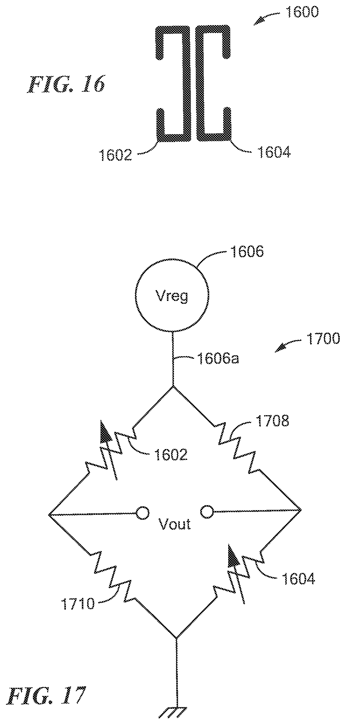
D00015
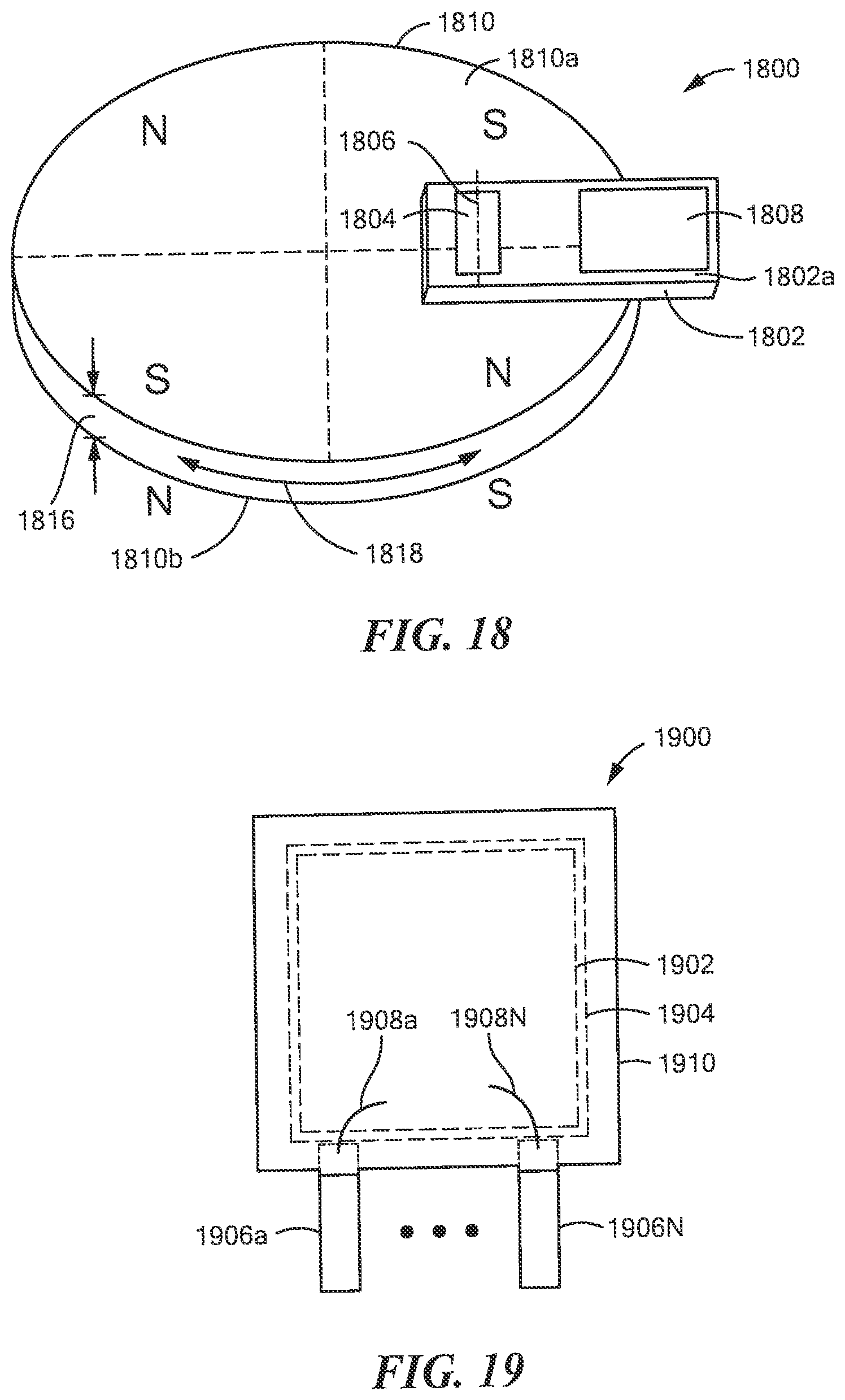
XML
uspto.report is an independent third-party trademark research tool that is not affiliated, endorsed, or sponsored by the United States Patent and Trademark Office (USPTO) or any other governmental organization. The information provided by uspto.report is based on publicly available data at the time of writing and is intended for informational purposes only.
While we strive to provide accurate and up-to-date information, we do not guarantee the accuracy, completeness, reliability, or suitability of the information displayed on this site. The use of this site is at your own risk. Any reliance you place on such information is therefore strictly at your own risk.
All official trademark data, including owner information, should be verified by visiting the official USPTO website at www.uspto.gov. This site is not intended to replace professional legal advice and should not be used as a substitute for consulting with a legal professional who is knowledgeable about trademark law.