Veneer underlayment
Schluter , et al. November 3, 2
U.S. patent number 10,822,812 [Application Number 16/543,346] was granted by the patent office on 2020-11-03 for veneer underlayment. This patent grant is currently assigned to Schluter Systems L.P.. The grantee listed for this patent is Schluter Systems L.P.. Invention is credited to Werner Schluter, Stefan Weige.


| United States Patent | 10,822,812 |
| Schluter , et al. | November 3, 2020 |
Veneer underlayment
Abstract
An underlayment for use between a veneer material and a foundation surface. The underlayment includes a base layer and a series of individual supports extending upwardly from the base layer and being configured to create voids in a layer of bonding material used to adhere the veneer material to the underlayment. Each of the individual supports includes at least one outer wall extending upwardly from the base layer, the outer wall extending at least partially around a perimeter of each of the supports. An internal wall is spaced from the outer wall and extends downwardly toward the base layer. A protrusion forms an overhang beneath which a heating element can be fitted. A liner material is bonded to an undersurface of the base layer and extends beneath the internal wall. A space is defined between the at least one outer wall, the internal wall and the liner material.
| Inventors: | Schluter; Werner (Iserlohn, DE), Weige; Stefan (Iserlohn, DE) | ||||||||||
|---|---|---|---|---|---|---|---|---|---|---|---|
| Applicant: |
|
||||||||||
| Assignee: | Schluter Systems L.P.
(Plattsburgh, NY) |
||||||||||
| Family ID: | 1000005156168 | ||||||||||
| Appl. No.: | 16/543,346 | ||||||||||
| Filed: | August 16, 2019 |
Prior Publication Data
| Document Identifier | Publication Date | |
|---|---|---|
| US 20190368205 A1 | Dec 5, 2019 | |
Related U.S. Patent Documents
| Application Number | Filing Date | Patent Number | Issue Date | ||
|---|---|---|---|---|---|
| 15790758 | Aug 27, 2019 | 10392814 | |||
| 15251929 | Oct 24, 2017 | 9797146 | |||
| 14523557 | Aug 30, 2016 | 9428920 | |||
| 13612527 | Feb 10, 2015 | 8950141 | |||
| Current U.S. Class: | 1/1 |
| Current CPC Class: | E04F 13/0885 (20130101); E04F 15/182 (20130101); E04F 15/185 (20130101); E04F 15/02194 (20130101); E04F 15/022 (20130101); E04F 15/082 (20130101) |
| Current International Class: | E04F 15/18 (20060101); E04F 13/08 (20060101); E04F 15/02 (20060101); E04F 15/022 (20060101); E04F 15/08 (20060101) |
References Cited [Referenced By]
U.S. Patent Documents
| 2737693 | March 1956 | Robbins |
| 2956785 | October 1960 | Richl |
| 3337167 | August 1967 | Johnson |
| 3434401 | March 1969 | Kiewit |
| 3597891 | August 1971 | Martin |
| 3624978 | December 1971 | Skinner |
| 3687771 | August 1972 | Meijer |
| 4016692 | April 1977 | Jordan et al. |
| D263628 | March 1982 | Platner |
| 4640067 | February 1987 | Hagemann et al. |
| 4640854 | February 1987 | Radtke |
| 4879857 | November 1989 | Peterson |
| 4905437 | March 1990 | Heather |
| 4917933 | April 1990 | Schluter |
| 4923733 | May 1990 | Herbst |
| 5042569 | August 1991 | Siegmund |
| 5052161 | October 1991 | Whitacre |
| 5082712 | January 1992 | Starp |
| 5105595 | April 1992 | Tokei |
| 5256007 | October 1993 | Allen |
| 5333432 | August 1994 | Schluter |
| 5374466 | December 1994 | Bleasdale |
| 5383314 | January 1995 | Rothberg |
| 5386670 | February 1995 | Takeda |
| 5412917 | May 1995 | Shelton |
| 5480259 | January 1996 | Thrower |
| 5489462 | February 1996 | Sieber |
| 5499476 | March 1996 | Adams |
| RE35369 | November 1996 | Ducroux |
| 5619832 | April 1997 | Myrvold |
| 5868399 | February 1999 | Schluter |
| 6094878 | August 2000 | Schluter |
| 6434901 | August 2002 | Schluter |
| 6539681 | April 2003 | Siegmund |
| 6672016 | January 2004 | Janesky |
| 6691472 | February 2004 | Hubert |
| 6786013 | September 2004 | Coulton |
| 6802668 | October 2004 | Parker |
| 6805298 | October 2004 | Corbett |
| 6918215 | July 2005 | Smith |
| 7108454 | September 2006 | Blackwood |
| 7250570 | July 2007 | Morand et al. |
| D555814 | November 2007 | Yin |
| 7536835 | May 2009 | Schluter |
| 7585556 | September 2009 | Julton |
| 7624551 | December 2009 | Thronicke |
| 7735280 | June 2010 | Valentine |
| 8176694 | May 2012 | Batori |
| 8288689 | October 2012 | Adelman |
| D706459 | June 2014 | Schluter et al. |
| 8950141 | February 2015 | Schluter |
| 9188348 | November 2015 | Larson |
| 9428920 | August 2016 | Schluter et al. |
| 9797146 | October 2017 | Schluter et al. |
| D857244 | August 2019 | Faotto et al. |
| D857933 | August 2019 | Julton et al. |
| 10392814 | August 2019 | Schluter et al. |
| 2001/0017015 | August 2001 | Schluter |
| 2006/0260233 | November 2006 | Schluter |
| 2008/0017725 | January 2008 | Backman, Jr. |
| 2008/0083833 | April 2008 | Blanke |
| 2008/0236097 | October 2008 | Tinianov |
| 2008/0276557 | November 2008 | Rapaz |
| 2008/0290503 | November 2008 | Karavakis |
| 2008/0290504 | November 2008 | Karavakis |
| 2008/0295441 | December 2008 | Carolan |
| 2009/0026192 | January 2009 | Fuhrman |
| 2009/0217605 | September 2009 | Batori |
| 2009/0230113 | September 2009 | Batori |
| 2010/0251641 | October 2010 | Gallagher |
| 2010/0319286 | December 2010 | Becker |
| 2011/0047907 | March 2011 | Smolka |
| 2014/0069039 | March 2014 | Schluter et al. |
| 2015/0167321 | June 2015 | Schluter et al. |
| 2016/0010327 | January 2016 | Larson |
| 2016/0033144 | February 2016 | Larson |
| 2016/0369517 | December 2016 | Schluter et al. |
| 2087055 | Jul 1994 | CA | |||
| 2317985 | Mar 2001 | CA | |||
| 2420097 | Aug 2003 | CA | |||
| 2456682 | Aug 2005 | CA | |||
| 2518285 | Mar 2006 | CA | |||
| 2533062 | Jul 2007 | CA | |||
| 1986165 | May 1968 | DE | |||
| 2650160 | May 1978 | DE | |||
| 2604782 | Jan 1979 | DE | |||
| 2840149 | Mar 1980 | DE | |||
| 3317131 | Nov 1984 | DE | |||
| 8633484 | Jul 1987 | DE | |||
| 3730144 | Apr 1988 | DE | |||
| 8812199 | Jan 1990 | DE | |||
| 3910629 | Oct 1990 | DE | |||
| 3916302 | Nov 1990 | DE | |||
| 9114591 | Mar 1993 | DE | |||
| 4238943 | Jan 1994 | DE | |||
| 202006013453 | Nov 2006 | DE | |||
| 102006004755 | Apr 2008 | DE | |||
| 0371268 | Feb 1993 | EP | |||
| 0561538 | Sep 1993 | EP | |||
| 1054217 | Nov 2000 | EP | |||
| 1063478 | Dec 2000 | EP | |||
| 1068413 | Oct 2003 | EP | |||
| 1460345 | Sep 2004 | EP | |||
| 1712695 | May 2013 | EP | |||
| 2746426 | Sep 1997 | FR | |||
| 2214947 | Sep 1989 | GB | |||
| WO 1982/003099 | Sep 1982 | WO | |||
| WO 1986/002120 | Apr 1986 | WO | |||
| WO 1987/003324 | Jun 1987 | WO | |||
| WO 1988/000997 | Feb 1988 | WO | |||
| WO 1993/014286 | Jul 1993 | WO | |||
| WO 1995/022671 | Aug 1995 | WO | |||
| WO 1999/055985 | Nov 1999 | WO | |||
| WO 2009/110934 | Sep 2009 | WO | |||
Other References
|
Exhibit B-1 "To Progress Profiles SPA's and Progress Profiles America's Response to Schluter Systems L.P's First Set of Interrogatories," pursuant to Imre Baton and Progress Profiles SPA vs. Schluter Systems L.P., Civil Action No. 1:15-cv-00144-CMH-IDD, presented Aug. 31, 2015, 8 pages. cited by applicant . Exhibit B-2, "To Progress Profiles SPA's and Progress Profiles America's Response to Schluter Systems L.P's First Set of Interrogatories," pursuant to Imre Baton and Progress Profiles SPA vs. Schluter Systems L.P., Civil Action No. 1:15-cv-00144-CHM-IDD, presented Aug, 31, 2015, 10 pages. cited by applicant . Exhibit B-3, "To Progress Profiles SPA's and Progress Profiles America's Response to Schluter Systems L.P's First Set of Interrogatories," pursuant to Imre Baton and Progress Profiles SPA vs. Schluter Systems L.P., Civil Action No. 1:15-cv-00144-CMH-IDD, presented Aug. 31, 2015, 7 pages. cited by applicant . Exhibit B-4, "To Progress Profiles SPA's and Progress Profiles America's Response to Schluter Systems L.P's First Set of Interrogatories," pursuant to Imre Baton and Progress Profiles SPA vs. Schluter Systems L.P., Civil Action No. 1:15-cv-00144-CMH-IDD, presented Aug. 31, 2015, 7 pages. cited by applicant . U.S. Appl. No. 29/432,009, filed Sep. 12, 2012; Werner Schluter; Notice of Allowance dated Feb. 5, 2014. cited by applicant. |
Primary Examiner: Ference; James M
Attorney, Agent or Firm: Jones; Jason R
Parent Case Text
PRIORITY CLAIM
This application is a continuation of U.S. patent application Ser. No. 15/790,758, filed Oct. 23, 2017 and issued as U.S. Pat. No. 10,392,814, which is a continuation of U.S. patent application Ser. No. 15/251,929, filed Aug. 30, 2016 and issued as U.S. Pat. No. 9,797,146, which is a continuation of U.S. patent application Ser. No. 14/523,557, filed Oct. 24, 2014 and issued as U.S. Pat. No. 9,428,920, which is a continuation of U.S. patent application Ser. No. 13/612,527, filed Sep. 12, 2012 and issued as U.S. Pat. No. 8,950,141, each of which is hereby incorporated herein by reference in its entirety.
Claims
The invention claimed is:
1. A tile installation, comprising: an underlayment disposed between a veneer material and a foundation surface, the underlayment comprising: a base layer; a series of individual supports extending upwardly from the base layer, each of the individual supports including: at least one outer wall extending upwardly from the base layer; an internal wall, coupled to and spaced from the outer wall; a liner material bonded to an undersurface of the base layer and extending beneath the internal wall, the liner material being bonded to the foundation surface beneath the internal wall; and a hollow space defined between and bounded by each of the at least one outer wall, the internal wall and the liner material; and a layer of bonding material, the layer of bonding material adhering to an undersurface of the veneer material and to a surface of the internal wall of each of the individual supports.
2. The installation of claim 1, wherein the series of individual supports comprises a first series of individual supports, and further comprising a second series of individual supports extending upwardly from the base layer, each of the second series of individual supports including an outer wall, each of the outer walls of the second series of individual supports opposing an outer wall of the first series of individual supports.
3. The installation of claim 2, wherein each of the outer walls of the second series of individual supports includes a protrusion extending therefrom beneath which a heating element can be fitted.
4. The installation of claim 1, wherein the outer wall extends substantially completely around a perimeter of each of the supports.
5. The installation of claim 1, further comprising an upper lip disposed between the outer wall and the internal wall, and wherein the internal wall slopes from the upper lip toward a center of the cavity and terminates at a support foot that is supported from an elevation substantially level with the base layer of the underlayment.
6. The installation of claim 5, wherein the upper lip includes a series of linear segments, and wherein the internal wall comprises a plurality of surfaces, each of the plurality of surfaces extending from one of the series of linear segments.
7. The installation of claim 1, wherein the internal wall includes a series of stepped plateaus formed therein.
8. The installation of claim 1, wherein the internal wall defines an at least partially conic cavity at least partially circumscribed by the outer wall.
9. The installation of claim 8, wherein the internal wall defines a plane that is angled from 40 degrees to 80 degrees from a center axis of the at least partially conic cavity.
10. The installation of claim 8, wherein the at least partially conic cavity includes at least one wall that defines a plane that is angled 60 degrees from a center axis of the at least partially conic cavity.
11. An underlayment for use between a veneer material and a foundation surface, the underlayment comprising: a base layer; a series of individual supports extending upwardly from the base layer and being configured to create voids in a layer of bonding material used to adhere the veneer material to the underlayment, each of the individual supports including: at least one outer wall extending upwardly from the base layer, the outer wall extending at least partially around a perimeter of each of the supports; an internal wall spaced from the outer wall and extending downwardly toward the base layer; a protrusion forming an overhang beneath which a heating element can be fitted; a liner material bonded to an undersurface of the base layer and extending beneath the internal wall; and a hollow space defined between and bounded by each of the at least one outer wall, the internal wall and the liner material.
12. The underlayment of claim 11, wherein the internal wall defines a cavity within the individual support, the cavity being at least partially conic.
13. The underlayment of claim 12, wherein the internal wall defines a plane that is angled from 40 degrees to 80 degrees from a center axis of the individual support.
14. The underlayment of claim 12, wherein at least a portion of the internal wall defines a plane that is angled from 50 degrees to 70 degrees from a center axis of the of the individual support.
15. The underlayment of claim 11, further comprising an upper lip disposed between the outer wall and the internal wall, and wherein the upper lip includes a series of linear segments, and wherein the internal wall comprises a plurality of surfaces, each of the plurality of surfaces extending from one of the series of linear segments of the upper lip.
16. The underlayment of claim 11, wherein the series of individual supports comprises a first series of individual supports, and further comprising a second series of individual supports extending upwardly from the base layer, each individual support of the second series of individual supports including an outer wall, each of the outer walls of the second series of individual supports opposing an outer wall of the first series of individual supports.
17. The underlayment of claim 16, wherein each of the individual supports of the second series of individual supports includes a protrusion extending therefrom beneath which a heating element can be fitted.
Description
FIELD OF THE INVENTION
The present invention relates generally planar support structures for use in veneer applications. While not so limited, the present invention is well suited for use in tiling and stone applications on floors, ceilings and walls.
BACKGROUND OF THE INVENTION
Centuries ago, European builders developed a reliable method of installing tile for high-traffic, high-use applications which relied upon a layer of "sand strata" between a structural substrate and a mortar-bed/tile composite top layer. Modern theory explains that the sand strata "uncouples" the tile from the structure, allowing structural movement without damage to the tile layer. However, due to space (height) requirements and other concerns, the sand strata method for tile installation is, for all practical purposes, extinct.
Approximately twenty-five years ago, a modern analog of the sand strata system was developed in which a thin, polyethylene sheet membrane functions as the uncoupling layer. This product, sold under the tradename DITRA, included a grid structure of square, cutback cavities and an anchoring fleece laminated to its underside. This membrane allows the normal loading forces exerted on the tile surface to be widely distributed through a forgiving shear plane, similar to that which would be expected in the sand strata. The resulting affect contradicted conventional theory which suggests that extremely strong bonds are necessary between the tile and the substrate to maintain a crack-free tile surface.
In fact, however, this system illustrated that a relatively weak interface is more forgiving, allowing substantial movement in the substrate without any evidence of cracking in the tile or the grout joints. This system also allows differential expansion and contraction between the tile and the substrate and can be used on a wide range of substrates which have traditionally been viewed as problematic; including plywood, OSB, post-tensioned concrete slabs, green concrete, radiant heated floors, and gypsum underlayments.
A direct, force-conductive bond of rigid materials such as ceramic or porcelain tile and stone is not suitable, since these surface materials are sensitive to tensile stresses, particularly when also exposed to live and dead loads. This fact becomes increasingly relevant since the formats of tile and stone are dramatically increasing in size. Twenty-five years ago, a 300 mm.times.300 mm (12''.times.12'') tile was considered very large. Today, formats of 900 mm.times.900 mm (3'.times.3') are commonly used and many modern manufacturers offer large formats up to 1200 mm.times.3000 mm (4'.times.10').
While the DITRA product performs well in many environments, the present inventors have improved on this revolutionary concept.
SUMMARY OF THE INVENTION
In accordance with one aspect of the technology, a tile installation is provided, including an underlayment disposed between a veneer material and a foundation surface. The underlayment can include a base layer and a series of individual supports extending upwardly from the base layer. Each of the individual supports can include at least one outer wall extending upwardly from the base layer, an internal wall, coupled to and spaced from the external wall, and a liner material bonded to an undersurface of the base layer and extending beneath the internal wall. The liner material can be bonded to the foundation surface beneath the internal wall. A space can be defined between the at least one outer wall, the internal wall and the liner material. A layer of bonding material can be adhered to an undersurface of the veneer material and to a surface of the internal wall of each of the individual supports.
In accordance with another aspect of the technology, an underlayment is provided for use between a veneer material and a foundation surface. The underlayment can include a base layer and a series of individual supports extending upwardly from the base layer and being configured to create voids in a layer of bonding material used to adhere the veneer material to the underlayment. Each of the individual supports can include at least one outer wall extending upwardly from the base layer, the outer wall extending at least partially around a perimeter of each of the supports. An internal wall can be spaced from the outer wall and can extend downwardly toward the base layer. A protrusion can form an overhang beneath which a heating element can be fitted. A liner material can be bonded to an undersurface of the base layer and can extend beneath the internal wall. A space can be defined between the at least one outer wall, the internal wall and the liner material.
There has thus been outlined, rather broadly, relatively important features of the invention so that the detailed description thereof that follows may be better understood, and so that the present contribution to the art may be better appreciated. Other features of the present invention will become clearer from the following detailed description of the invention, taken with the accompanying drawings and claims, or may be learned by the practice of the invention.
BRIEF DESCRIPTION OF THE DRAWINGS
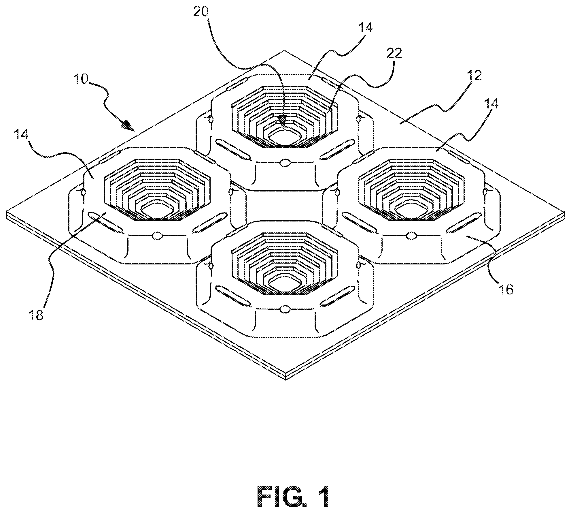
FIG. 1 is a top, perspective view of a segment of an underlayment in accordance with an embodiment of the invention;
FIG. 2 is a top view of the segment of underlayment of FIG. 1;
FIG. 3 is a side view of the segment of underlayment of FIG. 1; and
FIG. 4 is a sectional view of the underlayment of FIG. 1, taken along section A-A of FIG. 2 and shown installed as part of a tile installation with a heating element engaged between two adjacent supports.
DETAILED DESCRIPTION
Before the present invention is disclosed and described, it is to be understood that this invention is not limited to the particular structures, process steps, or materials disclosed herein, but is extended to equivalents thereof as would be recognized by those of ordinarily skilled in the relevant arts. It should also be understood that terminology employed herein is used for the purpose of describing particular embodiments only and is not intended to be limiting.
It must be noted that, as used in this specification and the appended claims, the singular forms "a" and "the" include plural referents, unless the context clearly dictates otherwise. Thus, for example, reference to a "support" can include one or more of such "supports."
Definitions
In describing and claiming the present invention, the following terminology will be used in accordance with the definitions set forth below.
As used herein, the term "veneer" is to be understood to refer broadly to a variety of materials that can be applied to floors, walls and ceilings and other structures to provide a decorative or protective finish to such structures. Examples of veneer material include, without limitation, ceramic tiles, natural or agglomerated stone tiles, glass tiles, or cementitious or epoxy terrazzo.
As used herein, the terms "upper," "lower," "elevation," "height," and the like, are to be understood to refer to relative locations and/or displacements of various elements or components relative to a condition in which a veneer system is oriented in its usable orientation. These terms are used to more clearly claim and describe the various elements or components of the invention and, unless the context clearly indicates otherwise, are not to be construed as limiting the invention to any particular embodiment.
As used herein, the term "substantially" refers to the complete or nearly complete extent or degree of an action, characteristic, property, state, structure, item, or result. As an arbitrary example, an object that is "substantially" enclosed is an object that is either completely enclosed or nearly completely enclosed. The exact allowable degree of deviation from absolute completeness may in some cases depend on the specific context. However, generally speaking the nearness of completion will be so as to have the same overall result as if absolute and total completion were obtained.
The use of "substantially" is equally applicable when used in a negative connotation to refer to the complete or near complete lack of an action, characteristic, property, state, structure, item, or result. As an arbitrary example, a composition that is "substantially free of" particles would either completely lack particles, or so nearly completely lack particles that the effect would be the same as if it completely lacked particles. In other words, a composition that is "substantially free of" an ingredient or element may still actually contain such item as long as there is no measurable effect thereof.
As used herein, the term "about" is used to provide flexibility to a numerical range endpoint by providing that a given value may be "a little above" or "a little below" the endpoint.
As used herein, a plurality of items, structural elements, compositional elements, and/or materials may be presented in a common list for convenience. However, these lists should be construed as though each member of the list is individually identified as a separate and unique member. Thus, no individual member of such list should be construed as a de facto equivalent of any other member of the same list solely based on their presentation in a common group without indications to the contrary.
Concentrations, amounts, and other numerical data may be expressed or presented herein in a range format. It is to be understood that such a range format is used merely for convenience and brevity and thus should be interpreted flexibly to include not only the numerical values explicitly recited as the limits of the range, but also to include all the individual numerical values or sub-ranges encompassed within that range as if each numerical value and sub-range is explicitly recited. As an illustration, a numerical range of "about 1 to about 5" should be interpreted to include not only the explicitly recited values of about 1 to about 5, but also include individual values and sub-ranges within the indicated range. Thus, included in this numerical range are individual values such as 2, 3, and 4 and sub-ranges such as from 1-3, from 2-4, and from 3-5, etc., as well as 1, 2, 3, 4, and 5, individually. This same principle applies to ranges reciting only one numerical value as a minimum or a maximum. Furthermore, such an interpretation should apply regardless of the breadth of the range or the characteristics being described.
Invention
As illustrated by example in the figures, the present invention generally provides an underlayment that can be utilized in a variety of applications in which a veneer material, such as ceramic tile or stone, is applied over a foundation surface, such as concrete, wood, engineered wood products, and the like. While not so limited, the underlayment can be formed from a generally pliable material including, without limitation, plastic such as polyethylene or polypropylene, metal, fabric, or a composite of different materials that allow deformation, maintain shape during installation, and result in a substantially incompressible interface between the veneer material and the foundation surface. In some embodiments, a bondable fleece or similar liner can be attached to a bottom surface of the underlayment to aid in bonding the underlayment to the foundation surface.
While the underlayment and related systems disclosed herein can be used in a variety of veneer applications, including those on floors, walls and ceilings, in the interest of simplicity, the discussion herein will focus on use of the system with ceramic tiles installed in a flooring application. It is to be understood, however, that the invention is not so limited.
The underlayment generally allows typical loading forces exerted on the tile surface to be widely distributed through a forgiving shear plane, similar to that which would be expected in the sand strata discussed above in the background section. Use of the present system can provide a relatively weak interface between the foundation surface and the tile. This interface is more forgiving, allowing substantial movement in the substrate without any evidence of cracking in the tile or the grout joints. The present system also allows differential expansion and contraction between the tile and the substrate and can be used on a wide range of substrates which have traditionally been viewed as problematic; including plywood, OSB, post-tensioned concrete slabs, green concrete, radiant heated floors, and gypsum underlayments, to name a few.
Turning now to the figures, in one aspect of the invention, an underlayment 10 is provided for use between a veneer material (see, e.g., tile 50 in FIG. 4) and a foundation surface (see, e.g., foundation surface 52 in FIG. 4). The underlayment can include a base layer 12 and a series of supports 14 that can extend upwardly from the base layer. The supports can be configured to create voids in the layer of adhesive bonding material used to adhere or bond the veneer material to the underlayment. These voids can weaken (or make less rigid) the interface between the generally very rigid veneer materials and the foundation surface. In the figures (particularly FIG. 4), these voids are represented by the space consumed by the supports in layer 54 of adhesive material. The present inventors configured these supports to improve dramatically over the original DITRA design. The volume and geometry of the bowl or cavity of the supports is optimized to correspondingly optimize the uncoupling capabilities of the underlayment, while maintaining (and potentially increasing) the ability to sustain loads.
Thus, the present design provides a forgiving interface beneath the veneer with greater ability to flex under load conditions where flexing is desirable, yet provides greater rigidity under load conditions where rigidity is more desirable. The resulting design, in essence, performs better in both loading conditions.
Each of the supports can include at least one outer wall 16 that can extend upwardly from the base layer and can terminate at an upper lip 18. A bowl area 20 can be defined adjacent a center of the support. The bowl area can be at least partially defined by an internal wall 22 that can extend downwardly from the upper lip toward the center of the support.
While the segments of the underlayment 10 shown in the figures include four supports 14, the underlayment will typically be provided in relatively large sheet rolls (on the order of one meter in width by as much as thirty meters in length) or sheet panels (on the order of one meter in width by as much as one meter twenty centimeters in length), with a great many of the supports 14 arrayed across the sheet. While not limiting the invention, to provide a general idea of the size of the supports, in one aspect the supports measure approximately one inch in width, and include a height of about 3/16 of an inch. The upper lip can include a width of about 1/8 of an inch.
In some embodiments, the outer wall 16 will extend substantially completely around a perimeter of each of the supports to define a closed geometry. In one aspect, the internal wall 22 slopes generally downwardly and inwardly from the upper lip 18 toward a center of the bowl area. Thus, the internal wall can define a conic cavity or bowl 20 that is at least partially circumscribed by the outer wall, and can be fully circumscribed by the outer wall. As best appreciated from FIG. 4, the conic cavity so defined can include at least one wall that forms an angle .alpha. relative to a center axis of the conic cavity. The angle .alpha. can vary: in one embodiment the angle measures from about 40 degrees to about 80 degrees. In another embodiment, the angle measures about 60 degrees.
Referring still to FIG. 4, the internal wall 22 that defines or forms the bowl or conic cavity 20 can extend downwardly and inwardly and can terminate at a support foot 24 that is supported at or from an elevation that is substantially level with the base layer of the underlayment. In this manner, loads carried by the adhesive or bonding material within the bowl area are transferred to substantially the same surface to which the base 12 of the underlayment is bonded.
While the cavity or bowl 20 is shown in the figures terminating flush with the base of the underlayment, it is also contemplated that the cavity can be formed with less of a depth, and the support foot can include a significantly larger height that will transfer the load carried by the support to the underlying foundation surface 52. Also, a spacer or other suitable blocking material (not shown) can be installed between the support foot and the underlying foundation surface.
As best appreciated from FIG. 4, the internal wall 22 can include a series of stepped plateaus or corrugations 26 formed therein. The steps or corrugations serve to provide greater flexibility to the wall, improve mechanical bond between dry-set mortar 54 and the underlayment, and increase the overall surface area of the internal wall.
FIG. 4 illustrates an application of the present system in which the underlayment is installed as a component of a veneer installation. The installation includes foundation surface 52 to which the underlayment is bonded via dry-set mortar or other suitable adhesive or bonding material 54. A bondable fleece or other liner material 28 can be bonded beneath the underlayment to increase the effectiveness of the bond between the underlayment and the foundation surface. Where applicable, the same dry-set mortar material 54 can be applied over the underlayment to secure tiles 50 to the underlayment. Grout 56 can then be applied between the tiles, as is well known in the art.
It will thus be appreciated that a hollow cavity 58 is defined beneath the internal wall 22 and above the liner material (when such is present) that remains hollow even after application of the tiles. This hollow space allows the supports 14 to flex in response to static and dynamic loads applied to the tiles to prevent cracking of the tiles and the grout, even in cases where such applied loads cause deflection of the foundation surface 52.
The supports 14 can include one or more protrusions 60 that can extend at least partially laterally from the outer wall of the support. The protrusion can thus create an overhang beneath which an open space is defined. The open space can advantageously trap or capture mortar (or other adhesive material) beneath the overhang, aiding in maintaining bonding of the underlayment to the foundation surface. Also, as shown in FIG. 4, two adjacent protrusions 60 extending from outer walls 16 can create a space within which a heating element 62 can be fitted. Thus, the present underlayment can be utilized in applications where it is desired to run electric or hydronic heating or cooling lines, or the like, beneath a tile installation.
In addition to the structural features described above, the present invention also provides various methods of forming, installing, and configuring underlayment systems in accordance with techniques known to those of ordinary skill in the art having possession of this disclosure.
It is to be understood that the above-described arrangements are only illustrative of the application of the principles of the present invention. Numerous modifications and alternative arrangements may be devised by those skilled in the art without departing from the spirit and scope of the present invention and the appended claims are intended to cover such modifications and arrangements. Thus, while the present invention has been described above with particularity and detail in connection with what is presently deemed to be the most practical and preferred embodiments of the invention, it will be apparent to those of ordinary skill in the art that numerous modifications, including, but not limited to, variations in size, materials, shape, form, function and manner of operation, assembly and use may be made without departing from the principles and concepts set forth herein.
* * * * *
D00000
D00001
D00002
D00003
XML
uspto.report is an independent third-party trademark research tool that is not affiliated, endorsed, or sponsored by the United States Patent and Trademark Office (USPTO) or any other governmental organization. The information provided by uspto.report is based on publicly available data at the time of writing and is intended for informational purposes only.
While we strive to provide accurate and up-to-date information, we do not guarantee the accuracy, completeness, reliability, or suitability of the information displayed on this site. The use of this site is at your own risk. Any reliance you place on such information is therefore strictly at your own risk.
All official trademark data, including owner information, should be verified by visiting the official USPTO website at www.uspto.gov. This site is not intended to replace professional legal advice and should not be used as a substitute for consulting with a legal professional who is knowledgeable about trademark law.