Use of an air-cleaning blower to keep condenser coils clean
Fennelly October 27, 2
U.S. patent number 10,816,260 [Application Number 15/530,931] was granted by the patent office on 2020-10-27 for use of an air-cleaning blower to keep condenser coils clean. This patent grant is currently assigned to CoilPod LLC. The grantee listed for this patent is Richard P. Fennelly. Invention is credited to Richard P. Fennelly.


| United States Patent | 10,816,260 |
| Fennelly | October 27, 2020 |
Use of an air-cleaning blower to keep condenser coils clean
Abstract
A refrigeration apparatus including an enclosure with an opening and condenser coils disposed within the enclosure, a cover plate dimensioned to fit over the opening, and with an air-cleaning blower apparatus placed over an orifice in the cover plate. The orifice in the cover plate is in communication with the interior of the enclosure holding the condenser coils, with the air-cleaning blower apparatus positioned in the incoming air stream to remove contaminants from the incoming air stream before the incoming air stream contacts the condenser coils. The cover plate may also have ports for introducing compressed air into the enclosure and for applying a vacuum to the enclosure, as well as an indicator for signaling the need for cleaning the condenser coils.
| Inventors: | Fennelly; Richard P. (Cortlandt Manor, NY) | ||||||||||
|---|---|---|---|---|---|---|---|---|---|---|---|
| Applicant: |
|
||||||||||
| Assignee: | CoilPod LLC (Yorktown Heights,
NY) |
||||||||||
| Family ID: | 1000005141903 | ||||||||||
| Appl. No.: | 15/530,931 | ||||||||||
| Filed: | March 24, 2017 |
Prior Publication Data
| Document Identifier | Publication Date | |
|---|---|---|
| US 20180156525 A1 | Jun 7, 2018 | |
Related U.S. Patent Documents
| Application Number | Filing Date | Patent Number | Issue Date | ||
|---|---|---|---|---|---|
| 62390915 | Apr 14, 2016 | ||||
| 62390318 | Mar 25, 2016 | ||||
| Current U.S. Class: | 1/1 |
| Current CPC Class: | F25B 47/00 (20130101); F25D 23/003 (20130101); F25B 39/04 (20130101) |
| Current International Class: | F25D 23/00 (20060101); F25B 47/00 (20060101); F25B 39/04 (20060101) |
| Field of Search: | ;62/89,100,125,303 |
References Cited [Referenced By]
U.S. Patent Documents
| 1967019 | July 1934 | Buchanan |
| 2525462 | October 1950 | Shell |
| 2665560 | January 1954 | Hubbard |
| 2811840 | November 1957 | Thompson |
| 3021686 | February 1962 | Alt |
| 3022639 | February 1962 | Brown |
| 3218819 | November 1965 | Crotser |
| 3344854 | October 1967 | Boyajian |
| 3518841 | July 1970 | West, Jr. |
| 3569806 | March 1971 | Brailsford |
| 3729773 | May 1973 | Dillon |
| 3736768 | June 1973 | Harbour |
| 3787114 | January 1974 | Catalano |
| 3978547 | September 1976 | Lawson |
| 4047393 | September 1977 | Hanson |
| 4102017 | July 1978 | Foerster |
| 4333201 | June 1982 | Rohner |
| 4344295 | August 1982 | Linstromberg |
| 4358933 | November 1982 | Horvay |
| 4370863 | February 1983 | Fisher |
| 4522036 | June 1985 | Van Gils |
| 4667580 | May 1987 | Wetzel |
| 4668898 | May 1987 | Harms |
| 4780927 | November 1988 | Clayton |
| 4839529 | June 1989 | Fruengel |
| 4865401 | September 1989 | Jacobson |
| 4928348 | May 1990 | Clayton |
| 4942805 | July 1990 | Hellwig |
| 5050667 | September 1991 | Berner |
| 5097678 | March 1992 | Aubuchon |
| 5211028 | May 1993 | Remo |
| 5226285 | July 1993 | Dankowski |
| 5285651 | February 1994 | Marine |
| 5333354 | August 1994 | Takemoto |
| 5515698 | May 1996 | Sawazaki |
| 6050101 | April 2000 | Liu |
| 6110246 | August 2000 | Eubank |
| 6293121 | September 2001 | Labrador |
| 6295696 | October 2001 | Harmon |
| 6792769 | September 2004 | Trulaske, Sr. |
| 6793715 | September 2004 | Sandberg |
| 6823684 | November 2004 | Jensen |
| 7024878 | April 2006 | Trulaske, Sr. |
| 7132017 | November 2006 | Laurence |
| 7477027 | January 2009 | Corbett |
| 7749310 | July 2010 | Lagerstedt |
| 7805953 | October 2010 | Jensen |
| 8182611 | May 2012 | Yoo |
| 8266813 | September 2012 | Grunert |
| 8590100 | November 2013 | Agorichas |
| 9222695 | December 2015 | Hasegawa |
| 9259675 | February 2016 | Roston |
| 9393599 | July 2016 | Seippel |
| 9638444 | May 2017 | Jokinen |
| 9803780 | October 2017 | Steinmann |
| 10081038 | September 2018 | Steinmann |
| 2003/0150226 | August 2003 | Jensen |
| 2004/0065107 | April 2004 | Bas |
| 2006/0080982 | April 2006 | Reichle |
| 2007/0062211 | March 2007 | Anderson |
| 2008/0034776 | February 2008 | Jensen |
| 2010/0236577 | September 2010 | Yoo |
| 2013/0160800 | June 2013 | Steinmann |
| 2015/0068710 | March 2015 | Reid |
| 2016/0123643 | May 2016 | Jokinen |
| 2016/0305148 | October 2016 | Poston |
Other References
|
Aero Conditioner Co., http:www.Picture.com/user/aeroconditioner/3860328360, Sep. 19, 2016. cited by applicant . www.aeroconditioner.com [How ACBS Duffer from filters and canisters]. Aug. 12, 2015 [Air Cleaners Used for Feed Air]. Aug. 12, 2015. cited by applicant. |
Primary Examiner: Ciric; Ljiljana V.
Attorney, Agent or Firm: Fennelly; Richard P.
Parent Case Text
This application claims the benefit of the following U.S. Provisional Patent Application Nos. 62/390,318, filed Mar. 25, 2016 and 62/390,915, filed Apr. 14, 2016.
Claims
I claim:
1. In a refrigeration apparatus including an enclosure and condenser coils located within the enclosure, the condenser coils being prone to become dirty over time as the condenser coils come in contact with an incoming air stream intended to promote heat transfer across the condenser coils, wherein the improvement comprises: a cover plate dimensioned to fit over an opening to the enclosure; an orifice in the cover plate, the orifice in communication with the interior of the enclosure; an air-cleaning blower apparatus operably positioned over the orifice and upstream of the condenser coils such that the incoming air stream enters the enclosure via the air-cleaning blower apparatus, thus allowing said air-cleaning blower apparatus to remove contaminants from the incoming air stream before the incoming air stream contacts the condenser coils.
2. The apparatus as claimed in claim 1, wherein the cover plate further comprises ports to allow the introduction of compressed air into the enclosure and/or to allow the application of a vacuum to the enclosure, respectively, thus allowing the condenser coils to be cleaned when they become dirty.
3. The apparatus as claimed in claim 1, wherein the cover plate further comprises an indicator to signal the need for cleaning the condenser coils should the condenser coils become dirty.
4. The apparatus as claimed in claim 1, wherein the cover plate further comprises ports to allow the introduction of compressed air into the enclosure and/or to allow the application of a vacuum to the enclosure, respectively, thus allowing the condenser coils to be cleaned when they become dirty, as well as further comprising an indicator to signal the need for cleaning the condenser coils should the condenser coils become dirty.
5. The apparatus as claimed in claim 2, wherein the cover plate further comprises an indicator to signal the need for cleaning the condenser coils should the condenser coils become dirty.
Description
This invention is applicable to cooling appliances, in general, either those that operate on the conventional refrigerant compression-expansion process or those newer technologies that are thermoelectric in nature.
Most conventional plug-in cooling appliances, such as refrigerators, freezers, display merchandisers, and the like, that operate on the compression-expansion process have condenser coil units that vent the heat that has been extracted from the chamber intended to be cooled to the atmosphere. These coil units generally sit in an enclosure behind a panel (or grille) having vents that allow air to enter for the needed airflow over the coils for the dissipation of heat therefrom. The condensing unit typically has a fan that draws air across the coils to facilitate the needed heat transfer to insure the unit is operating efficiently.
It is well-known that severe clogging contamination of the coils, often over a short period of time measured in the space of only a few months, with dust and other debris will rob these coils of their ability to perform their essential heat exchange function. Various solutions have been suggested to solve the problems associated with such "dirty" condenser coils in refrigeration units. Condensing units have been modified to include automated brushing means (see U.S. Patent Publication No. 2007/0062211) or the direction of rotation of the fan has been designed to reverse periodically (see U.S. Pat. Nos. 6,792,769 and 7,024,878). Some persons have recommended placing filter media over the panel or grille containing the vents to trap dust and other debris before it enters the enclosure holding the coils. Other solutions have involved periodic cleaning of dirty coils with appropriate dust containment devices when compressed air is employed (see U.S. Pat. Nos. 6,295,696, 8,182,611 and 8,590,100 and U.S. Patent Publication No. 2013/0160800, which covers the commercially available COILPOD dust containment bag, which is one preferred dust containment product).
The present invention is directed to a novel way of largely preventing dust contamination of the coils in the first place and is illustrated in the Drawings wherein:
FIG. 1 is a perspective view of the air cleaning blower which forms an essential component in the practice of the present invention;
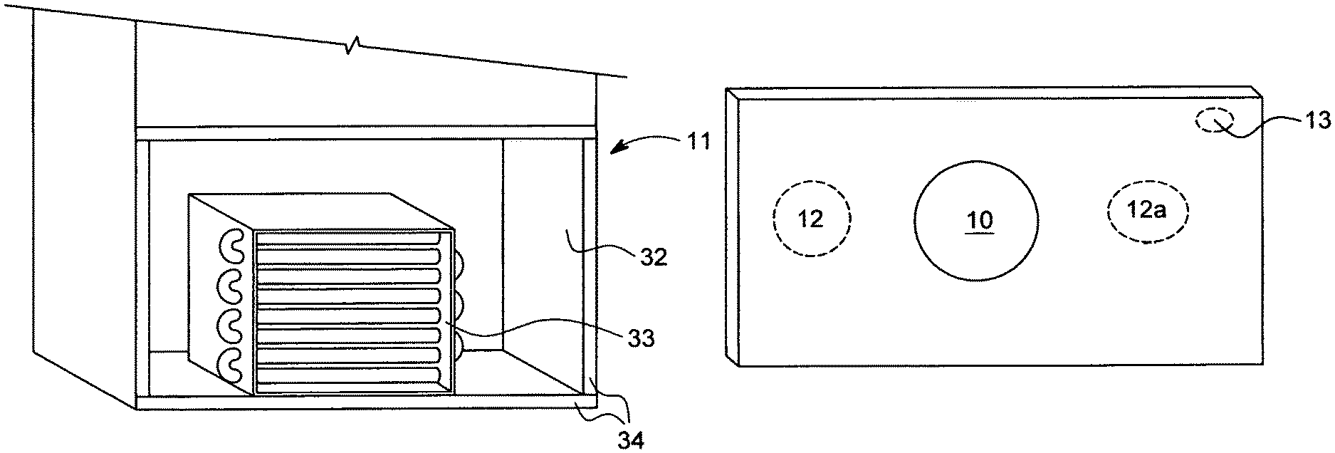
FIG. 2 is a perspective view of the front of a commercial-type refrigeration unit with the cover over the enclosure holding the unit's condenser coil unit removed; and
FIG. 3 is a perspective view of the type of novel cover that is employed by the present invention to close the opening to the enclosure that is illustrated in FIG. 2.
The instant invention involves replacing the conventional vented cover now used with a non-vented cover that also comprises an air-cleaning blower, which is shown in FIG. 1. This blower is placed over an orifice in the cover shown in FIG. 3. The orifice is in communication with the interior of the enclosure holding the condenser coils. The cover shown in FIG. 3 would be appropriately dimensioned to fit over the opening of the enclosure 32, depicted in FIG. 2, which holds the condenser coil unit 33 by affixation to surfaces 34 of the refrigeration unit 11.
One preferred conically-shaped air-cleaning blower unit, as depicted in FIG. 1, is described in U.S. Pat. No. 9,259,675, which is incorporated herein by reference. It is commercially available from Aero Conditioner LLC, Brooklyn, N.Y. 11205 (whose domain is aeroconditioner.com). This apparatus intakes air that is contaminated with all types of dust, debris, other particulates, and so forth and induces centripetal forces thereon to cause such contaminants to separate and be expelled from a different outlet located on the blower's periphery. This action is responsible for introduction of the cleansed air stream into the enclosure holding the condenser coils. The blower apparatus comprises an inlet, housing, impeller, and at least one clean air outlet and one particulate outlet.
The use of this air-cleaning blower unit can obviate the need for a fan assembly, as is conventional, in condensing units now in operation or it could be used in conjunction with such fan depending on the blowing power of the selected air-cleaning blower. It is well within the skill in the art to calibrate the needed blowing power of the blower and appropriately connect its electrical wiring to the condensing unit's fan power source(s) within the enclosure. When the refrigeration unit cycles on, the blower, either with or without the conventional condensing fan now commonly used, can cycle on as well to supply an air flow to promote coil heat transfer.
FIG. 3 shows an alternative cover plate containing the previously described air-cleaning blower 10, along with optional ports 12 and 12a (which would be covered in normal operation of the refrigeration unit to preserve the vent-less character of the cover). These ports are analogous to the ports contained in the dust containment bag described in U.S. Patent Publication No. 2013/0160800, which is commercially available under the trademark COILPOD. Such ports allow for coil cleaning, without removal of the cover plate, with a combination of sources of compressed air and vacuum, respectively placed in each of the ports once those ports are opened. If desired, an appropriate temperature indicator 13 can also be included, which can signal the presence of dirty coils, either visually or wirelessly. This indicator is connected to the condenser coils as described in U.S. Patent Publication No. 2015/0176932.
In order that the entire unit functions with the lowest electric energy possible, a preferred embodiment utilizes a special class of electric motor for both the fan in the condensing unit, if that is not deactivated, as well as in the air-cleaning blower. Rather than being either an induction (or shaded-pole) motor or the more recently developed electronically commutated motor, the preferred motor is the type of synchronous motor developed by and commercially available from QM Power, Inc. and designated the Q-SYNC Smart Synchronous Motor. This type motor, unlike an electronically commutated motor, does not require continual conversion between AC and DC power throughout its use to operate. The preferred motor's electronics get the motor to its targeted speed and then efficiently shift the motor to AC power supplied directly from the grid. Further details on this type of motor can be found in the following patent documents, which are incorporated herein by reference: U.S. Pat. Nos. 7,898,135; 8,810,084; 9,231,459; and 9,300,237 and U.S. Patent Publication No. 2016/0094113.
The other type of refrigeration apparatus that can be improved by the present invention operates thermo-electrically where a voltage of constant polarity is applied to a junction between two dissimilar electrical semiconductors where the negative one becomes cooler and the positive one hotter. A heat sink is used to dissipate the thermal energy from the positive one into the external environment as is well known to persons in the art. These heat sinks tend to collect dust and debris in an analogous manner to the condenser coils in the previously described compression-expansion refrigeration units. The enclosure holding such heat sink heat dissipation structure(s) will benefit in an analogous manner to the more conventional systems if the enclosure is closed off except for the previously described air cleaning blower being the source of air that is imported into the enclosure to assist in cooling the heat sink.
This invention also involves a new business method: (1) either retrofit or new unit manufacture of refrigeration apparatus, either non-residential or residential, employing the air-cleaning blower installation previously described; (2) coupled with an ongoing preventative maintenance program where the condenser coils (or heat sink) are cleaned, if needed, after being placed in service with a compressed air stream (e.g., compressed air, dry steam, or possibly liquid solvent stream) and vacuum using the previously COILPOD dust containment method and apparatus.
* * * * *
References
D00000
D00001
D00002
XML
uspto.report is an independent third-party trademark research tool that is not affiliated, endorsed, or sponsored by the United States Patent and Trademark Office (USPTO) or any other governmental organization. The information provided by uspto.report is based on publicly available data at the time of writing and is intended for informational purposes only.
While we strive to provide accurate and up-to-date information, we do not guarantee the accuracy, completeness, reliability, or suitability of the information displayed on this site. The use of this site is at your own risk. Any reliance you place on such information is therefore strictly at your own risk.
All official trademark data, including owner information, should be verified by visiting the official USPTO website at www.uspto.gov. This site is not intended to replace professional legal advice and should not be used as a substitute for consulting with a legal professional who is knowledgeable about trademark law.