Active suspension system with energy storage device
Katzourakis , et al. October 27, 2
U.S. patent number 10,814,690 [Application Number 15/935,293] was granted by the patent office on 2020-10-27 for active suspension system with energy storage device. This patent grant is currently assigned to APPLE INC.. The grantee listed for this patent is Johannes A. Huennekens, Diomidis Katzourakis, Paul J. Keas, Huibert Mees, Christopher L. Porritt. Invention is credited to Johannes A. Huennekens, Diomidis Katzourakis, Paul J. Keas, Huibert Mees, Christopher L. Porritt.


| United States Patent | 10,814,690 |
| Katzourakis , et al. | October 27, 2020 |
Active suspension system with energy storage device
Abstract
An active suspension system for a vehicle having a wheel that is subject to an external force includes an actuator having an output structure that is connected to the wheel, an energy storage device having a compressible chamber, a valve assembly that is operable to control flow of a working fluid between the actuator and the energy storage device, and a controller that determines whether to permit or resist motion of the output structure in response to the external force. The controller permits motion of the output structure by allowing fluid to flow from the actuator to the energy storage device using the valve assembly, thereby compressing the compressible chamber. The controller resists motion of the output structure by allowing fluid to flow from the energy storage device to the actuator using the valve assembly, thereby expanding the compressible chamber.
| Inventors: | Katzourakis; Diomidis (Chania, GR), Porritt; Christopher L. (Sunnyvale, CA), Huennekens; Johannes A. (San Jose, CA), Mees; Huibert (Pleasanton, CA), Keas; Paul J. (Sunnyvale, CA) | ||||||||||
|---|---|---|---|---|---|---|---|---|---|---|---|
| Applicant: |
|
||||||||||
| Assignee: | APPLE INC. (Cupertino,
CA) |
||||||||||
| Family ID: | 1000003270837 | ||||||||||
| Appl. No.: | 15/935,293 | ||||||||||
| Filed: | March 26, 2018 |
Related U.S. Patent Documents
| Application Number | Filing Date | Patent Number | Issue Date | ||
|---|---|---|---|---|---|
| 62486584 | Apr 18, 2017 | ||||
| Current U.S. Class: | 1/1 |
| Current CPC Class: | B60G 17/0155 (20130101); B60G 17/0165 (20130101); B60G 2202/412 (20130101); B60G 2202/416 (20130101); B60G 2202/414 (20130101); B60G 2202/44 (20130101); B60G 2500/30 (20130101); B60G 2400/64 (20130101); B60G 2202/413 (20130101); B60G 2600/182 (20130101); B60G 2204/62 (20130101) |
| Current International Class: | B60G 17/0165 (20060101); B60G 17/015 (20060101) |
| Field of Search: | ;701/37 |
References Cited [Referenced By]
U.S. Patent Documents
| 3781032 | December 1973 | Jones |
| 4530514 | July 1985 | Ito |
| 4537420 | August 1985 | Ito et al. |
| 4589678 | May 1986 | Lund |
| 4613152 | September 1986 | Booher |
| 4634142 | January 1987 | Woods et al. |
| 4637628 | January 1987 | Perkins |
| 4784378 | November 1988 | Ford |
| 4834416 | May 1989 | Shimoe et al. |
| 4893832 | January 1990 | Booher |
| 4922159 | May 1990 | Phillips et al. |
| 4960290 | October 1990 | Bose |
| 4981309 | January 1991 | Froeschle et al. |
| 4991698 | February 1991 | Hanson |
| 5033028 | July 1991 | Browning |
| 5060959 | October 1991 | Davis et al. |
| 5244053 | September 1993 | Kashiwagi |
| 5401053 | March 1995 | Sahm et al. |
| 5409254 | April 1995 | Minor et al. |
| 5468055 | November 1995 | Simon et al. |
| 5507518 | April 1996 | Nakahara et al. |
| 5517414 | May 1996 | Hrovat |
| 5678847 | October 1997 | Izawa et al. |
| 5810335 | September 1998 | Wirtz et al. |
| 5829764 | November 1998 | Griffiths |
| 5880542 | March 1999 | Leary et al. |
| 6032770 | March 2000 | Alcone et al. |
| 6113119 | September 2000 | Laurent et al. |
| 6170838 | January 2001 | Laurent et al. |
| 6249728 | June 2001 | Streiter |
| 6357770 | March 2002 | Carpiaux et al. |
| 6364078 | April 2002 | Parison et al. |
| 6443436 | September 2002 | Schel |
| 6470248 | October 2002 | Shank et al. |
| 6502837 | January 2003 | Hamilton et al. |
| 6634445 | October 2003 | Dix et al. |
| 6873891 | March 2005 | Moser et al. |
| 6926288 | August 2005 | Bender |
| 6940248 | September 2005 | Maresca et al. |
| 6945541 | September 2005 | Brown |
| 7017690 | March 2006 | Burke |
| 7032723 | April 2006 | Quaglia et al. |
| 7051851 | May 2006 | Svartz et al. |
| 7140601 | November 2006 | Nesbitt et al. |
| 7195250 | March 2007 | Knox et al. |
| 7202577 | April 2007 | Parison et al. |
| 7302825 | December 2007 | Knox |
| 7308351 | December 2007 | Knoop et al. |
| 7392997 | July 2008 | Sanville et al. |
| 7401794 | July 2008 | Laurent et al. |
| 7421954 | September 2008 | Bose |
| 7427072 | September 2008 | Brown |
| 7484744 | February 2009 | Galazin et al. |
| 7502589 | March 2009 | Howard et al. |
| 7543825 | June 2009 | Yamada |
| 7551749 | June 2009 | Rosen et al. |
| 7641010 | January 2010 | Mizutani et al. |
| 7644938 | January 2010 | Yamada |
| 7654540 | February 2010 | Parison et al. |
| 7818109 | October 2010 | Scully |
| 7823891 | November 2010 | Bushko et al. |
| 7932684 | April 2011 | O'Day et al. |
| 7962261 | June 2011 | Bushko et al. |
| 7963529 | June 2011 | Oteman et al. |
| 7976038 | July 2011 | Gregg |
| 8047551 | November 2011 | Morris et al. |
| 8067863 | November 2011 | Giovanardi |
| 8095268 | January 2012 | Parison et al. |
| 8099213 | January 2012 | Zhang et al. |
| 8109371 | February 2012 | Kondo et al. |
| 8112198 | February 2012 | Parison, Jr. et al. |
| 8113522 | February 2012 | Oteman et al. |
| 8127900 | March 2012 | Inoue |
| 8157036 | April 2012 | Yogo et al. |
| 8191874 | June 2012 | Inoue et al. |
| 8282149 | October 2012 | Kniffin et al. |
| 8336319 | December 2012 | Johnston et al. |
| 8356861 | January 2013 | Kniffin et al. |
| 8360387 | January 2013 | Breen et al. |
| 8370022 | February 2013 | Inoue et al. |
| 8387762 | March 2013 | Kondo et al. |
| 8417417 | April 2013 | Chen et al. |
| 8428305 | April 2013 | Zhang et al. |
| 8466639 | June 2013 | Parison, Jr. et al. |
| 8490761 | July 2013 | Kondo |
| 8499903 | August 2013 | Sakuta et al. |
| 8548678 | October 2013 | Ummethala et al. |
| 8579311 | November 2013 | Butlin, Jr. et al. |
| 8641052 | February 2014 | Kondo et al. |
| 8641053 | February 2014 | Pare et al. |
| 8668060 | March 2014 | Kondo et al. |
| 8682530 | March 2014 | Nakamura |
| 8701845 | April 2014 | Kondo |
| 8725351 | May 2014 | Selden et al. |
| 8744680 | June 2014 | Rieger et al. |
| 8744694 | June 2014 | Ystueta |
| 8757309 | June 2014 | Schmitt et al. |
| 8783430 | July 2014 | Brown |
| 8890461 | November 2014 | Knox et al. |
| 8938333 | January 2015 | Bose et al. |
| 9062983 | June 2015 | Zych |
| 9079473 | July 2015 | Lee et al. |
| 9102209 | August 2015 | Giovanardi et al. |
| 9291300 | March 2016 | Parker et al. |
| 9316667 | April 2016 | Ummethala et al. |
| 9349304 | May 2016 | Sangermano, II et al. |
| 9399384 | July 2016 | Lee et al. |
| 9533539 | January 2017 | Eng et al. |
| 9550495 | January 2017 | Tatourian et al. |
| 9625902 | April 2017 | Knox |
| 9643467 | May 2017 | Selden et al. |
| 9702349 | July 2017 | Anderson et al. |
| 9855887 | January 2018 | Potter et al. |
| 9868332 | January 2018 | Anderson et al. |
| 9975391 | May 2018 | Tseng et al. |
| 10065474 | September 2018 | Trangbaek |
| 10093145 | October 2018 | Vaughan et al. |
| 10245984 | April 2019 | Parker et al. |
| 10300760 | May 2019 | Aikin et al. |
| 10315481 | June 2019 | Lu et al. |
| 10377371 | August 2019 | Anderson et al. |
| 10513161 | December 2019 | Anderson et al. |
| 2003/0030241 | February 2003 | Lawson |
| 2004/0074720 | April 2004 | Thieltges |
| 2004/0226788 | November 2004 | Tanner |
| 2005/0051986 | March 2005 | Galazin et al. |
| 2005/0096171 | May 2005 | Brown et al. |
| 2005/0199457 | September 2005 | Beck |
| 2005/0206231 | September 2005 | Lu et al. |
| 2005/0247496 | November 2005 | Nagaya |
| 2006/0043804 | March 2006 | Kondou |
| 2006/0076828 | April 2006 | Lu et al. |
| 2006/0119064 | June 2006 | Mizuno et al. |
| 2006/0181034 | August 2006 | Wilde et al. |
| 2006/0266599 | November 2006 | Denys et al. |
| 2006/0273530 | December 2006 | Zuber |
| 2007/0069496 | March 2007 | Rinehart et al. |
| 2007/0107959 | May 2007 | Suzuki et al. |
| 2007/0199750 | August 2007 | Suzuki et al. |
| 2007/0210539 | September 2007 | Hakui et al. |
| 2008/0017462 | January 2008 | Mizutani et al. |
| 2008/0100020 | May 2008 | Gashi et al. |
| 2008/0283315 | November 2008 | Suzuki et al. |
| 2009/0033055 | February 2009 | Morris et al. |
| 2009/0064808 | March 2009 | Parison et al. |
| 2009/0095584 | April 2009 | Kondo et al. |
| 2009/0120745 | May 2009 | Kondo et al. |
| 2009/0121398 | May 2009 | Inoue |
| 2009/0173585 | July 2009 | Kappagantu |
| 2009/0174158 | July 2009 | Anderson et al. |
| 2009/0198419 | August 2009 | Clark |
| 2009/0218867 | September 2009 | Clark |
| 2009/0243402 | October 2009 | O'Day et al. |
| 2009/0243598 | October 2009 | O'Day |
| 2009/0273147 | November 2009 | Inoue et al. |
| 2009/0302559 | December 2009 | Doerfel |
| 2009/0321201 | December 2009 | Sakuta et al. |
| 2010/0044977 | February 2010 | Hughes et al. |
| 2010/0059959 | March 2010 | Kim |
| 2010/0222960 | September 2010 | Oida et al. |
| 2010/0252376 | October 2010 | Chern et al. |
| 2011/0115183 | May 2011 | Alesso et al. |
| 2012/0059547 | March 2012 | Chen et al. |
| 2012/0109483 | May 2012 | O'Dea et al. |
| 2012/0153718 | June 2012 | Rawlinson et al. |
| 2012/0187640 | July 2012 | Kondo et al. |
| 2012/0305348 | December 2012 | Katayama |
| 2012/0306170 | December 2012 | Serbu et al. |
| 2013/0060422 | March 2013 | Ogawa et al. |
| 2013/0060423 | March 2013 | Jolly |
| 2013/0106074 | May 2013 | Koku et al. |
| 2013/0221625 | August 2013 | Pare et al. |
| 2013/0229074 | September 2013 | Haferman et al. |
| 2013/0233632 | September 2013 | Kim et al. |
| 2013/0341143 | December 2013 | Brown |
| 2014/0260233 | September 2014 | Giovanardi |
| 2014/0312580 | October 2014 | Gale |
| 2014/0358378 | December 2014 | Howard et al. |
| 2015/0123370 | May 2015 | Lee et al. |
| 2015/0197130 | July 2015 | Smith et al. |
| 2015/0224845 | August 2015 | Anderson |
| 2015/0231942 | August 2015 | Trangbaek et al. |
| 2016/0059658 | March 2016 | Kuriki |
| 2016/0096458 | April 2016 | Parker et al. |
| 2016/0159187 | June 2016 | Mohamed |
| 2016/0167743 | June 2016 | Melcher |
| 2016/0291574 | October 2016 | Parison |
| 2016/0339823 | November 2016 | Smith et al. |
| 2017/0047823 | February 2017 | Sangermano, III et al. |
| 2017/0129367 | May 2017 | Hein |
| 2017/0129371 | May 2017 | Knox |
| 2017/0129372 | May 2017 | Hein et al. |
| 2017/0129373 | May 2017 | Knox et al. |
| 2017/0137023 | May 2017 | Anderson |
| 2017/0203673 | July 2017 | Parker et al. |
| 2017/0253101 | September 2017 | Kuriki |
| 2017/0253155 | September 2017 | Knox et al. |
| 2018/0089901 | March 2018 | Rober et al. |
| 2018/0105082 | April 2018 | Knox |
| 2018/0162186 | June 2018 | Anderson et al. |
| 2018/0162187 | June 2018 | Trangbaek |
| 2018/0297587 | October 2018 | Kasaiezadeh Mahabadi et al. |
| 2018/0345747 | December 2018 | Boon et al. |
| 2019/0248203 | August 2019 | Krehmer et al. |
| 2019/0308484 | October 2019 | Belter et al. |
| 2020/0088214 | March 2020 | Woodard et al. |
| 2020/0171907 | June 2020 | Hall et al. |
| 108215946 | Jun 2018 | CN | |||
| 208439009 | Jan 2019 | CN | |||
| 102009060213 | Jun 2011 | DE | |||
| 202012002846 | Jul 2012 | DE | |||
| 102015003530 | Sep 2016 | DE | |||
| 102016000686 | Jul 2017 | DE | |||
| 102018208774 | Dec 2019 | DE | |||
| 2072855 | Jun 2009 | EP | |||
| 2233330 | Feb 2013 | EP | |||
| 3088230 | Nov 2016 | EP | |||
| 2437633 | Oct 2007 | GB | |||
| 2006200734 | Aug 2006 | JP | |||
| 5796315 | Oct 2015 | JP | |||
| 101509600 | Apr 2015 | KR | |||
| 9304883 | Mar 1993 | WO | |||
| 2012028228 | Mar 2012 | WO | |||
| 2014004118 | Jan 2014 | WO | |||
| 2014004119 | Jan 2014 | WO | |||
| 2014094934 | Jun 2014 | WO | |||
| 2015153811 | Oct 2015 | WO | |||
| 2015169530 | Nov 2015 | WO | |||
| 2016120044 | Aug 2016 | WO | |||
| 2017055151 | Apr 2017 | WO | |||
Other References
|
Monroe Intelligent Suspension, "CVSA2/Kinetic: Low Energy for High Performance", www.monroeintelligentsuspension.com/products/cvsa2-kinetic/, Date Unknown, Downloaded Mar. 2, 2017, 2 pp. cited by applicant . Tenneco, "Integrated Kinetic, H2 CES System, Ride Control Innovation, Accelerated", Rev. Sep. 2011, 4 pp. cited by applicant . Wikipedia, "Trailing-arm suspension", https://en.wikipedia.org/wiki/Trailing-arm_suspension, downloaded Sep. 3, 2019 (2 pp). cited by applicant . Daimler.com, "Suspension: The world's first suspension system with `eyes`", https://media.daimler.com/ marsMediaSite/en/instance/ko/Suspension-The-worlds-first-suspension-syste- m-with-eyes.xhtml?oid=9904306, May 15, 2013 (6 pp). cited by applicant . Youtube.com, KSSofficial, "Miniature Ball Screw With Ball Spline / English", Published on May 10, 2013, https://www.youtube.com/watch?v=vkcxmM0iC8U (2 pp). cited by applicant . Nippon Bearing, "Ball Screw Spline SPBR/SPBF", Product Description, Date Unknown, Downloaded Jun. 28, 2019, https://www.nbcorporation.com/shop/ball-spline/spbr-spbf/ (2 pp). cited by applicant . Porsche.com, "Porsche AG: Porsche 918 RSR--Racing Laboratory With Even Higher-Performance Hybrid Drive--Porsche USA", Current Press Releases dated Jan. 10, 2011, Downloaded Mar. 13, 2017, www. porsche.com/usa/aboutporsche/pressreleases/pag/?pool=international-de&id-- 2011-01-10, 6 pp. cited by applicant . Autoblog.com, "Porsche (finally) Unleashes Full, Official Details in 918 Spyder--Autoblog", Sep. 9, 2013, www.autoblog.com/2013/09/09/porsche-official-detials-918-spyder-frankfurt- /, Downloaded Mar. 13, 2017, 26 pp. cited by applicant . Press.porsche.com, "Introducing the Porsche 918 Spyder", Date Unknown, http://press.porsche.com/news/release.php?id-787, Downloaded Mar. 13, 2017, 7 pp. cited by applicant . Edren, Johannes, "Motion Modelling and Control Strategies of Over-Actuated Vehicles", Doctoral Thesis, Stockholm 2014 (56 pp). cited by applicant . Bolognesi, P., et al., "FEM Modeling and Analysis of a Novel Rotary-Linear Isotropic Brushless Machine", XIX International Conference of Electrical Machines--ICEM 2010, Rome (6 pp). cited by applicant . Xu, Lei, et. al., "Design and Analysis of a Double-Stator Linear-Rotary Permanent-Magnet Motor", IEEE Transactions on Applied Superconductivity, vol. 26, No. 4, Jun. 2016, (4 pp). cited by applicant . SAE International, "Michelin re-invents the wheel", Oct. 14, 2008, Downloaded Sep. 7, 2017, http://articles.sae.org/4604/ (2 pp). cited by applicant . Cosford, J., "Is it a fair fight? Hydraulics vs. electrics", https://www.mobilehydraulictips.com/fair-fight-hydraulics-vs-electrics/, Mar. 28, 2014 (10 pp). cited by applicant. |
Primary Examiner: Soofi; Yazan A
Attorney, Agent or Firm: Young Basile Hanlon & MacFarlane, P.C.
Parent Case Text
CROSS-REFERENCE TO RELATED APPLICATIONS
This application claims the benefit of U.S. Provisional Application No. 62/486,584, entitled "Active Suspension System with Energy Storage Device," filed on Apr. 18, 2017, the content of which is incorporated herein by reference in its entirety.
Claims
What is claimed is:
1. An active suspension system for a vehicle having a wheel that is subject to an external force, comprising: an actuator having an output structure that is connected to the wheel such that the external force acts on the output structure; an energy storage device having a compressible chamber; a valve assembly that is positioned in fluid communication between the actuator and the energy storage device and is operable to control flow of a working fluid between the actuator and the energy storage device; and a controller that makes a determination to permit motion of the output structure in response to the external force or to resist motion of the output structure in response to the external force, and controls the valve assembly according to the determination.
2. The active suspension system of claim 1, wherein: the controller permits motion of the output structure when a desired travel direction for the output structure matches an external force direction, and the controller resists motion of the output structure when a desired travel direction for the output structure is opposite the external force direction, the controller permits motion of the output structure by controlling the valve assembly to allow fluid to flow from the actuator to the energy storage device using the valve assembly, thereby compressing the compressible chamber, and the controller resists motion of the output structure by controlling the valve assembly to allow fluid to flow from the energy storage device to the actuator using the valve assembly, thereby expanding the compressible chamber.
3. The active suspension system of claim 1, wherein a compressible medium is disposed in the compressible chamber.
4. The active suspension system of claim 3, wherein the compressible medium is a gas.
5. The active suspension system of claim 4, further comprising: a pressure regulator for increasing and decreasing a gas pressure within the compressible chamber.
6. The system of claim 1, wherein an elastic structure is disposed within the compressible chamber.
7. The system of claim 1, wherein an energy storage actuator is disposed within the compressible chamber.
8. The system of claim 1, wherein the working fluid is a magnetorheological hydraulic fluid and the valve assembly includes electromagnetic coils.
9. The system of claim 1, further comprising: a low-pressure reservoir that stores a portion of the working fluid; and a pump that is connected to the low-pressure reservoir to supply the working fluid from the low-pressure reservoir to the valve assembly.
10. The system of claim 1, wherein the energy storage device is connected to the valve assembly by a two-directional flow line.
11. A system, comprising: a hydraulic actuator having a body, a piston rod that extends out of the body, a piston head disposed in the body, a first volume defined inside the body on a first side of the piston head, and a second volume defined inside the body on a second side of the piston head; an energy storage device having a housing, a first chamber defined inside the housing, a second chamber defined inside the housing, and a compressible chamber defined inside the housing; a first valve assembly that is operable to control flow of a working fluid between the first volume of the hydraulic actuator and the first chamber of the energy storage device; a second valve assembly that is operable to control flow of the working fluid between the second volume of the hydraulic actuator and the second chamber of the energy storage device; and a controller that controls operation of at least one of the first valve assembly or the second valve assembly to store energy in the energy storage device by compressing the compressible chamber by flow of the working fluid into the energy storage device from the hydraulic actuator when a desired travel direction for the piston rod matches an external force direction, and controls operation of at least one of the first valve assembly or the second valve assembly to release energy from the energy storage device by expanding the compressible chamber by flow of the working fluid into the hydraulic actuator from the energy storage device when the desired travel direction for the piston rod is opposite the external force direction.
12. The system of claim 11, wherein the energy storage device is configured such that the compressible chamber is located between the first chamber and the second chamber.
13. The system of claim 12, wherein flow of the working fluid into the first chamber is operable to compress the compressible chamber and flow of the working fluid into the second chamber is operable to compress the compressible chamber.
14. The system of claim 11, wherein a compressible gas is located in the compressible chamber.
15. The system of claim 14, further comprising: a pressure regulator that is operable to increase and decrease an amount of the compressible gas that is located in the compressible chamber.
16. The system of claim 11, wherein a compression spring is located in the compressible chamber.
17. The system of claim 11, wherein the first valve assembly is connected to the first chamber of the energy storage device by a first two-directional flow line and the second valve assembly is connected to the second chamber of the energy storage device by a second two-directional flow line.
18. A method, comprising: determining a desired direction of travel for an actuator; determining an external force direction of an external force that is applied to the actuator; determining whether the external force direction matches the desired direction of travel for the actuator; in response to determining that the external force direction matches the desired direction of travel for the actuator, controlling a valve assembly to cause storage of energy from the actuator in an energy storage device by compressing a compressible chamber of the energy storage device by flow of a working fluid into the energy storage device from the actuator, wherein the valve assembly is positioned in fluid communication between the actuator and the energy storage device and is configured to control flow of the working fluid between the actuator and the energy storage device along a two-directional flow line; and in response to determining that the external force direction does not match the desired direction of travel for the actuator, controlling the valve assembly to cause release of energy from the energy storage device to the actuator by expanding a compressible chamber of the energy storage device by flow of the working fluid from the energy storage device to the actuator.
19. The method of claim 18, wherein the valve assembly is configured to establish flow of the working fluid between the actuator and the energy storage device along the two-directional flow line and to block flow of the working fluid between the actuator and the energy storage device along the two-directional flow line.
20. The method of claim 18, wherein a compressible medium is located in the compressible chamber.
Description
TECHNICAL FIELD
The application relates generally to active suspension systems.
BACKGROUND
Active suspension systems incorporate actuators that are controlled by an external controller to change the ride characteristics of a vehicle in response to sensed conditions. Functions performed by active suspension systems can include, for example, controlling the vertical movement of the wheels of the vehicle relative to a vehicle body of the vehicle, controlling damping firmness at each of the wheels, and self-levelling.
SUMMARY
One aspect of the disclosed embodiments is an active suspension system for a vehicle having a wheel that is subject to an external force. The active suspension system includes an actuator having an output structure that is connected to the wheel, an energy storage device having a compressible chamber, a valve assembly that is operable to control flow of a working fluid between the actuator and the energy storage device, and a controller that determines whether to permit or resist motion of the output structure in response to the external force. The controller permits motion of the output structure by allowing fluid to flow from the actuator to the energy storage device using the valve assembly, thereby compressing the compressible chamber. The controller resists motion of the output structure by allowing fluid to flow from the energy storage device to the actuator using the valve assembly, thereby expanding the compressible chamber.
Another aspect of the disclosed embodiments is a system that includes a hydraulic actuator having a body, a piston rod that extends out of the body, a piston head disposed in the body, an upper volume defined inside the body on a first side of the piston head, and a lower volume defined inside the body on a second side of the piston head. The system also includes an energy storage device having a housing, an upper chamber defined inside the housing, a lower chamber defined inside the housing, and a compressible chamber defined inside the housing. The system also includes an upper valve assembly that is operable to control flow of a working fluid between the upper volume of the hydraulic actuator and the upper chamber of the energy storage device. The system also includes a lower valve assembly that is operable to control flow of the working fluid between the lower volume of the hydraulic actuator and the lower chamber of the energy storage device. The system also includes a controller that controls of operation at least one of the upper valve assembly or the lower valve assembly to store energy in the energy storage device by compressing the compressible chamber by flow of the working fluid into the energy storage device from the hydraulic actuator when a desired travel direction for the piston rod matches an external force direction. The controller controls operation of at least one of the upper valve assembly or the lower valve assembly to release energy from the energy storage device by expanding the compressible chamber by flow of the working fluid into the hydraulic actuator from the energy storage device when the desired travel direction for the piston rod is opposite the external force direction.
Another aspect of the disclosed embodiments is a method that includes determining a desired direction of travel for an actuator, determining an external force direction of an external force that is applied to the actuator, and determining whether the external force direction matches the desired direction of travel for the actuator. In response to determining that the external force direction matches the desired direction of travel for the actuator, the method includes controlling a valve assembly to cause storage of energy from the actuator in an energy storage device by compressing a compressible chamber of the energy storage device by flow of a working fluid into the energy storage device from the actuator. In response to determining that the external force direction does not match the desired direction of travel for the actuator, the method includes controlling the valve assembly to cause release of energy from the energy storage device to the actuator by expanding a compressible chamber of the energy storage device by flow of the working fluid from the energy storage device to the actuator.
BRIEF DESCRIPTION OF THE DRAWINGS
FIG. 1 is an illustration that shows a portion of a vehicle that has a hydraulic actuator, an actuation system, and a suspension system controller.
FIG. 2 is a block diagram that shows the actuation system.
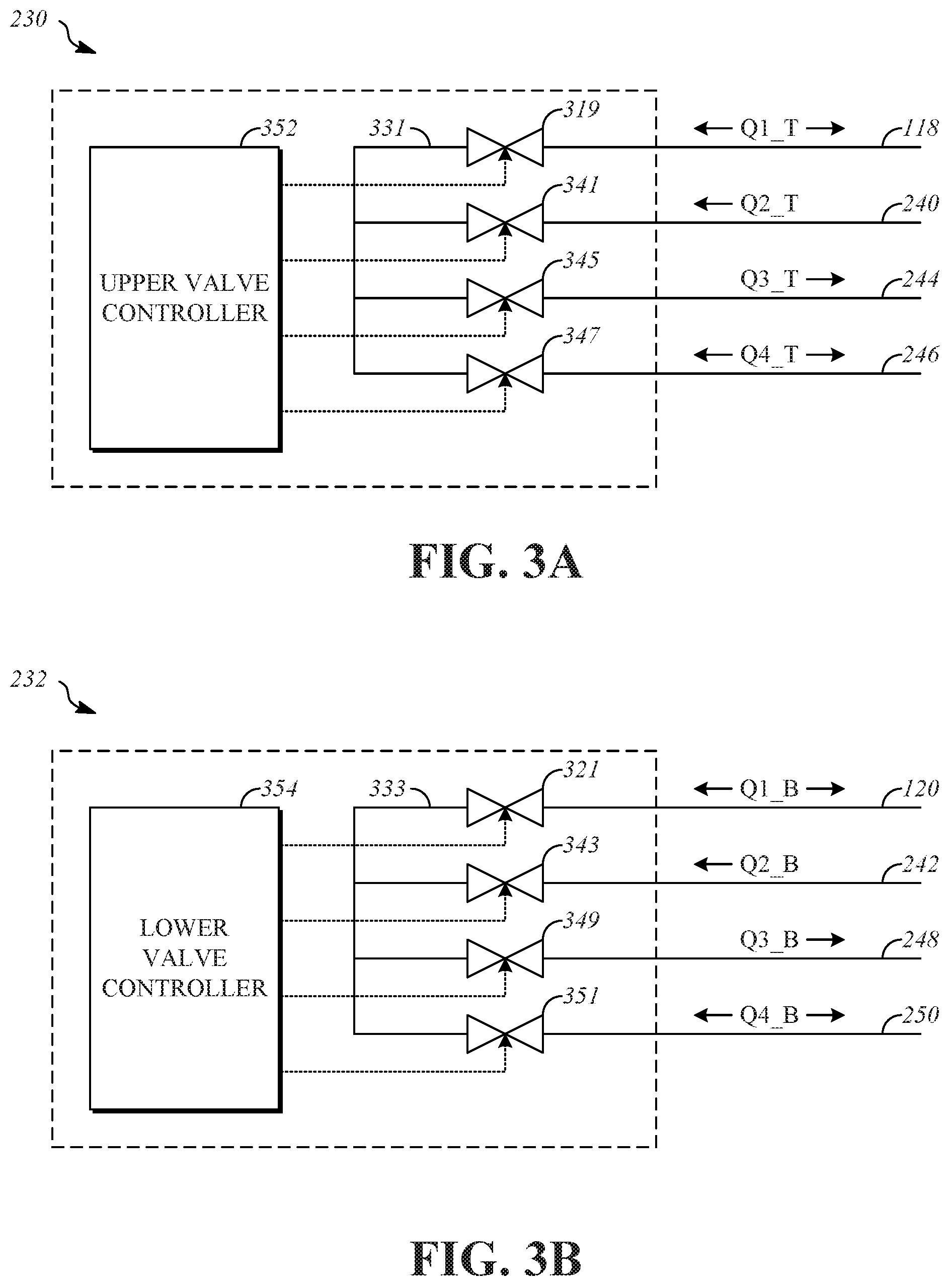
FIG. 3A is a diagram that shows an upper valve assembly of the actuation system.
FIG. 3B is a diagram that shows a lower valve assembly of the actuation system.
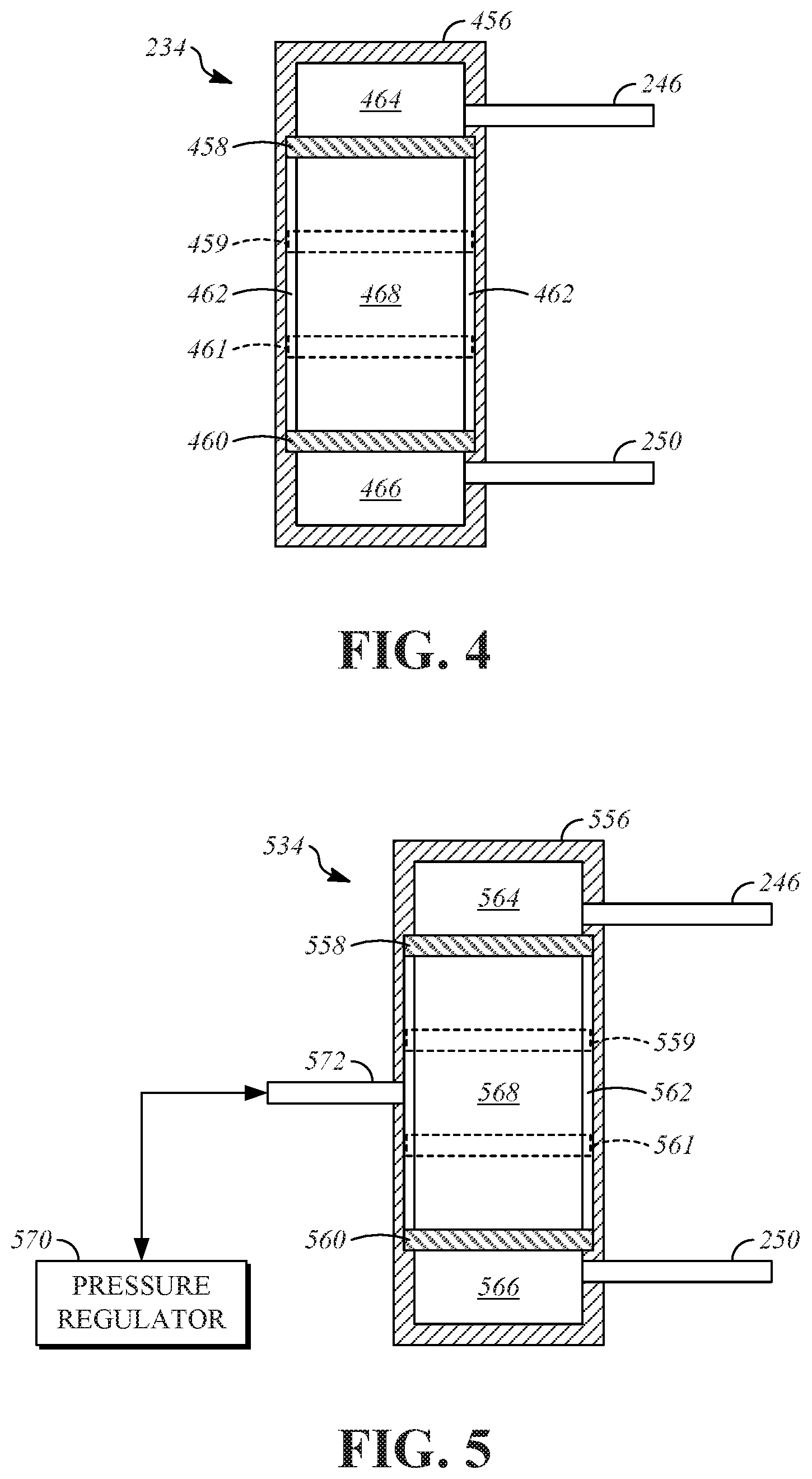
FIG. 4 is a diagram that shows an energy storage device of the actuation system according to a first example.
FIG. 5 is a diagram that shows an energy storage device of the actuation system according to a second example.
FIG. 6 is a diagram that shows an energy storage device of the actuation system according to a third example.
FIG. 7 is a diagram that shows an energy storage device of the actuation system according to a fourth example.
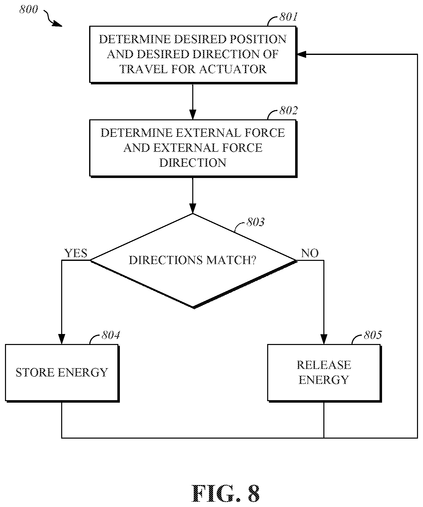
FIG. 8 is a flowchart that shows an example of a control process for an active suspension system with an energy storage device.
DETAILED DESCRIPTION
The disclosure herein relates to an active suspension that includes a hydraulic actuator and an energy storage device. The energy storage device includes a compressible medium or an elastic structure that is compressed by fluid flow resulting from external forces that are applied to the hydraulic actuator. Valves control fluid flow to and from the energy storage device so that stored energy can be retained and later released when needed to supply fluid pressure to the hydraulic actuator.
FIG. 1 shows a portion of a vehicle 100 that has a vehicle body 102. The vehicle body 102 may include internal structural portions and external portions that are aesthetic and/or structural in nature. As examples, the vehicle body 102 may include one or more of a unibody, a frame, a subframe, a monocoque, and body panels.
The vehicle 100 includes a road wheel 104. The road wheel 104 is one of multiple (e.g., four) wheels that can be included as part of the vehicle 100 to contact the surface on which the vehicle 100 is travelling. The characteristics of the road wheel 104 are responsible, in part, for the amount of friction available, and the road wheel 104 therefore includes a friction enhancing structure such as a conventional pneumatic tire that is formed in part from synthetic rubber.
The road wheel 104 is mechanically connected to the vehicle body 102 in a manner that allows motion of the road wheel 104 relative to the vehicle body 102. This connection includes a hydraulic actuator 106 that is operable to dampen motion of the road wheel 104 relative to the vehicle body 102. The hydraulic actuator 106 is an actively controlled component having one or more adjustable characteristics, as will be described herein. During operation of the vehicle 100, the road wheel 104 is subjected to external forces F_ext, and the hydraulic actuator 106 can be controlled to react to the external forces F_ext in a desired manner.
The hydraulic actuator 106 includes a cylinder body 108, a moveable output structure such as a piston rod 110 that extends out of the cylinder body 108, and a piston head 112 that is located inside the cylinder body 108. An internal space of the cylinder body 108 is divided by the piston head 112 into an upper volume 114 and a lower volume 116. The upper volume 114 is located inside the cylinder body 108 on a first side of the piston head 112. The lower volume 116 is located inside the cylinder body 108 on a second side of the piston head 112. An upper hydraulic feed line 118 is connected to the cylinder body 108 to supply fluid to and receive fluid from the upper volume 114. A lower hydraulic feed line 120 is connected to the cylinder body 108 to supply fluid to and receive fluid from the lower volume 116.
The upper hydraulic feed line 118 and the lower hydraulic feed line 120 of the hydraulic actuator 106 are connected to an actuation system 122. The actuation system 122 is operable to regulate transmission of fluid to and from the hydraulic actuator 106 in order to control the operating characteristics of the hydraulic actuator 106. As will be explained herein, the actuation system 122 includes hydraulic components that facilitate fluid flow and electrical components that can be controlled by commands in the form of signals and/or data to allow operation of the actuation system 122 by an external controller. In the illustrated example, the actuation system 122 receives commands from a suspension system controller 124 over an electrical connection, for example, a data network that complies with the Controller Area Network standard.
The suspension system controller 124 is operable to control operation of the actuation system 122 and other active suspension components. The suspension system controller 124 can include a memory and a processor that is operable to execute instructions that are stored in the memory in order to perform suspension control operations. The suspension system controller 124 determines and outputs commands that are transmitted to the actuation system 122. The commands, when executed by the suspension system controller 124, modify one or more operating characteristics of the actuation system 122. The suspension system controller 124 can receive information from sensors, such as sensors associated with the hydraulic actuator 106, and determine the commands based on the information received from the sensors.
FIG. 2 is block diagram that shows the actuation system 122. The actuation system 122 includes a low-pressure accumulator 226, a pump 228, an upper valve assembly 230, a lower valve assembly 232, and an energy storage device 234.
The low-pressure accumulator 226 serves as a reservoir for excess quantities of a working fluid that is used by the hydraulic actuator 106. The working fluid is a hydraulic fluid, such as an oil (or other liquid), and is incompressible.
The low-pressure accumulator 226 is connected to the pump 228 by a pump supply line 236. The pump supply line 236 allows transmission of the working fluid from the low-pressure accumulator 226 to the pump 228. A one-way flow valve 238 can be included along the pump supply line 236 so that fluid flows only from the low-pressure accumulator 226 to the pump 228, and backflow from the pump 228 to the low-pressure accumulator 226 is prevented.
The pump 228 provides the working fluid to the upper valve assembly 230 and the lower valve assembly 232. The pump 228 is connected to the upper valve assembly 230 by an upper valve supply line 240. The pump 228 is connected to the lower valve assembly 232 by a lower valve supply line 242.
The upper valve assembly 230 is connected to multiple components of the actuation system 122, and regulates flow of the working fluid to and from these components by controlling the states of multiple valves, which will be discussed further herein. The upper valve assembly 230 is connected to the upper hydraulic feed line 118 to allow the upper valve assembly 230 to supply the working fluid to the upper volume 114 of the hydraulic actuator 106 and to receive the working fluid from the upper volume 114 of the hydraulic actuator 106. The upper valve assembly 230 is connected to the low-pressure accumulator 226 by an upper return line 244 to return an excess volume of the working fluid from the upper valve assembly 230 to the low-pressure accumulator 226. The upper valve assembly 230 is connected to the energy storage device 234 by an upper energy storage line 246 to supply the working fluid to the energy storage device 234 and to receive the working fluid from the energy storage device 234.
The lower valve assembly 232 is connected to multiple components of the actuation system 122, and regulates flow of the working fluid to and from these components by controlling the states of multiple valves, which will be discussed further herein. The lower valve assembly 232 is connected to the hydraulic feed line 120 to allow the lower valve assembly 232 to supply the working fluid to the lower volume 116 of the hydraulic actuator 106 and to receive the working fluid from the lower volume 116 of the hydraulic actuator 106. The lower valve assembly 232 is connected to the low-pressure accumulator 226 by a lower return line 248 to return an excess volume of the working fluid from the lower valve assembly 232 to the low-pressure accumulator 226. The lower valve assembly 232 is connected to the energy storage device 234 by a lower energy storage line 250 to supply the working fluid to the energy storage device 234 and to receive the working fluid from the energy storage device 234.
As will be explained further herein, the energy storage device 234 includes a compressible medium that is compressed elastically by flow of the working fluid to the energy storage device 234 through the upper energy storage line 246 and the lower energy storage line 250. The flow of the working fluid to the energy storage device 234 can result from the external forces F_ext that are applied to the hydraulic actuator 106. The pressures generated by the external forces F_ext are sufficient to allow the working fluid to flow into the energy storage device 234 from the hydraulic actuator 106 and compress the compressible medium without additional pumping. Conversely, the pressures generated by compressing the compressible medium are sufficient to allow the working fluid to flow into the hydraulic actuator 106 from the energy storage device 234 and cause motion of the piston rod 110 without additional pumping. By controlling the upper valve assembly 230 and the lower valve assembly 232, this energy can be retained in the energy storage device 234 and subsequently released to assist operation of the hydraulic actuator 106. Use of the energy stored by the energy storage device 234 to operate the hydraulic actuator 106 can allow the actuation system 122 to respond more rapidly to changing magnitudes of the external forces F_ext, and can allow use of less energy by the pump 228, and/or can allow the pump 228 to be smaller in size than what would otherwise be required for the actuation system 122 if the energy storage device 234 was not present.
FIG. 3A is a diagram that shows the upper valve assembly 230 of the actuation system 122. The upper valve assembly 230 includes an upper valve body 331, an upper feed valve 319, an upper supply valve 341, an upper return valve 345, and an upper storage valve 347. The upper valve body 331 interconnects the upper feed valve 319, the upper supply valve 341, the upper return valve 345, and the upper storage valve 347 such that when two of these valves are open simultaneously, fluid communication is established between them. An upper valve controller 352 can be incorporated in the upper valve assembly 230 and is electrically connected to actuate movement of each of the upper feed valve 319, the upper supply valve 341, the upper return valve 345, and the upper storage valve 347 between respective open and closed positions, or to control a respective degree of opening of each valve. The upper valve controller 352 is operated by commands that are received from the suspension system controller 124.
The upper feed valve 319 regulates a fluid flow Q1_T along the upper hydraulic feed line 118 with respect to the upper valve assembly 230. The fluid flow Q1_T is a two-directional flow that is operable to supply fluid to the upper volume 114 of the hydraulic actuator 106 from the upper valve assembly 230 along the upper hydraulic feed line 118, and receive fluid that is returned to the upper valve assembly 230 from the upper volume 114 of the hydraulic actuator 106 along the upper hydraulic feed line 118.
The upper supply valve 341 regulates a fluid flow Q2_T along the upper valve supply line 240 with respect to the upper valve assembly 230. The fluid flow Q2_T is a one-directional flow that is operable to supply fluid to the upper valve assembly 230 from the pump 228 along the upper valve supply line 240.
The upper return valve 345 regulates a fluid flow Q3_T along the upper return line 244 with respect to the upper valve assembly 230. The fluid flow Q3_T is a one-directional flow that is operable to return fluid to the low-pressure accumulator 226 from the upper valve assembly 230 along the upper return line 244.
The upper storage valve 347 regulates a fluid flow Q4_T along the upper energy storage line 246 with respect to the upper valve assembly 230. The fluid flow Q4_T is a two-directional flow that is operable to supply fluid to the energy storage device 234 from the upper valve assembly 230 along the upper energy storage line 246 and receive fluid that is returned to the upper valve assembly 230 from the energy storage device 234 to the upper valve assembly 230 along the upper energy storage line 246.
The upper valve assembly 230 allows control of fluid flow between the upper volume 114 of the hydraulic actuator 106 and the energy storage device 234. For example, the suspension system controller 124 can transmit a command to the upper valve controller 352 that causes the upper feed valve 319 and the upper storage valve 347 to move to open positions, which allows flow between the upper volume 114 of the hydraulic actuator 106 and the energy storage device 234 through the upper valve assembly 230, the upper feed valve 319, and the upper storage valve 347 directly, without use of the low-pressure accumulator 226 or the pump 228.
FIG. 3B is a diagram that shows the lower valve assembly 232 of the actuation system 122. The lower valve assembly 232 includes a lower valve body 333, a lower feed valve 321, a lower supply valve 343, a lower return valve 349, and a lower storage valve 351. The lower valve body 333 interconnects the lower feed valve 321, the lower supply valve 343, the lower return valve 349, and the lower storage valve 351 such that when two of these valves are open simultaneously, fluid communication is established between them. A lower valve controller 354 can be incorporated in the lower valve assembly 232 and is electrically connected to actuate movement of each of the lower feed valve 321, the lower supply valve 343, the lower return valve 349, and the lower storage valve 351 between respective open and closed positions, or to control a respective degree of opening of each valve. The lower valve controller 354 is operated by commands that are received from the suspension system controller 124.
The lower feed valve 321 regulates a fluid flow Q1_B along the lower hydraulic feed line 120 with respect to the lower valve assembly 232. The fluid flow Q1_B is a two-directional flow that is operable to supply fluid to the lower volume 116 of the hydraulic actuator 106 from the lower valve assembly 232 along the lower hydraulic feed line 120, and receive fluid that is returned to the lower valve assembly 232 from the lower volume 116 of the hydraulic actuator 106 along the lower hydraulic feed line 120.
The lower supply valve 343 regulates a fluid flow Q2_B along the lower valve supply line 242 with respect to the lower valve assembly 232. The fluid flow Q2_B is a one-directional flow that is operable to supply fluid to the lower valve assembly 232 from the pump 228 along the lower valve supply line 242.
The return valve 349 regulates a fluid flow Q3_B along the return line 248 with respect to the lower valve assembly 232. The fluid flow Q3_B is a one-directional flow that is operable to return fluid to the low-pressure accumulator 226 from the lower valve assembly 232 along the return line 248.
The lower storage valve 351 regulates a fluid flow Q4_B along the lower energy storage line 250 with respect to the lower valve assembly 232. The fluid flow Q4_B is a two-directional flow that is operable to supply fluid to the energy storage device 234 from the lower valve assembly 232 along the lower energy storage line 250 and receive fluid that is returned to the lower valve assembly 232 from the energy storage device 234 along the lower energy storage line 250.
The lower valve assembly 232 allows control of fluid flow between the lower volume 116 of the hydraulic actuator 106 and the energy storage device 234. For example, the suspension system controller 124 can transmit a command to the lower valve controller 354 that causes the lower feed valve 321 and the lower storage valve 351 to move to open positions, which allows flow between the lower volume 116 of the hydraulic actuator 106 and the energy storage device 234 through the lower valve assembly 232, the upper feed valve 319, and the upper storage valve 347 directly, without use of the low-pressure accumulator 226 or the pump 228.
In one implementation, the working fluid can be a magnetorheological (MR) hydraulic fluid. The MR hydraulic fluid can be, for example, an oil with ferromagnetic particles suspended in the oil. The MR hydraulic fluid reacts to magnetic fields by changing viscosity, as a result of the ferromagnetic particles moving from a first state in which the ferromagnetic particles are distributed randomly in the oil absent a significant magnetic field, to a second state in which the ferromagnetic particles form chains along the flux lines of the magnetic field.
To control flow of the MR hydraulic fluid, the valves that are incorporated in the upper valve assembly 230 and the lower valve assembly 232 are electromagnetic coils in implementations that utilize the MR hydraulic fluid. When the coils are fully energized, flow of the MR hydraulic fluid stops. When the coils are fully deenergized, the MR hydraulic fluid flows normally. The current applied to the coils can be controlled between fully energized and fully deenergized states to control flow of the MR hydraulic fluid, and this type of control can be utilized to apply damping to the hydraulic actuator 106.
FIG. 4 is a diagram that shows the energy storage device 234 of the actuation system 122. The energy storage device 234 includes a cylindrical housing 456 that is connected to the upper energy storage line 246 and the lower energy storage line 250. An upper piston head 458 and a lower piston head 460 are disposed inside the cylindrical housing 456. The upper piston head 458 and the lower piston head 460 are rigid structures that can move longitudinally within the cylindrical housing 456. To guide motion of the upper piston head 458 and the lower piston head 460, guide structures 462 can be formed inside the cylindrical housing 456 to engage and constrain motion of the upper piston head 458 and the lower piston head 460. The guide structures 462 can be, for example, longitudinally extending tracks or grooves that are engaged by corresponding projections that are formed on the upper piston head 458 and the lower piston head 460.
The upper piston head 458 and the lower piston head 460 divide the interior of the cylindrical housing 456 into several spaces that are substantially sealed against fluid flow between them. In the illustrated example, the cylindrical housing 456 is divided into three spaces including an upper chamber 464, a lower chamber 466, and a compressible chamber 468.
The upper chamber 464 is located adjacent to the upper piston head 458 and may, for example, be located between the upper piston head 458 and an end portion of the cylindrical housing 456. The upper chamber 464 is in fluid communication with the upper energy storage line 246 such that the working fluid flows into and out of the upper chamber 464 through the upper energy storage line 246. The volume of the upper chamber 464 is dependent upon the position of the upper piston head 458. In some implementations, the upper piston head 458 can be the only movable structure that forms part of the extents of the upper chamber 464, with the remainder of the upper chamber 464 being bounded by the cylindrical housing 456 or other fixed/incompressible structures. The upper piston head 458 is shown in an uncompressed position, resulting in a minimum volume for the upper chamber 464. An example of a compressed position 459 of the upper piston head 458 is illustrated in broken lines. The compressed position 459 of the upper piston head 458 is defined when the working fluid flows into the upper chamber 464 and applies force to the upper piston head 458 to move it toward the compressed position 459. When the upper piston head 458 is in the compressed position 459, a maximum volume can be defined for the upper chamber 464.
The lower chamber 466 is located adjacent to the lower piston head 460 and may, for example, be located between the lower piston head 460 and an end portion of the cylindrical housing 456. The lower chamber 466 is in fluid communication with the lower energy storage line 250 such that the working fluid flows into and out of the lower chamber 466 through the lower energy storage line 250. The volume of the lower chamber 466 is dependent upon the position of the lower piston head 460. In some implementations, the lower piston head 460 can be the only movable structure that forms part of the extents of the lower chamber 466, with the remainder of the lower chamber 466 being bounded by the cylindrical housing 456 or other fixed/incompressible structures. The lower piston head 460 is shown in an uncompressed position, resulting in a minimum volume for the lower chamber 466. An example of a compressed position 461 of the lower piston head 460 is illustrated in broken lines. The compressed position 461 of the lower piston head 460 is defined when the working fluid flows into the lower chamber 466 and applies force to the lower piston head 460 to move it toward the compressed position 461. When the lower piston head 460 is in the compressed position 461, a maximum volume can be defined for the lower chamber 466.
The compressible chamber 468 is defined between the upper piston head 458 and the lower piston head 460. The volume of the compressible chamber 468 is dependent upon the position of the upper piston head 458 and the position of the lower piston head 460.
The compressible chamber 468 stores energy by allowing the working fluid that is present in the upper chamber 464 and the lower chamber 466 to compress a compressible medium that is present inside the compressible chamber 468. As one example, the compressible medium is a compressible gas, such as air. The compressible medium is elastic, such that the compressible medium returns to its original state when the force applied by the working fluid is removed.
When the upper piston head 458 and/or the lower piston head 460 move toward the compressed positions 459, 461, thereby compressing the compressible chamber 468, energy is stored in the compressible medium that is located in the compressible chamber 468 as a result of the working fluid being forced into the upper chamber 464 and/or the lower chamber 466. When the upper piston head 458 and/or the lower piston head 460 move toward the uncompressed positions, thereby expanding the compressible chamber 468, energy is removed from the compressible medium, and is utilized to force the working fluid out of the upper chamber 464 and/or the lower chamber 466.
FIG. 5 is a diagram that shows an energy storage device 534 that can be utilized in the actuation system 122 in place of the energy storage device 234. The energy storage device 534 includes a cylindrical housing 556 that is connected to the upper energy storage line 246 and the lower energy storage line 250. An upper piston head 558 and a lower piston head 560 are disposed inside the cylindrical housing 556. The upper piston head 558 and the lower piston head 560 are rigid structures that can move longitudinally within the cylindrical housing 556. To guide motion of the upper piston head 558 and the lower piston head 560, guide structures 562 can be formed inside the cylindrical housing 556 to engage and constrain motion of the upper piston head 558 and the lower piston head 560. The upper piston head 558 and the lower piston head 560 divide the interior of the cylindrical housing 556 into several spaces that are substantially sealed against fluid flow between them. In the illustrated example, the cylindrical housing 556 is divided into three spaces including an upper chamber 564, a lower chamber 566, and a compressible chamber 568. These components of the energy storage device 534 are all as described with respect to similarly named components of the energy storage device 234.
The compressible chamber 568 stores energy by allowing the working fluid that is present in the upper chamber 564 and the lower chamber 566 to compress the volume displaced by the compressible chamber 568 within the cylindrical housing 556 and thereby compress a compressible medium that is present inside the compressible chamber 568. As one example, the compressible medium is a compressible gas, such as air.
When the upper piston head 558 and/or the lower piston head 560 move toward compressed positions 559, 561, thereby compressing the compressible chamber 568, energy is stored in the compressible medium that is located in the compressible chamber 568 as a result of the working fluid being forced into the upper chamber 564 and/or the lower chamber 566. When the upper piston head 558 and/or the lower piston head 560 move toward the uncompressed positions, thereby expanding the compressible chamber 568, energy is removed from the compressible medium, and is utilized to force the working fluid out of the upper chamber 564 and/or the lower chamber 566.
In order to vary the amount of energy stored in the compressible medium, the energy storage device 534 incorporates a pressure regulator 570. The pressure regulator 570 is operable to increase and decrease a gas pressure within the compressible chamber 568.
The pressure regulator 570 is connected to the energy storage device 534 by a pressure regulation line 572 and is in fluid communication with the compressible chamber 568 through the pressure regulation line 572. The pressure regulator 570 can include a supply of high pressure gas, such as from a compressor, and can be operable to remove gas from the compressible chamber 568, such by venting using a venting valve. The pressure regulator 570 can be an electromechanical system that receives commands from the suspension system controller 124, wherein the commands cause the pressure regulator 570 to supply and/or remove gas from the compressible chamber 568 of the energy storage device 534.
The pressure regulator 570 can increase the pressure within the compressible chamber 568 by supplying pressurized gas to the compressible chamber 568 through the pressure regulation line 572. During supply of pressurized gas to the compressible chamber 568, the upper piston head 558 and the lower piston head 560 can remain fixed in place, by holding the amount of working fluid within the energy storage device 534 constant using the upper valve assembly 230 and the lower valve assembly 232. By increasing the pressure within the compressible chamber 568, the pressure regulator 570 adds energy to the energy storage device 534. The pressure regulator 570 can decrease the pressure within the compressible chamber 568, such as by venting or pumping gas from the compressible chamber 568 to atmosphere or to a tank. During removal of gas from the compressible chamber 568, the upper piston head 558 and the lower piston head 560 can remain fixed in place, by holding the amount of working fluid within the energy storage device 534 constant using the upper valve assembly 230 and the lower valve assembly 232. By decreasing the pressure within the compressible chamber 568, the pressure regulator 570 removes energy from the energy storage device 534.
FIG. 6 is a diagram that shows an energy storage device 634 that can be utilized in the actuation system 122 in place of the energy storage device 234. The energy storage device 634 includes a cylindrical housing 656 that is connected to the upper energy storage line 246 and the lower energy storage line 250. An upper piston head 658 and a lower piston head 660 are disposed inside the cylindrical housing 656. The upper piston head 658 and the lower piston head 660 are rigid structures that can move longitudinally within the cylindrical housing 656. To guide motion of the upper piston head 658 and the lower piston head 660, guide structures 662 can be formed inside the cylindrical housing 656 to engage and constrain motion of the upper piston head 658 and the lower piston head 660. The upper piston head 658 and the lower piston head 660 divide the interior of the cylindrical housing 656 into several spaces that are substantially sealed against fluid flow between them. In the illustrated example, the cylindrical housing 656 is divided into three spaces including an upper chamber 664, a lower chamber 666, and a compressible chamber 668. These components of the energy storage device 634 are all as described with respect to similarly named components of the energy storage device 234.
The compressible chamber 668 stores energy by allowing the working fluid that is present in the upper chamber 664 and the lower chamber 666 to compress the volume displaced by the compressible chamber 668 within the cylindrical housing 656 in opposition to a force exerted upon the upper piston head 658 and the lower piston head 660 by an elastic structure that is located inside the compressible chamber 668 and is in engagement with the upper piston head 658 and the lower piston head 660. In the illustrated example, the elastic structure includes a compression spring 674. In alternative implementations, the elastic structure includes multiple springs, includes structures that behave like springs, or include other elastic structures that are able to resist compression in response to application of an external force and subsequently return to their original states when the external force is removed.
When the upper piston head 658 and/or the lower piston head 660 move toward compressed positions 659, 661, thereby compressing the compressible chamber 668, energy is stored in the compression spring 674 as the length of the compression spring 674 decreases as a result of the working fluid being forced into the upper chamber 664 and/or the lower chamber 666. When the upper piston head 658 and/or the lower piston head 660 move toward the uncompressed positions in response to the force applied to them by the compression spring 674, thereby expanding the compressible chamber 668, energy is removed from the compressible medium, and is utilized to force the working fluid out of the upper chamber 664 and/or the lower chamber 666.
FIG. 7 is a diagram that shows an energy storage device 734 that can be utilized in the actuation system 122 in place of the energy storage device 234. The energy storage device 734 includes a cylindrical housing 756 that is connected to the upper energy storage line 246 and the lower energy storage line 250. An upper piston head 758 and a lower piston head 760 are disposed inside the cylindrical housing 756. The upper piston head 758 and the lower piston head 760 are rigid structures that can move longitudinally within the cylindrical housing 756. To guide motion of the upper piston head 758 and the lower piston head 760, guide structures 762 can be formed inside the cylindrical housing 756 to engage and constrain motion of the upper piston head 758 and the lower piston head 760. The upper piston head 758 and the lower piston head 760 divide the interior of the cylindrical housing 756 into several spaces that are substantially sealed against fluid flow between them. In the illustrated example, the cylindrical housing 756 is divided into three spaces including an upper chamber 764, a lower chamber 766, and a compressible chamber 768. These components of the energy storage device 734 are all as described with respect to similarly named components of the energy storage device 234.
The compressible chamber 768 stores energy by allowing the working fluid that is present in the upper chamber 764 and the lower chamber 766 to compress the volume displaced by the compressible chamber 768 within the cylindrical housing 756 in opposition to a force exerted upon the upper piston head 758 and the lower piston head 760 by an energy storage actuator 776 that is located inside the compressible chamber 768 and is connected to and/or in engagement with the upper piston head 758 and the lower piston head 760. The force exerted by the energy storage actuator 776 is controlled the by the suspension system controller 124. As one example, the energy storage actuator 776 can be an electric motor and can also include a gear train or linkage that connects the electric motor to the upper piston head 758 and the lower piston head 760. As another example, the energy storage actuator 776 can be a hydraulic actuator that is connected to the upper piston head 758 and the lower piston head 760 by piston rods. As another example, the energy storage actuator 776 can be an electromagnetic actuator that generates a magnetic field that attracts or repels the upper piston head 758 and the lower piston head 760.
When the upper piston head 758 and/or the lower piston head 760 move toward compressed positions 759, 761, thereby compressing the compressible chamber 768, energy is stored in the energy storage device 734 as a function of the volume of the working fluid that is present within the upper chamber 764 and the lower chamber 766 and available to be forced out of the energy storage device 734 by movement of the upper piston head 758 and the lower piston head 760 toward the uncompressed positions, thereby expanding the compressible chamber 768.
The energy storage device 234, the energy storage device 534, the energy storage device 634, and the energy storage device 734 can be utilized in combination with one another for the purpose of storing energy using a compressible chamber. As an example, the compressible gas discussed in connection with the energy storage device 234 can be utilized in combination with the compression spring 674 of the energy storage device 634.
FIG. 8 is a flowchart that shows an example of a process 800 for controlling an active suspension system with an energy storage device. The process 800 may be implemented using the hydraulic actuator 106, the actuation system 122, and may be implemented in part by software executed by some or all of the components of the vehicle 100, such as the suspension system controller 124. Although the process 800 is described in the context of active suspension control, it should be understood that the process 800 is applicable to actuator control generally.
Operation 801 includes determining a desired position and a desired direction of travel for an actuator. As an example, operation 801 can include determining a desired position for the piston rod 110 of the hydraulic actuator 106 relative to the cylinder body 108. The desired position for the piston rod 110 is determined, for example, by the suspension system controller 124, in order to achieve certain handling or ride quality characteristics. The desired direction of travel is determined based on a current position of the piston rod 110 of the hydraulic actuator 106. The current position of the piston rod 110 may be determined, for example, by sensors that are incorporated in the hydraulic actuator 106 and provide output signals to the suspension system controller 124. Such a sensor could be, for example, a linear variable differential transformer (LVDT). The desired direction of travel is then determined by comparison of the current position of the piston rod 110 and the desired position of the piston rod 110. As an example, a first direction of travel can correspond to retraction of the piston rod 110 into the cylinder body 108, and a second direction of travel can correspond to extension of the piston rod 110 from the cylinder body 108.
Operation 802 includes determining an external force, such as F_ext, and an external force direction. The external force that is acting upon the piston rod 110 of the hydraulic actuator 106 can be measured by a sensor. As one example, the external force can be measured by a force sensor, such as a hydraulic force transducer. As another example, the external force can be determined based on motion of the piston rod 110, as measured with a position sensor as previously described. The magnitude of the external force has a magnitude that corresponds to the direction of the external force. The direction of the external force may correspond to the first direction of travel of the piston rod 110 or the second direction of travel of the piston rod 110.
In operation 803, a determination is made as to whether to permit or resist motion of the piston rod 110 in response to the external force. This determination is made by comparing the desired direction of travel and the external force direction. If the desired direction of travel of the piston rod 110 matches the external force direction, the process proceeds to operation 804. If the desired direction of travel of the piston rod 110 is opposite the external force direction, the process proceeds to operation 805.
Operation 804 and operation 805 are performed using an energy storage device, such as the energy storage device 234, the energy storage device 534, the energy storage device 634, or the energy storage device 734, and will be explained with reference to the energy storage device 234. In some implementations, use of the energy storage device 234 to store or release energy in operation 804 and operation 805 is only performed when additional criteria are satisfied. These criteria may be related to, as examples, the magnitude of the external force, the velocity of the piston rod 110, and fluid pressures at one location or multiple locations in the hydraulic actuator 106 and/or the actuation system 122.
In operation 804, it has been determined that the direction of the external force is acting in the same direction as the desired direction of travel of the piston rod 110. In response, the suspension system controller 124 operates at least one of the upper valve assembly 230 or the lower valve assembly 232 to permit motion of the piston rod 110 by allowing fluid to flow from the hydraulic actuator 106 to the energy storage device 234, thereby compressing the compressible chamber 468 of the energy storage device 234.
In operation 804, since the actuation system 122 is able to allow the piston rod 110 to change position in correspondence with application of the external force, excess energy may be present in the actuation system 122, and this energy can be stored by compressing the compressible medium or elastic structure in an energy storage device, such as the energy storage device 234. To do so, fluid communication is established between the hydraulic actuator 106 and the energy storage device 234, for example, such as by operation of valves as described in connection with the upper valve assembly 230 and the valve assembly 232. Fluid is allowed to flow into the energy storage device 234. Energy storage can continue, for example, until there is no longer enough excess energy in the actuation system 122 to compress the compressible medium of the energy storage device 234, or until the direction of the external force is no longer acting in the same direction as the desired direction of travel of the piston rod 110. When energy storage is completed, fluid communication between the hydraulic actuator 106 and the energy storage device 234 is blocked, such as by operation of valves as described in connection with the upper valve assembly 230 and the lower valve assembly 232.
During operation 804, damping can be applied to the motion of the piston rod 110, such as by controlling the rate at which the working fluid is permitted to flow to the energy storage device 234.
In operation 805, it has been determined that the direction of the external force is acting opposite the desired direction of travel of the piston rod 110. In response, the suspension system controller 124 operates at least one of the upper valve assembly 230 or the lower valve assembly 232 to resist motion of the piston rod 110 by allowing fluid to flow from the energy storage device 234 to the hydraulic actuator 106, thereby expanding the compressible chamber 468 of the energy storage device 234.
In operation 805, to achieve motion of the piston rod 110 in the desired direction of travel, the actuation system 122 applies a force in opposition to the external force. To supplement fluid pressure that is otherwise available in the actuation system 122, such as from the pump 228, additional energy can be added to the actuation system 122. This additional energy can be released by expansion of the compressible medium or elastic structure in an energy storage device, such as the energy storage device 234. To do so, fluid communication is established between the hydraulic actuator 106 and the energy storage device 234, such as by operation of valves as described in connection with the upper valve assembly 230 and the valve assembly 232. Fluid is allowed to flow from the energy storage device 234 to the hydraulic actuator 106. Energy release can continue, for example, until there is no longer enough excess energy in the energy storage device 234 to cause movement of the piston rod 110, or until the direction of the external force is no longer acting in opposition to the desired direction of travel of the piston rod 110. When energy storage is completed, fluid communication between the hydraulic actuator 106 and the energy storage device 234 is blocked, such as by operation of valves as described in connection with the upper valve assembly 230 and the lower valve assembly 232.
Subsequent to operation 804 or 805, the process 800 can return to operation 801.
* * * * *
References
-
monroeintelligentsuspension.com/products/cvsa2-kinetic
-
en.wikipedia.org/wiki/Trailing-arm_suspension
-
media.daimler.com/marsMediaSite/en/instance/ko/Suspension-The-worlds-first-suspension-system-with-eyes.xhtml?oid=9904306
-
youtube.com/watch?v=vkcxmM0iC8U
-
nbcorporation.com/shop/ball-spline/spbr-spbf
-
autoblog.com/2013/09/09/porsche-official-detials-918-spyder-frankfurt
-
press.porsche.com/news/release.php?id-787
-
articles.sae.org/4604
-
mobilehydraulictips.com/fair-fight-hydraulics-vs-electrics
D00000
D00001
D00002
D00003
D00004
D00005
D00006
XML
uspto.report is an independent third-party trademark research tool that is not affiliated, endorsed, or sponsored by the United States Patent and Trademark Office (USPTO) or any other governmental organization. The information provided by uspto.report is based on publicly available data at the time of writing and is intended for informational purposes only.
While we strive to provide accurate and up-to-date information, we do not guarantee the accuracy, completeness, reliability, or suitability of the information displayed on this site. The use of this site is at your own risk. Any reliance you place on such information is therefore strictly at your own risk.
All official trademark data, including owner information, should be verified by visiting the official USPTO website at www.uspto.gov. This site is not intended to replace professional legal advice and should not be used as a substitute for consulting with a legal professional who is knowledgeable about trademark law.