Composite material inlay in additively manufactured structures
Hoyle , et al. October 27, 2
U.S. patent number 10,814,564 [Application Number 15/730,675] was granted by the patent office on 2020-10-27 for composite material inlay in additively manufactured structures. This patent grant is currently assigned to DIVERGENT TECHNOLOGIES, INC.. The grantee listed for this patent is DIVERGENT TECHNOLOGIES, INC.. Invention is credited to Richard Winston Hoyle, Narender Shankar Lakshman, Broc William TenHouten.


View All Diagrams
| United States Patent | 10,814,564 |
| Hoyle , et al. | October 27, 2020 |
Composite material inlay in additively manufactured structures
Abstract
Techniques for inlaying a composite material within a tooling shell are disclosed. In one aspect, an additively manufactured tooling shell is provided, into which a composite material is inlaid and cured. A surface of the tooling shell is provided with indentations or another mechanism to enable adherence between the composite material and the tooling shell. The resulting integrated structure is used as a component in a transport structure.
| Inventors: | Hoyle; Richard Winston (Clarkston, MI), TenHouten; Broc William (Rancho Palos Verdes, CA), Lakshman; Narender Shankar (Torrance, CA) | ||||||||||
|---|---|---|---|---|---|---|---|---|---|---|---|
| Applicant: |
|
||||||||||
| Assignee: | DIVERGENT TECHNOLOGIES, INC.
(Los Angeles, CA) |
||||||||||
| Family ID: | 1000005140410 | ||||||||||
| Appl. No.: | 15/730,675 | ||||||||||
| Filed: | October 11, 2017 |
Prior Publication Data
| Document Identifier | Publication Date | |
|---|---|---|
| US 20190105852 A1 | Apr 11, 2019 | |
| Current U.S. Class: | 1/1 |
| Current CPC Class: | B29C 64/153 (20170801); B29C 64/10 (20170801); B29C 64/118 (20170801); B29C 70/84 (20130101); B29C 70/30 (20130101); B29C 70/06 (20130101); B29C 70/541 (20130101); B29L 2031/30 (20130101); B29K 2009/06 (20130101); B33Y 80/00 (20141201); B29K 2709/00 (20130101); B29K 2507/04 (20130101); B33Y 10/00 (20141201) |
| Current International Class: | B29C 70/06 (20060101); B29C 70/84 (20060101); B29C 64/10 (20170101); B29C 64/118 (20170101); B29C 70/30 (20060101); B29C 64/153 (20170101); B33Y 80/00 (20150101); B33Y 10/00 (20150101); B29C 70/54 (20060101) |
References Cited [Referenced By]
U.S. Patent Documents
| 5203226 | April 1993 | Hongou et al. |
| 5742385 | April 1998 | Champa |
| 5990444 | November 1999 | Costin |
| 6010155 | January 2000 | Rinehart |
| 6096249 | August 2000 | Yamaguchi |
| 6140602 | October 2000 | Costin |
| 6250533 | June 2001 | Otterbein et al. |
| 6252196 | June 2001 | Costin et al. |
| 6318642 | November 2001 | Goenka et al. |
| 6365057 | April 2002 | Whitehurst et al. |
| 6391251 | May 2002 | Keicher et al. |
| 6409930 | June 2002 | Whitehurst et al. |
| 6468439 | October 2002 | Whitehurst et al. |
| 6554345 | April 2003 | Jonsson |
| 6585151 | July 2003 | Ghosh |
| 6644721 | November 2003 | Miskech et al. |
| 6811744 | November 2004 | Keicher et al. |
| 6866497 | March 2005 | Saiki |
| 6919035 | July 2005 | Clough |
| 6926970 | August 2005 | James et al. |
| 7152292 | December 2006 | Hohmann et al. |
| 7344186 | March 2008 | Hausler et al. |
| 7500373 | March 2009 | Quell |
| 7586062 | September 2009 | Heberer |
| 7637134 | December 2009 | Burzlaff et al. |
| 7710347 | May 2010 | Gentilman et al. |
| 7716802 | May 2010 | Stern et al. |
| 7745293 | June 2010 | Yamazaki et al. |
| 7766123 | August 2010 | Sakurai et al. |
| 7852388 | December 2010 | Shimizu et al. |
| 7908922 | March 2011 | Zarabadi et al. |
| 7951324 | May 2011 | Naruse et al. |
| 8094036 | January 2012 | Heberer |
| 8163077 | April 2012 | Eron et al. |
| 8286236 | October 2012 | Jung et al. |
| 8289352 | October 2012 | Vartanian et al. |
| 8297096 | October 2012 | Mizumura et al. |
| 8354170 | January 2013 | Henry et al. |
| 8383028 | February 2013 | Lyons |
| 8408036 | April 2013 | Reith et al. |
| 8429754 | April 2013 | Jung et al. |
| 8437513 | May 2013 | Derakhshani et al. |
| 8444903 | May 2013 | Lyons et al. |
| 8452073 | May 2013 | Taminger et al. |
| 8599301 | December 2013 | Dowski, Jr. et al. |
| 8606540 | December 2013 | Haisty et al. |
| 8610761 | December 2013 | Haisty et al. |
| 8631996 | January 2014 | Quell et al. |
| 8675925 | March 2014 | Derakhshani et al. |
| 8678060 | March 2014 | Dietz et al. |
| 8686314 | April 2014 | Schneegans et al. |
| 8686997 | April 2014 | Radet et al. |
| 8694284 | April 2014 | Berard |
| 8720876 | May 2014 | Reith et al. |
| 8752166 | June 2014 | Jung et al. |
| 8755923 | June 2014 | Farahani et al. |
| 8787628 | July 2014 | Derakhshani et al. |
| 8818771 | August 2014 | Gielis et al. |
| 8873238 | October 2014 | Wilkins |
| 8978535 | March 2015 | Ortiz et al. |
| 9006605 | April 2015 | Schneegans et al. |
| 9071436 | June 2015 | Jung et al. |
| 9101979 | August 2015 | Hofmann et al. |
| 9104921 | August 2015 | Derakhshani et al. |
| 9126365 | September 2015 | Mark et al. |
| 9128476 | September 2015 | Jung et al. |
| 9138924 | September 2015 | Yen |
| 9149988 | October 2015 | Mark et al. |
| 9156205 | October 2015 | Mark et al. |
| 9186848 | November 2015 | Mark et al. |
| 9244986 | January 2016 | Karmarkar |
| 9248611 | February 2016 | Divine et al. |
| 9254535 | February 2016 | Buller et al. |
| 9266566 | February 2016 | Kim |
| 9269022 | February 2016 | Rhoads et al. |
| 9327452 | May 2016 | Mark et al. |
| 9329020 | May 2016 | Napoletano |
| 9332251 | May 2016 | Haisty et al. |
| 9346127 | May 2016 | Buller et al. |
| 9389315 | July 2016 | Bruder et al. |
| 9399256 | July 2016 | Buller et al. |
| 9403235 | August 2016 | Buller et al. |
| 9418193 | August 2016 | Dowski, Jr. et al. |
| 9457514 | October 2016 | Schwarzler |
| 9469057 | October 2016 | Johnson et al. |
| 9478063 | October 2016 | Rhoads et al. |
| 9481402 | November 2016 | Muto et al. |
| 9486878 | November 2016 | Buller et al. |
| 9486960 | November 2016 | Paschkewitz et al. |
| 9502993 | November 2016 | Deng |
| 9525262 | December 2016 | Stuart et al. |
| 9533526 | January 2017 | Nevins |
| 9555315 | January 2017 | Aders |
| 9555580 | January 2017 | Dykstra et al. |
| 9557856 | January 2017 | Send et al. |
| 9566742 | February 2017 | Keating et al. |
| 9566758 | February 2017 | Cheung et al. |
| 9567013 | February 2017 | Ehrlich et al. |
| 9573193 | February 2017 | Buller et al. |
| 9573225 | February 2017 | Buller et al. |
| 9586290 | March 2017 | Buller et al. |
| 9595795 | March 2017 | Lane et al. |
| 9597843 | March 2017 | Stauffer et al. |
| 9600929 | March 2017 | Young et al. |
| 9609755 | March 2017 | Coull et al. |
| 9610737 | April 2017 | Johnson et al. |
| 9611667 | April 2017 | GangaRao et al. |
| 9616623 | April 2017 | Johnson et al. |
| 9626487 | April 2017 | Jung et al. |
| 9626489 | April 2017 | Nilsson |
| 9643361 | May 2017 | Liu |
| 9662840 | May 2017 | Buller et al. |
| 9665182 | May 2017 | Send et al. |
| 9672389 | June 2017 | Mosterman et al. |
| 9672550 | June 2017 | Apsley et al. |
| 9676145 | June 2017 | Buller et al. |
| 9684919 | June 2017 | Apsley et al. |
| 9688032 | June 2017 | Kia et al. |
| 9690286 | June 2017 | Hovsepian et al. |
| 9700966 | July 2017 | Kraft et al. |
| 9703896 | July 2017 | Zhang et al. |
| 9713903 | July 2017 | Paschkewitz et al. |
| 9718302 | August 2017 | Young et al. |
| 9718434 | August 2017 | Hector, Jr. et al. |
| 9724877 | August 2017 | Flitsch et al. |
| 9724881 | August 2017 | Johnson et al. |
| 9725178 | August 2017 | Wang |
| 9731730 | August 2017 | Stiles |
| 9731773 | August 2017 | Gami et al. |
| 9741954 | August 2017 | Bruder et al. |
| 9747352 | August 2017 | Karmarkar |
| 9764415 | September 2017 | Seufzer et al. |
| 9764520 | September 2017 | Johnson et al. |
| 9765226 | September 2017 | Dain |
| 9770760 | September 2017 | Liu |
| 9773393 | September 2017 | Velez |
| 9776234 | October 2017 | Schaafhausen et al. |
| 9782936 | October 2017 | Glunz et al. |
| 9783324 | October 2017 | Embler et al. |
| 9783977 | October 2017 | Alqasimi et al. |
| 9789548 | October 2017 | Golshany et al. |
| 9789922 | October 2017 | Dosenbach et al. |
| 9796137 | October 2017 | Zhang et al. |
| 9802108 | October 2017 | Aders |
| 9809977 | November 2017 | Carney et al. |
| 9817922 | November 2017 | Glunz et al. |
| 9818071 | November 2017 | Jung et al. |
| 9821339 | November 2017 | Paschkewitz et al. |
| 9821411 | November 2017 | Buller et al. |
| 9823143 | November 2017 | Twelves, Jr. et al. |
| 9829564 | November 2017 | Bruder et al. |
| 9846933 | December 2017 | Yuksel |
| 9854828 | January 2018 | Langeland |
| 9858604 | January 2018 | Apsley et al. |
| 9862833 | January 2018 | Hasegawa et al. |
| 9862834 | January 2018 | Hasegawa et al. |
| 9863885 | January 2018 | Zaretski et al. |
| 9870629 | January 2018 | Cardno et al. |
| 9879981 | January 2018 | Dehghan Niri et al. |
| 9884663 | February 2018 | Czinger et al. |
| 9898776 | February 2018 | Apsley et al. |
| 9914150 | March 2018 | Pettersson et al. |
| 9919360 | March 2018 | Buller et al. |
| 9931697 | April 2018 | Levin et al. |
| 9933031 | April 2018 | Bracamonte et al. |
| 9933092 | April 2018 | Sindelar |
| 9957031 | May 2018 | Golshany et al. |
| 9958535 | May 2018 | Send et al. |
| 9962767 | May 2018 | Buller et al. |
| 9963978 | May 2018 | Johnson et al. |
| 9971920 | May 2018 | Derakhshani et al. |
| 9976063 | May 2018 | Childers et al. |
| 9987792 | June 2018 | Flitsch et al. |
| 9988136 | June 2018 | Tiryaki et al. |
| 9989623 | June 2018 | Send et al. |
| 9990565 | June 2018 | Rhoads et al. |
| 9994339 | June 2018 | Colson et al. |
| 9996890 | June 2018 | Cinnamon et al. |
| 9996945 | June 2018 | Holzer et al. |
| 10002215 | June 2018 | Dowski et al. |
| 10006156 | June 2018 | Kirkpatrick |
| 10011089 | July 2018 | Lyons et al. |
| 10011685 | July 2018 | Childers et al. |
| 10012532 | July 2018 | Send et al. |
| 10013777 | July 2018 | Mariampillai et al. |
| 10015908 | July 2018 | Williams et al. |
| 10016852 | July 2018 | Broda |
| 10016942 | July 2018 | Mark et al. |
| 10017384 | July 2018 | Greer et al. |
| 10018576 | July 2018 | Herbsommer et al. |
| 10022792 | July 2018 | Srivas et al. |
| 10022912 | July 2018 | Kia et al. |
| 10027376 | July 2018 | Sankaran et al. |
| 10029415 | July 2018 | Swanson et al. |
| 10040239 | August 2018 | Brown, Jr. |
| 10046412 | August 2018 | Blackmore |
| 10048769 | August 2018 | Selker et al. |
| 10052712 | August 2018 | Blackmore |
| 10052820 | August 2018 | Kemmer et al. |
| 10055536 | August 2018 | Maes et al. |
| 10058764 | August 2018 | Aders |
| 10058920 | August 2018 | Buller et al. |
| 10061906 | August 2018 | Nilsson |
| 10065270 | September 2018 | Buller et al. |
| 10065361 | September 2018 | Susnjara et al. |
| 10065367 | September 2018 | Brown, Jr. |
| 10068316 | September 2018 | Holzer et al. |
| 10071422 | September 2018 | Buller et al. |
| 10071525 | September 2018 | Susnjara et al. |
| 10072179 | September 2018 | Drijfhout |
| 10074128 | September 2018 | Colson et al. |
| 10076875 | September 2018 | Mark et al. |
| 10076876 | September 2018 | Mark et al. |
| 10081140 | September 2018 | Paesano et al. |
| 10081431 | September 2018 | Seack et al. |
| 10086568 | October 2018 | Snyder et al. |
| 10087320 | October 2018 | Simmons et al. |
| 10087556 | October 2018 | Gallucci et al. |
| 10099427 | October 2018 | Mark et al. |
| 10100542 | October 2018 | GangaRao et al. |
| 10100890 | October 2018 | Bracamonte et al. |
| 10107344 | October 2018 | Bracamonte et al. |
| 10108766 | October 2018 | Druckman et al. |
| 10113600 | October 2018 | Bracamonte et al. |
| 10118347 | November 2018 | Stauffer et al. |
| 10118579 | November 2018 | Lakic |
| 10120078 | November 2018 | Bruder et al. |
| 10124546 | November 2018 | Johnson et al. |
| 10124570 | November 2018 | Evans et al. |
| 10137500 | November 2018 | Blackmore |
| 10138354 | November 2018 | Groos et al. |
| 10144126 | December 2018 | Krohne et al. |
| 10145110 | December 2018 | Carney et al. |
| 10151363 | December 2018 | Bracamonte et al. |
| 10152661 | December 2018 | Kieser |
| 10160278 | December 2018 | Coombs et al. |
| 10161021 | December 2018 | Lin et al. |
| 10166752 | January 2019 | Evans et al. |
| 10166753 | January 2019 | Evans et al. |
| 10171578 | January 2019 | Cook et al. |
| 10173255 | January 2019 | TenHouten et al. |
| 10173327 | January 2019 | Kraft et al. |
| 10178800 | January 2019 | Mahalingam et al. |
| 10179640 | January 2019 | Wilkerson |
| 10183330 | January 2019 | Buller et al. |
| 10183478 | January 2019 | Evans et al. |
| 10189187 | January 2019 | Keating et al. |
| 10189240 | January 2019 | Evans et al. |
| 10189241 | January 2019 | Evans et al. |
| 10189242 | January 2019 | Evans et al. |
| 10190424 | January 2019 | Johnson et al. |
| 10195693 | February 2019 | Buller et al. |
| 10196539 | February 2019 | Boonen et al. |
| 10197338 | February 2019 | Melsheimer |
| 10200677 | February 2019 | Trevor et al. |
| 10201932 | February 2019 | Flitsch et al. |
| 10201941 | February 2019 | Evans et al. |
| 10202673 | February 2019 | Lin et al. |
| 10204216 | February 2019 | Nejati et al. |
| 10207454 | February 2019 | Buller et al. |
| 10209065 | February 2019 | Estevo, Jr. et al. |
| 10210662 | February 2019 | Holzer et al. |
| 10213837 | February 2019 | Kondoh |
| 10214248 | February 2019 | Hall et al. |
| 10214252 | February 2019 | Schellekens et al. |
| 10214275 | February 2019 | Goehlich |
| 10220575 | March 2019 | Reznar |
| 10220881 | March 2019 | Tyan et al. |
| 10221530 | March 2019 | Driskell et al. |
| 10226900 | March 2019 | Nevins |
| 10232550 | March 2019 | Evans et al. |
| 10234342 | March 2019 | Moorlag et al. |
| 10237477 | March 2019 | Trevor et al. |
| 10252335 | April 2019 | Buller et al. |
| 10252336 | April 2019 | Buller et al. |
| 10254499 | April 2019 | Cohen et al. |
| 10257499 | April 2019 | Hintz et al. |
| 10259044 | April 2019 | Buller et al. |
| 10268181 | April 2019 | Nevins |
| 10269225 | April 2019 | Velez |
| 10272860 | April 2019 | Mohapatra et al. |
| 10272862 | April 2019 | Whitehead |
| 10275564 | April 2019 | Ridgeway et al. |
| 10279580 | May 2019 | Evans et al. |
| 10285219 | May 2019 | Fetfatsidis et al. |
| 10286452 | May 2019 | Buller et al. |
| 10286603 | May 2019 | Buller et al. |
| 10286961 | May 2019 | Hillebrecht et al. |
| 10289263 | May 2019 | Troy et al. |
| 10289875 | May 2019 | Singh et al. |
| 10291193 | May 2019 | Dandu et al. |
| 10294552 | May 2019 | Liu et al. |
| 10294982 | May 2019 | Gabrys et al. |
| 10295989 | May 2019 | Nevins |
| 10303159 | May 2019 | Czinger et al. |
| 10307824 | June 2019 | Kondoh |
| 10310197 | June 2019 | Droz et al. |
| 10313651 | June 2019 | Trevor et al. |
| 10315252 | June 2019 | Mendelsberg et al. |
| 10336050 | July 2019 | Susnjara |
| 10337542 | July 2019 | Hesslewood et al. |
| 10337952 | July 2019 | Bosetti et al. |
| 10339266 | July 2019 | Urick et al. |
| 10343330 | July 2019 | Evans et al. |
| 10343331 | July 2019 | McCall et al. |
| 10343355 | July 2019 | Evans et al. |
| 10343724 | July 2019 | Polewarczyk et al. |
| 10343725 | July 2019 | Martin et al. |
| 10350823 | July 2019 | Rolland et al. |
| 10356341 | July 2019 | Holzer et al. |
| 10356395 | July 2019 | Holzer et al. |
| 10357829 | July 2019 | Spink et al. |
| 10357957 | July 2019 | Buller et al. |
| 10359756 | July 2019 | Newell et al. |
| 10369629 | August 2019 | Mendelsberg et al. |
| 10382739 | August 2019 | Rusu et al. |
| 10384393 | August 2019 | Xu et al. |
| 10384416 | August 2019 | Cheung et al. |
| 10389410 | August 2019 | Brooks et al. |
| 10391710 | August 2019 | Mondesir |
| 10392097 | August 2019 | Pham et al. |
| 10392131 | August 2019 | Deck et al. |
| 10393315 | August 2019 | Tyan |
| 10400080 | September 2019 | Ramakrishnan et al. |
| 10401832 | September 2019 | Snyder et al. |
| 10403009 | September 2019 | Mariampillai et al. |
| 10406750 | September 2019 | Barton et al. |
| 10412283 | September 2019 | Send et al. |
| 10416095 | September 2019 | Herbsommer et al. |
| 10421496 | September 2019 | Swayne et al. |
| 10421863 | September 2019 | Hasegawa et al. |
| 10422478 | September 2019 | Leachman et al. |
| 10425793 | September 2019 | Sankaran et al. |
| 10427364 | October 2019 | Alves |
| 10429006 | October 2019 | Tyan et al. |
| 10434573 | October 2019 | Buller et al. |
| 10435185 | October 2019 | Divine et al. |
| 10435773 | October 2019 | Liu et al. |
| 10436038 | October 2019 | Buhler et al. |
| 10438407 | October 2019 | Pavanaskar et al. |
| 10440351 | October 2019 | Holzer et al. |
| 10442002 | October 2019 | Benthien et al. |
| 10442003 | October 2019 | Symeonidis et al. |
| 10449696 | October 2019 | Elgar et al. |
| 10449737 | October 2019 | Johnson et al. |
| 10461810 | October 2019 | Cook et al. |
| 2006/0108058 | May 2006 | Chapman et al. |
| 2006/0108783 | May 2006 | Ni et al. |
| 2012/0231225 | September 2012 | Mikulak et al. |
| 2013/0266816 | October 2013 | Xu |
| 2014/0277669 | September 2014 | Nardi et al. |
| 2015/0041098 | February 2015 | McGuire et al. |
| 2015/0247580 | September 2015 | Au et al. |
| 2017/0113344 | April 2017 | Schonberg |
| 2017/0136697 | May 2017 | Kia et al. |
| 2017/0341309 | November 2017 | Piepenbrock et al. |
| 2018/0229401 | August 2018 | Gunner et al. |
| 0373101 | Jun 1990 | EP | |||
| 1996036455 | Nov 1996 | WO | |||
| 1996036525 | Nov 1996 | WO | |||
| 1996038260 | Dec 1996 | WO | |||
| 2003024641 | Mar 2003 | WO | |||
| 2004108343 | Dec 2004 | WO | |||
| 2005093773 | Oct 2005 | WO | |||
| 2007003375 | Jan 2007 | WO | |||
| 2007110235 | Oct 2007 | WO | |||
| 2007110236 | Oct 2007 | WO | |||
| 2008019847 | Feb 2008 | WO | |||
| 2007128586 | Jun 2008 | WO | |||
| 2008068314 | Jun 2008 | WO | |||
| 2008086994 | Jul 2008 | WO | |||
| 2008087024 | Jul 2008 | WO | |||
| 2008107130 | Sep 2008 | WO | |||
| 2008138503 | Nov 2008 | WO | |||
| 2008145396 | Dec 2008 | WO | |||
| 2009083609 | Jul 2009 | WO | |||
| 2009098285 | Aug 2009 | WO | |||
| 2009112520 | Sep 2009 | WO | |||
| 2009135938 | Nov 2009 | WO | |||
| 2009140977 | Nov 2009 | WO | |||
| 2010125057 | Nov 2010 | WO | |||
| 2010125058 | Nov 2010 | WO | |||
| 2010142703 | Dec 2010 | WO | |||
| 2011032533 | Mar 2011 | WO | |||
| 2014016437 | Jan 2014 | WO | |||
| 2014187720 | Nov 2014 | WO | |||
| 2014195340 | Dec 2014 | WO | |||
| 2015193331 | Dec 2015 | WO | |||
| 2016116414 | Jul 2016 | WO | |||
| 2017036461 | Mar 2017 | WO | |||
| 2017040728 | Mar 2017 | WO | |||
| 2017146284 | Aug 2017 | WO | |||
| 2019030248 | Feb 2019 | WO | |||
| 2019042504 | Mar 2019 | WO | |||
| 2019048010 | Mar 2019 | WO | |||
| 2019048498 | Mar 2019 | WO | |||
| 2019048680 | Mar 2019 | WO | |||
| 2019048682 | Mar 2019 | WO | |||
Other References
|
US 9,202,136 B2, 12/2015, Schmidt et al. (withdrawn) cited by applicant . US 9,809,265 B2, 11/2017, Kinjo (withdrawn) cited by applicant . US 10,449,880 B2, 10/2019, Mizobata et al. (withdrawn) cited by applicant . International Search Report and Written Opinion received in PCT/US2019/047286 dated Nov. 7, 2019. cited by applicant . International Search Report and Written Opinion dated Apr. 12, 2019 regarding PCT/US2018/054996. cited by applicant. |
Primary Examiner: Thrower; Larry W
Attorney, Agent or Firm: Arent Fox LLP
Claims
What is claimed is:
1. A method of manufacturing a component for a transport structure, comprising: three dimensional (3-D) printing a tooling shell, the tooling shell comprising a surface configured to adhere to a material; applying the material onto the surface using the tooling shell as part of a mold; and forming an integrated structure comprising the tooling shell and the material, the integrated structure for assembly as a component in the transport structure.
2. The method of claim 1, further comprising assembling the integrated structure as the component in the transport structure.
3. The method of claim 1, wherein the 3-D printing the tooling shell further comprises printing coarse sections on the surface to increase adhesion with the material.
4. The method of claim 1, wherein the material comprises a composite material.
5. The method of claim 4, wherein the composite material comprises carbon fiber reinforced polymer.
6. The method of claim 1, wherein the applying the material onto the surface comprises using a composite fabrication process.
7. The method of claim 5, wherein the applying the material to the surface comprises applying a matrix material of the carbon fiber having adhesive properties to secure the carbon fiber to the tooling shell.
8. The method of claim 1, wherein the 3-D printing the tooling shell comprises forming a cavity in the tooling shell within which the surface is located.
9. The method of claim 8, wherein the applying the material onto the surface comprises inlaying carbon fiber within the cavity.
10. The method of claim 9, wherein an additional portion of carbon fiber is proud of a tool and coupled to the inlaid carbon fiber.
11. The method of claim 9, wherein an additional portion of carbon fiber is coupled to the inlaid portion as a bridging region.
12. The method of claim 1, wherein the tooling shell comprises a plastic material.
13. The method of claim 1, wherein the wherein the 3-D printing the tooling shell further comprises 3-D printing a foam core material.
14. The method of claim 1, wherein the 3-D printing the tooling shell further comprises 3-D printing a honeycomb panel.
15. The method of claim 1, wherein the tooling shell comprises a lattice structure.
16. The method of claim 1, wherein the 3-D printing the tooling shell further comprises forming at least one pocket in the tooling shell configured to enable a flush finish for the applied material.
17. The method of claim 16, wherein the at least one pocket is reinforced with a composite material.
18. The method of claim 1, further comprising at least one additively manufactured node coupled to the applied material.
19. The method of claim 1, further comprising adding reinforcing material to a region of the integrated structure.
20. The method of claim 19, wherein the reinforcing material comprises a composite fiber material.
21. The method of claim 1, wherein the tooling shell comprises at least one section of dissolvable material.
22. The method of claim 21, wherein the forming the integrated structure further comprises dissolving the at least one section.
23. The method of claim 4, further comprising: inserting one or more peel ply layers between the tooling shell and the composite material; curing the composite material; removing the one or more peel ply layers upon curing the composite material; and bonding at least a portion of the composite material with the tooling shell using an adhesive.
24. A method of manufacturing a component for a transport structure, comprising: three dimensional (3-D) printing a plastic tooling shell comprising a surface; applying a composite material onto the surface using the plastic tooling shell as part of a mold; and forming an integrated structure comprising the plastic tooling shell and the material, the integrated structure for assembly as a component in the transport structure.
25. The method of claim 24, wherein the tooling shell further comprises a lattice or honeycomb structure.
26. The method of claim 24, further comprising clamping the applied composite material via a plurality of additively manufactured nodes.
27. The method of claim 26, wherein the additively manufactured nodes comprise suspension interfaces for crush rails of the transport structure.
28. The method of claim 26, further comprising using the additively manufactured nodes to clamp the applied composite material and the plastic tooling shell.
29. The method of claim 24, wherein the plurality of nodes comprise aluminum.
30. The method of claim 24, further comprising forming pockets in the tooling shell to obtain a flush finish of the applied composite material.
31. The method of claim 24, further comprising: inserting one or more layers of peel ply between at least portions of the tooling shell and the composite material; curing the composite material; removing the one or more layers of peel ply upon curing; and bonding the at least portions of the tooling shell and the composite material using an adhesive.
Description
BACKGROUND
Field
The present disclosure relates generally to manufacturing techniques, and more specifically to 3-D printed components for use in vehicles, boats, aircraft and other transport structures.
Background
Numerous types of components are manufactured and used in transport structures such as vehicles, trucks, trains, motorcycles, boats, aircraft, and the like. Such components may include both "off the shelf" and customized components that can serve any one or more of functional, structural or aesthetic purposes within, or as part of, a transport structure.
Many types of such components constitute a generally rigid structural member composed of metal, an alloy, a polymer, or another suitable material. The structural member may have a predefined shape and may include one or more surfaces, indentations, or cavities that are manufactured to adhere to separate layers of a suitably molded composite material. For example, part of an interior door panel in a vehicle may include a metal or plastic structure inlaid with carbon fiber reinforced polymer (CRFP). In this example, the CRFP layer may be included to add strength and durability to the panel while maintaining a comparatively lightweight and aesthetically-pleasing design. Many other types of composite materials may be used, depending on factors like the type of transport structure and the nature and intended use of the part.
Machining the tooling shells used to mold the layers of composite material into the desired shape for use with such a structure is, more often than not, an expensive and time-consuming process. In conventional production techniques, a tool for molding the composite material is typically manufactured using labor-intensive processes. For example, a machining process may be used to manufacture a pair of tooling shells which may each constitute one of a positive and a negative section of a mold. Materials and resin may be placed in the mold between the positive and negative tooling shell sections to thereby shape a structure. The tooling shells, in turn, are typically composed of one or more materials that are chemically and structurally suitable for use in molding the subject materials. Often such structures have properties that make them difficult to accurately cut into the desired mold shape or form detailed features.
After the molding of the composite layers is complete, the tooling shells may have limited or no further uses beyond the scope of use to form that single type of part. Further, the structure in which the molded material is to be inlaid may have to be separately fabricated using an unrelated technique, potentially rendering the manufacturing process even more expensive and laborious.
SUMMARY
Composite material inlaid with additively manufactured tooling shells will be described more fully hereinafter with reference to three-dimensional printing techniques.
One aspect of a method of manufacturing a part for a transport structure includes three-dimensional (3-D) printing a tooling shell, the tooling shell including a surface configured to adhere to a material, applying the material to the surface using the tooling shell as part of a mold, and forming an integrated structure including the tooling shell and the material, the integrated structure for assembly as a component in the transport structure.
Another aspect of a method of manufacturing a part for a transport structure includes three-dimensional (3-D) printing a tooling shell, and producing an integrated structure including the tooling shell and a material applied to a surface of the tooling shell, the integrated structure for use as the part in the transport structure, the producing the integrated structure further including using the tooling shell to mold the composite material, and securing the composite material to the tooling shell.
It will be understood that other aspects of methods of producing parts for transport structures will become readily apparent to those skilled in the art from the following detailed description, wherein it is shown and described only several embodiments by way of illustration. As will be realized by those skilled in the art, the parts and methods of producing the parts are capable of other and different embodiments and its several details are capable of modification in various other respects, all without departing from the invention. Accordingly, the drawings and detailed description are to be regarded as illustrative in nature and not as restrictive.
BRIEF DESCRIPTION OF THE DRAWINGS
Composite material inlaid with additively manufactured tooling shells will now be presented in the detailed description by way of example, and not by way of limitation, in the accompanying drawings, wherein:
FIG. 1 is a flow diagram illustrating an exemplary process of initiating a process of 3-D printing.
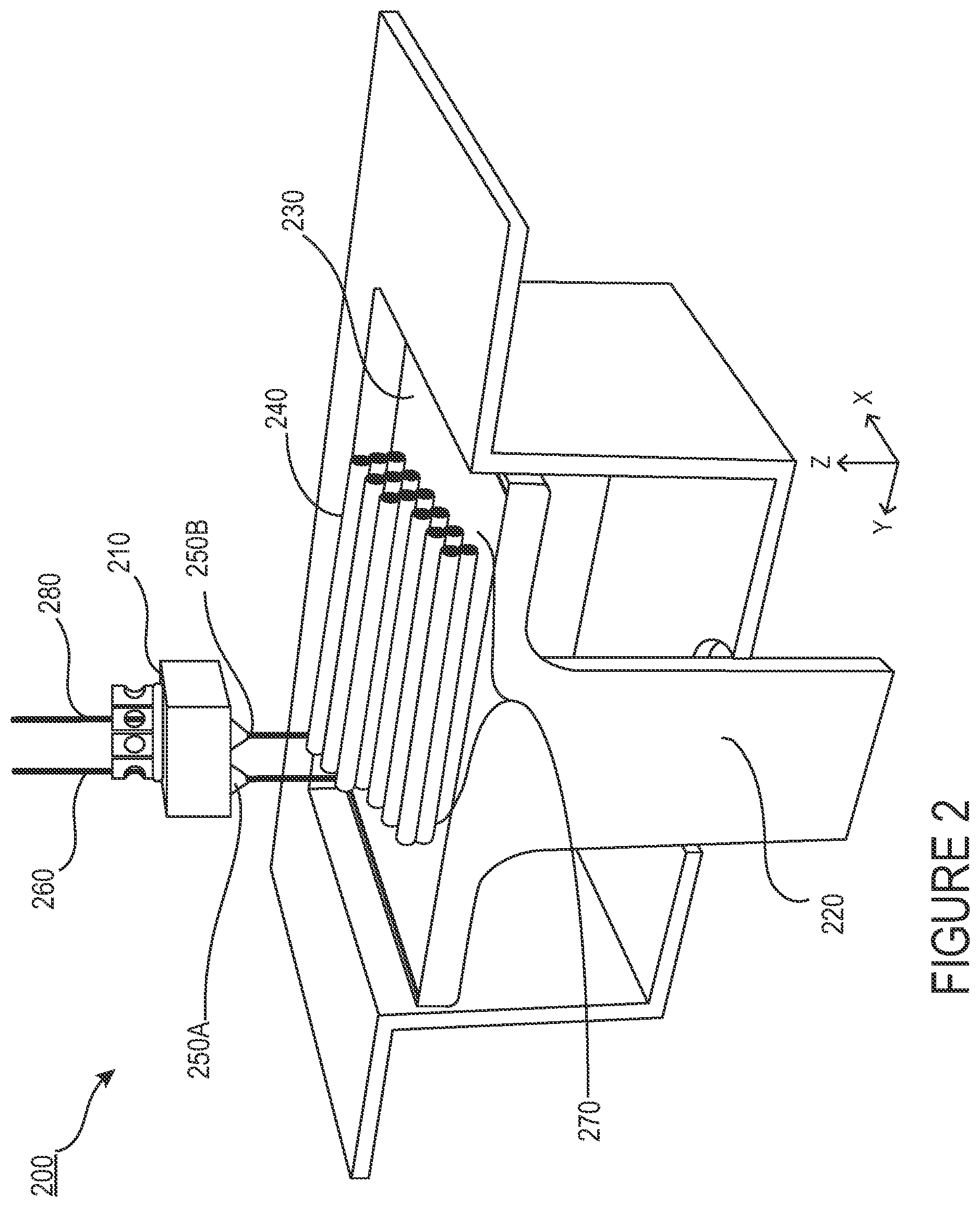
FIG. 2 is a block diagram of an exemplary 3-D printer.
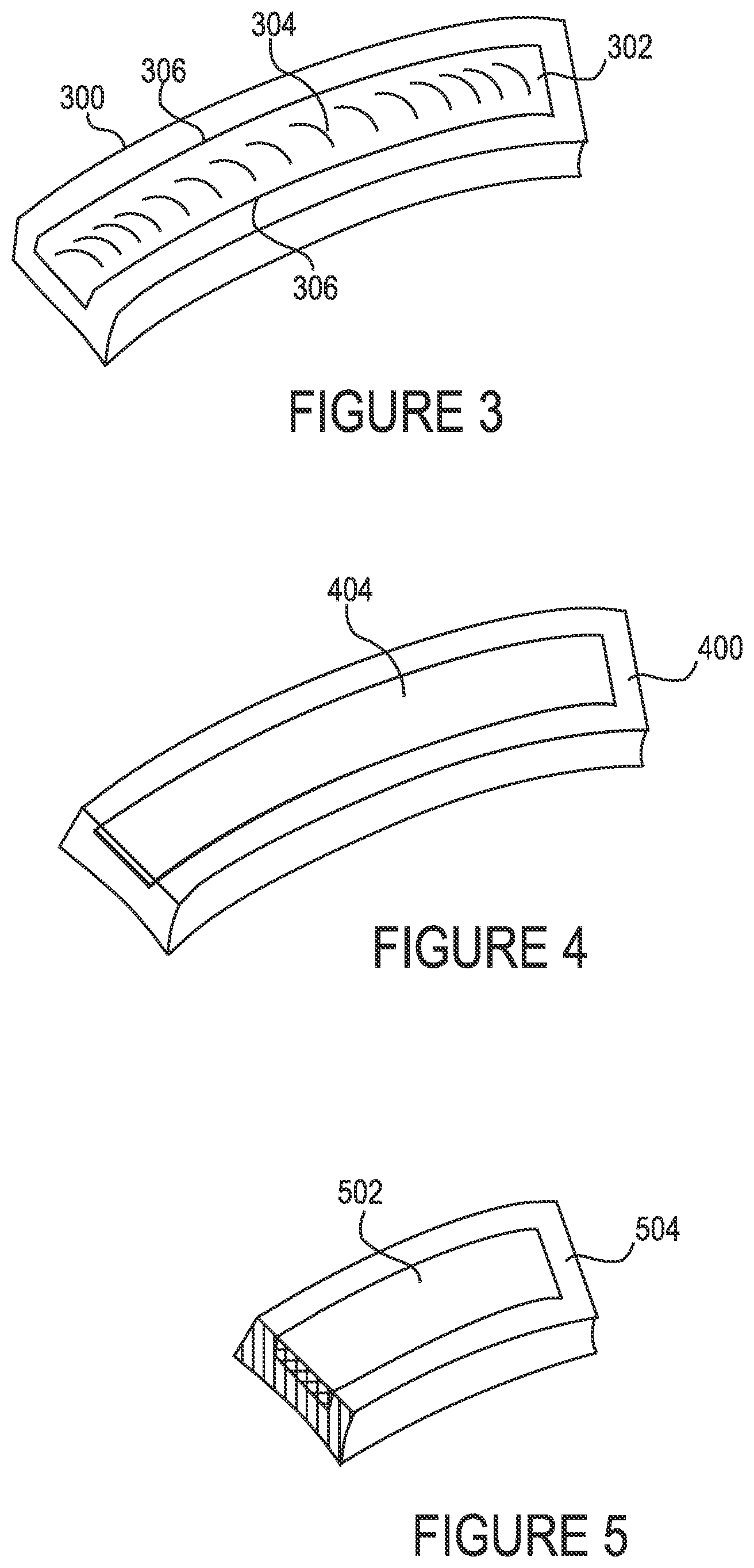
FIG. 3 shows a perspective view of a 3-D printed tooling shell
FIG. 4 shows a perspective view of 3-D printed tooling shell with CFRP inserted therein.
FIG. 5 is a cross sectional perspective view of the combined material and tooling shell.
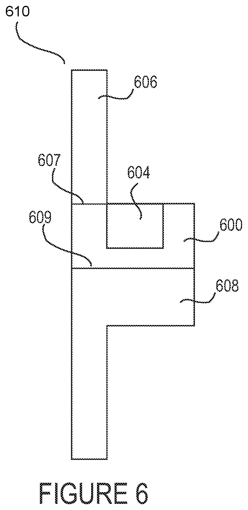
FIG. 6 shows a side view of an exemplary interior door panel 610 in a transport structure using the dual assembled component.
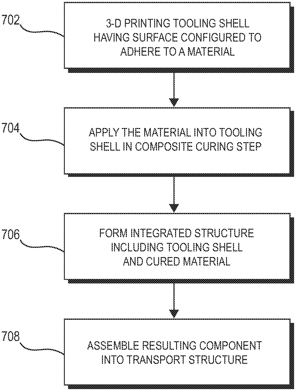
FIG. 7 is a flow diagram illustrating an exemplary process for producing a component having a composite reinforcement overlaying a tooling shell to form an integrated structure for use as a component in a transport structure.
FIG. 8 is an illustration of an integrated structure composed of an overlay of fabric composite reinforcement over additively manufactured tooling.
FIG. 9 is an illustration of an integrated structure including tooling formed with an internal lattice structure.
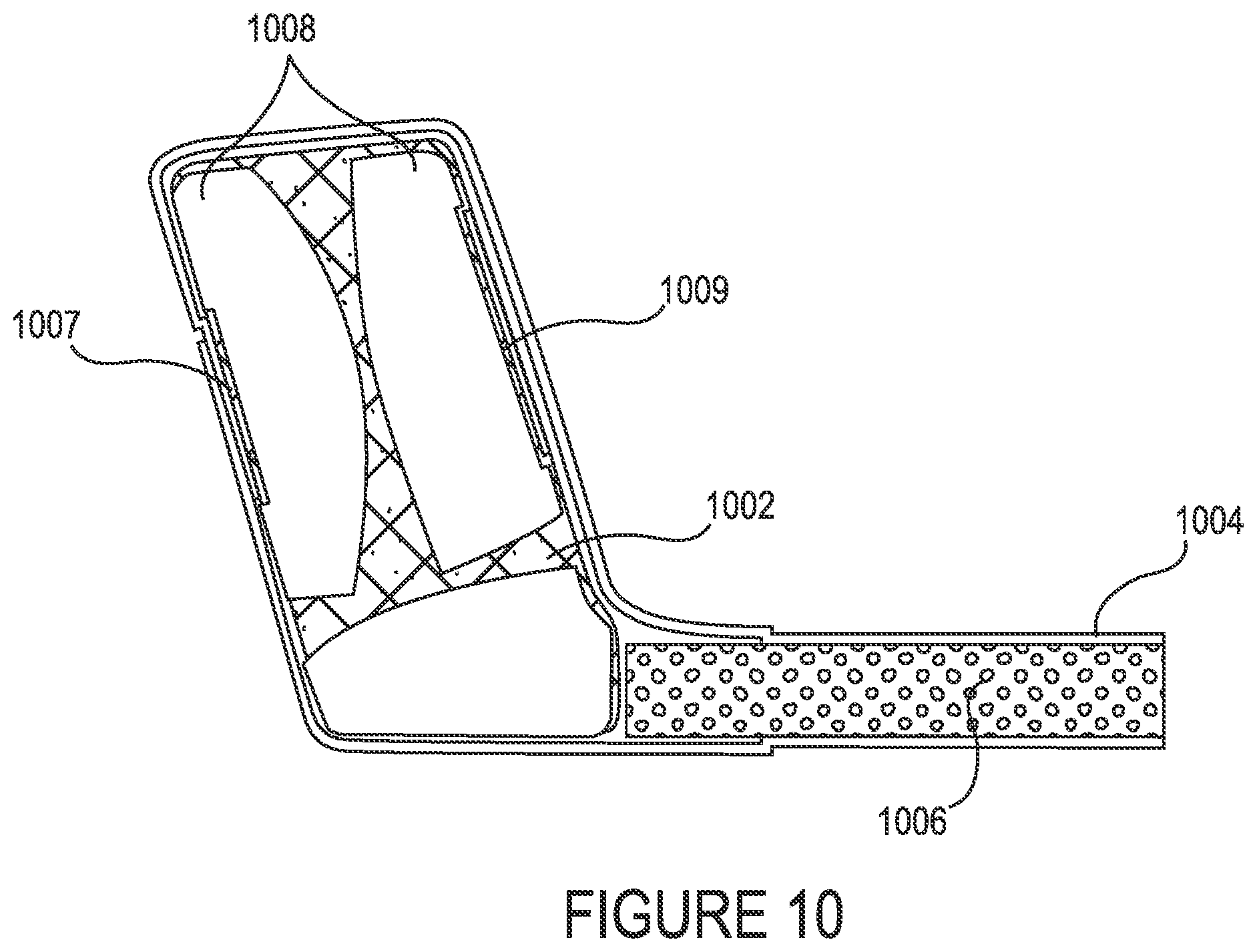
FIG. 10 is an illustration of the integrated structure having pockets and tooling with topology optimization.
FIG. 11 is an illustration of an integrated structure using co-molded nodes.
FIG. 12 is a flow diagram illustrating an exemplary process for producing a component having a composite material over a tooling shell to produce an integrated structure for use as a component in a transport structure.
FIG. 13 is an illustration of an integrated structure including composite material sandwiched between nodes and fastened via a mechanical clamp.
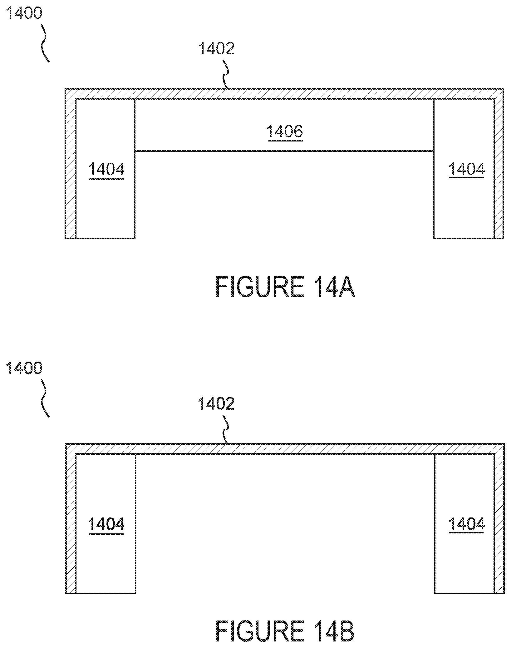
FIG. 14A-B are an example of an integrated structure using a composite skin and multi-material tools.
FIG. 15 is an example of an integrated structure using peel plies on the cured composite surface.
DETAILED DESCRIPTION
The detailed description set forth below in connection with the appended drawings is intended to provide a description of various exemplary embodiments of techniques for fabric composite reinforcement over additively manufactured tooling and is not intended to represent the only embodiments in which the invention may be practiced. The term "exemplary" used throughout this disclosure means "serving as an example, instance, or illustration," and should not necessarily be construed as preferred or advantageous over other embodiments presented in this disclosure. The detailed description includes specific details for the purpose of providing a thorough and complete disclosure that fully conveys the scope of the invention to those skilled in the art. However, the invention may be practiced without these specific details. In some instances, well-known structures and components may be shown in block diagram form, or omitted entirely, in order to avoid obscuring the various concepts presented throughout this disclosure.
The use of additive manufacturing, also known as 3-D printing, in the context of composite tooling provides significant flexibility for enabling manufacturers of mechanical structures and mechanized assemblies to manufacture parts with complex geometries. For example, 3-D printing techniques provide manufacturers with the flexibility to design and build parts having intricate internal lattice structures and/or profiles that are not possible to manufacture via traditional manufacturing processes.
FIG. 1 is a flow diagram 100 illustrating an exemplary process of initiating a process of 3-D printing. A data model of the desired 3-D object to be printed is rendered (step 110). A data model is a virtual design of the 3-D object. Thus, the data model may reflect the geometrical and structural features of the 3-D object, as well as its material composition. The data model may be created using a variety of methods, including 3D scanning, 3D modeling software, photogrammetry software, and camera imaging.
3D scanning methods for creating the data model may also use a variety of techniques for generating a 3-D model. These techniques may include, for example, time-of flight, volumetric scanning, structured light, modulated light, laser scanning, triangulation, and the like.
3-D modeling software, in turn, may include one of numerous commercially available 3-D modeling software applications. Data models may be rendered using a suitable computer-aided design (CAD) package, for example in an STL format. STL files are one example of a file format associated with commercially available CAD software. A CAD program may be used to create the data model of the 3-D object as an STL file. Thereupon, the STL file may undergo a process whereby errors in the file are identified and resolved.
Following error resolution, the data model can be "sliced" by a software application known as a slicer to thereby produce a set of instructions for 3-D printing the object, with the instructions being compatible and associated with the particular 3-D printing technology to be utilized (step 120). Numerous slicer programs are commercially available. Slicer programs convert the data model into a series of individual layers representing thin slices (e.g., 100 microns thick) of the object be printed, along with a file containing the printer-specific instructions for 3-D printing these successive individual layers to produce an actual 3-D printed representation of the data model.
A common type of file used for this purpose is a G-code file, which is a numerical control programming language that includes instructions for 3-D printing the object. The G-code file, or other file constituting the instructions, is uploaded to the 3-D printer (step 130). Because the file containing these instructions is typically configured to be operable with a specific 3-D printing process, it will be appreciated that many formats of the instruction file are possible depending on the 3-D printing technology used.
In addition to the printing instructions that dictate what and how an object is to be rendered, the appropriate physical materials necessary for use by the 3-D printer in rendering the object are loaded into the 3-D printer using any of several conventional and often printer-specific methods (step 140). In fused deposition modeling (FDM) 3-D printers, for example, materials are often loaded as filaments on spools, which are placed on one or more spool holders. The filaments are typically fed into an extruder apparatus which, in operation, heats the filament into a melted form before ejecting the material onto a build plate or other substrate, as further explained below. In selective laser sintering (SLS) printing and other methods, the materials may be loaded as powders into chambers that feed the powder to a build platform. Depending on the 3-D printer, other techniques for loading printing materials may be used.
The respective data slices of the 3-D object are then printed based on the provided instructions using the material(s) (step 150). In 3-D printers that use laser sintering, a laser scans a powder bed and melts the powder together where structure is desired, and avoids scanning areas where the sliced data indicates that nothing is to be printed. This process may be repeated thousands of times until the desired structure is formed, after which the printed part is removed from a fabricator. In fused deposition modeling, parts are printed by applying successive layers of model and support materials to a substrate. In general, any suitable 3-D printing technology may be employed for purposes of this disclosure.
FIG. 2 is a block diagram of an exemplary 3-D printer 200. While any number of 3-D printed technologies can be suitably employed, the 3-D printer 200 of FIG. 2 is discussed in the context of an FDM technique. 3-D printer 200 includes an FDM head 210 which in turn includes extrusion nozzles 250A and 250B, a moveable build stage 220, and a build plate 230 at the top of the build stage 220.
Depending on the intended composition of the structure and the need for any support material for providing support to overhanging elements of the structure that might otherwise be subject to possible gravitational deformation or collapse, a plurality of materials may be used for printing an object. One or more suitable filament materials 260 may be wound on a spool (not shown) and fed into FDM head 210. (In other technologies described above, the material may be provided as a powder or in other forms). The FDM head 210 can be moved in X-Y directions based on the received printing instructions by a numerically controlled mechanism such as a stepper motor or servo motor. The material, which may in one exemplary embodiment constitute a thermoplastic polymer, may be fed to the FDM head 210 which includes the extrusion nozzles 250A and 250B. The extruder in FDM head 210 heats the filament material 260 into a molten form, and extrusion nozzle 250a ejects the molten material and deposits it onto the build plate 230 of build stage 220.
Responsive to the received printing instructions, the FDM head 210 moves about a horizontal (X-Y) plane such that extrusion nozzle 250A drops the material 260 at the target location to form a line 240 of applied material. (The FDM head 210 may also be configured to move in the Z-direction and/or to rotate about one or more axes in certain configurations). The layer 270 of material 260, including line 240, is formed by depositing the material 260 line by line, with each line of the material 260 hardening as the material is deposited on the build plate 230. After one layer 270 is formed at the appropriate locations in the X-Y plane, the next layer may be formed in a similar way.
The build plate 230 may be a component of a controlled table moveable in at least the vertical Z direction. When rendering of a layer 270 is completed, the build stage 220 and build plate 230 may lower by an amount proportional to the thickness of layer 270 in the vertical (Z) direction so that the printer can begin application of the next layer, and so on until a plurality of cross sectional layers 240 having a desired shape and composition are created.
While a substantially rectangular structure of layers is shown for purposes of simplicity in this illustration, it will be appreciated that the actual printed structure may embody substantially any shape and configuration depending on the data model. That is, the actual shape of the rendered layers will correspond to the defined geometry of the 3D-model being printed.
In addition, as indicated above, a plurality of different materials may be used to print the object. In some instances, two different materials 260 and 280 may concurrently be applied by respective extruder nozzles 250A and 250B.
In an exemplary embodiment, a part for a transport structure is formed using an appropriately shaped and structured tooling shell to mold one or more layers of composite material. The composite material is adhered to the surface of the tooling shell to form an integrated structure that includes both the composite material and the tooling shell. The integrated structure is operable for use as a component in a transport structure such as a vehicle. In an exemplary embodiment, the tooling shell is 3-D printed, thereby eliminating the often costly and time-consuming techniques associated with the laborious machining process. In these embodiments, the tooling shell may play the dual role of molding the composite material and serving as a useful structure in conjunction with the molded material to form a component for assembly within the transport structure itself, such as a vehicle panel, joint or other component, an aircraft wing, and the like.
FIG. 3 shows a perspective view of a 3-D printed tooling shell 300. The tooling shell may include any material having appropriate or suitable characteristics for molding another material. For example, if the material to be molded using the tooling shell is carbon fiber reinforced polymer (CFRP), then an Invar alloy may be a suitable candidate for use in molding the material because its coefficient of thermal expansion is very similar to that of carbon fiber. In other cases, the tooling structure may composed of other materials, including metals, alloys and plastics. The indentation 302 in tooling shell 300 may be of a suitable volume for accommodating an appropriate amount of material to be molded. In another exemplary embodiment, an upper half of a tooling shell may be provided in order to seal the material during curing. In still other embodiments, vacuum and fluid channels may be integrated into tooling shell 300 in order to enable resin material to be provided to indentation 302 to facilitate the process of fabricating the material. In other embodiments, because the tooling shell 300 may ultimately serve as a structural part in addition to a mold, the choice of materials out of which tooling shell 300 can be made may also be limited by the types of materials that are appropriate for the final component as assembled into the transport structure.
In one embodiment, the adhesive to be used for CRFP and the metal 3-D printed mold can be the matrix material of the CFRP itself
Further included in FIG. 3 are small surface indentations 304 that had been 3-D printed into the material. Because the tooling shell 302 and the material to be molded can ultimately form a single component for assembly into a transport structure, it may be desirable in some embodiments to provide a mechanism to cause the component to adhere to the interior 302 of the tooling shell 300. The purpose of the small surface indentations 304 are to assist in providing surface adhesion between the inner portion of tooling shell 300 and the material to be molded in tooling shell 300. In other embodiments, surface indentations may also be formed on the inner side walls 306 of the tooling shell to further facilitate the surface adhesion process. In alternative embodiments, other means may be used to assist in surface adhesion. For example, a resin may be applied to inner surface 302 prior to insertion of the materials to be molded. Alternatively, clamps, screws, nuts and bolts, nails, thermal fusion, etc. may be used to secure the composite material to the tooling shell.
FIG. 4 shows a perspective view of 3-D printed tooling shell 400 with CFRP inserted therein. As noted above, a geometry 404 of a structure to be molded within the tooling shell 400 may be designed to conform to the shape of an inner surface of the tooling shell 400, depending on how the mold is configured. In this manner, the tooling shell acts as a section of a mold to shape the composite material that will be cured into the a portion of the component, as described further below.
A composite fabrication process including a composite layup may be performed using the tooling shell 400. In this example, carbon fiber material (or another suitable material) may be applied via a layup process on inner surface of the tooling shell 400 as a first step in producing the component. The carbon fiber material may be laid over the tooling shell 400, compressed and cured.
FIG. 5 is a cross sectional perspective view 500 of the combined material 502 and tooling shell 504. The difference in shading between material 502 and tooling shell 504 shows that the two structures in this particular embodiment have a different material composition, although such a feature need not be necessary in certain embodiments.
FIG. 6 shows a side view of an exemplary interior door panel 610 in a transport structure using the dual assembled component 600. In this embodiment, the door panel includes a first component 606 and a second component 608, either of which may be molded or 3-D printed. In this exemplary embodiment, first component 606 is adhered via any available means to a surface 607 of the component 600 described in FIGS. 3-5. Second component 608 is adhered via any available means to a surface 609 of the component of FIG. 4 (i.e., the unseen bottom portion of the component in FIG. 4). The interior panel 610 can thereupon be used in a transport structure with the carbon fiber material 604 appropriately placed. It should be understood that the integration of the component with an interior door panel is purely for illustrative purposes, and the component of FIG. 4 can be used in a wide number of practical applications in various portions of a transport structure.
In one exemplary embodiment, a layup uses pre-impregnated ("prepreg") carbon fiber plies that are delivered onto the tooling shell 400 (FIG. 4) with the resin matrix applied. The prepreg technique provides effective resin penetration and assists in ensuring substantially uniform dispersion of the resin. The prepreg plies may be applied onto the tooling shell 400 to form a laminate stack.
In another embodiment, a dry lay-up uses dry woven fiber sheets. Resin may thereupon be applied to the dry plies after layup is complete, such as by resin infusion. In an alternative exemplary embodiment, wet layup may be used wherein each ply may be coated with resin and compacted after being placed.
As indicated above, a top shell or a seal for the mold may be 3-D printed and applied over tooling shell 400 to provide a means to mold the structure 502 (FIG. 5), for example, into the geometry 404 of the inner part of the tooling shell 400 (FIG. 4). Upon completion of the molding process, the carbon fiber material may, for example, be vacuum compacted and baked in an oven for a designated time period.
The specific molding and resin infusion processes used during these stages may vary depending on variables such as molding techniques, design constraints, and desired manufacturing yield. Generally, the 3-D-printed tooling shell may be used in connection with a variety of composite manufacturing techniques including, for example, Resin Transfer Molding (RTM), hand layup, prepregs, sheet molding, and Vacuum Assisted Resin Transfer Molding (VARTM).
FIG. 7 shows an exemplary flow diagram of a method for creating a component for use in a transport structure. At 702, a tooling shell is 3-D printed using a geometry that can ultimately enable it to be used as part of an integrated structure for further within another structure such as a vehicle panel. The tooling shell may be designed for potential adherence to a material to be subsequently used. At 704, the material, such as CFRP or another composite fabric, is applied and a composite fabrication process is used to mold and harden the material. At 706, when the composite fabrication is complete, the material adheres to the tooling shell and a resulting component is formed which includes an integrated structure composed of the cured material and the tooling shell. At 708, the integrated structure is assembled as a component into a transport structure.
In another exemplary embodiment, a 3-D printed plastic frame is first used as a template for composite tooling. On completion of the cure of the composite material, the resulting assembly may then be used as a frame or other component for a transport structure. FIG. 8 is an illustration of a structure composed of an overlay of fabric composite reinforcement over additively manufactured tooling. The 3-D printing technology selection may be driven by the materials requirement and by the speed of the printing process. A 3-D printed plastic frame 802 is formed. Advantageously, plastic printing processes are typically 25-50 times faster than metal printing processes. A further benefit in using additively manufactured plastic tooling is the ability to obtain larger parts because the build chambers of plastic 3-D printers are typically much larger than those of metal 3-D printers. Additionally, the plastic 3-D printers can in many cases print much smoother surfaces. In an embodiment, the material used is Acrylonitrile Butadiene Styrene (ABS), a common thermoplastic polymer. However, any number of suitable materials may be used depending on the application and the properties of the materials needed.
Further, in the embodiment shown, a CNC foam core 806 is additively manufactured and coupled to plastic frame 802 using an adhesive or other available means. In one embodiment, the frame 802 and core 806 are co-printed in a single rendering. The foam core may be composed of the same material as plastic frame 802. In another embodiment, a honeycomb panel configuration is used in place of foam core. It will be appreciated that the illustrated embodiment in FIG. 8 is exemplary in nature as a number of materials and shapes may alternatively be used for purposes of this disclosure.
A variety of fiber composite fabrics may be used in the subsequent composite fabrication process, depending on strength requirements and other factors. Some examples of possible materials include glass fiber, carbon fiber, Kevlar, and the like. In the embodiment shown, glass fiber prepregs 804 are draped over the additively manufactured tooling. The glass fiber pregreg layer 804 may include, in one exemplary embodiment, a fiber reinforced polymer (FRP) skin (E Glass). Other composites, including carbon fiber, may be used as well. Layup is performed on the FRP. After the material is cured, the integrated structure composed of the ABS tooling with frame 802 and foam core 806 and the overlaid glass fiber composite 804 may then be used as a component in a transport structure.
For added weight savings and/or for improved load bearing capabilities, depending on the application and intended use of the integrated structure, the 3-D printed tooling may include a structure that uses an optimized topology. FIG. 9 shows an illustration of an integrated structure including tooling formed with an internal lattice structure. Plastic tooling 902 includes a lattice structure designed for the loads to which it will be subject when it is assembled as a component. The foam core or honeycomb panel structure 906 is included, with the layers of glass fiber reinforced polymer 904 overlaid on the tooling structure. One advantage of this structure includes the savings in plastic material achieved via use of the lattice.
In another exemplary embodiment, the tooling may be additively manufactured with pockets for a flush finish. FIG. 10 is an illustration with the integrated structure having pockets and tooling with topology optimization. As seen in FIG. 10, tooling component 1002 is 3-D printed with pockets 1007, 1009 and hollow sections 1008. The pocket 1007 enables the end areas of the glass fiber material surrounding the tooling to have a flush finish. The structure further includes a component 1006 with a honeycomb or foam filling. In addition, to provide reinforcement of one of the pockets 1007, 1009 where mechanical reinforcement is desirable or necessary, CFRP or another composite material may be used to provide local reinforcement for the pockets. As before, prepreg layers of GFRP (or another suitable composite) may be overlaid and cured over the tooling to produce the integrated structure.
In some embodiments, mechanical clamping may be desirable to secure the composite materials in place. FIG. 11 is an illustration of an integrated structure using co-molded nodes. As in previous embodiments, tooling shell 1102 is additively manufactured using ABS or another suitable material. FRP or another suitable material 1104 is inlaid and cured over the tooling shell. A 3-D printed inner node 1114 is co-printed with the tooling or printed separately and added to secure a first side of portions 1120 of the composite material 1104. Likewise, a 3-D printed outer node 1112 is inserted over a second side of portions 1120 of the composite material. The composite material is therefore clamped and secured to the tooling shell, and the entire integrated structure may be used as a component in a transport structure. In one exemplary embodiment, the nodes are co-printed using aluminum to ensure strength. Other materials, however, may be equally suitable.
In an exemplary embodiment, AM metal nodes can be implemented as suspension pick-up points or interfaces for the crush rails associated with the overall transport structure. Crush rails are energy absorbing rail structures that may be implemented on a vehicle to enable the vehicle to absorb energy from an impact in a controlled and directed manner. The rails may be sandwiched between the metal nodes, which in turn may be attached to the vehicle suspension. An example of such an arrangement is shown in FIG. 13. In another embodiment, mechanical clamping can be used in connection with vacuum connectors to cure a composite layup.
FIG. 13 is an illustration of an integrated structure 1300 including composite material sandwiched between nodes and fastened via a mechanical clamp. The structure 1300 includes upper and lower aluminum nodes 1302a-b, which may be additively manufactured. Beneath node 1302b is tooling shell 1308, which may be additively manufactured using FDM or another suitable technology. In an embodiment, tooling shell 1308 is composed of ABS or a thermoplastic such as ULTEM (polyetherimide).
Laid over tooling shell 1308 are two composite skin layers 1306a and 1306b which may be composed of GFRP. Near their end, GFRP layers 1306a and 1306b contact with nodes 1302a-b. GFRP layers 1306a and 1306b may be cured on top of both of the AL node 1302b and the FDM tooling shell 1308. GFRP layers 1306a-b may then be clamped by nodes 1302a, which may be placed on top of GFRP layers 1306a and 1306b.
To secure the clamping of layers 1306a and 1306b, a feature 1304 for mechanical fastening may be employed. The feature 1304 in this embodiment is a large opening in which a bolt or other fastener can be inserted. The fastener can provide a force to secure the layers 1306a and b, such as by using a standard threaded bolt, a nut-bolt combination or any other suitable mechanical fastening or clamping mechanism. In other embodiments, the clamping feature may be different than the aperture 1304 and may include other types of fasteners or openings to accommodate fasteners.
Also shown in FIG. 13 is a protrusion 1310 from the node 1302b. The protrusion includes an aperture that is configured to "snap fit" into another protrusion 1312, which may be a protrusion from the FDM tooling shell 1308. In an embodiment, the protrusion 1312 is a gradual protrusion jutting out of a longer FDM member (hidden from view by node 1320b) arranged in the vertical direction, with the larger protrusion 1312 at the end. The AL node 1302b may contact and press against the longer FDM member. As the AL node 1302b is moved downward relative to the longer FDM member, the pressure or force causes the larger FDM protrusion 1312 to snap into place. In an embodiment, protrusion 1312 may be affixed to a vehicle suspension system, thereby fastening structure 1300 to the suspension system. These techniques enable the aluminum clamping mechanism to interface with the FDM tool.
FIG. 12 is a flow diagram illustrating an exemplary process for producing a component having a composite material over a tooling shell to produce an integrated structure for use as a component in a transport structure. At 1202, a plastic tooling shell such as an ABS shell is additively manufactured using a suitable 3-D printer, such as an FDM 3-D printer. Thereupon, at 1204, a foam core or honeycomb panel is 3-D printed, and aluminum nodes are also 3-D printed. In one embodiment, of the three structures additively manufactured in collective steps 1202, 1204, two or more of the structures are co-printed. It should be noted that different materials may be used than the materials identified, depending on the embodiment and objectives.
At 1206, the tooling shell is coupled to or adjoined with the foam core. In some embodiments where the two components are additively manufactured as a single unit, this step may be unnecessary. In other embodiments, an appropriate adhesive, screw, clamp or other connection means may be used.
At 1208, the appropriate material, such as GFRP, is inlaid over the tooling shell and is prepared and cured in a composite fabrication process. In some embodiments, the tooling shell and foam core have an adhesive means to adhere to the composite. In other embodiments, other adherence mechanisms may be used. At 1210, for example, the aluminum nodes printed at 1204 may be used to clamp the composite material to the tooling shell in a manner described above with respect to FIG. 11.
Thereupon, at 1212, the resulting integrated structure may be used as a component in a transport structure. In some embodiments discussed above, the structure may use a lattice or other mechanical arrangement, such as a CFRP layer, to provide additional support depending on the stresses to which the structure may be subject. The tooling shell can be optimized and printed with pockets for placing additional reinforcement where needed. In an embodiment, GFRP is overlaid with the tooling structure, but CFRP is used in pockets on the tooling shell to optimize load path for load transfer. These configurations may also enable use of unidirectional reinforcement in the pockets/features on the tooling shell as well as woven reinforcement (unidirectional has fibers in one direction while woven has fibers running in the 0 and 90 degree angles). In transport structures and other wheeled vehicles, load transfer is the change of load sustained by the different wheels during the processes of longitudinal and lateral acceleration, which includes braking and deceleration. Other types of loads may also be involved in transport structures and mechanized assemblies. A shear load is a force that causes shear stress when applied to a structural element. Reinforcement using composite fiber materials, lattices, and other structures may be necessary in cases where load the transfer mechanics of a part, including the expected shear loads, dictates it.
In other embodiments, multi-material tools may be used. For example, certain sections of the tooling may be printed with a dissolvable material. Once the composite is overlaid and cured, these sections may be dissolved. This technique may be ideal for weight saving mechanisms and in designs where only the composite shell is needed. In the case where only composite skin is needed in a certain section, multi-material tools may be used. In an embodiment, release mechanisms (release agents, tooling surface preparation, etc.) may be used to enable certain sections of the tooling to come out or become available after the composite has cured to achieve sections with just composite skin.
FIG. 14A-B are an example of an integrated structure 1400 using a composite skin and multi-material tools. Referring to FIG. 14A, a multi-material tooling shell including components 1404 and 1406 may be additively manufactured. Here, unlike component 1404 which may be an ordinary thermoplastic or other suitable material rendered using FDM (or in some cases it may be a metallic material rendered using some other AM technology), component 1406 may constitute a known dissolvable material. A skin or material 1402 such as GFRP or CFRP is laid up over the tooling shell as discussed above. It is desired that the final integrated structure include components 1404 and 1402. However, component 1406 is used merely for molding purposes to shape and stabilize material 1402 and to allow it to cure. Accordingly after material 1402 is cured, component 1406 may be dissolved away using techniques conventionally known to produce the final integrated structure 1400 in FIG. 14b. Using these multi-material techniques in conjunction with the methods disclosed herein, an increasingly wide variety of structures may be produced.
In another aspect of the disclosure, peel plies can be disposed on the surface of the cured composite to improve adhesive bonding. FIG. 15 is an example of an integrated structure 1500 including a composite 1514 such as GFRP, CFRP, or the like. As in prior embodiments, an additively manufactured tool 1516 is used to mold the composite 1514 during a layup process as well as to be a part of the structure being built. To improve the bonding between the cured composite 1514 and the 3-D Printed tool 1516, a layer of a material with chemically suitable properties, such as peel ply 1512, can be arranged between the tool 1516 and the composite 1514. To enable an accurate result in some embodiments, another layer of peel ply 1512 may be inserted over the composite 1514. Between the upper peel ply layer 1512 and a bagging film 1508 is breather 1510. Bagging film 1508 may include thru-bag vacuum connector for creating negative pressure. Sealant 1502 may be used to seal the bagging film 1508, and a flash tape 1504 may be used to secure the peel ply 1512 to the composite 1514.
On completion of the cure, the nature of the peel ply 1512 enables the cured composite 1514 to be removed from the tool 1516. The peel ply 1512 may leave a certain texture on the surface of the cured composite 1514 that is conducive to adhesive bonding. After discarding the peel ply 1512, adhesive can be applied between the tool--composite interface to thereby form a strong bond between the tool 1516 and composite 1514.
The previous description is provided to enable any person skilled in the art to practice the various aspects described herein. Various modifications to these exemplary embodiments presented throughout this disclosure will be readily apparent to those skilled in the art, and the concepts disclosed herein may be applied to other techniques for composite inlay of materials. Thus, the claims are not intended to be limited to the exemplary embodiments presented throughout the disclosure, but are to be accorded the full scope consistent with the language claims. All structural and functional equivalents to the elements of the exemplary embodiments described throughout this disclosure that are known or later come to be known to those of ordinary skill in the art are intended to be encompassed by the claims. Moreover, nothing disclosed herein is intended to be dedicated to the public regardless of whether such disclosure is explicitly recited in the claims. No claim element is to be construed under the provisions of 35 U.S.C. .sctn. 112(f), or analogous law in applicable jurisdictions, unless the element is expressly recited using the phrase "means for" or, in the case of a method claim, the element is recited using the phrase "step for."
* * * * *
D00000
D00001
D00002
D00003
D00004
D00005
D00006
D00007
D00008
D00009
D00010
D00011
D00012
D00013

XML
uspto.report is an independent third-party trademark research tool that is not affiliated, endorsed, or sponsored by the United States Patent and Trademark Office (USPTO) or any other governmental organization. The information provided by uspto.report is based on publicly available data at the time of writing and is intended for informational purposes only.
While we strive to provide accurate and up-to-date information, we do not guarantee the accuracy, completeness, reliability, or suitability of the information displayed on this site. The use of this site is at your own risk. Any reliance you place on such information is therefore strictly at your own risk.
All official trademark data, including owner information, should be verified by visiting the official USPTO website at www.uspto.gov. This site is not intended to replace professional legal advice and should not be used as a substitute for consulting with a legal professional who is knowledgeable about trademark law.