Device for laser-inducing cavitation strengthening with multi-system automatic coordination work
Ren , et al. October 27, 2
U.S. patent number 10,814,431 [Application Number 15/326,361] was granted by the patent office on 2020-10-27 for device for laser-inducing cavitation strengthening with multi-system automatic coordination work. This patent grant is currently assigned to JIANGSU UNIVERSITY. The grantee listed for this patent is JIANGSU UNIVERSITY. Invention is credited to Hao He, Jiaxing Lu, Xudong Ren, Yanqun Tong, Deshun Wang, Jie Wang, Kun Wu, Shouqi Yuan, Rui Zhou, Chengya Zuo.
| United States Patent | 10,814,431 |
| Ren , et al. | October 27, 2020 |
Device for laser-inducing cavitation strengthening with multi-system automatic coordination work
Abstract
A device and a method for laser-inducing cavitation strengthening with multi-system automatic coordination work. The device comprises a plurality of systems, including a clamping system, a lifting system, an imaging system, a computer control system, a laser system and an energy density amplifying system, etc. The device for laser-inducing cavitation strengthening comprises a laser cavitation device and a fixing platform.
| Inventors: | Ren; Xudong (Jiangsu, CN), Yuan; Shouqi (Jiangsu, CN), Zuo; Chengya (Jiangsu, CN), Tong; Yanqun (Jiangsu, CN), Wang; Deshun (Jiangsu, CN), Wu; Kun (Jiangsu, CN), Lu; Jiaxing (Jiangsu, CN), He; Hao (Jiangsu, CN), Zhou; Rui (Jiangsu, CN), Wang; Jie (Jiangsu, CN) | ||||||||||
|---|---|---|---|---|---|---|---|---|---|---|---|
| Applicant: |
|
||||||||||
| Assignee: | JIANGSU UNIVERSITY (Jiangsu,
CN) |
||||||||||
| Family ID: | 1000005140284 | ||||||||||
| Appl. No.: | 15/326,361 | ||||||||||
| Filed: | April 30, 2015 | ||||||||||
| PCT Filed: | April 30, 2015 | ||||||||||
| PCT No.: | PCT/CN2015/077904 | ||||||||||
| 371(c)(1),(2),(4) Date: | January 13, 2017 | ||||||||||
| PCT Pub. No.: | WO2016/155069 | ||||||||||
| PCT Pub. Date: | October 06, 2016 |
Prior Publication Data
| Document Identifier | Publication Date | |
|---|---|---|
| US 20170203385 A1 | Jul 20, 2017 | |
Foreign Application Priority Data
| Mar 30, 2015 [CN] | 2015 1 0141582 | |||
| Current U.S. Class: | 1/1 |
| Current CPC Class: | G01N 29/2418 (20130101); G01N 21/1717 (20130101); B23K 26/352 (20151001); C21D 10/005 (20130101); B23K 26/1224 (20151001); G01N 21/84 (20130101); G01N 29/02 (20130101); G01N 2291/0228 (20130101) |
| Current International Class: | B23K 26/00 (20140101); G01N 21/84 (20060101); C21D 10/00 (20060101); G01N 29/02 (20060101); B23K 26/352 (20140101); G01N 29/24 (20060101); G01N 21/17 (20060101); B23K 26/12 (20140101) |
| Field of Search: | ;219/121.85 |
References Cited [Referenced By]
U.S. Patent Documents
| 3588737 | June 1971 | Chow |
| 3836950 | September 1974 | Bhuta |
| 4492843 | January 1985 | Miller |
| 4501949 | February 1985 | Antol |
| 4541055 | September 1985 | Wolfe |
| 4555610 | November 1985 | Polad |
| 4876690 | October 1989 | Nishida |
| 4904340 | February 1990 | Miracky |
| 4986655 | January 1991 | Sweeney |
| 4986656 | January 1991 | Sweeney |
| 5012069 | April 1991 | Arai |
| 5037431 | August 1991 | Summers |
| 5053602 | October 1991 | Aharon |
| 5057184 | October 1991 | Gupta |
| 5142120 | August 1992 | Hanson |
| 5201989 | April 1993 | Douglas |
| 5238529 | August 1993 | Douglas |
| 5238530 | August 1993 | Douglas |
| 5279703 | January 1994 | Haberger |
| 5312516 | May 1994 | Douglas |
| 5374330 | December 1994 | Douglas |
| 5486264 | January 1996 | Ghandour |
| 5504719 | April 1996 | Jacobs |
| 5526110 | June 1996 | Braymen |
| 5560843 | October 1996 | Koike |
| 5566075 | October 1996 | Syouji |
| 5567336 | October 1996 | Tatah |
| 5593606 | January 1997 | Owen |
| 5631425 | May 1997 | Wang |
| 5683601 | November 1997 | Tatah |
| 5749830 | May 1998 | Kaneko |
| 5751416 | May 1998 | Singh |
| 5814784 | September 1998 | Kinsman |
| 5874708 | February 1999 | Kinsman |
| 5889587 | March 1999 | D'Silva |
| 5900171 | May 1999 | Karube |
| 5910261 | June 1999 | Mori |
| 5935462 | August 1999 | Tatah |
| 5947051 | September 1999 | Geiger |
| 5956253 | September 1999 | Gottschalk |
| 5982535 | November 1999 | Inoue |
| 6029912 | February 2000 | Woolley |
| 6037564 | March 2000 | Tatah |
| 6041020 | March 2000 | Caron |
| 6043452 | March 2000 | Bestenlehrer |
| 6060127 | May 2000 | Tatah |
| 6144007 | November 2000 | Levin |
| 6163012 | December 2000 | Kimura |
| 6180912 | January 2001 | Tatah |
| 6211080 | April 2001 | Tatah |
| 6232738 | May 2001 | Sawada |
| 6284999 | September 2001 | Virtanen |
| 6295719 | October 2001 | Strom |
| 6300592 | October 2001 | Ulrich |
| 6326586 | December 2001 | Heyerick |
| 6376798 | April 2002 | Remue |
| 6430465 | August 2002 | Cutler |
| 6487229 | November 2002 | Govorkov |
| 6566626 | May 2003 | Gaissinsky |
| 6583383 | June 2003 | Higashi |
| 6588738 | July 2003 | Sukuvaara |
| 6621838 | September 2003 | Naito |
| 6622058 | September 2003 | Picard |
| 6653971 | November 2003 | Guice |
| 6667796 | December 2003 | Nishi |
| 6720522 | April 2004 | Ikegami |
| 6730447 | May 2004 | Ito |
| 6731570 | May 2004 | Langdon |
| 6746967 | June 2004 | Brask |
| 6770568 | August 2004 | Brask |
| 6772040 | August 2004 | Picard |
| 6777642 | August 2004 | Song |
| 6795456 | September 2004 | Scaggs |
| 6835319 | December 2004 | Song |
| 6862936 | March 2005 | Kenderian |
| 6869889 | March 2005 | Brask |
| 6870130 | March 2005 | Yamazaki |
| 6932914 | August 2005 | LeClair |
| 6940037 | September 2005 | Kovacevic |
| 6945114 | September 2005 | Kenderian |
| 6960307 | November 2005 | LeClair |
| 6995334 | February 2006 | Kovacevic |
| 7020539 | March 2006 | Kovacevic |
| 7045738 | May 2006 | Kovacevic |
| 7100846 | September 2006 | Pein |
| 7356240 | April 2008 | Adachi |
| 7532652 | May 2009 | Vetrovec |
| 7557917 | July 2009 | Beesley |
| 7605063 | October 2009 | Chebi |
| 7757561 | July 2010 | Laugharn, Jr. |
| 7969570 | June 2011 | Ebstein |
| 8016940 | September 2011 | Adachi |
| 8101921 | January 2012 | Oshemkov |
| 8115936 | February 2012 | Ochiai |
| 8125704 | February 2012 | Mielke |
| 8139910 | March 2012 | Stadler |
| 8184284 | May 2012 | Ebstein |
| 8189971 | May 2012 | Vaissie |
| 8288680 | October 2012 | Burrowes |
| 8398622 | March 2013 | Stoltz |
| 8449787 | May 2013 | Imada |
| 8458871 | June 2013 | Messina |
| 8496799 | July 2013 | Von Gutfeld |
| 8507828 | August 2013 | Krause |
| 8529738 | September 2013 | Von Gutfeld |
| 8619357 | December 2013 | Gaudiosi |
| 8628831 | January 2014 | Tang |
| 8929406 | January 2015 | Chuang |
| 8985050 | March 2015 | Von Gutfeld |
| 9022037 | May 2015 | Delfyett |
| 9042006 | May 2015 | Armstrong |
| 9089928 | July 2015 | Zediker |
| 9102008 | August 2015 | Haight |
| 9144882 | September 2015 | Lindsay |
| 9395715 | July 2016 | Brandt |
| 9436012 | September 2016 | Dvorkin |
| 9452495 | September 2016 | Hashimoto |
| 9529182 | December 2016 | Chuang |
| 9583225 | February 2017 | Uehara |
| 9608399 | March 2017 | Chuang |
| 9643273 | May 2017 | Adams |
| 9804101 | October 2017 | Deng |
| 10329641 | June 2019 | Nomura |
| 2001/0018312 | August 2001 | Gottschalk |
| 2002/0122525 | September 2002 | Rosenberger |
| 2002/0148820 | October 2002 | Tomlinson |
| 2003/0034093 | February 2003 | Morris |
| 2003/0192865 | October 2003 | Cole, III |
| 2003/0204283 | October 2003 | Picard |
| 2003/0222065 | December 2003 | Leibinger |
| 2004/0004055 | January 2004 | Barros |
| 2004/0040379 | March 2004 | O'Donnell |
| 2004/0262274 | December 2004 | Patel |
| 2005/0003737 | January 2005 | Montierth |
| 2005/0040146 | February 2005 | Takami |
| 2005/0064137 | March 2005 | Hunt |
| 2005/0123445 | June 2005 | Blecka |
| 2005/0199596 | September 2005 | Takami |
| 2005/0220675 | October 2005 | Reed |
| 2005/0221358 | October 2005 | Carrillo |
| 2005/0225751 | October 2005 | Sandell |
| 2005/0226771 | October 2005 | Lehto |
| 2005/0226779 | October 2005 | Oldham |
| 2005/0226780 | October 2005 | Sandell |
| 2005/0226782 | October 2005 | Reed |
| 2005/0231723 | October 2005 | Blasenheim |
| 2005/0232818 | October 2005 | Sandell |
| 2005/0232820 | October 2005 | Reed |
| 2005/0232821 | October 2005 | Carrillo |
| 2005/0232822 | October 2005 | Reed |
| 2005/0233363 | October 2005 | Harding |
| 2005/0233472 | October 2005 | Kao |
| 2005/0237528 | October 2005 | Oldham |
| 2005/0244932 | November 2005 | Harding |
| 2005/0263505 | December 2005 | Yamazaki |
| 2005/0280811 | December 2005 | Sandell |
| 2006/0011305 | January 2006 | Sandell |
| 2006/0013984 | January 2006 | Sandell |
| 2006/0024690 | February 2006 | Kao |
| 2006/0024831 | February 2006 | Kao |
| 2006/0029525 | February 2006 | Laugharn, Jr. |
| 2006/0029948 | February 2006 | Lim |
| 2006/0078012 | April 2006 | Miwa |
| 2006/0171656 | August 2006 | Adachi |
| 2007/0014694 | January 2007 | Beard |
| 2007/0015289 | January 2007 | Kao |
| 2007/0053795 | March 2007 | Laugharn, Jr. |
| 2007/0076077 | April 2007 | Miura |
| 2007/0157730 | July 2007 | Ochiai |
| 2007/0278719 | December 2007 | Adachi |
| 2008/0110011 | May 2008 | Reed |
| 2008/0230717 | September 2008 | Ashkenazi |
| 2009/0068062 | March 2009 | Jafari |
| 2009/0130016 | May 2009 | Mills |
| 2009/0142257 | June 2009 | Mills |
| 2009/0240368 | September 2009 | Young, Jr. |
| 2010/0031487 | February 2010 | Messina |
| 2010/0035371 | February 2010 | Yamazaki |
| 2010/0108648 | May 2010 | Koseki |
| 2010/0268042 | October 2010 | Wang |
| 2011/0036991 | February 2011 | Oshemkov |
| 2011/0048135 | March 2011 | Caron |
| 2011/0095198 | April 2011 | Smiljanic |
| 2012/0044488 | February 2012 | Senac |
| 2012/0097653 | April 2012 | Yabe |
| 2012/0113430 | May 2012 | Liu |
| 2012/0118052 | May 2012 | O'Donnell |
| 2012/0205349 | August 2012 | Uehara |
| 2012/0320368 | December 2012 | Jiao |
| 2013/0062323 | March 2013 | Hassan |
| 2013/0160557 | June 2013 | Nakajima |
| 2013/0180969 | July 2013 | Cheng |
| 2013/0259903 | October 2013 | Mortenson |
| 2014/0033821 | February 2014 | Sun |
| 2015/0269603 | September 2015 | Young, Jr. |
| 2015/0332071 | November 2015 | Hoffa |
| 2015/0355444 | December 2015 | Jiang |
| 2015/0371129 | December 2015 | Hoffa |
| 2016/0059363 | March 2016 | Ardisson |
| 2016/0221108 | August 2016 | Hoffa |
| 2017/0203385 | July 2017 | Ren |
| 103712723 | Apr 2014 | CN | |||
| 103849757 | Jun 2014 | CN | |||
| 103920884 | Jul 2014 | CN | |||
| 104561516 | Apr 2015 | CN | |||
Other References
|
International Search Report issued in PCT/CN2015/077904, dated Jan. 11, 2016. cited by applicant . Xie et al., "New progress in research and application of laser induced cavitation," Chinese Journal of Lasers, vol. 2013, No. 8 (2013). cited by applicant. |
Primary Examiner: Stapleton; Eric S
Attorney, Agent or Firm: Heslin Rothenberg Farley & Mesiti, PC
Claims
The invention claimed is:
1. A multi-system automatic coordinating apparatus for laser induced cavitation strengthening, comprising: a laser cavitation device and a fixing station, wherein the fixing station has a water tank with a cushion block inside, a temperature sensor on a side wall of the water tank, and the temperature sensor is connected to a computer; and wherein the fixing station is on a lifting system and the lifting system is on a two-axis platform, a laser emitted from the laser cavitation device passes through a wall of the water tank and focuses in the tank, and further comprising a guide rod at the upper end of the fixing station and a movable plate mounted on the guide rod, wherein the movable plate is connected with the guide rod in the form of a moving pair, the movable plate is connected to a piston rod of a cylinder, and the cylinder is connected to a nitrogen tank through an electromagnetic valve; and wherein the laser cavitation device is connected to the computer, and the lifting system and two-axis platform are both connected to the computer through a CNC servo system.
2. The multi-system automatic coordinating apparatus for laser induced cavitation strengthening according to claim 1, wherein the lifting system has a lifting platform, the fixing station is on the lifting platform and the lifting platform is connected to the CNC servo system through a shaft, a coupling, and a servo motor in turn.
3. The multi-system automatic coordinating apparatus for laser induced cavitation strengthening according to claim 1, wherein: the laser cavitation device includes a laser controller, a YAG laser, a 45.degree. mirror, a beam expanding lens, and a focusing lens, and wherein the laser controller controls the YAG laser to emit the laser, and the laser focuses in the water tank after passing the 45.degree. mirror, the beam expanding lens, the focusing lens, and the back side wall of water tank.
4. The multi-system automatic coordinating apparatus for laser induced cavitation strengthening according to claim 3, further comprising a hydrophone above the water tank, wherein the hydrophone is connected to the computer.
Description
CROSS REFERENCE TO RELATED APPLICATIONS
This application is the National Phase filing under 35 U.S.C. .sctn. 371 of International Application No. PCT/CN2015/077904, filed on Apr. 30, 2015, and published on Oct. 6, 2016, as WO/2016/155069 A1, and claims priority to Chinese Application No. 201510141582.X, filed on Mar. 30, 2015. The contents of each of the prior applications are hereby incorporated by reference herein in their entirety.
FIELD OF THE INVENTION
This invention relates a multi-system automatic coordinating apparatus and method for laser induced cavitation strengthening. It employs nanosecond laser to induce cavitation bubbles. The bubbles can change the distribution of residual stress on target surface.
BACKGROUND OF THE INVENTION
With irradiation of nanosecond laser, liquid can be broken down when the laser energy density beyond the breakdown threshold. The high-temperature high-density plasma would be induced in the breakdown zone. The plasma expands and induces ultrasonic shock wave. Meanwhile, the bubbles are induced. This is called laser cavitation. Laser cavitation is a powerful tool to study the cavitation phenomenon, which is helpful to carry out the research of underwater shock processing, underwater drilling, cavitation erosion and so on.
Early in 1753, Euler noticed that when the pressure in the water pipe is reduced to the vapor pressure or even negative value, the water is separated from the pipe wall and a vacuum space is formed. This phenomenon is called cavitation. After that, it is found that the cavitation can happen in the flowing liquid and hydraulic machinery, in which the liquid flow to the pump, turbine, or propeller of ships. Cavitation phenomenon is unique to the high speed movement of liquid. Its generation and development depend on many complicated factors. On one hand, the cavitation phenomenon has a serious impact on hydraulic machinery and flow characteristic of liquid, such as erosion of hydraulic machinery blade, damage of organs during blood flow. On the other hand, the cavitation phenomenon can be helpful to life and production, such as reduction of water pollution, improve efficiency of ophthalmic surgery and under water drilling. For decades, cavitation phenomenon and use of it to serve the life and production have been one of the hot issues of researchers.
After reviewing the literature, it is found the water tank cannot be changed easily and it is not fixed in the current equipment. The current equipment is not controlled by computer and the sub-system is not automatic, which limit the continuity, accuracy, and effectiveness of the experiments. Due to this, we designed the above apparatus.
SUMMARY OF THE INVENTION
The current invention is aimed to provide a new apparatus and method for laser cavitation strengthening, which can be beneficial for studying the cavitation strengthening mechanism and provide equipment support for its industrialization.
In order to achieve the above purpose, the invention is employing an automatic coordinating multi-system to improve the effect of laser cavitation strengthening. It includes device of laser cavitation and the fixing station. There is a water tank on the fixing station and a cushion block is provided in the water tank. A temperature sensor is mounted on the wall of the water tank and connected to a computer. The fixing station is located on the lifting device and the lifting device is mounted on the two-axis platform. The laser emitted from the laser cavitation device passes through the side wall of the water tank and focuses in the tank. The laser cavitation device is connected to the computer and the lifting device and corresponding two-axis platform are connected to the computer thought CNC servo system.
A guide rod is arranged at the upper end of the fixing station and a movable plate is mounted on the guide rod. The movable plate is connected to both the moving pair of the guide rod and the piston rod of a cylinder. The cylinder is connected to a nitrogen tank through an electromagnetic valve.
The lifting device includes a lifting platform and the fixing station is positioned on the lifting platform. The lifting platform is connected with the CNC servo system through a shaft, a coupling, and a servo motor in turn.
The laser cavitation device is consist of laser controller, YAG laser, 45.degree. mirror, beam expanding lens, and focusing lens. The laser emits from the YAG laser under control of laser controller and focuses in the water tank after passing the 45.degree. mirror, beam expanding lens, focusing lens, and side wall of the water tank.
The apparatus also has an imaging system. The system includes a lighting flash, a high speed camera, and a CCD. The above lighting flash, high speed camera, and CCD are all connected to the computer. It is used for recording the pulsating and collapse of the cavitation bubbles.
There is a hydrophone above the water tank which is connected to computer.
The current invention also provides a using method for the above apparatus which includes the following steps:
S1 The surface of target and cushion block is wiped with ethanol or acetone to remove the oil and ash layer, which can prevent influencing the accuracy of experiments. The target and cushion block are put into the water tank. The water tank is then put on the fixing station. The purified water is filled into the tank to submerge the target and cushion block.
S2 The water tank is fixed by the system composed of cylinder, movable plate, guide rode, nitrogen tank, and electromagnetic valve. The electromagnetic valve is controlled by computer.
S3 Laser is emitted from YAG laser under control of laser controller. The laser beam passes the energy density adjusting system composed of 45.degree. mirror, beam expanding lens, and focusing lens.
S4 The computer controls the CNC servo system to lift the water tank through the lifting system which is composed of lifting platform, coupling, servo motor, and shaft. The lifting platform is moved by a gear rack mechanism. The lifting distance can be calculated according to the known gear rack ratio and the revolution of the servo motor. The number will be displayed on the screen of computer which can avoid error brought by people's reading. At the same time, temperature sensor is telling the computer the water temperature in real time and the number will be displayed on the computer screen.
S5 The effect of laser cavitation strengthening can be determined by analyzing the distribution of residual stress after cleaning the target surface.
S6 Adjust the lifting system, change the water temperature, and repeat the above steps until the optimized distribution of residual stress induced by laser cavitation strengthening is obtained. Then the water temperature and strengthening distance (ds) are determined for the above optimized distribution of residual stress. ds is the distance between target surface and the laser focus point.
S7 Keep the above ds and water temperature unchanged, process the whole target surface by moving the platform under control of computer.
The apparatus can also monitor the laser cavitation strengthening process. The imaging system composed of high speed camera and CCD is connected to computer. The computer controls the switch of the lighting flash and receives the acoustic signal provided by the hydrophone and the signal of imaging system in real time. By studying the acoustic and imaging signal, it can provide data for studying the water temperature and ds for the optimal residual stress distribution.
The advantage of the current invention lies in: (1) the cylinder can fix water tanks with different size which is helpful for different situation; (2) the lifting system with gear rack mechanism can be controlled numerically and accurately, which can avoid the use of expensive systems such as five-axis linkage sets and CNC operation platform. It is convenient and saving the cost; (3) all the systems are connected to the computer and can be controlled automatically to ensure the continuity, accuracy, and convenience of the experiments; (4) the current strengthening method has no pollution and high utilization rate compared to the traditional methods. It can be used for industrialization.
BRIEF DESCRIPTION OF THE DRAWINGS
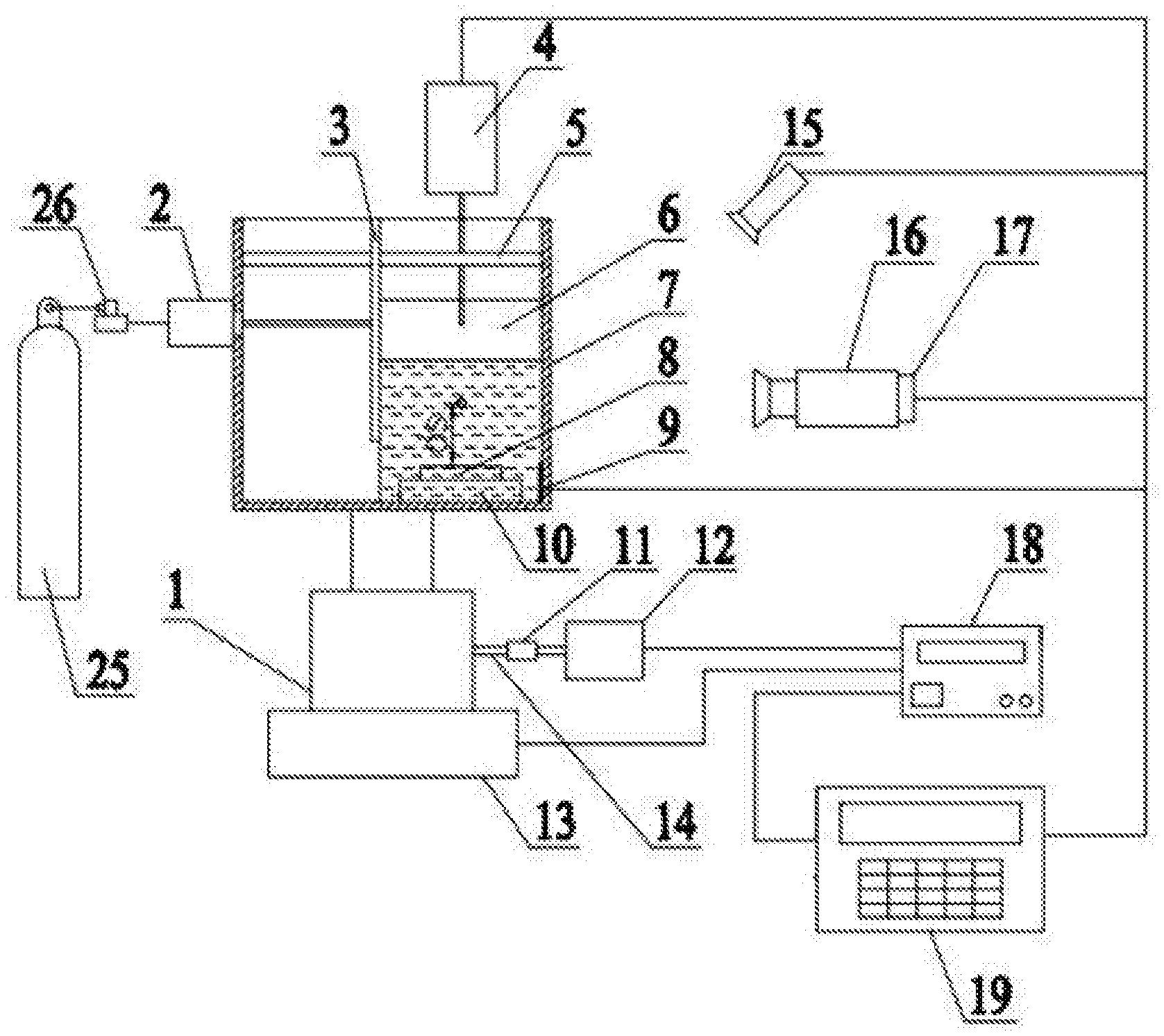
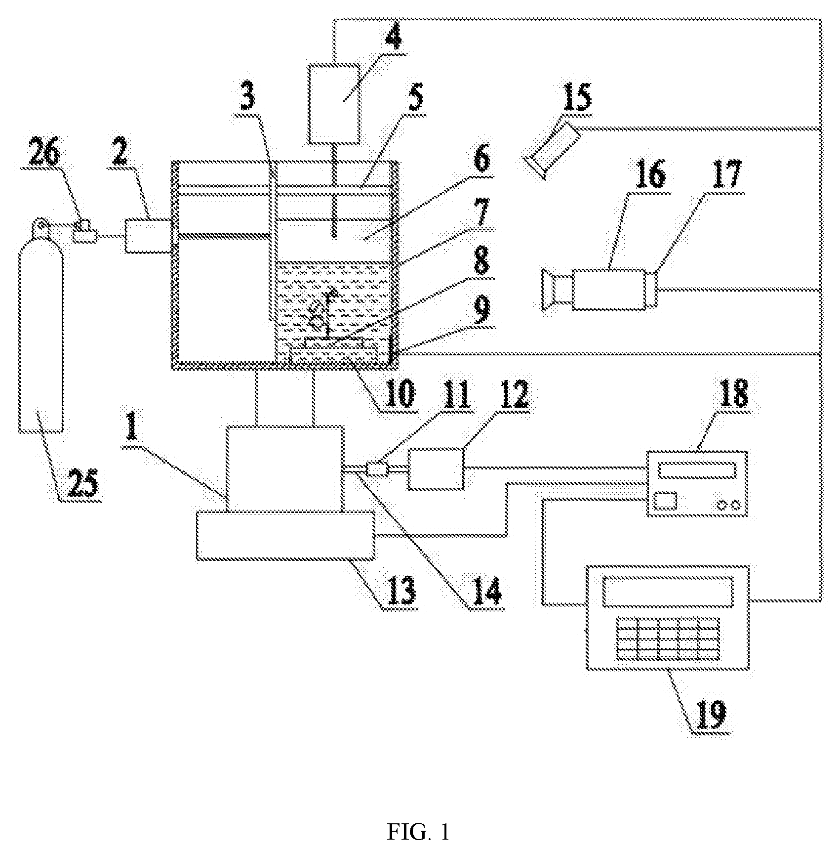
FIG. 1 is the main view of the apparatus.
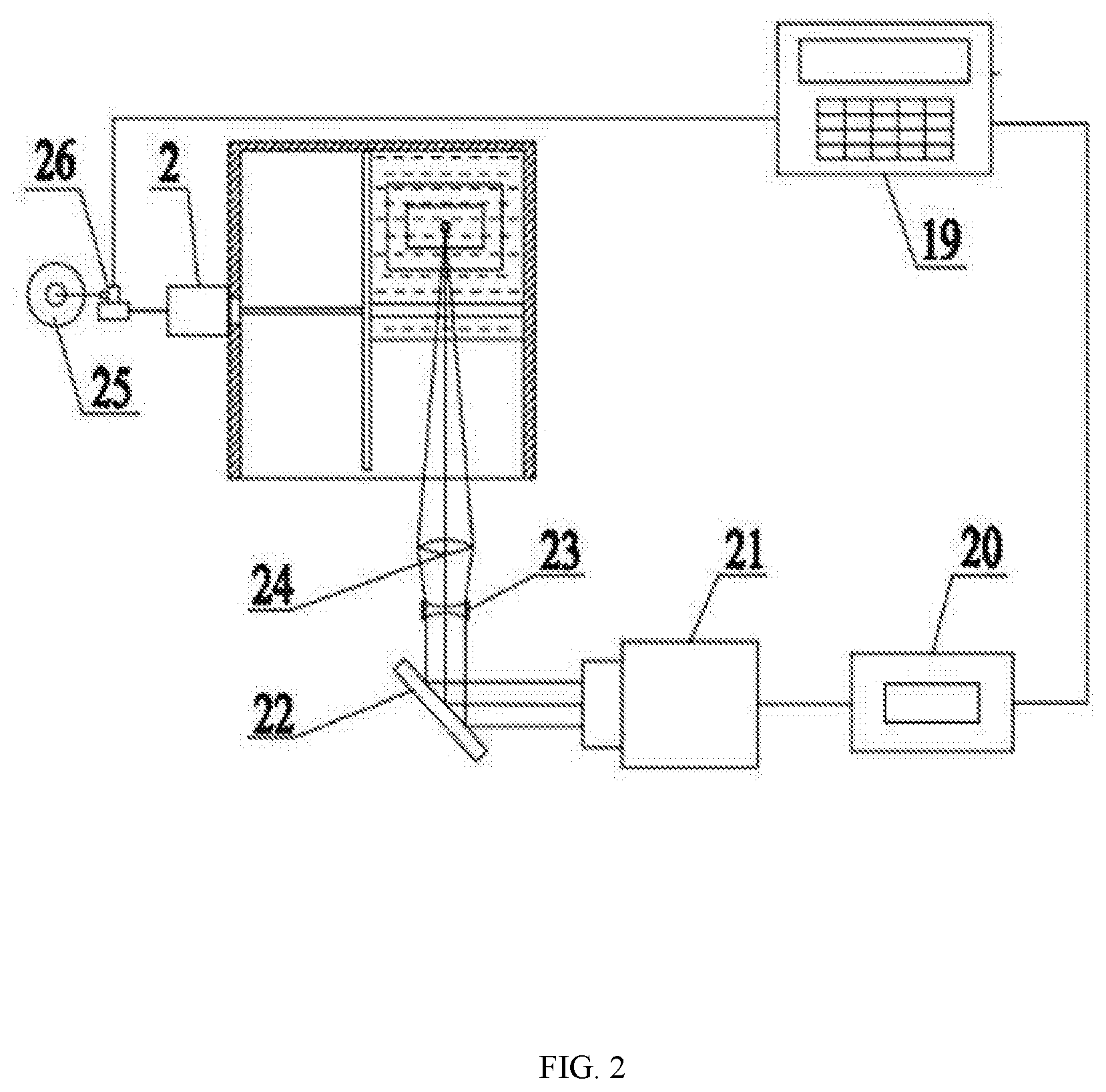
FIG. 2 is the top view of the apparatus.
In the drawings: (1) lifting platform, (2) cylinder, (3) movable plate, (4) hydrophone, (5) guide rod, (6) water tank, (7) fixing station, (8) target, (9) temperature sensor, (10) cushion block, (11) coupling, (12) servo motor, (13) two-axis platform, (14) shaft, (15) lighting flash, (16) high speed camera, (17) CCD, (18) CNC servo system, (19) computer, (20) laser controller, (21) YAG laser, (22) 45.degree. mirror, (23) beam expanding lens, (24) focusing lens, (25) nitrogen tank, (26) electromagnetic valve.
DETAILED DESCRIPTION OF THE EMBODIMENTS
As shown in FIGS. 1 and 2, the above apparatus includes laser cavitation device and fixing station (7). The laser cavitation device includes laser controller (20), YAG laser (21), 45.degree. mirror (22), beam expanding lens (23), focusing lens (24). The laser controller (20) controls YAG laser (21) to emit laser. The laser beam passes the 45.degree. mirror (22), beam expanding lens (23), focusing lens (24), and side wall of water tank (6) to focus in the water tank (6). The water tank (6) is on the fixing station (7) and a cushion block (10) is put in the water tank (6). A guide rod (5) is mounted on the upper end of the fixing station (7) and a movable plate (3) is mounted on the guide rod (5). The movable plate (3) is connected to the moving pair of guide rod (5) and the piston rod of the cylinder (2). The cylinder (2) is connected to nitrogen tank (25) though electromagnetic valve (26). There is a temperature sensor (9) on the side wall of water tank (6). The temperature sensor (9) is connected to computer (19). Above the water tank (6), there is a hydrophone (4) connected to computer (19), which is used for recording acoustic signal of cavitation. The imaging system includes flash light (15), high speed camera (16), and CCD (17). The flash light (15), high speed camera (16), and CCD (17) are all connected to computer (19) to record the pulsating and collapse of the cavitation bubbles. The fixing station (7) is on the lifting system. The lifting system includes lifting platform (1) and the fixing station (7) is on the lifting platform (1). The lifting platform is connected to CNC servo system (18) through shaft (14), coupling (11), and servo motor (12). The lifting system is on the two-axis platform (13). The laser beam emitted from laser cavitation device is focused in water tank (6) after passing through the side wall of it. The above device is connected to computer (19). The above lifting system and two-axis platform (13) are connected to computer (19) through CNC servo system (18).
During the operation, the target (8) and cushion block (10) are cleaned with ethanol or acetone and put into the right place of water tank (6). The water tank is put on the fixing station (7) and the purified water is filled into the water tank until the target (8) and cushion block (10) are submerged. The water temperature obtained from temperature sensor (9) during laser cavitation can be seen on computer screen in real time. Computer (19) is controlling the fixing system and lifting system. The YAG laser (21) emits laser after the laser parameters (laser energy, laser wavelength, beam spot size) are set on laser controller (20). The cavitation is generated after amplifying the laser energy. The experiment data are analyzed and the residual stress distribution is measured after cleaning the target (8) surface. Adjust the lifting system and change the water temperature to repeat the above operation until the optimal strengthening distance ds is obtained (ds is the distance between target (8) surface and laser focus point in the water tank (6)). Keep the ds unchanged and process the whole target (8) surface with control of two-axis platform (13) by computer (19). In order for further study of the laser cavitation process with optimal situation, the hydrophone and imaging system send signals to computer (19) so that the researchers can make observation and research to cavitation process in details.
It should be noticed that the above content is only illustrating the technical scheme rather than limit the scope of protection of the current invention. The simple modification or equivalent replacement of the technical scheme made by technicians in this field does not separate from the nature and extent of the technical scheme of this invention.
* * * * *
D00000
D00001
D00002
XML
uspto.report is an independent third-party trademark research tool that is not affiliated, endorsed, or sponsored by the United States Patent and Trademark Office (USPTO) or any other governmental organization. The information provided by uspto.report is based on publicly available data at the time of writing and is intended for informational purposes only.
While we strive to provide accurate and up-to-date information, we do not guarantee the accuracy, completeness, reliability, or suitability of the information displayed on this site. The use of this site is at your own risk. Any reliance you place on such information is therefore strictly at your own risk.
All official trademark data, including owner information, should be verified by visiting the official USPTO website at www.uspto.gov. This site is not intended to replace professional legal advice and should not be used as a substitute for consulting with a legal professional who is knowledgeable about trademark law.