Stationary exercise apparatus
Liao , et al. October 27, 2
U.S. patent number 10,814,160 [Application Number 16/104,944] was granted by the patent office on 2020-10-27 for stationary exercise apparatus. This patent grant is currently assigned to Johnson Health Tech. Co., Ltd.. The grantee listed for this patent is Joe Chen, Hung-Mao Liao. Invention is credited to Joe Chen, Hung-Mao Liao.


View All Diagrams
| United States Patent | 10,814,160 |
| Liao , et al. | October 27, 2020 |
Stationary exercise apparatus
Abstract
A stationary exercise apparatus includes a frame; two moving members respectively coupled to the frame, one end portion of each moving member located to define a swing axis; two swing members, one end portion of each swing member pivotally joined to the swing axis of the moving members; two supporting members respectively connected to the swing members, wherein one end portion of each supporting member is movably coupled to the frame, the other end portion of each supporting member is joined to the respective swing member so that one end portion of each supporting member moves along a reciprocating path; and two pedal sets respectively coupled to the supporting members, the pedal sets moving along a first path while the one end portions of the supporting members are reciprocating along the reciprocating path and the other end portions of the supporting members are rotating about a rotating axis.
| Inventors: | Liao; Hung-Mao (Taichung, TW), Chen; Joe (Taichung, TW) | ||||||||||
|---|---|---|---|---|---|---|---|---|---|---|---|
| Applicant: |
|
||||||||||
| Assignee: | Johnson Health Tech. Co., Ltd.
(Taichung, TW) |
||||||||||
| Family ID: | 1000005140060 | ||||||||||
| Appl. No.: | 16/104,944 | ||||||||||
| Filed: | August 19, 2018 |
Prior Publication Data
| Document Identifier | Publication Date | |
|---|---|---|
| US 20190038929 A1 | Feb 7, 2019 | |
Related U.S. Patent Documents
| Application Number | Filing Date | Patent Number | Issue Date | ||
|---|---|---|---|---|---|
| 15095901 | Apr 11, 2016 | 10369403 | |||
| 13782798 | May 17, 2016 | 9339684 | |||
| 13335437 | May 26, 2013 | 8403815 | |||
| 12773849 | Jan 10, 2012 | 8092349 | |||
| 11497783 | May 25, 2010 | 7722505 | |||
| 11434541 | Mar 23, 2010 | 7682290 | |||
Foreign Application Priority Data
| Nov 4, 2005 [CN] | 2005 1 0115518 | |||
| Jul 27, 2006 [CN] | 2006 1 0103811 | |||
| Current U.S. Class: | 1/1 |
| Current CPC Class: | A63B 24/00 (20130101); A63B 21/4034 (20151001); A63B 22/0015 (20130101); A63B 22/0056 (20130101); A63B 22/205 (20130101); A63B 21/225 (20130101); A63B 22/0023 (20130101); A63B 22/04 (20130101); A63B 22/001 (20130101); A63B 22/0664 (20130101); A63B 2022/0051 (20130101); A63B 2022/206 (20130101); A63B 2225/09 (20130101); A63B 2022/0676 (20130101); A63B 2022/067 (20130101) |
| Current International Class: | A63B 22/00 (20060101); A63B 24/00 (20060101); A63B 22/04 (20060101); A63B 21/00 (20060101); A63B 21/22 (20060101); A63B 22/20 (20060101); A63B 22/06 (20060101) |
References Cited [Referenced By]
U.S. Patent Documents
| 5383829 | January 1995 | Miller |
| 5540637 | July 1996 | Rodgers, Jr. |
| 5573480 | November 1996 | Rodgers, Jr. |
| 5685804 | November 1997 | Whan-Tong |
| 5788609 | August 1998 | Miller |
| 5813949 | September 1998 | Rodgers, Jr. |
| 5893820 | April 1999 | Maresh |
| 5910072 | June 1999 | Rawls |
| 5916065 | June 1999 | McBride |
| 5924962 | July 1999 | Rodgers, Jr. |
| 5938567 | August 1999 | Rodgers, Jr. |
| 6004244 | December 1999 | Simonson |
| 6126573 | October 2000 | Eschenbach |
| 6135926 | October 2000 | Lee |
| 6146313 | November 2000 | Whan-Tong |
| 6168552 | January 2001 | Eschenbach |
| 6422977 | July 2002 | Eschenbach |
| 6440042 | August 2002 | Eschenbach |
| 7169087 | January 2007 | Ercanbrack |
| 7278955 | October 2007 | Giannelli |
| 7316633 | January 2008 | Liao |
| 7347806 | March 2008 | Nakano |
| 7682290 | March 2010 | Liao |
| 7691034 | April 2010 | May |
| 7722505 | May 2010 | Liao |
| 7731634 | June 2010 | Stewart |
| 7736278 | June 2010 | Lull |
| 7766797 | August 2010 | Dalebout |
| 7785235 | August 2010 | Lull |
| 8092349 | January 2012 | Liao |
| 8403815 | March 2013 | Liao |
| 9339684 | May 2016 | Liao |
| 10369403 | August 2019 | Liao |
| 2003/0083177 | May 2003 | Tung |
| 2004/0209741 | October 2004 | Kuo |
| 2005/0202939 | September 2005 | Lull |
| 2006/0003868 | January 2006 | Lull |
| 2006/0189445 | August 2006 | Stewart |
Parent Case Text
CROSS-REFERENCE TO RELATED APPLICATION
This application is a Continuation-in-part of U.S. patent application Ser. No. 15/095,901, filed on Apr. 11, 2016, which is a continuation of U.S. patent application Ser. No. 13/782,798, filed on Mar. 1, 2013, now U.S. Pat. No. 9,339,684, which is a continuation of U.S. patent application Ser. No. 13/335,437, filed on Dec. 22, 2011, now U.S. Pat. No. 8,403,815, which is a continuation of U.S. patent application Ser. No. 12/773,849, filed on May 5, 2010, now U.S. Pat. No. 8,092,349, which is a continuation of U.S. patent application Ser. No. 11/497,783, filed on Aug. 2, 2006, now U.S. Pat. No. 7,722,505, which claims the benefit of Chinese patent application no.: 200610103811.X, filed on Jul. 27, 2006, and is a continuation-in-part of U.S. patent application Ser. No. 11/434,541, filed on May 15, 2006, which issued as U.S. Pat. No. 7,682,290 on Mar. 23, 2010, which claims the benefit of Chinese patent application no.: 200510115518.0, filed Nov. 4, 2005, each of which is incorporated by reference in their entireties.
Claims
What is claimed is:
1. A stationary exercise apparatus, comprising: a frame; two moving members, each moving member having a first end portion and a second end portion, the first end portions of the two moving members respectively pivotally coupled to the frame to move the second end portions of the two moving members forward and backward; two swing members, each swing member having an upper portion and a lower portion, the upper portions of the two swing members respectively pivotally coupled to the second end portions of the moving members about a swing axis; two supporting members, each supporting member having a first end portion and a second end portion, the first end portions of the two supporting members respectively coupled to the frame to rotate about a rotating axis, the second end portions of the two supporting members respectively coupled to the swing members; and two pedals respectively coupled to the lower portions of the two swing members, the pedals moving along a reciprocating path while the first end portions of the two supporting members are rotating about the rotating axis; wherein, the swing axis is movable forward or backward when the second end portions of the two moving members is adjusted forward or backward, and the reciprocating path of the two pedals is changed at the same time.
2. The stationary exercise apparatus of claim 1, wherein the reciprocating path is an arc path.
3. The stationary exercise apparatus of claim 1, wherein the reciprocating path having a front end and a rear end, and the swing axis is positioned higher than the front end of the reciprocating path.
4. The stationary exercise apparatus of claim 1, wherein the orientations of the pedals are respectively adjustable relative to the corresponding supporting members.
5. A stationary exercise apparatus, comprising: a frame having a front; two supporting members, each supporting member having a first end portion and a second end portion, the first end portions of the supporting members respectively coupled to the frame to rotate along a first path about a first axis; two swing members, each swing member having an upper portion and a lower portion, the swing members respectively connected to the second end portions of the supporting members; two pedals respectively coupled to the lower portions of the two swing members, the pedals moving along a second path while the first end portions of the supporting members are rotating about the first axis; and two moving members respectively coupled to the frame and being movable relative to the frame, the Upper portions of the swing members respectively pivotally joined to the moving members about a swing axis such that the upper portions of the swing members and the swing axis are adjustable relative to the frame; wherein at least one geometry parameter of the second path could be varied while the swing axis is being adjusted relative to the frame.
6. The stationary exercise apparatus of claim 5, wherein the second path is an arc path.
7. The stationary exercise apparatus of claim 5, wherein the second path is a reciprocating path.
8. The stationay exercise apparatus of claim 7, wherein the reciprocating path has a front end and a rear end, and wherein the rear end of the reciprocating path is positioned farther from the front of the frame than the swing axis.
9. The stationary exercise apparatus of claim 7, wherein the reciprocating path has a front end and a rear end, and the swing axis is positioned higher than the front end of the reciprocating path.
10. The stationary exercise apparatus of claim 5, wherein the geometry parameter is an incline level of the second path and the incline level of the second path could be increased while the swing axis is being adjusted rearward relative to the front of the frame.
11. The stationary exercise apparatus of claim 5, wherein orientations of the pedals are respectively adjustable relative to the corresponding swing members.
12. The stationary exercise apparatus of claim 5, wherein the pedals move toward opposite directions relative to a balance position.
Description
BACKGROUND
1. Field of the Invention
This present disclosure relates to a stationary exercise apparatus, and more particularly to a leg exercise apparatus.
2. Description of Related Art
Stationary exercise apparatus have been popular for several decades. Early exercise apparatus typically had a single mode of operation, and exercise intensity was varied by increasing apparatus speed. More recently, enhancing exercise intensity in some apparatus has been made by adjusting the moving path of user's feet, such as by adjusting the incline or stride length of user's foot path.
U.S. Pat. No. 5,685,804 discloses two mechanisms for adjusting the incline of a stationary exercise apparatus, one of them having a linear track which can be adjusted and the other having a length adjusting swing arm. The swing arm lower end can be moved upwardly for a high incline foot path. U.S. Pat. No. 6,168,552 also discloses a stationary exercise apparatus having a linear track for changing the incline of the stationary exercise apparatus. U.S. Pat. No. 6,440,042 discloses a stationary exercise apparatus having a curved track for adjusting the incline of the stationary exercise apparatus.
Nonetheless, there is still a need for an exercise apparatus that can increase varieties of exercise and enhance exercise intensity of a user.
SUMMARY
A stationary exercise apparatus includes a frame; two moving members respectively coupled to the frame, one end portions of the moving members located to define a swing axis; two swing members, one end portions of the swing members respectively pivotally joined to the swing axis of the moving members; two supporting members respectively connected to the swing members, wherein one end portions of the supporting members are movably coupled to the frame, the other end portions of the supporting members are respectively joined to the swing members so that one end portions of the supporting members moving along a reciprocating path; and two pedal sets respectively coupled to the supporting members, the pedal sets moving along a first path while the one end portions of the supporting members are reciprocating along the reciprocating path and the other end portions of the supporting members are rotating about a rotating axis.
BRIEF DESCRIPTION OF THE DRAWINGS
FIG. 1 is a perspective view of a stationary exercise apparatus according to an embodiment of the present disclosure;
FIG. 2 is a side view of the stationary exercise apparatus of FIG. 1 in a rotating position of a low incline condition;
FIG. 3 is a top view of the stationary exercise apparatus of FIG. 1;
FIG. 4 is a back view of the stationary exercise apparatus of FIG. 1;
FIG. 5 is a side view of the stationary exercise apparatus of FIG. 1 in another rotating position of the low incline condition;
FIG. 6 is a side view of the stationary exercise apparatus of FIG. 1 in a rotating position of a high incline condition;
FIG. 7 is a side view of the stationary exercise apparatus of FIG. 1 in another rotating position of the high incline condition demonstrating better gluteus exercise of a user;
FIG. 8 are toe and heel path profiles of the stationary exercise apparatus of FIG. 1 in a relatively low incline condition;
FIG. 9 are toe and heel path profiles of the stationary exercise apparatus of FIG. 1 in a relatively high incline condition;
FIG. 10 is a perspective view of a stationary exercise apparatus according to another embodiment of the present disclosure;
FIG. 11 is a side view of the stationary exercise apparatus of FIG. 10;
FIG. 12 is a top view of the stationary exercise apparatus of FIG. 10;
FIG. 13 is a back view of the stationary exercise apparatus of FIG. 10;
FIG. 14 is a perspective view of a third embodiment of a stationary exercise device in accordance with the present disclosure;
FIG. 15 is a side view of the stationary exercise apparatus of FIG. 14;
FIG. 16 is a top view of the stationary exercise apparatus of FIG. 14;
FIG. 17 is a left side perspective view of a fourth embodiment of a stationary exercise device in accordance with the present disclosure;
FIG. 18 is a right side perspective view of the stationary exercise apparatus of FIG. 17;
FIG. 19 is a left side view of the stationary exercise apparatus of FIG. 17 in a relatively low incline condition;
FIG. 20 is a left side view of the stationary exercise apparatus of FIG. 17 in a relatively high incline condition;
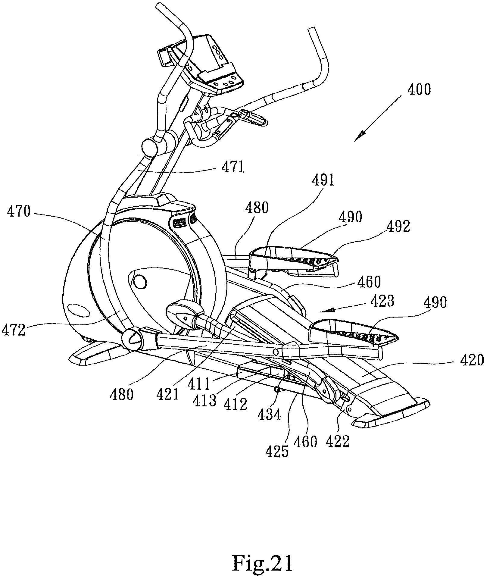
FIG. 21 is a left side perspective view of the stationary exercise apparatus of FIG. 17 in a relatively high incline condition;
FIG. 22 is a left side view of the guide assembly of the stationary exercise apparatus of FIG. 17 in a relatively low incline condition;
FIG. 23 is a left side view of the guide assembly of the stationary exercise apparatus of FIG. 17 in a relatively high incline condition;
FIG. 24 is a left side view of an alternative embodiment of the guide assembly of the stationary exercise apparatus of FIG. 17 in a relatively high incline condition;
FIG. 25 shows toe and heel path profiles of the stationary exercise apparatus of FIG. 17 in a relatively low incline condition;
FIG. 26 shows toe and heel path profiles of the stationary exercise apparatus of FIG. 17 in a relatively high incline condition;
FIG. 27 is a perspective view of a stationary exercise apparatus according to a fifth embodiment of the present disclosure;
FIG. 28 is a side view of the stationary exercise apparatus of FIG. 27
FIGS. 29.about.31 are perspective side views of a stationary exercise apparatus according to a sixth embodiment of the present disclosure with the swing axis in a first position, in a second position, and in a third position;
FIGS. 32.about.34 are path information and geometry parameters of the stationary exercise apparatus of FIGS. 29.about.31 in a first position, in a second position, and in a third position;
FIGS. 35.about.37 are perspective side views of a stationary exercise apparatus according to a seventh embodiment of the present disclosure with the swing axis in a first position, in a second position, and in a third position.
DETAIL DESCRIPTION
Referring now specifically to the figures, in which identical or similar parts are designated by the same reference numerals throughout, a detailed description of the present disclosure is given. It should be understood that the following detailed description relates to the best presently known embodiment of the disclosure. However, the present disclosure can assume numerous other embodiments, as will become apparent to those skilled in the art, without departing from the appended claims.
Now referring to FIG. 1, a stationary exercise apparatus 100 is illustrated therein. The stationary exercise apparatus 100 has a frame 110 generally comprising a base 111, a front portion 112, a rear portion 108, and side portions 113. The base 111 is substantially a horizontal frame adapted to stably rest on a ground, floor or other similar supporting surface. The front portion 112 is fixed on the base 111, and preferably includes a post 114 and a standard 115. The side portions 113 are respectively mounted on the left and right sides of the base portion 111. A fixed handle assembly 180 and a console 190' are mounted on or near the upper end of the standard 115. Left and right cranks 132 (FIG. 2) are each pivoted to one portion of the frame 110 defining a first axis 134 and in the illustrated embodiment, the first axis 134 is at or near the front portion of the frame 110. The left and right cranks 132 could be replaced by a pair of disks, flywheels, or other device rotating about the first axis 134. The left and right cranks 132 and the first axis 134 can also be replaced by a pair of closed tracks circulating about a virtual axis, as opposed to an axis defined by a wheel axle. The frame 110 may further comprise a pulley 131 and a resistance member 133 which is controlled by using the console 190' to vary operating resistance for a user.
Now referring to FIGS. 1 and 2, the frame 110 further comprises a moving assembly 141 mounted on the side portions 113 respectively. In a preferred embodiment of the present disclosure as shown in FIG. 1, the moving assembly 141 has first and second moving members 142, in a generally upright position, and a lateral link 143 (FIG. 4) connecting the first and second moving members 142 to one another. The first and second moving members 142 are joined to the side portions 113 via a second axis 144 so that the upper end portions of the first and second moving members 142 can be adjusted by pivoting the first and second moving members 142 about the second axis 144. There is an optional adjusting assembly 145 mounted between the moving assembly 141 and the frame 110 for adjusting the moving assembly 141 about the second axis 144. The preferred embodiment of the adjusting assembly 145 generally includes a motor 146, a screw rod 147, and a screw tube 148. The motor 146 has one end connected to the base portion 111 and the other end connected to one end of the screw rod 147. The other end of the screw rod 147 is connected to one end of the screw tube 148. The other end of the screw tube 148 is connected to the moving assembly 141 so that the effective length of the screw rod 147 and the screw tube 148 combination is adjustable to move the lower end of the first and second moving members 142 fore and aft. As the lower ends move, the upper ends of the first and second moving members 142 are pivoted in the opposite direction about the second axis 144. The upper end portions of the first and second moving members 142 are adjustable anywhere between a first position as shown in FIG. 2 and a second position as shown in FIG. 6. Although described and illustrated as a screw adjusting mechanism, the adjusting assembly 145 could be any manual or automatic mechanical, electromechanical, hydraulic, or pneumatic device and be within the scope of the invention. The adjusting assembly 145 is illustrated as being mounted on the right side of the exercise device 100, but both moving members 142 are adjusted because the lateral link 143 (FIG. 4) transfers the force to the left side moving member 143.
Referring to FIGS. 2 and 4, the stationary exercise apparatus 100 comprises first and second swing members 149a/149b, each of the swing members 149a/149b having an upper portion 150 and a lower portion 151. The upper portions 150 of the first and second swing members 149a/149b can be coupled to the frame 110 via a swing axis 159 for swinging motion relative to the frame 110. In the embodiment of the present disclosure, the upper portions 150 of the first and second swing members 149a/149b are respectively pivoted to the first and second moving members 142 via the swing axis 159 so that the swing axis 159 can be adjusted forward or backward anywhere between the first position shown in FIG. 2 and the second position shown in FIG. 6. Different positions of the swing axis 159 cause different exercise intensity of the stationary exercise apparatus 100.
Now referring to FIGS. 2, 4 and 5, the stationary exercise apparatus 100 comprises first and second supporting members 120a/120b, each of the first and second supporting members 120a/120b having a first end portion 153 and a second end portion 154. The first end portions 153 of the first and second supporting members 120a/120b are respectively coupled to the frame 110 to rotate about the first axis 134. In the embodiment of the present disclosure, the first end portions 153 of the first and second supporting members 120a/120b are respectively pivoted to the left and right cranks 132 to rotate about the first axis 134. As mentioned previously, the left and right cranks 132 may be replaced by flywheels or disks and the like. The second end portions 154 of the first and second supporting members 120a/120b are respectively pivoted to the lower portions of the first and second swing members 149a/149b so that the second end portions 154 of the first and second supporting members 120a/120b may be moved along a reciprocating path 190 (as shown in FIGS. 2 and 5) while the first end portions 153 of the first and second supporting members 120a/120b are being rotated about the first axis 134.
Referring to FIGS. 1 through 6, the stationary exercise apparatus 100 further comprises first and second control links 160a/160b respectively pivotally connected to the first and second supporting members 120a/120b. Each of the first and second control links 160a/160b has a first end portion 155 and a second end portion 156. The first end portions 155 of the first and second control links 160a/160b are movably coupled to the frame 110. In the embodiment of the present disclosure, the first end portions 155 of the first and second control links 160a/160b are respectively connected to first and second handle links 171a/171b. More specifically, each of the first and second handle links 171a/171b has lower and upper end portions. The lower end portions 157 of the first and second handle links 171a/171b are respectively pivoted to the first end portions 155 of the first and second control links 160a/160b and the upper end portions 158 of the first and second handle links 171a/171b are pivoted to the frame 110 so that, the first and second handle links 171a/171b can guide the first end portions 155 of the first and second control links 160a/160b in a reciprocating path. There are several alternatives of performing the same function of the first and second handle links 171a/171b. For example, the frame 110 can include a pair of tracks allowing the first end portions 155 of the first and second control links 160a/160b movably coupled to the tracks via rollers or sliders. For simplicity, all such alternatives are referred to herein as "handle links" even when they do not serve as handles for the user.
Still referring to FIGS. 1 through 6, the stationary exercise apparatus 100 includes first and second pedals 150a/150b respectively coupled to the first and second supporting members 120a/120b. In the embodiment of the present disclosure, the first and second pedals 150a/150b are indirectly connected to the first and second supporting members 120a/120b. More specifically, the first and second pedals 150a/150b are respectively attached to the second end portions 156 of the first and second control links 160a/160b which are pivotally connected to the first and second supporting members 120a/120b. Therefore, rear end portions 158 of the first and second pedals 150a/150b are directed by the first and second supporting members 120a/120b to move along a second closed path 198 (FIGS. 2, 5, and 6) while the first end portions 153 of the first and second supporting members 120a/120b rotating about the first axis 134. The first and second pedals 150a/150b can also be directly attached to the first and second supporting members 120a/120b, similar to the teaching of U.S. Pat. No. 5,685,804. It should be noticed that both indirect and direct connections between the first and second pedals 150a/150b and the first and second supporting members 120a/120b can cause the rear end portions of the first and second pedals 150a/150b to move along similar closed paths, and are within the scope of the present invention.
Now referring to FIGS. 2 and 5, the reciprocating path 190 of the first and second swing members 149a/149b has a rear end 192, a front end 194, and a middle point 196. The middle point 196 is substantially the middle point between the rear end 192 and the front end 194. As shown in FIG. 2, the second end portion 154 of the second support member 120b is being at the rear end 192 of the reciprocating path 190 while the first end portion 153 of the second supporting member 120b is being approximately at the rearmost position during rotating about the first axis 134. As also shown in FIG. 5, the second end portion 154 of the second support member 120b is being at the front end 194 of the reciprocating path 190 while the first end portion 153 of the second supporting member 120b is being approximately at the foremost position during rotating about the rotating axis 134. In the embodiment of the present disclosure, the reciprocating path 190 is substantially arcuate because of the swing motion of the first and second swing members 149a/149b, but the present disclosure is not limited to an arcuate reciprocating path. It should be noticed that relative positions between the swing axis 159 and the reciprocating path 190 can cause different exercise intensity of the stationary exercise apparatus 100. As illustrated in FIG. 2, the swing axis 159 is positioned higher than the front end 194.
More specifically, the positions of the swing axis 159 can determine incline levels of both the reciprocating path 190 and the second closed path 198. If the swing axis 159 is substantially vertically above the middle point 196 of the reciprocating path 190, the incline level of both the reciprocating path 190 and the second closed path 198 are substantially horizontal. If the swing axis 159 is positioned rearward in view of an orientation of an operating user, the incline levels of both the reciprocating path 190 and the second closed path 198 are increased. A higher incline level of the second closed path 198 creates higher exercise intensity of a user. As shown in FIG. 2, the swing axis 159 is positioned slightly in back of the middle point 196 of the reciprocating path 190 so that the second closed path 198 is slightly inclined and the exercise intensity is enhanced. In order to obtain higher exercise intensity, the swing axis 159 can be re-positioned farther toward the rear. As shown in FIG. 6, the swing axis 159 is in back of the rear end 192 of the reciprocating path 190 and both the reciprocating path 190 and the second closed path 198 are in a relatively high incline level so that the exercise intensity of the stationary exercise apparatus 100 is further increased.
In an embodiment of the present disclosure, the adjusting assembly 145 can be controlled via the console 190' to vary the incline level of the second closed path 198 and to adjust the exercise intensity of the stationary exercise apparatus 100. As mentioned previously, the upper portions 150 of the first and second swing members 149a/149b are coupled to the moving assembly 141 of the frame 110. The adjusting assembly 145 is connected between the lateral link 143 (FIG. 5) of the moving assembly 141 and the frame 110. Therefore, a user can electronically actuate the adjusting assembly 145 to vary the position of the swing axis 159 and adjust the incline level of the second closed path 198. It should be noted that the (lateral) link 143 could be omitted in some embodiments, not shown in the figures. For example, two adjusting assemblies 145 are directly connected to the first and second moving members 142 respectively. The benefit of omitting the (lateral) link 143 is that the height of the first and second pedal 150a/150b could be lower because of less interference between the (lateral) link 143 and the second end portions of the first and second supporting members 120a/120b. A user may feel more comfortable in a lower operating position. It should also be noticed that the incline level of the stationary exercise apparatus 100 is not limited to an electronically adjustment. Some manual adjustments, such as pin and holes combinations, levers, cranks and the like are also within the scope of the present invention.
FIG. 5 shows the swing axis 159 is positioned to the rear of the middle point 196 of the reciprocating path 190 and the second closed path 198 is in a low incline level. FIG. 6 shows the swing axis 159 is positioned to the rear of the rear end 192 of the reciprocating path 190 and the second closed path 198 is in a higher incline level. In other embodiments of the present disclosure, the incline level of the second closed path 198 could also be non-adjustable. For example, the side portions 113 of the frame 110 extend upwardly and the first and second swing members 149a/149b are directly pivoted to the side portions 113 of the frame 110. In the non-adjustable embodiments, when the swing axis 159 is positioned slightly in back of the middle point 196, the second closed path 198 is in the low incline level, not flat, such as shown in FIG. 5. When the swing axis 159 is positioned in back of the rear end 192 of the reciprocating path 190, the second closed path 198 would be in the high incline level as shown in FIG. 6. Both the low and high incline level of the stationary exercise apparatus 100 can enhance exercise intensity of a user, comparing to a more horizontal incline level.
To operate the stationary exercise apparatus 100, a user respectively steps on the first and second pedals 150a/150b and grabs on the fixed handle assembly 180 or a pair of moving handles 172a/172b. The first end portions 153 of the first and second supporting members 120a/120b rotate along a substantially arcuate path about the first axis 134 and the second ends of the first and second supporting members 120a/120b move along the reciprocating path 190. Therefore, rear end portions of the first and second pedals 150a/150b move along the second closed path 198. As mentioned previously, the positions of the swing axis 159 are relative to some geometry parameters of the second closed path 198 and have great effects on the exercise intensity of a user of the stationary exercise apparatus 100.
To better present the relationship between the swing axis 159 and the second closed path 198, separated path information is illustrated in FIGS. 8 and 9. FIG. 8 shows the path information and geometry parameters while the swing axis 159 is slightly in back of the middle point 196 as shown in FIG. 5. FIG. 9 shows the path information and geometry parameters while the swing axis 159 is to the rear of the rear end 192.
Now referring to FIG. 8 in more detail, the second closed path 198 is represented by eight correspondent points, a.about.h. The correspondent points a and e are the foremost and rearmost positions of the first ends of the first and second supporting members 120a/120b during rotating about the first axis 134. Each point is separated in an equal angle of forty-five degrees relative to the angle of rotation about the first axis 134. A stride length SL2 constituted by the correspondent points a and e is also one of the geometry parameters of the second closed path 198, in addition to the incline level. The stride length SL2 is substantially the stride length of the heel portion of a user because the second closed path 198 is the moving path of the rear ends of the pedals 150a/150b and the heel portion of a user is approximate to the rear ends of the pedals 150a/150b. Stride length is also relative to exercise intensity. A longer stride length generally results in higher exercise intensity. A third closed path 197 is the moving path of the front ends of the pedals 150a/150b. A stride length SL3 may also substantially represent the stride length of the toe portion of a user. Because the closed paths 198 and 197 are moving paths of the rear and front ends of the pedals 150a/150b, the orientation of the pedals 150a/150b can be illustrated by a pedal orientation 151' as shown in FIG. 8. One important character of the pedal orientation 151' is that the steepness of the pedal orientation 151' is increased when the swing axis 159 is adjusted backwardly.
Now referring to FIGS. 7 and 9 show the stride length SL2, stride length SL3, pedal orientation 151', second closed path 198, and third closed path 197 while the swing axis 159 is in back of the rear end 192 of the reciprocating path 190. As shown in FIG. 7, the first and second control links 160a/160b are respectively pivoted to the first and second supporting members 120a/120b via pivot axes 161. The incline level of the second closed path 198 of FIG. 9 is increased by 17 degrees compared to the incline level of FIG. 8, but the incline level of the third closed path 197 of FIG. 9 is only increased by 11 degrees. That is, the incline level of the second closed path 198 is increased more than the incline level of the third closed path 197 while the swing axis 159 is being adjusted backwardly. The stride length SL2 of FIG. 9 is increased by about 15 percent compared to the stride length SL2 as shown in FIG. 8, but the stride length SL3 of FIG. 9 is only increased by about 6 percent. That is, the stride length SL2 is increased more than the stride length SL3 while the swing axis 159 is being adjusted backwardly. Because both path inclination and stride length of the heel portion of a user are increased more than the toe portion, the exercise intensity of the heel portion is higher than the exercise intensity of the toe portion of a user which may also imply a higher exercise intensity of the gluteus of a user. Because the heel portion of the user is obviously elevated as shown in FIG. 7, the thigh of the user is elevated to a substantially horizontal orientation relative to the ground surface so that the gluteus of the user is fully exercised.
Now referring to FIGS. 10 through 13, a second embodiment of the present disclosure is shown. A stationary exercise apparatus 200 comprises a frame 210 having a base portion 211 adapted to rest on a surface. The frame 210 further comprises a front portion 212 extending upwardly from the base portion 211, a side portion 214 extending longitudinally rearward from the front portion 212, and a rear portion 213 connecting the side portion 214 and the base portion 211.
The stationary exercise apparatus 200 further has first and second supporting members 220, each of the supporting members 220 having a first end portion and a second end portion. The first end portions of the first and second supporting members 220 are respectively pivoted to a pair of rotating members (not shown) in order to rotate about a first axis 234. The second end portions of the first and second supporting members 220 are respectively connected to the lower portions of first and second swing members 249. The upper portions of the first and second swing members 249 are coupled to the side portion 214 of the frame 210 via a swing axis 259. More specifically, the upper portions of the first and second swing members 249 are pivotally connected to left and right moving assemblies 241.
Each of the left and right moving assemblies 241 respectively comprises third and fourth moving members 242. Each of the third and fourth moving members 242 is connected to left and right adjusting assemblies 245 (FIG. 11) so that the moving assemblies 241 could be driven by the adjusting assemblies 245. Each of the left and right moving assemblies 241 further includes an optional roller 243. The rollers 243 are respectively engaged on the side portion 214 for increasing stability and smoothness of movement of the moving assemblies 241 along the side portion 214.
As illustrated in FIG. 13, each of the adjusting assemblies 245 includes a motor 246 mounted on one portion of the frame 210, a screw rod 247, and a screw member 248. The screw rod 247 has one end connected to the motor 246 and a portion adapted for movement of the screw member 248. Although described and illustrated as a screw adjusting mechanism, the adjusting assembly 245 could be any manual or automatic mechanical, electromechanical, hydraulic, or pneumatic device and be within the scope of the invention.
In the second embodiment of the present disclosure, the upper portions of the first and second swing members 249 are respectively pivoted to the third and fourth moving members 242. But, the upper portions of the first and second swing members 249 can also be directly pivoted to the screw members 248 of the adjusting assemblies 245. Therefore, actuating of the motor 246 can cause rotation of the screw rod 247 to change the positions of both the third and fourth moving member 242 and the swing axis 259.
Similar to the previous preferred embodiment of the stationary exercise apparatus 100, the stationary exercise apparatus 200 also comprises a pair of pedals 250 respectively coupled to the supporting members 220. Optionally, the stationary exercise apparatus 200 also has a pair of control links 260 respectively pivoted to the supporting members 220 and a pair of handle links 271 coupled to the frame 210 for guiding the control links 260.
FIGS. 14 through 16 illustrate an embodiment similar to the embodiment illustrated in FIGS. 1 through 9. This third embodiment of a stationary exercise apparatus 300 includes a frame 310 having a base 311, a front portion 312, a rear portion 308, and side portions 313. The frame 310 may also include a post 314 and a standard 315. A handle assembly 380 and a console 390 are also provided as described above in relation to the first and second embodiments.
The third embodiment of the exercise apparatus 300 includes rotating members 333 that rotate about a first axis 334, similar to those described and illustrated in relation to the second embodiment 200 (FIGS. 10 through 13). An optional resistance member is also provided.
Similar to the embodiment illustrated in FIGS. 1 to 9, the third embodiment of the exercise apparatus 300 also includes first and second supporting members 320a/320b, each having a first end portion 353 rotatably joined to the rotating members 333 and a second end portion 354. The second end portions 354 are respectively joined to swing members 349a/349b. The swing members 349a/349b are joined to the frame side portions 313 in a manner substantially similar to that described above in relation to the first embodiment 100.
There is also provided a moving assembly 341 including first and second moving member 342 that are defined by an upper portion 343 and a lower portion 355 joined at an elbow 356, so that the upper portion 343 and the lower portion 355 are at an angle to one another as illustrated. The first and second moving members 342 are joined to the side portions 313 via a second axis 344 to pivot as described above.
An optional adjusting assembly 345 is provided on each side of this embodiment. The adjusting assembly 345 activates the moving assembly 341 about the second axis 344. The adjusting assembly includes a motor 346, a screw rod 347, and a threaded nut, sleeve, or tube 348. The motor 346 is connected to the base 311 and to the screw rod 347. In this embodiment, the screw rod 347 is generally upright and angled slightly forward. The screw rod 347 is threaded through the tube 348, which is pivotally mounted on the lower portion 355 of the moving members 342. In this manner, the motor 346 can be activated automatically or manually from the console 390 to rotate the screw rod 347, which in turn raises or lowers the tube 348 along the screw rod 347. As the tube 348 is raised or lowered, the moving member 342 pivots about the second axis 344. A manually operated adjusting assembly could also be used, as described above.
In this embodiment of the exercise apparatus 300, the swing members 349a/349b are illustrated as arcuate in shape so that the support members 320a/320b need not extend rearward as far as those illustrated in previous embodiments. Otherwise, the operation of the swing member 349a/349b and the support members 320a/320b are essentially as described above.
First and second pedals 350a/350b are respectfully coupled to the first and second supporting members 320a/320b, either directly or indirectly. To couple the pedals 350a/350b indirectly to the support members 320a/320b, there are provided first and second control links 360a/360b which are pivotally connected to the support members 320a/320b. The pedals 350a/350b are joined to the control links 360a/360b and move in a second closed path when the support members 320a/320b move as described above.
Handle links 371a/371b are illustrated for this embodiment, and as with the above embodiments, may be substituted by tracks, rollers, sliders, and the like to provide support for the moving first end portions of the control links 360a/360b. Any such device is referred to herein as a "handle link" regardless of whether it actually serves as a handle for a user.
FIGS. 17 through 21 illustrate an embodiment having substantial portion similar to the embodiments illustrated in FIGS. 1 through 16. This fourth embodiment of a stationary exercise apparatus 400 includes a frame 410 having a base and a rear portion 425 (FIG. 20). The frame 410 may also include a front portion having a post 412 and a standard 413. A fixed handle assembly 415 and a console 414 are also provided as described above in relation to the previous embodiments.
The fourth embodiment of the exercise apparatus 400 includes rotating members 418 that rotate about a first axis 441, similar to those described and illustrated in relation to the second embodiment 200 (FIGS. 10 through 13). An optional resistance assembly 450 is also provided.
Similar to the embodiment illustrated in FIGS. 1 to 9, the fourth embodiment of the exercise apparatus 400 also includes first and second supporting members 460, each having a first end portion 461 rotatably joined to the rotating members 418 and a second end portion 463. Preferably, the second end portion is coupled with some rollers or sliders for reciprocating movement on a surface such as a track surface. The second end portions 463 of the first and second supporting members 460 are respectively reciprocated on a guider assembly 423 which is coupled to the rear portion 425 of the base 411. There is more detail description of the guider assembly 423 hereinafter.
Now referring to FIGS. 22 and 23, the guider assembly 423 comprises a guider 420 coupled to the rear portion 425 of the base 411 and a moving member 434 movably coupled between the guider 420 and the base 411. The guider 420 has a first end portion 421, and a second end portion 422 pivotally connected to the base 411. A reciprocating path 426 is defined between the first and second end portions 421/422 of the guider 420. In the embodiment illustrated in FIGS. 17 through 21, the guider 420 is a linear track to define the reciprocating path 426 substantially parallel to the surface of the guider 420. In other embodiments, the guider 420 could be a curved track (not shown), the reciprocating path 426 is a virtual linear line connecting first and second ends of the curved track. An incline angle 428 is defined by the reciprocating path 426 and the base 411 in both linear and curved track embodiments. More specifically, the incline angle 428 is defined by the reciprocating path 426 and the top horizontal surface of the base 411, or a ground surface on which the base 411 rests.
FIGS. 22 through 24 illustrate detailed views of the guider assembly 423 and an alternative embodiment of the guider assembly 423. In FIG. 22, the guider 420 is in a relatively low incline condition and the incline angle 428 defined by the guider 420 and the base 411 is about 5 degrees. The moving member 434 has a first end portion 436 pivotally connected to the base 411, and a second end portion 437 movably coupled to the guider 420. In FIG. 23, the second end portion 437 of the moving member 434 is selectively coupled to the guider 420 close to a middle position between the first and second end portions 421/422 of the guider 420. In the arrangement of FIG. 23, the moving member 434 is inclined further upwardly, and the incline angle 428 is increased to about 22 degrees. The exercise apparatus 400 is in a relatively high incline condition when the incline angle 428 is about 22 degrees.
An optional adjusting assembly 430 is provided under the guider 420 in the embodiment shown in FIGS. 22 and 23. The adjusting assembly 430 activates the moving member 434 electronically to vary the incline angle 428. The adjusting assembly 430 includes a motor 432, a screw rod 431, and a threaded nut, sleeve, or tube 433. The motor 432 is connected to the screw rod 431 for driving the screw rod 431. In this embodiment, the screw rod 431 is mounted under the guider 420 in an orientation generally parallel to the reciprocating path 426. The screw rod 431 is threaded through the tube 433, which is pivotally mounted on the second end portion 437 of the moving member 434. In this manner, the motor 432 can be activated automatically or manually from the console 414 to rotate the screw rod 431, which in turn pushes or pulls the tube 433 along the screw rod 431. As the tube 433 is pushed or pulled, the second end portion 437 of the moving member 434 is movably coupled between the guider 420 and the base 411. A manually operated adjusting assembly could also be used, as described above.
The guider assembly 423' shown in FIG. 24 is an alternative embodiment of the guider assembly 423 shown in FIGS. 22 and 23. The guider assembly 423' also includes a guider 420' coupled to the base 411, and a moving member 434' having a first end portion 436' movably coupled to the base 411, and a second end portion 437' pivotally connected to the guider 420'. In FIG. 24, the first end portion 436' of the moving member 434' is selectively coupled to the base 411 and the second end portion 437' is pivotally connected to the guider 420' closed to a middle position of the guider 420'. The middle position is between first second end portions 421'/422' of the guider 420'. There is also an optional adjusting assembly 430' mounted on the base 411. Similar to what is described previously; the adjusting assembly 430' can also activate the moving member 434' to vary the incline angle 428.
There are also other alternative embodiments of the guider assembly 423' shown in FIG. 24. For example, the screw rod 431' could be replaced by a bracket mounting on the base 411 with several receiving notches positioned substantially horizontally. Then, the first end portion 436' of the moving member 434' could selectively be coupled to one of the receiving notches by manual operation of a user in order to vary the incline angle 428. Another example is that the moving member 434' comprises a pair of telescopic tubes which can be contracted or expanded to each other when the incline angle 428 is decreased or increased. In the embodiment of the telescopic tubes, both first and second end portions 436'/437' of the moving member 434' are pivotally connected to the base 411 and the guider 420'. The telescopic tubes could be selectively locked to each other for different incline angles of the guider 420'.
In addition to the benefits described in the previous embodiments shown in FIGS. 1 through 16, the embodiments shown in FIGS. 17 through 24 further have the following advantages. Substantial portions of both the moving member 434 and adjusting assembly 430 could be hidden by the base 411 and the guider assembly 423 which further comprises a shroud 424 (FIG. 23) when the incline angle 428 is in the condition of FIG. 19 or 22, the relative low incline condition. Therefore, appearance of the stationary exercise apparatus 400 is more compact and succinct in the relative low incline condition. Further, the positioning of the adjusting assembly 430 under the guider 420 permits a more compact appearance, while allowing for efficient transfer of mechanical force from the adjusting assembly 430 to the guider 420. Also, in a preferred embodiment, the base 411 can include an access hatch 412 to permit ready access to the adjusting assembly 430 and the guider 420. The access hatch 412 is located below the top surface 413 of the base 411 in order to access or hide some portion of the adjusting assembly 430 and the moving member 434 when the guider 420 is at the lowest incline condition as shown in FIG. 22.
Now referring to FIGS. 17 and 20, first and second pedals 490 are respectively coupled to the first and second supporting members 460, either directly or indirectly as described above. Each of the pedals 490 respectively has a front end portion 491 and a rear end portion 492. To couple the pedals 490 indirectly to the support members 460, there are provided first and second control links 480 which are pivotally connected to the supporting members 460. The pedals 490 are joined to the control links 480 and move in a second closed loop path 498 and a third closed loop path 497 when the supporting members 460 move as described above.
Handle links 470 are illustrated for this embodiment, and as with the above embodiments, may be substituted by tracks, rollers, sliders, and the like to provide support for the moving first end portions 481 of the control links 480. Any such device is referred to herein as a "handle link" regardless of whether it actually serves as a handle for a user.
FIGS. 25 and 26 are path profiles and information of the stationary exercise apparatus 400 when the guider 420 is in the relatively low and high incline conditions. The points a and e are also correspondent to the foremost and rearmost positions when the first ends of the first and second supporting members 460 are rotating about the first axis 441. Similar to described above, second and third closed loop paths 498/497 are respectively representing the moving paths of the heel and toe portions of a user of the stationary exercise apparatus 400; stride lengths SL4 and SL5 are respectively representing the stride lengths of the heel and toe portions of a user of the stationary exercise apparatus 400 similar to the description of FIG. 9.
Stride length is relative to exercise intensity and a longer stride length generally results in higher exercise intensity. In FIG. 25, the stride length SL4 is substantially same with the stride length SL5. But, comparing the stride length SL4 with the stride length SL5 in FIG. 26, the stride length SL4 is longer than the stride length SL5 when the stationary exercise apparatus 400 is in the relatively high incline condition. That is, the length of the stride length SL4 is greater than the length of the stride length SL5 when the guider 420 is adjusted from a relatively low incline condition to a relatively high incline condition. Therefore, the heel portion and gluteus portion of a user are having higher exercise intensity when the stationary exercise apparatus 400 is in the relatively high incline condition.
The orientation of the pedals 490 can be simply illustrated by a pedal orientation 451 as shown in FIGS. 25 and 26, a connection between the front and rear ends of the pedals 490. One important character of the pedal orientation 451, in the foremost position a, is that the steepness of the pedal orientation 451 is increased forwardly when the guider 420 is adjusted from the relatively low incline condition to the relative high incline condition. That is, in the foremost position a, the rear end portion 492 is moved upwardly at a faster rate than the front end portion 491 of the pedals 490 when the guider 420 is adjusted from the relatively low incline condition to the relative high incline condition. Simply speaking, in the foremost position a, the rear end portion 492 is moved higher than the front end portion 491 of the pedals 490 when the incline angle 428 is increased. Since the steepness, in the foremost position a, of the pedal orientation 451 is more obvious in the relatively high incline condition, the heel portion of a user is elevated more obvious than the toe portion of a user, therefore the gluteus of the user could be fully exercised as described above.
FIGS. 27 and 28 illustrate the fifth embodiment of the present disclosure. This fifth embodiment of a stationary exercise apparatus 500 includes a frame 510 having a base 511, a front portion 512, and a rear portion 508. A fixed handle assembly 571 including a left handle link 571a and a right handle link 571b and a console 591 are also provided as described above in relation to the previous embodiments. The base 511 is substantially a horizontal frame adapted to stably rest on a ground, floor or other similar supporting surface.
Referring to FIGS. 27 and 28, the frame 510 further includes a moving assembly 541 mounted thereon. In the embodiment, the moving assembly 541 has first and second moving members 542a/542b, in a generally upright position. The first and second moving members 542a/542b are coupled to the frame via a first axis 544 so that the upper end portions of the moving members 542a/542b can be adjusted by pivoting the moving members 542a/542b about the first axis 544. Besides, a lateral link 543 connects the first and second moving members 542a/542b such that the two moving members 542a/542b are located collaboratively to define a swing axis 559. As previous mentioned, the stationary exercise apparatus 500 may also include an adjusting assembly (not shown) mounted between the moving assembly 541 and the frame 510 for adjusting the moving assembly 541 back and forth as previous described. Although described and illustrated as a screw adjusting mechanism in the previous embodiment, the adjusting assembly could be any manual or automatic mechanical, electromechanical, hydraulic, or pneumatic device and be within the scope of the invention.
Still referring to FIGS. 27 and 28, the stationary exercise apparatus 500 further includes first and second swing members 549a/549b, and each of the swing members 549a/549b has an upper portion 550 and a lower portion 551. The upper portions 550 of the first and second swing members 549a/549b are coupled to the frame 510 via the swing axis 559 for swinging motion relative to the frame 510. In one preferred embodiment of the present disclosure, the upper portions 550 of the first and second swing members 549a/549b are respectively pivoted to the first and second moving members 542a/542b via the swing axis 559 and the moving members 542a/542b are pivoted to rotate about the first axis 544 so that the swing axis 559 can be adjusted forward or backward relative to the front 512 of the frame 510. As previous mentioned, different positions of the swing axis 559 cause different exercise intensity of the stationary exercise apparatus 500. Besides, each of the swing members 549a/549b includes a first extending direction extending from the upper portion 550 to the corresponding lower portion 551.
As disclosed in FIGS. 27 and 28, the stationary exercise apparatus 500 further includes first and second supporting members 520a/520b, and each of the first and second supporting members 520a/520b has a first end portion 553 and a second end portion 554. The first end portions 553 of the first and second supporting members 520a/520b are respectively movably coupled to the frame 510. The second end portions 554 of the first and second supporting members 520a/520b are respectively joined to the lower portions 551 of the first and second swing members 549a/549b so that the first end portions 553 of the first and second supporting members 520a/520b may be moved along a first path 590 which is a reciprocating path and includes an arc while the second end portions 554 of the first and second supporting members 520a/520b are being rotated about the swing axis 559. Besides, the stationary exercise apparatus 500 further includes first and second pedals 550a/550b respectively coupled to the first and second supporting members 520a/520b. In the present embodiment, because the first and second pedals 550a/550b are pivotally connected to the first end portions 553 of the first and second supporting members 520a/520b, the first and second pedals 550a/550b could move along the same first path 590 with the orientations thereof are respectively adjustable relative to the supporting members 520a/520b. In this embodiment, each of the supporting members 520a/520b extends along a second extending direction from the first end portion 553 to the corresponding second end portion 554, and the second extending direction is different from the corresponding first extending direction for the sake of user's convenience and comfort.
In the embodiment, the stationary exercise apparatus 500 further includes a gearing structure (not shown) connecting the first and second pedals 550a/550b. Because of the gearing structure, the user could step on the first and second pedals 550a/550b and exercise with one leg lifted and the other leg pressed alternatively and slide reversely relative to a balance position (Not shown, about the middle point of the reciprocating path 590) of the pedals along the reciprocating path 590. Besides, because one front stop position and one rear stop position are predetermined by a path controlling structure 599 and the pedals 550a/550b are engaged in the track of the path controlling structure 599, the pedals 550a/550b move reversely and symmetrically relative to the balance position until up to the upmost front stop position 599'' of the path controlling structure 599 and down to the lowest rear stop position 599' thereof. The reciprocating path 590 therefore comprises a front end 590'' and a rear end 590' accordingly. Besides, as illustrated in the embodiment, the swing axis 559 is positioned higher than the front end 590'', but it is not limited thereto.
Now referring to FIG. 29, a stationary exercise apparatus 600 of the sixth embodiment is illustrated therein. The stationary exercise apparatus 600 has a frame 610 generally comprising a base 611, a front portion 612, and side portions 613. The base 611 is substantially a horizontal frame adapted to stably rest on a ground, floor or other similar supporting surface. The front portion 612 is fixed on the base 611. The side portions 613 are respectively mounted on the left and right sides of the base portion 611 (Only one side portion 613 is shown, the other side portion 613 is superimposed thereon from the side view.). A fixed handle assembly 680 and a console (not shown) could be optionally mounted on or near the upper end of the front portion 612. One crank mechanism 670 including left and right cranks 632a/632b respectively pivoted to one extension portion 618 of the frame 610 and rotating about a first axis 634. The first axis 634 is at or near the front portion 612 of the frame 610. The left and right cranks 632a/632b can be replaced by a pair of disks, flywheels, or other device rotating about the first axis 634. The left and right cranks 632a/632b and the first axis 634 can also be replaced by a pair of closed tracks circulating about a virtual axis, as opposed to an axis defined by a wheel axle. The same as the previous embodiment, the frame 610 may further comprise a pulley (not shown) and a resistance member (not shown) which is controlled by using the console to vary operating resistance for a user.
Now referring to FIGS. 29 to 31, the frame 610 further comprises a moving assembly 641 mounted on the side portions 613. In a preferred embodiment of the present disclosure, the moving assembly 641 has first and second moving members 642 (Only one moving member 642 is shown, the other moving member 642 is superimposed thereon from the side view.), in a generally upright position (FIG.30), and a lateral link (not shown) connecting the first and second moving members 642 to one another. The first and second moving members 642 are pivotally coupled to the side portions 613 of the frame 610 via a second axis 644 so that the upper end portions 642'' of the first and second moving members 642 can be adjusted by pivoting the first and second moving members 642 about the second axis 644. Here, a driving adjusting assembly 640 may be mounted between the moving assembly 641 and the frame 610 for adjusting the moving assembly 641 to rotate about the second axis 644. The driving adjusting assembly 640 has one end connected to the frame 610 and the other end connected to the moving assembly 641 so that the moving assembly 641 is adjustable to be moved relative to the frame 610. Since the moving members are respectively pivotally connected to the frame 610 with their lower end portions 642' at the second axis 644, when the lower end portions 642' move about the second axis 644, the upper end portions 642'' of the first and second moving members 642 are adjustable fore and aft relative to the front portion 612 between a first position as shown in FIG. 29 and a third position as shown in FIG. 31. Not only being as a screw adjusting mechanism, the adjusting assembly 640 but also could be any manual or automatic mechanical, electromechanical, hydraulic, or pneumatic device and be within the scope of the invention.
Still referring to FIGS. 29 to 31, the stationary exercise apparatus 600 further includes first and second swing members 649a/649b, each of the swing members 649a/649b having an upper portion 649a'' or 649b'' and a lower portion 649a' or 649b'. The upper portions 649a''/649b'' of the first and second swing members 649a/649b can be coupled to the frame 610 via a swing axis 659 which is collaboratively defined by the upper end portions 642'' of the first and second moving members 642 for swinging motion relative to the frame 610. In the present embodiment, the upper portions 649a''/649b'' of the swing members 649a/649b are respectively pivoted to the upper end portions 642'' of the moving members 642 via the swing axis 659 and the moving members 642 are pivoted to rotate about the second axis 644 so that the swing axis 659 can be adjusted forward or backward anywhere between the first position shown in FIG. 29 and the third position shown in FIG. 31. Different positions of the swing axis 659 could cause different exercise intensity of the stationary exercise apparatus 600. In other words, the swing axis 659 is movable toward and away from the front portion 612 of the frame 610. Besides, each of the swing members 649a/649b includes a first extending direction extending from the upper portions 649a''/649b'' to the corresponding lower portion 649a'/649b'.
In addition, the stationary exercise apparatus 600 further includes first and second supporting members 620a/620b, each of the supporting members 620a/620b having a first end portion 620a' or 620b' and a second end portion 620a'' or 620b''. The first end portions 620a'/620b' of the first and second supporting members 620a/620b are respectively movably coupled to the frame 610 to rotate about the first axis 634. In the embodiment, the first end portions 620a'/620b' of the supporting members 620a/620b are respectively pivoted to the left and right cranks 632a/632b to rotate about the first axis 634. The second end portions 620a''/620b'' of the supporting members 620a/620b are respectively pivoted joined to predetermined portions of the swing members 649a/649b to rotate about the supporting axes A5/A5' so that the lower portions 649a'/649b' of the first and second swing members 649a/649b could be moved along a reciprocating path T1 while the first end portions 620a'/620b' of the supporting members 620a/620b are being rotated about the first axis 634. In this embodiment, each of the supporting members 620a/620b extends along a second extending direction from the first end portion 620a' or 620b' to the corresponding second end portion 620a'' or 620b'', and each of the second extending directions is different from the corresponding each of the first extending directions.
Still referring to FIGS. 29 to 31, the stationary exercise apparatus 600 includes first and second pedals 650a/650b respectively coupled to the first and second supporting members 620a/620b. In the embodiment, the pedals 650a/650b are respectively indirectly connected to the supporting members 620a/620b. More specifically, the pedals 650a/650b are respectively pivotally attached to the lower portions 649a'/649b' of the swing members 649a/649b about third axes A3/A3' and the swing members 649a/649b are respectively pivotally connected to the supporting members 620a/620b. Therefore, the pedals 650a/650b are directed by the supporting members 620a/620b to move along a reciprocating path T1 while the first end portions 620a'/620b' of the supporting members 620a/620b are rotating about the first axis 634. Besides, the orientations of the pedals 650a/650 are respectively adjustable relative to the corresponding supporting members 620a/620b.
As illustrated in FIG. 29, the reciprocating path T1 of the swing members 649a/649b has a rear end 692, a front end 694, and a balance position 696 where the pedals 650a/650b are substantially overlapping to each other from a side view. In most situations, the balance position 696 is substantially the middle point between the rear end 692 and the front end 694. As the side view illustrated, left and right cranks 632a/632b are pivoted to the extension portion 618 of the frame 610 at a center O and rotated about the first axis 634. Two external terminals A4/A4' of the cranks 632a/632b are fixedly positioned 180 degrees away from each other and moving along a round path T2 correspondingly. Because the first end portions 620a'/620b' of supporting members 620a/620b are respectively connected to the external terminals A4/A4' and joined to the swing members 649a/649b, the swing members 649a/649b are directed to move toward opposite directions relative to the balance position 696 accordingly. Basically, the user could step on the pedals 650a/650b and slide back and forth along the reciprocating path T1 with one leg lifted up and the other leg pressed alternatively and symmetrically relative to the balance position 696. In addition, in the crank mechanism 670, because the cranks 632a/632b could rotate 360 degrees about the first axis 634, the first end portions 620a'/620b' respectively pivoted to the external terminals A4/A4' could rotate along the round path T2 which includes at least an arc accordingly.
Now referring to FIG. 32, FIG. 32 shows the path information and geometry parameters of the stationary exercise apparatus 600 in a first position while the swing axis 659 is located slightly further from the front portion 612 than the rear end 692 of the reciprocating path T1 is as shown in FIG. 29. More specifically, the positions of the swing axis 659 can determine incline levels of the reciprocating path Tl. As mentioned before, the path T1 is a reciprocating path including a front end 694, a rear end 692, and a balance position 696. If the swing axis 659 is in the first position, the incline level of the reciprocating path T1 can be defined by an included angle .theta.1 between the imaginary extending line L extending along the direction from the front end 694 to the rear end 692 and the horizontal line H. In this embodiment, .theta.1 is 45 degrees. Meanwhile, the moving path of second end portions 620a''/620b'' of the supporting members 620a/620b is defined as a reciprocating path T3. The reciprocating path T3 includes a front end A5', a rear end A5'', and a balance position A5. Besides, an internal limitation curve C1 and an external limitation curve C2 are also disclosed. C1 and C2 are curves having the same center O, the radius of C1 is the difference of the length of supporting member 620 and radius of T2, and the radius of C2 is the sum of the length of supporting member 620 and radius of T2. According to geometrical principle, the second end portions 620a''/620b'' of the supporting members 620a/620b could only move along the reciprocating path T3 between C1 and C2, and therefore the front end A5' and the rear end A5'' are determined.
Now referring to FIGS. 33 and 34, FIGS. 33 and 34 respectively show the path information and geometry parameters of the stationary exercise apparatus 600 in a second position and in a third position while the swing axis 659 is located above the second axis 644 as shown in FIG. 30 and the swing axis 659 is located slightly closer to the front portion 612 than the rear end 692 of the reciprocating path T1 is as shown in FIG. 31. If the swing axis 659 is positioned rearward in view of an orientation of an operating user, the incline level of the reciprocating path T1 is increased. A higher incline level of the reciprocating path T1 creates higher exercise intensity of a user. On the other hand, as shown in FIG. 33, the swing axis 659 is positioned closer to the front portion 612 than the rear end 692 of the reciprocating path T1 is so that reciprocating path T1 is less inclined, .theta.1 is smaller (not shown, 21 degrees), and the exercise intensity is decreased. In order to obtain higher exercise intensity, the swing axis 659 can be re-positioned farther toward the rear. As shown in FIG. 34, the swing axis 659 is positioned further closer to the front position 612, and the reciprocating path T1 is in a relatively low incline level so that a lower incline level is achieved, different exercise pose will be needed, and the user will exercise with different muscles. To conclude, in this embodiment, at least one geometry parameter of reciprocating path T1 could be varied while the swing axis 659 is being adjusted relative to the frame 610. In this embodiment, the geometry parameter of reciprocating path T1 being varied is the incline level.
In one preferred embodiment of the present disclosure, the driving adjusting assembly 640 can be controlled via the console to vary the incline level of the reciprocating path T1 and to adjust the exercise intensity and the exercise pose while using the stationary exercise apparatus 600. As mentioned previously, the upper portions 649a''/649b'' of the swing members 649a/649b are coupled to the moving assembly 641 of the frame 610. The driving adjusting assembly 640 could be connected between the lateral link (not shown) of the moving assembly 641 and the frame 610. Therefore, a user can electronically actuate the adjusting assembly 640 to vary the position of the swing axis 659 and adjust the incline level of the reciprocating path T1. It should be noted that the (lateral) link could be omitted in some embodiments, not shown in the figures. For example, two driving adjusting assemblies could be directly connected to the first and second moving members 642, respectively. It should also be noticed that the incline level of the stationary exercise apparatus 600 is not limited to an electronically adjustment. Some manual adjustments, such as pin and holes combinations, levers, cranks and the like are also within the scope of the present invention.
Now referring to FIG. 35, a seventh embodiment of the present disclosure in a first position is shown. A stationary exercise apparatus 700 comprises a frame 710 having a base portion 711 adapted to rest on a surface. The frame 710 further comprises a front portion 712 extending upwardly from the base portion 711, a side portion 714 extending longitudinally rearward from the front portion 712, and a rear portion 713 connecting the side portion 714 and the base portion 711. A fixed handle assembly 780 and a console (not shown) could be optionally mounted on or near the upper end of the front portion 712.
The stationary exercise apparatus 700 further has first and second supporting members 720a/720b, each of the supporting members 720a/720b having a first end portion and a second end portion. The first end portions of the first and second supporting members 720a/720b are respectively pivoted to a pair of rotating cranks 732a/732b in order to rotate about a first axis 734. The second end portions of the first and second supporting members 720 are respectively connected to the lower portions of first and second swing members 749a/749b. The upper portions of the first and second swing members 749a/749b are coupled to the side portion 714 of the frame 710 via a swing axis 759. More specifically, the upper portions of the first and second swing members 749a/749b are pivotally connected to left and right moving assemblies 741a/741b.
The left and right moving assemblies 741a/741b respectively comprise third and fourth moving members 742a/742b and left and right guiding slots 717a/717b. The moving members 742a/742b are respectively engaged in the guiding slots 717a/717b and the position of the swing axis 759 could be adjusted along the guiding slots 717a/717b accordingly. Although described and illustrated as a slot moving mechanism, the moving assemblies 741a/741b could be any manual or automatic mechanical, electromechanical, hydraulic, or pneumatic device and be within the scope of the invention.
Similar to the previous embodiment of the stationary exercise apparatus 100, the stationary exercise apparatus 700 also comprises a pair of pedals 750a/750b respectively coupled to the supporting members 720a/720b. Optionally, the stationary exercise apparatus 200 also has a pair of control links 760a/760b respectively pivoted to the supporting members 720 and each of the supporting members 720a/720b extending along a direction different from the extending direction of the corresponding one of the swing members 749a/749b. According to geometry, the stationary exercise apparatus 700 includes swing members 749a/749b rotating about the swing axis 759 with the second end portions of the supporting members 720a/720b moving along a first reciprocating path T6 and the pedals 750a/750b moving along a second reciprocating path T4 while the first end portions of the supporting members 720a/720b rotating about the first axis 734 along a round path T5. The first reciprocating path T6 is located between an internal limitation curve C3 and an external limitation curve C4 and has a front end A7', a rear end A7'', and a middle position A7. Therefore, the second reciprocating path T4 has a front end E3 and a rear end E4.
FIGS. 36 and 37 illustrated the same stationary exercise apparatus 700 in the second and third positions, respectively. As the same geometrical principle previous mentioned, when the swing axis 750 is adjusted along the guiding slots 741a/741b toward closer to the front position 712, the inclined level of the second reciprocating path T4 is lower.
The previously described embodiments of the present disclosure have many advantages, including: (a) to provide a user of the stationary exercise apparatus with a benefit of high exercise intensity; (b) to provide a user of the stationary exercise apparatus with a benefit of an inclined foot path; (c) to provide a user of the stationary exercise apparatus with a benefit of an increased stride length; and (d) to provide a user of the stationary exercise apparatus with a benefit of better gluteus exercise; (e) to provide the stationary exercise apparatus with a more compact and succinct appearance. The present disclosure does not require that all the advantageous features and all the advantages need to be incorporated into every embodiment thereof. Although the present disclosure has been described in considerable detail with reference to certain preferred embodiment thereof, other embodiments are possible. Therefore, the spirit and scope of the appended claims should not be limited to the description of the preferred embodiment contained herein.
* * * * *
D00000
D00001
D00002
D00003
D00004
D00005
D00006
D00007
D00008
D00009
D00010
D00011
D00012

D00013

D00014

D00015

D00016

D00017

D00018

D00019

D00020
D00021

D00022

D00023

D00024

D00025

D00026

D00027

D00028

D00029

D00030

D00031

D00032

D00033

D00034

XML
uspto.report is an independent third-party trademark research tool that is not affiliated, endorsed, or sponsored by the United States Patent and Trademark Office (USPTO) or any other governmental organization. The information provided by uspto.report is based on publicly available data at the time of writing and is intended for informational purposes only.
While we strive to provide accurate and up-to-date information, we do not guarantee the accuracy, completeness, reliability, or suitability of the information displayed on this site. The use of this site is at your own risk. Any reliance you place on such information is therefore strictly at your own risk.
All official trademark data, including owner information, should be verified by visiting the official USPTO website at www.uspto.gov. This site is not intended to replace professional legal advice and should not be used as a substitute for consulting with a legal professional who is knowledgeable about trademark law.