Electroporation catheter
Eckwright , et al. October 27, 2
U.S. patent number 10,814,128 [Application Number 15/787,894] was granted by the patent office on 2020-10-27 for electroporation catheter. This patent grant is currently assigned to COVIDIEN LP. The grantee listed for this patent is COVIDIEN LP. Invention is credited to Tyler J. Eckwright, Katherine A. Herdina, Carol L. Shaffer.

| United States Patent | 10,814,128 |
| Eckwright , et al. | October 27, 2020 |
Electroporation catheter
Abstract
A catheter includes first and second handles, first and second tubular members, and first and second electrodes. The first tubular member defines a channel therethrough and is coupled to and distally extends from the first handle. The second tubular member is coupled to and distally extends from the second handle. The second tubular member is slidably disposed within the channel of the first tubular member and defines a lumen therethrough. The first and second electrodes are configured to generate an electric field therebetween. The second handle is translatable relative to the first handle between a retracted position in which the second electrode is adjacent the first electrode and an extended position in which the second electrode is spaced apart from the first electrode.
| Inventors: | Eckwright; Tyler J. (Minneapolis, MN), Herdina; Katherine A. (Minneapolis, MN), Shaffer; Carol L. (Plymouth, MN) | ||||||||||
|---|---|---|---|---|---|---|---|---|---|---|---|
| Applicant: |
|
||||||||||
| Assignee: | COVIDIEN LP (Mansfield,
MA) |
||||||||||
| Family ID: | 1000005140032 | ||||||||||
| Appl. No.: | 15/787,894 | ||||||||||
| Filed: | October 19, 2017 |
Prior Publication Data
| Document Identifier | Publication Date | |
|---|---|---|
| US 20180140832 A1 | May 24, 2018 | |
Related U.S. Patent Documents
| Application Number | Filing Date | Patent Number | Issue Date | ||
|---|---|---|---|---|---|
| 62424784 | Nov 21, 2016 | ||||
| Current U.S. Class: | 1/1 |
| Current CPC Class: | A61N 1/327 (20130101); A61B 18/1492 (20130101); A61B 18/1206 (20130101); A61B 2018/00613 (20130101); A61B 2018/00178 (20130101); A61B 2017/00703 (20130101) |
| Current International Class: | A61N 1/32 (20060101); A61B 18/14 (20060101); A61B 18/00 (20060101); A61B 18/12 (20060101); A61B 17/00 (20060101) |
References Cited [Referenced By]
U.S. Patent Documents
| D223367 | April 1972 | Kountz |
| D263020 | February 1982 | Rau, III |
| D266842 | November 1982 | Villers et al. |
| D278306 | April 1985 | McIntosh |
| D295893 | May 1988 | Sharkany et al. |
| D295894 | May 1988 | Sharkany et al. |
| 5244462 | September 1993 | Delahuerga et al. |
| D354218 | January 1995 | Van de Peer |
| 5569289 | October 1996 | Yoon |
| D424693 | May 2000 | Pruter |
| D424694 | May 2000 | Tetzlaff et al. |
| D425201 | May 2000 | Tetzlaff et al. |
| D449886 | October 2001 | Tetzlaff et al. |
| D457958 | May 2002 | Dycus et al. |
| D457959 | May 2002 | Tetzlaff et al. |
| D487039 | February 2004 | Webster et al. |
| D496997 | October 2004 | Dycus et al. |
| D499181 | November 2004 | Dycus et al. |
| 6821282 | November 2004 | Perry et al. |
| D525361 | July 2006 | Hushka |
| D531311 | October 2006 | Guerra et al. |
| D533942 | December 2006 | Kerr et al. |
| D535027 | January 2007 | James et al. |
| D541418 | April 2007 | Schechter et al. |
| D541938 | May 2007 | Kerr et al. |
| 7270656 | September 2007 | Gowda et al. |
| D564662 | March 2008 | Moses et al. |
| D576932 | September 2008 | Strehler |
| D594736 | June 2009 | Esjunin |
| D594737 | June 2009 | Kelly et al. |
| D606203 | December 2009 | Husheer et al. |
| D613412 | April 2010 | DeCarlo |
| D634010 | March 2011 | DeCarlo |
| 7942871 | May 2011 | Thapliyal et al. |
| 8157799 | April 2012 | Desinger et al. |
| 8357193 | January 2013 | Phan et al. |
| D681810 | May 2013 | DeCarlo |
| 8728068 | May 2014 | Nye et al. |
| 2002/0016615 | February 2002 | Dev |
| 2005/0245920 | November 2005 | Vitullo et al. |
| 2009/0118727 | May 2009 | Pearson et al. |
| 2009/0163861 | June 2009 | Carlyon |
| 2009/0299352 | December 2009 | Zerfas et al. |
| 2010/0280495 | November 2010 | Paul et al. |
| 2012/0238806 | September 2012 | Mangiardi et al. |
| 2012/0289772 | November 2012 | O'Connell et al. |
| 2012/0310230 | December 2012 | Willis |
| 2013/0023729 | January 2013 | Vazales et al. |
| 2013/0030249 | January 2013 | Vazales et al. |
| 2013/0046297 | February 2013 | Lingeman et al. |
| 2013/0060240 | March 2013 | Scheller et al. |
| 2013/0123757 | May 2013 | Crisostomo et al. |
| 2013/0123898 | May 2013 | Tung et al. |
| 2013/0123912 | May 2013 | Tung et al. |
| 2013/0144276 | June 2013 | Crisostomo et al. |
| 2013/0158655 | June 2013 | Sutton et al. |
| 2013/0231557 | September 2013 | Li et al. |
| 2014/0046174 | February 2014 | Ladtkow et al. |
| 2014/0081308 | March 2014 | Wondka et al. |
| 2014/0114125 | April 2014 | Scopton et al. |
| 2014/0276033 | September 2014 | Brannan et al. |
| 2015/0073407 | March 2015 | Dickhans |
| 1103807 | Jun 1995 | CN | |||
| 102970945 | Mar 2013 | CN | |||
| 390937 | Mar 1924 | DE | |||
| 1099658 | Feb 1961 | DE | |||
| 1139927 | Nov 1962 | DE | |||
| 1149832 | Jun 1963 | DE | |||
| 1439302 | Jan 1969 | DE | |||
| 2439587 | Feb 1975 | DE | |||
| 2455174 | May 1975 | DE | |||
| 2407559 | Aug 1975 | DE | |||
| 2415263 | Oct 1975 | DE | |||
| 2429021 | Jan 1976 | DE | |||
| 2460481 | Jun 1976 | DE | |||
| 2602517 | Jul 1976 | DE | |||
| 2504280 | Aug 1976 | DE | |||
| 2627679 | Jan 1977 | DE | |||
| 2540968 | Mar 1977 | DE | |||
| 2820908 | Nov 1978 | DE | |||
| 2803275 | Aug 1979 | DE | |||
| 2823291 | Nov 1979 | DE | |||
| 2946728 | May 1981 | DE | |||
| 3143421 | May 1982 | DE | |||
| 3045996 | Jul 1982 | DE | |||
| 3120102 | Dec 1982 | DE | |||
| 3510586 | Oct 1986 | DE | |||
| 3604823 | Aug 1987 | DE | |||
| 8712328 | Feb 1988 | DE | |||
| 3711511 | Jun 1988 | DE | |||
| 3904558 | Aug 1990 | DE | |||
| 3942998 | Jul 1991 | DE | |||
| 4238263 | May 1993 | DE | |||
| 04303882 | Feb 1995 | DE | |||
| 4339049 | May 1995 | DE | |||
| 29616210 | Nov 1996 | DE | |||
| 19608716 | Apr 1997 | DE | |||
| 19751106 | May 1998 | DE | |||
| 19717411 | Nov 1998 | DE | |||
| 19751108 | May 1999 | DE | |||
| 19801173 | Jul 1999 | DE | |||
| 19848540 | May 2000 | DE | |||
| 10217281 | Oct 2003 | DE | |||
| 10224154 | Dec 2003 | DE | |||
| 10310765 | Sep 2004 | DE | |||
| 10328514 | Mar 2005 | DE | |||
| 102004022206 | Dec 2005 | DE | |||
| 202005015147 | Feb 2006 | DE | |||
| 102009015699 | May 2010 | DE | |||
| 0 246 350 | Nov 1987 | EP | |||
| 0 521 264 | Jan 1993 | EP | |||
| 0 556 705 | Aug 1993 | EP | |||
| 0 558 429 | Sep 1993 | EP | |||
| 0 648 515 | Apr 1995 | EP | |||
| 0 836 868 | Apr 1998 | EP | |||
| 0 882 955 | Dec 1998 | EP | |||
| 1159926 | Mar 2003 | EP | |||
| 1929956 | Jun 2008 | EP | |||
| 179 607 | Nov 1906 | FR | |||
| 1 275 415 | Nov 1961 | FR | |||
| 1 347 865 | Jan 1964 | FR | |||
| 2 235 669 | Jan 1975 | FR | |||
| 2 276 027 | Jan 1976 | FR | |||
| 2 313 708 | Dec 1976 | FR | |||
| 2 502 935 | Oct 1982 | FR | |||
| 2 517 953 | Jun 1983 | FR | |||
| 2 573 301 | May 1986 | FR | |||
| 2 862 813 | May 2005 | FR | |||
| 2 864 439 | Jul 2005 | FR | |||
| 56-161636 | Dec 1981 | JP | |||
| 59-58933 | Apr 1984 | JP | |||
| 5-5106 | Jan 1993 | JP | |||
| 5-08933 | Feb 1993 | JP | |||
| 05-40112 | Feb 1993 | JP | |||
| 06343644 | Dec 1994 | JP | |||
| 07265328 | Oct 1995 | JP | |||
| H08-56955 | May 1996 | JP | |||
| 08252263 | Oct 1996 | JP | |||
| 910223 | Jan 1997 | JP | |||
| 09000492 | Jan 1997 | JP | |||
| 9117456 | May 1997 | JP | |||
| 11244298 | Sep 1999 | JP | |||
| 2000342599 | Dec 2000 | JP | |||
| 2000350732 | Dec 2000 | JP | |||
| 2001003776 | Jan 2001 | JP | |||
| 2001008944 | Jan 2001 | JP | |||
| 2001029356 | Feb 2001 | JP | |||
| 2001037775 | Feb 2001 | JP | |||
| 2001128990 | May 2001 | JP | |||
| 2001231870 | Aug 2001 | JP | |||
| 2002253569 | Sep 2002 | JP | |||
| 2004097537 | Apr 2004 | JP | |||
| 2005522274 | Jul 2005 | JP | |||
| 2006305361 | Nov 2006 | JP | |||
| 2008142467 | Jun 2008 | JP | |||
| 20070093068 | Sep 2007 | KR | |||
| 20100014406 | Feb 2010 | KR | |||
| 20120055063 | May 2012 | KR | |||
| 166452 | Jan 1965 | SU | |||
| 401367 | Oct 1973 | SU | |||
| 727201 | Apr 1980 | SU | |||
| 00/36985 | Jun 2000 | WO | |||
| 2010/035831 | Apr 2010 | WO | |||
| 2011062035 | May 2011 | WO | |||
| 2016033090 | Mar 2016 | WO | |||
Other References
|
US. Appl. No. 14/242,019, filed Apr. 1, 2014; inventor: Brannan. cited by applicant . U.S. Appl. No. 14/242,048, filed Apr. 1, 2014; inventor: Prakash. cited by applicant . U.S. Appl. No. 14/281,264, filed May 19, 2014; inventor: Prakash. cited by applicant . U.S. Appl. No. 14/281,344, filed May 19, 2014; inventor: Shiu. cited by applicant . U.S. Appl. No. 14/300,824, filed Jun. 10, 2014; inventor: Behnke. cited by applicant . U.S. Appl. No. 14/300,871, filed Jun. 10, 2014; inventor: Bonn. cited by applicant . U.S. Appl. No. 14/306,865, filed Jun. 17, 2014; inventor: Brannan. cited by applicant . U.S. Appl. No. 62/020,240, filed Jul. 2, 2014, inventor Andrew Brown. cited by applicant . International Search Report dated Dec. 11, 2014 issued in PCT/US2014/054511. cited by applicant . Luo Xiongbiao et al., "Beyond Current Guided Bronchoscopy: A Robust and Real-Time Bronchoscopic Ultrasound Navigation System", In: "Lecture Notes in Computer Science (LNCS): Medical Image Computing and Computer-Assisted Intervention--MCCAI 2013", Sep. 22, 2013, vol. 8149, pp. 388-395, XP047041936. cited by applicant . Yehuda Schwarz: "Electromagnetic Navigation", Clinics in Chest Medicine, vol. 31, No. 1, Mar. 1, 2010, pp. 65-73, XP055131118. cited by applicant . F.J.F. Herth: "Bronchoscopic Techniques in Diagnosis and Staging of Lung Cancer", Breathe, vol. 7, No. 4, Jun. 1, 2011, pp. 324-337, XP055358488. cited by applicant . William Krimsky et al: "Bronchoscopy and the Peripheral Nodule in the Age of Lung Cancer Screening and Targeting Therapies", Current Respiratory Care Reports, vol. 1, No. 1, Jan. 25, 2012, pp. 67-71, XP055358485. cited by applicant . European Search Report dated Apr. 11, 2017, issued in EP Application No. 14842294. cited by applicant . Japanese Office Action dated Jun. 20, 2017, issued in JP Application No. 2016540341. cited by applicant . Supplemental European Search Report dated Jun. 26, 2017, issued in EP Application No. 14843010. cited by applicant . Japan Electronics and Information Technology Industries Association, Kaitei Iyou Choonpa Kiki Handobuku, Japan, Corona, Jan. 20, 1997, p. 15, p. 35. (A part or the whole of the non-patent literature indicated above may not be forwarded due to restrictions arising from law or contract.) cited by applicant . Chinese Office Action dated Aug. 18, 2017, issued in CN Application No. 201480057462. cited by applicant . LigaSureTM Vessel Sealing System, the Seal of Confidence in General , Gynecologic, Urologic, and Laparaoscopic Surgery, Sales/Product Literature, Jan. 2004. cited by applicant . Livraghi et al., (1995) "Saline-enhanced RF Tissue Ablation in the Treatment of Liver Metastases", Radiology, p. 140 (Abstr). cited by applicant . Lydon B. Johnson Space Center, Houston, Texas, "Compact Directional Microwave Antenna for Localized Heating," NASA Tech Briefs, Mar. 2008. cited by applicant . M. A. Astrahan, "A Localized Current Field Hyperthermia System for Use with 192-Iridium Interstitial Implants" Medical Physics. 9(3), May/Jun. 1982. cited by applicant . Magdy F. Iskander et al., "Design Optimization of Interstitial Antennas", IEEE Transactions on Biomedical Engineering, vol. 36, No. 2, Feb. 1989, pp. 238-246. cited by applicant . McGahan et al., (1995) "Percutaneous Ultrasound-guided Radiofrequency Electrocautery Ablation of Prostate Tissue in Dogs", Acad Radiol, vol. 2, No. 1: pp. 61-65. cited by applicant . McLellan et al., "Vessel Sealing for Hemostasis During Pelvic Surgery" Int'l Federation of Gynecology and Obstetrics FIGO World Congress 2000, Washington, DC. cited by applicant . MDTECH product literature (Dec. 1999) "FlexStrand": product description, 1 page. cited by applicant . MDTECH product literature (Mar. 2000) I'D Wire: product description, 1 page. cited by applicant . Medtrex Brochure "The O.R. Pro 300" 1 page, Sep. 1998. cited by applicant . Michael Choti, "Abdominoperineal Resection with the LigaSureTM Vessel Sealing System and LigaSureTM Atlas 20 cm Open Instrument" Innovations That Work, Jun. 2003. cited by applicant . Muller et al., "Extended Left Hemicolectomy Using the LigaSureTM Vessel Sealing System" Innovations That Work. LJ, Sep. 1999. cited by applicant . Murakami, R. et al., (1995). "Treatment of Hepatocellular Carcinoma: Value of Percutaneous Microwave Coagulation," American Journal of Radiology (AJR) 164:1159-1164. cited by applicant . Ni Wei et al., "A Signal Processing Method for the Coriolis Mass Flowmeter Based on a Normalized . . . " Journal of Applied Sciences Yingyong Kexue Xuebao, Shangha CN, vol. 23, No. 2:(Mar. 2005); pp. 160-184. cited by applicant . Ogden, "Goertzel Alternative to the Fourier Transform" Jun. 1993 pp. 485-487 Electronics World; Reed Business Publishing, Sutton, Surrey, BG, vol. 99, No. 9, 1687. cited by applicant . Olsson M.D. et al., "Radical Cystectomy in Females" Current Surgical Techniques in Urology, vol. 14, Issue 3, 2001. cited by applicant . Organ, L W., "Electrophysiologic Principles of Radiofrequency Lesion Making" Appl. Neurophysiol, vol. 39: pp. 69-76 (1976/77). cited by applicant . P.R. Stauffer et al., "Interstitial Heating Technologies", Thermoradiotheray and Thermochemotherapy (1995) vol. I, Biology, Physiology, Physics, pp. 279-320. cited by applicant . Palazzo et al., "Randomized clinical trial of LigaSureTM versus open haemorrhoidectomy" British Journal of Surgery 2002,89,154-157 "Innovations in Electrosurgery" Sales/Product Literature; Dec. 31, 2000. cited by applicant . Paul G. Horgan, "A Novel Technique for Parenchymal Division During Hepatectomy" The American Journal of Surgery, vol. 181, No. 3, Apr. 2001, pp. 236-237. cited by applicant . Peterson et al., "Comparison of Healing Process Following Ligation with Sutures and Bipolar Vessel Sealing" Surgical Technology International (2001). cited by applicant . R. Gennari et al., (Jun. 2000) "Use of Technetium-99m-Labeled Colloid Albumin for Preoperative and Intraoperative Localization of Non palpable Breast Lesions," American College of Surgeons. 190(6):692-699. cited by applicant . Valleylab Brochure, "Reducing Needlestick Injuries in the Operating Room" 1 page, Mar. 2001. cited by applicant . Reidenbach, (1995) "First Experimental Results with Special Applicators for High-Frequency Interstitial Thermotherapy", Society Minimally Invasive Therapy, 4(Suppl 1):40 (Abstr). cited by applicant . Richard Wolf Medical Instruments Corp. Brochure, "Kleppinger Bipolar Forceps & Bipolar Generator" 3 pages, Jan. 1989. cited by applicant . Rothenberg et al., "Use of the LigaSureTM Vessel Sealing System in Minimally Invasive Surgery in Children" Int'L Pediatric Endosurgery Group (I PEG) 2000. cited by applicant . Sayfan et al., "Sutureless Closed Hemorrhoidectomy: A New Technique" Annals of Surgery, vol. 234, No. 1, Jul. 2001, pp. 21-24. cited by applicant . Sengupta et al., "Use of a Computer-Controlled Bipolar Diathermy System in Radical Prostatectomies and Other Open Urological Surgery" ANZ Journal of Surgery (2001) 71.9 pp. 538-540. cited by applicant . Sigel et al., "The Mechanism of Blood Vessel Closure by High Frequency Electrocoagulation" Surgery Gynecology & Obstetrics, Oct. 1965 pp. 823-831. cited by applicant . Solbiati et al., (2001) "Percutaneous Radio-frequency Ablation of Hepatic Metastases from Colorectal Cancer: Long-term Results in 117 Patients", Radiology, vol. 221, pp. 159-166. cited by applicant . Solbiati et al. (1995) "Percutaneous US-guided RF Tissue Ablation of Liver Metastases: Long-term Follow-up", Radiology, pp. 195-203. cited by applicant . Stagegaard, N., Petersen H-H., Chen X., Svendsen J.H., "Indication of the Radiofrequency Induced Lesion Size by Pre-ablation Measurements" Europace (2005) 7, 525-534. cited by applicant . Strasberg et al., "Use of a Bipolar Vassel-Sealing Device for Parenchymal Transection During Liver Surgery" Journal of Gastrointestinal Surgery, vol. 6, No. 4, Jul./Aug. 2002 pp. 569-574. cited by applicant . Sugita et al., "Bipolar Coagulator with Automatic Thermocontrol" J. Neurosurg., vol. 41, Dec. 1944, pp. 777-779. cited by applicant . Sylvain Labonte et al., "Monopole Antennas for Microwave Catheter Ablation", IEEE Trans. on Microwave Theory and Techniques, vol. 44, No. 10, pp. 1832-1840, Oct. 1995. cited by applicant . T. Matsukawa et al., "Percutaneous Microwave Coagulation Therapy in Liver Tumors", Acta Radiologica, vol. 38, pp. 410-415, 1997. cited by applicant . T. Seki et al., (1994) "Ultrasonically Guided Percutaneous Microwave Coagulation Therapy for Small Hepatocellular Carcinoma," Cancer 74(3):817-825. cited by applicant . Urologix, Inc.--Medical Professionals: TargisTM Technology (Date Unknown). "Overcoming the Challenge" located at: <http://www.urologix.com!medicaUtechnology.html > Nov. 18, 1999; 3 pages. cited by applicant . Urrutia et al., (1988). "Retractable-Barb Needle for Breast Lesion Localization: Use in 60 Cases," Radiology 169 (3):845-847. cited by applicant . Valleylab Brochure, "Valleylab Electroshield Monitoring System" 2 pages, Nov. 1995. cited by applicant . ValleyLab Brochure, "Electosurgery: A Historical Overview", Innovations in Electrosurgery, 1999. cited by applicant . Vallfors et al., "Automatically Controlled Bipolar Electrocoagulation--`COA-COMP"` Neurosurgical Review 7:2-3 (1984) pp. 187-190. cited by applicant . W. Scott Helton, "LigaSureTM Vessel Sealing System: Revolutionary Hemostasis Product for General Surgery" Sales/Product Literature 1999. cited by applicant . Wald et al., "Accidental Burns", JAMA, Aug. 16, 1971, vol. 217, No. 7, pp. 916-921. cited by applicant . Walt Boyles, "Instrumentation Reference Book", 2002, Butterworth-Heinemann, pp. 262-264. cited by applicant . Wonnell et al., "Evaluation of Microwave and Radio Frequency Catheter Ablation in a Myocardium-Equivalent Phantom Model", IEEE Transactions on Biomedical Engineering, vol. 39, No. 10, Oct. 1992; pp. 1086-1095. cited by applicant . U.S. Appl. No. 08/136,098, filed Oct. 14, 1993; Roger A. Stern. cited by applicant . U.S. Appl. No. 08/483,742, filed Jun. 7, 1995; Roger A. Stern. cited by applicant . U.S. Appl. No. 14/011,414, filed Aug. 27, 2013; inventor: Ohri. cited by applicant . U.S. Appl. No. 14/011,438, filed Aug. 27, 2013; inventor: Ohri. cited by applicant . Alexander et al., "Magnetic Resonance Image-Directed Stereotactic Neurosurgery: Use of Image Fusion with Computerized Tomography to Enhance Spatial Accuracy" Journal Neurosurgery, 83 (1995), pp. 271-276. cited by applicant . Anderson et al., "A Numerical Study of Rapid Heating for High Temperature Radio Frequency Hyperthermia" International Journal of Bio-Medical Computing, 35 (1994), pp. 297-307. cited by applicant . Anonymous. (1999) Auto Suture MIBB Site Marker: Single Use Clip Applier, United States Surgical (Product instructions), 2 pages. cited by applicant . Anonymous. (2001) Disposable Chiba Biopsy Needles and Trays, Biopsy and Special Purpose Needles Cook Diagnostic and Interventional Products Catalog (products list), 4 pages. cited by applicant . Anonymous. (1987) Homer Mammalok.TM. Breast Lesion Needle/Wire Localizer, Namic.RTM. Angiographic Systems Division, Glens Falls, New York, (Hospital products price list), 4 pages. cited by applicant . Anonymous. (1999) MIBB Site Marker, United States Surgical (Sales brochure), 4 pages. cited by applicant . Anonymous. Blunt Tubes with Finished Ends. Pointed Cannula, Popper & Sons Biomedical Instrument Division, (Products Price List), one page, Jul. 19, 2000. cited by applicant . Anonymous. Ground Cannulae, ISPG, New Milford, CT, (Advertisement) one page, Jul. 19, 2000. cited by applicant . B. Levy M.D. et al., "Randomized Trial of Suture Versus Electrosurgical Bipolar Vessel Sealing in Vaginal Hysterectomy" Obstetrics & Gynecology, vol. 102, No. 1, Jul. 2003. cited by applicant . B. Levy M.D. et al., "Update on Hysterectomy New Technologies and Techniques" OBG Management, Feb. 2003. cited by applicant . B. Levy M.D., "Use of a New Vessel Ligation Device During Vaginal Hysterectomy" FIGO 2000, Washington, D.C. cited by applicant . B. F. Mullan et al., (May 1999) "Lung Nodules: Improved Wire for CT-Guided Localization," Radiology 211:561-565. cited by applicant . B. T. Heniford M.D. et al., "Initial Research and Clinical Results with an Electrothermal Bipolar Vessel Sealer" Oct. 1999. cited by applicant . Bergdahl et al., "Studies on Coagulation and the Development of an Automatic Computerized Bipolar Coagulator" Journal of Neurosurgery 75:1 (Jul. 1991), pp. 148-151. cited by applicant . Bulletin of the American Physical Society, vol. 47, No. 5, Aug. 2002, p. 41. cited by applicant . C. F. Gottlieb et al., "Interstitial Microwave Hyperthermia Applicators having Submillimetre Diameters", Int. J. Hyperthermia, vol. 6, No. 3, pp. 707-714, 1990. cited by applicant . C. H. Durney et al., "Antennas for Medical Applications", Antenna Handbook: Theory Application and Design, p. 24-40, Van Nostrand Reinhold, 1988 New York, V.T. Lo, S.W. cited by applicant . Carbonell et al., "Comparison of the Gyrus PlasmaKinetic Sealer and the Valleylab LigaSure.TM. Device in the Hemostasis of Small, Medium, and Large-Sized Arteries" Carolinas Laparoscopic and Advanced Surgery Program, Carolinas MedicalCenter,Chartotte, NC 2003. cited by applicant . Carus et al., "Initial Experience With the LigaSure.TM. Vessel Sealing System in Abdominal Surgery" Innovations That Work, Jun. 2002. cited by applicant . Chicharo et al., "A Sliding Goertzel Algorithm" Aug. 1996 DOS pp. 283-297 Signal Processing, Elsevier Science Publishers B.V. Amsterdam, NL, vol. 52, No. 3. cited by applicant . Chou, C.K., (1995) "Radiofrequency Hyperthermia in Cancer Therapy," Chapter 941n Biologic Effects of Nonionizing Electromagnetic Fields, CRC Press, Inc., pp. 1424-1428. cited by applicant . Chung et al., "Clinical Experience of Sutureless Closed Hemorrhoidectomy with LigaSureTM" Diseases of the Colon & Rectum, vol. 46, No. 1, Jan. 2003. cited by applicant . Cosman et al., "Methods of Making Nervous System Lesions" in William RH, Rengachary SS (eds): Neurosurgery, New York: McGraw-Hill, vol. 111, (1984), pp. 2490-2499. cited by applicant . Cosman et al., "Radiofrequency Lesion Generation and its Effect on Tissue Impedence", Applied Neurophysiology, 51:230-242, 1988. cited by applicant . Cosman et al., "Theoretical Aspects of Radiofrequency Lesions in the Dorsal Root Entry Zone" Neurosurgery 15: (1984), pp. 945-950. cited by applicant . Crawford et al., "Use of the LigaSure.TM. Vessel Sealing System in Urologic Cancer Surger" Grand Rounds in Urology 1999, vol. 1, Issue 4, pp. 10-17. cited by applicant . Dulemba et al., "Use of a Bipolar Electrothermal Vessel Sealer in Laparoscopically Assisted Vaginal Hysterectomy" Sales/Product Literature; Jan. 2004. cited by applicant . E. David Crawford, "Evaluation of a New Vessel Sealing Device in Urologic Cancer Surgery" Sales/Product Literature 2000. cited by applicant . E. David Crawford, "Use of a Novel Vessel Sealing Technology in Management of the Dorsal Veinous Complex" Sales/Product Literature 2000. cited by applicant . Esterline, "Light Key Projection Keyboard" Advanced Input Systems, located at: <http://www.advanced-input.com/lightkey> 2002. cited by applicant . Esterline Product Literature, "Light Key: Visualize a Virtual Keyboard. One With No Moving Parts", Nov. 1, 2003; 4 pages. cited by applicant . Geddes et al., "The Measurement of Physiologic Events by Electrical Impedence" Am. J. MI, Jan. Mar. 1964, pp. 16-27. cited by applicant . Goldberg et al., "Image-guided Radiofrequency Tumor Ablation: Challenges and Opportunities--Part I", (2001) J Vasc. Interv. Radio!, vol. 12, pp. 1021-1032. cited by applicant . Goldberg et al. (1995) "Saline-enhanced RF Ablation: Demonstration of Efficacy and Optimization of Parameters", Radiology, 197(P): 140 (Abstr). cited by applicant . Goldberg et al., "Tissue Ablation with Radiofrequency: Effect of Probe Size, Gauge, Duration, and Temperature on Lesion Volume" Acad Radio (1995) vol. 2, No. 5, pp. 399-404. cited by applicant . H. Schwarzmaier et al., "Magnetic Resonance Imaging of Microwave Induced Tissue Heating" Dept. of Laser Medicine & Dept. of Diagnostic Radiology; Heinrich-Heine-University, Duesseldorf, Germany; Dec. 8, 1994; pp. 729-731. cited by applicant . Heniford et al., "Initial Results with an Electrothermal Bipolar Vessel Sealer" Surgical Endoscopy (2001) 15:799-801. cited by applicant . Herman at al., "Laparoscopic Intestinal Resection With the LigaSureTM Vessel Sealing System: A Case Report" Innovations That Work, Feb. 2002. cited by applicant . Humphries Jr. et al., "Finite-Element Codes to Model Electrical Heating and Non-Linear Thermal Transport in Biological Media", Proc. ASME HTD-355, 131 (1997). cited by applicant . Ian D. McRury et al., The Effect of Ablation Sequence and Duration on Lesion Shape Using Rapidly Pulsed Radiofrequency Energy Through Electrodes, Feb. 2000, Springer Netherlands, vol. 4; No. 1, pp. 307-320. cited by applicant . Jarrett et al., "Use of the LigaSureTM Vessel Sealing System for Peri-Hilar Vessels in Laparoscopic Nephrectomy" Sales/Product Literature 2000. cited by applicant . Johnson et al., "Evaluation of a Bipolar Electrothermal Vessel Sealing Device in Hemorrhoidectomy" Sales/Product Literature, Jan. 2004. cited by applicant . Johnson, "Evaluation of the LigaSureTM Vessel Sealing System in Hemorrhoidectormy" American College of Surgeons (ACS) Clinic La Congress Poster (2000). cited by applicant . Johnson et al., "New Low-Profile Applicators for Local Heating of Tissues", IEEE Transactions on Biomedical Engineering, vol. BME-31, No. 1, Jan. 1984, pp. 28-37. cited by applicant . Johnson, "Use of the LigaSureTM Vessel Sealing System in Bloodless Hemorrhoidectomy" Innovations That Work, Mar. 2000. cited by applicant . Joseph G. Andriole M.D. et al., "Biopsy Needle Characteristics Assessed in the Laboratory", Radiology 148: 659-662, Sep. 1983. cited by applicant . Joseph Ortenberg, "LigaSureTM System Used in Laparoscopic 1st and 2nd Stage Orchiopexy" Innovations That Work, Nov. 2002. cited by applicant . Kennedy et al., "High-burst-strength, feedback-controlled bipolar vessel sealing" Surgical Endoscopy (1998) 12: 876-878. cited by applicant . Kopans, D.B. et al., (Nov. 1985) "Spring Hookwire Breast Lesion Localizer: Use with Rigid-Compression. Mammographic Systems," Radiology 157(2):537-538. cited by applicant . Koyle et al., "Laparoscopic Palomo Varicocele Ligation in Children and Adolescents" Pediatric Endosurgery & Innovative Techniques, vol. 6, No. 1, 2002. cited by applicant. |
Primary Examiner: Legette; Tiffany
Parent Case Text
CROSS REFERENCE TO RELATED APPLICATION
The present application claims the benefit of and priority to U.S. Provisional Application Ser. No. 62/424,784, filed on Nov. 21, 2016 the entire contents of which are incorporated herein by reference.
Claims
What is claimed:
1. A catheter comprising: a first handle having a distal portion that is configured to be received within an access port of a bronchoscope to couple the first handle to the bronchoscope; a second handle; a first tubular member coupled to and distally extending from the first handle, the first tubular member defining a channel therethrough; a second tubular member coupled to and distally extending from the second handle, the second tubular member slidably disposed within the channel of the first tubular member and defining a lumen therethrough in fluid communication with a plurality of openings defined through a distal portion of the second tubular member; a first electrode; and a second electrode, the first and second electrodes configured to generate an electric field therebetween, wherein the second handle is translatable relative to the first handle between a retracted position in which the second electrode is adjacent the first electrode and the distal portion of the second tubular member is disposed within the first tubular member, and an extended position in which the second electrode is spaced apart from the first electrode and the distal portion of the second tubular member extends distally beyond the first electrode to expose the plurality of openings to tissue in proximity to the first and second electrodes for delivering therapeutic molecules to the tissue via the plurality of openings while the first and second electrodes are generating the electric field to treat the tissue.
2. The catheter according to claim 1, wherein the first and second tubular members are coaxial with one another.
3. The catheter according to claim 1, wherein the second handle defines an opening in communication with the lumen of the second tubular member.
4. The catheter according to claim 1, wherein the second handle includes a connector in communication with the lumen of the second tubular member.
5. The catheter according to claim 1, wherein the distal portion of the first handle includes a tab configured to engage the bronchoscope when the distal portion of the first handle is received within the access port to secure the first handle to the bronchoscope.
6. The catheter according to claim 1, wherein the second handle is disposed separate from the first handle when the second handle is in the extended position.
7. The catheter according to claim 1, wherein the first handle includes a distal neck portion having a reduced diameter relative to a proximal portion of the first handle, the distal neck portion configured to be received within the access port of the bronchoscope to couple the first handle to the bronchoscope.
8. The catheter according to claim 1, wherein the first electrode is positioned on a distal portion of the first tubular member and the second electrode is positioned on the distal portion of the second tubular member.
9. The catheter according to claim 8, wherein the first handle includes a first electrical connector in communication with the first electrode and the second handle includes a second electrical connector in communication with the second electrode, the first and second electrodes configured to connect to a source of electrosurgical energy.
10. A surgical system comprising: an electromagnetic navigation system; an electrosurgical energy source; a bronchoscope having an access port; and a catheter including: a first handle having a distal portion that is configured to be received within the access port of the bronchoscope to couple the first handle to the bronchoscope; a second handle; a first tubular member coupled to and distally extending from the first handle, the first tubular member defining a channel therethrough; a second tubular member coupled to and distally extending from the second handle, the second tubular member slidably disposed within the channel of the first tubular member and defining a lumen therethrough in fluid communication with a plurality of openings defined through a distal portion of the second tubular member; a first electrode in electrical communication with the electrosurgical energy source; and a second electrode in electrical communication with the electrosurgical energy source, the first and second electrodes configured to generate an electric field therebetween, wherein the second handle is translatable relative to the first handle between a retracted position in which the second electrode is adjacent the first electrode and the distal portion of the second tubular member is disposed within the first tubular member, and an extended position in which the second electrode is spaced apart from the first electrode and the distal portion of the second tubular member extends distally beyond the first electrode to expose the plurality of openings to tissue in proximity to the first and second electrodes for delivering therapeutic molecules to the tissue via the plurality of openings while the first and second electrodes are generating the electric field to treat the tissue.
11. The system according to claim 10, wherein the electromagnetic navigation system includes a tracking system and a sensor, wherein the tracking system is configured to detect a position of the sensor within a patient.
12. The surgical system according to claim 10, wherein the second handle is disposed separate from the first handle when the second handle is in the extended position.
13. The surgical system according to claim 10, wherein the first handle includes a distal neck portion having a reduced diameter relative to a proximal portion of the first handle, the distal neck portion configured to be received within the access port of the bronchoscope to couple the first handle to the bronchoscope.
14. A catheter for use with a bronchoscope, comprising: a first tubular member defining a channel therethrough and having a handle coupled to a proximal portion thereof that is configured to be received within an access port of a bronchoscope to couple the handle of the first tubular member to the bronchoscope; a second tubular member slidably disposed within the channel of the first tubular member and defining a lumen therethrough, a distal portion of the second tubular member defining a plurality of openings in fluid communication with the lumen; a first electrode disposed at a distal end portion of the first tubular member; and a second electrode disposed on the distal portion of the second tubular member distal to the plurality openings, the first and second electrodes configured to generate an electric field therebetween, the second tubular member movable within the first tubular member to move the second electrode longitudinally relative to the first electrode and move the distal portion of the second tubular member between a first position wherein the plurality of openings are disposed within the first tubular member and a second position wherein the plurality of openings are disposed distal to the first electrode and in fluid communication with tissue disposed in proximity to the first and second electrodes for delivering therapeutic molecules to the tissue while the first and second electrodes generate the electric field to treat the tissue.
15. The catheter according to claim 14, wherein the second tubular member includes a handle coupled to a proximal portion thereof, the handle of the second tubular member disposed separate from the handle of the first tubular member when the second tubular member is in the second position.
16. The catheter according to claim 14, wherein the handle of the first tubular member includes a distal neck portion having a reduced diameter relative to a proximal portion of the handle of the first tubular member, the distal neck portion configured to be received within the access port of the bronchoscope to couple the handle of the first tubular member to the bronchoscope.
Description
BACKGROUND
1. Technical Field
The present disclosure relates to catheters and, more specifically, to catheters for creating an electrical field to aid in delivering therapies to cells.
2. Discussion of Related Art
Current research is indicating that genomic therapies are may be effective treatment for lung and lymphatic cancers. For genomic therapies to be effective, the genomic therapies must pass through cell membranes or walls to enter into cells. The genomic therapies can be large such that pores in the cell membranes must be opened to allow the genomic therapies to enter into the cells.
One method to open pores in the cell membranes is electroporation which uses an electric field to open pores in cell membranes to allow genomic therapies to enter cells. To be effective, the electrical field must be precisely generated at the cells to be treated. However, current technology is limited in how precisely the electrical field can be positioned and generated.
Therefore, there is a continuing need for devices and methods for generating an electrical field at and/or adjacent targeted cells to allow for genomic therapies to enter into targeted cells.
SUMMARY
In an aspect of the present disclosure, a catheter includes first and second handles, first and second tubular members, and first and second electrodes. The first tubular member defines a channel therethrough and is coupled to and distally extends from the first handle. The second tubular member is coupled to and distally extends from the second handle. The second tubular member is slidably disposed within the channel of the first tubular member and defines a lumen therethrough. The first and second electrodes are configured to generate an electric field therebetween. The second handle is translatable relative to the first handle between a retracted position in which the second electrode is adjacent the first electrode and an extended position in which the second electrode is spaced apart from the first electrode.
In aspects, the first and second tubular members are coaxial with one another. The second handle may define an opening that is in communication with the lumen of the second tubular member. The second handle may include a connector in communication with the lumen of the second tubular member. The first and second electrodes may be configured to generate an electric field therebetween during delivery of a molecule to cells adjacent a distal portion of the second tubular member via the lumen. The first handle may include a tab that is configured to engage a port to secure the second handle to the port.
In some aspects, the first electrode is positioned on a distal portion of the first tubular member and the second electrode is positioned on a distal portion of the second tubular member. The first handle may include a first electrical connector in communication with the first electrode and the second handle may include a second electrical connector in communication with the second electrode. The first and second electrodes may be configured to connect to a source of electrosurgical energy.
In certain aspects, the first and second electrodes are positioned on a distal portion of the second electrode and define a gap therebetween. In the retracted position, the gap may have a first dimension and in the extended position the gap may have a second dimension that is larger than the first dimension. The first and second dimensions may be defined transverse to a central longitudinal axis of the distal portion of the second tubular member. The first and second electrodes may be pivotal relative to one another.
In another aspect of the present disclosure, a surgical system includes an electromagnetic navigation system, an electrosurgical energy source, and a catheter. The catheter includes first and second handles, first and second tubular members, and first and second electrodes. The first tubular member is coupled to and distally extends from the first handle. The first tubular member defines a channel therethrough. The second tubular member is coupled to and distally extends from the second handle. The second tubular member is slidably disposed within the channel of the first tubular member and defines a lumen therethrough. The first electrode is in electrical communication with the electrosurgical energy source. The second electrode in electrical communication with the electrosurgical energy source. The first and second electrodes are configured to generate an electrical field therebetween. The second handle is transitionable relative to the first handle between a retracted position in which the second electrode is adjacent the first electrode and an extended position in which the second electrode is spaced apart from the first electrode.
In aspects, the electromagnetic navigation system includes a tracking system and a sensor. The tracking system may be configured to detect the position of the sensor within a patient. The sensor may be disposed on the second tubular member.
In another aspect of the present disclosure, a method of delivering molecules to targeted cells includes positioning a catheter adjacent targeted cells such that a distal portion of a first tubular member of the catheter is adjacent the targeted cells, extending a second tubular member from the distal portion of the first tubular member, generating an electric field between first and second electrodes of the catheter to effect electroporation of the targeted cells, and delivering a molecule through a lumen of the second tubular member to the targeted cells.
In aspects, delivering the molecule through the lumen of the lumen of the second tubular member occurs during generating the electric field between the first and second electrodes. Extending the second tubular member from the distal portion of the first tubular member may include distally translating the second electrode, which is disposed on a distal portion of the second tubular member, distally away from the first electrode, which is disposed on the distal portion of the first tubular member.
In some aspects, the extending the second tubular member from the distal portion of the first tubular member includes pivoting the first and second electrodes away from tone another in a direction transverse to a longitudinal axis of a distal end portion of the second tubular member. Positioning the catheter adjacent the targeted cells may include utilizing a tracking system to navigate a patient's airways.
Further, to the extent consistent, any of the aspects described herein may be used in conjunction with any or all of the other aspects described herein.
BRIEF DESCRIPTION OF THE DRAWINGS
Various aspects of the present disclosure are described hereinbelow with reference to the drawings, which are incorporated in and constitute a part of this specification, wherein:
FIG. 1 is a side view of an exemplary catheter provided in accordance with the present disclosure;
FIG. 2 is an enlarged view of the indicated area of detail of FIG. 1 illustrating a handle assembly of the catheter in an extended configuration;
FIG. 3 is an enlarged view of the indicated area of detail of FIG. 1 illustrating a tubular assembly of the catheter in the extended configuration;
FIG. 4 is a distal end view of the tubular assembly of FIG. 3;
FIG. 5 is a side view of the handle assembly of FIG. 2 in a retracted position;
FIG. 6 is a side view of the tubular assembly shown in FIG. 3 of the catheter in the retracted position;
FIG. 7 is a side view of another exemplary catheter provided in accordance with the present disclosure;
FIG. 8 is an enlarged view of the indicated area of detail of FIG. 7 illustrating a distal portion of the catheter of FIG. 7 in a first extended configuration;
FIG. 9 is a side view of the distal portion of the catheter of FIG. 8 in a second extended configuration;
FIG. 10 is an end view of the distal portion of the catheter of FIG. 8; and
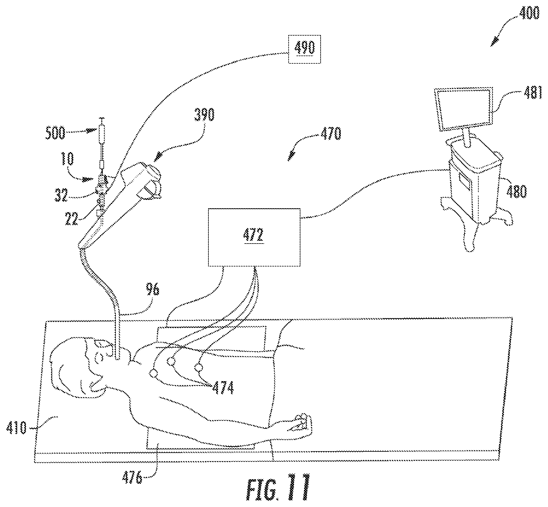
FIG. 11 is a perspective view of an exemplary surgical system including the catheter of FIG. 1.
DETAILED DESCRIPTION
This disclosure relates generally to catheters and methods for creating an electrical field adjacent targeted cells to allow molecules (e.g., genomic therapies) to pass through cell membranes or walls of target cells. The electrical fields may be configured to open pores in the cell walls of the target cells through electroporation to allow molecules to pass through the cell walls to enter the target cells. The catheter includes first and second electrodes that are positionable relative to one another such that an electrical field generated between the first and second electrodes opens pores in cell walls of target cells to permit molecules to enter the target cells. In addition, the catheter may include a lumen defined from a handle to a distal portion positioned adjacent target cells such that a molecule can be delivered to the target cells through the catheter as the electrical field is generated between the first and second electrodes.
Embodiments of the present disclosure are now described in detail with reference to the drawings in which like reference numerals designate identical or corresponding elements in each of the several views. As used herein, the term "clinician" refers to a doctor, a nurse, or any other care provider and may include support personnel. Throughout this description, the term "proximal" refers to the portion of the device or component thereof that is closest to the clinician and the term "distal" refers to the portion of the device or component thereof that is farthest from the clinician.
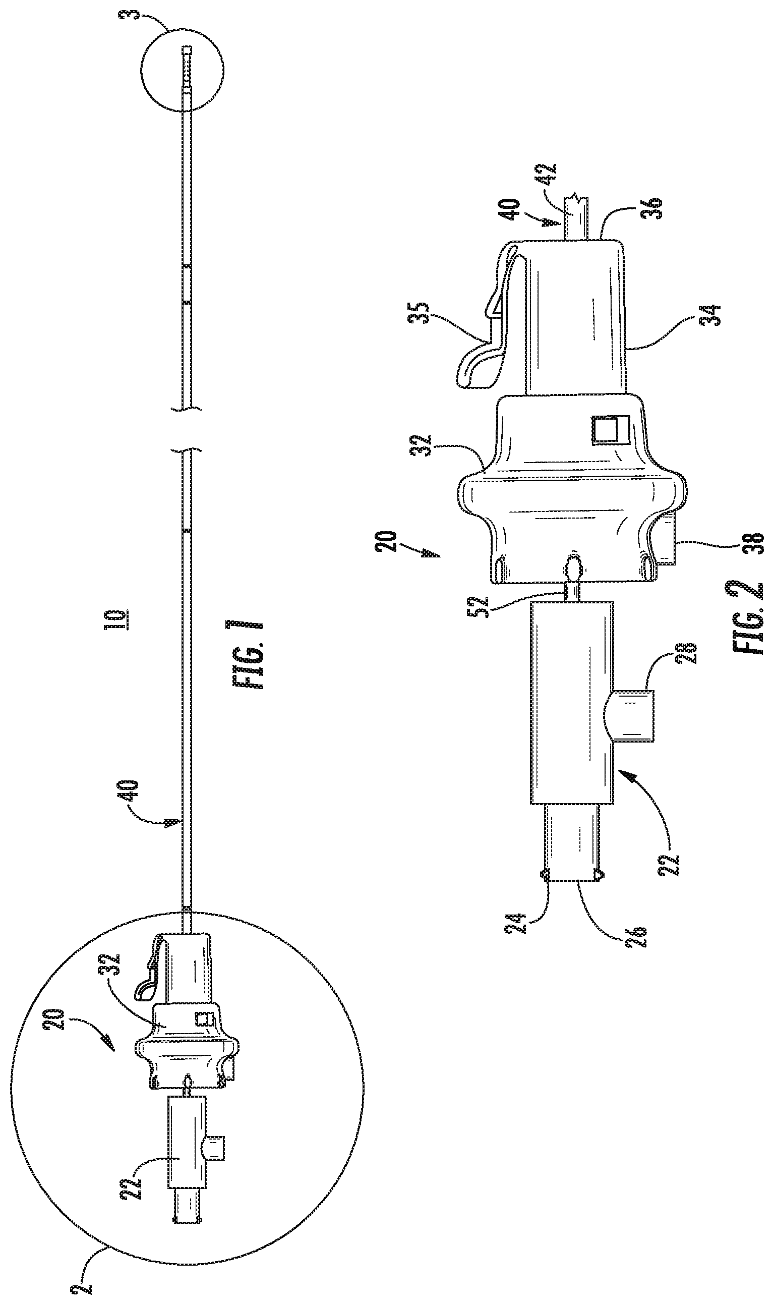
Referring now to FIG. 1, an exemplary catheter 10 provided in accordance with the present disclosure includes a handle assembly 20 and a tubular assembly 40. The handle assembly 20 is configured to be received in an access device or port (e.g., bronchoscope 390 (FIG. 10)) as detailed below.
With additional reference to FIG. 2, the handle assembly 20 includes a proximal handle 22 and a distal handle 32. The proximal handle 22 includes a proximally extending connector 24 that defines an opening 26 therethrough. The connector 24 may be a luer connector or any other suitable connector. The proximal handle 22 is mechanically coupled to an inner tubular member 52 of the tubular assembly 40 such that the inner tubular member 52 translates and/or rotates with the proximal handle 22 as described in detail below. The opening 26 is in communication with a lumen 56 (FIG. 4) defined by the inner tubular member 52. The proximal handle 22 also includes an electrical connector 28 for connecting to an external energy source (e.g., generator 490 (FIG. 11)) to receive a first energy potential as detailed below.
The distal handle 32 is coaxial with the proximal handle 22 and defines a passage 36 that allows the inner tubular member 52 to pass through the distal handle 32. The distal handle 32 includes a neck 34 that is configured to be received in an access device or port as detailed below. The neck 34 may include a tab 35 that is configured to engage the access device or port to longitudinally and/or rotatably secure the distal handle 32 to the access device or port. The distal handle 32 is coupled to an outer tubular member 42 of the tubular assembly 40 such that the outer tubular member 42 translates and/or rotates with the distal handle 32 as described in detail below. The distal handle 32 may include an electrical connector 38 for connecting to an external energy source (e.g., generator 490 (FIG. 11)) to receive a second energy potential different from the first energy potential as detailed below.
Referring now to FIG. 3, the tubular assembly 40 extends distally from the handle assembly 20 and includes the outer tubular member 42 and the inner tubular member 52. The outer tubular member 42 includes a first electrode 48 that is in electrical communication with the electrical connector 38 (FIG. 2) of the handle assembly 20. The outer tubular member 42 slidably receives the inner tubular member 52 within the channel 46 such that a distal portion of the inner tubular member 52 is extendable beyond the first electrode 48.
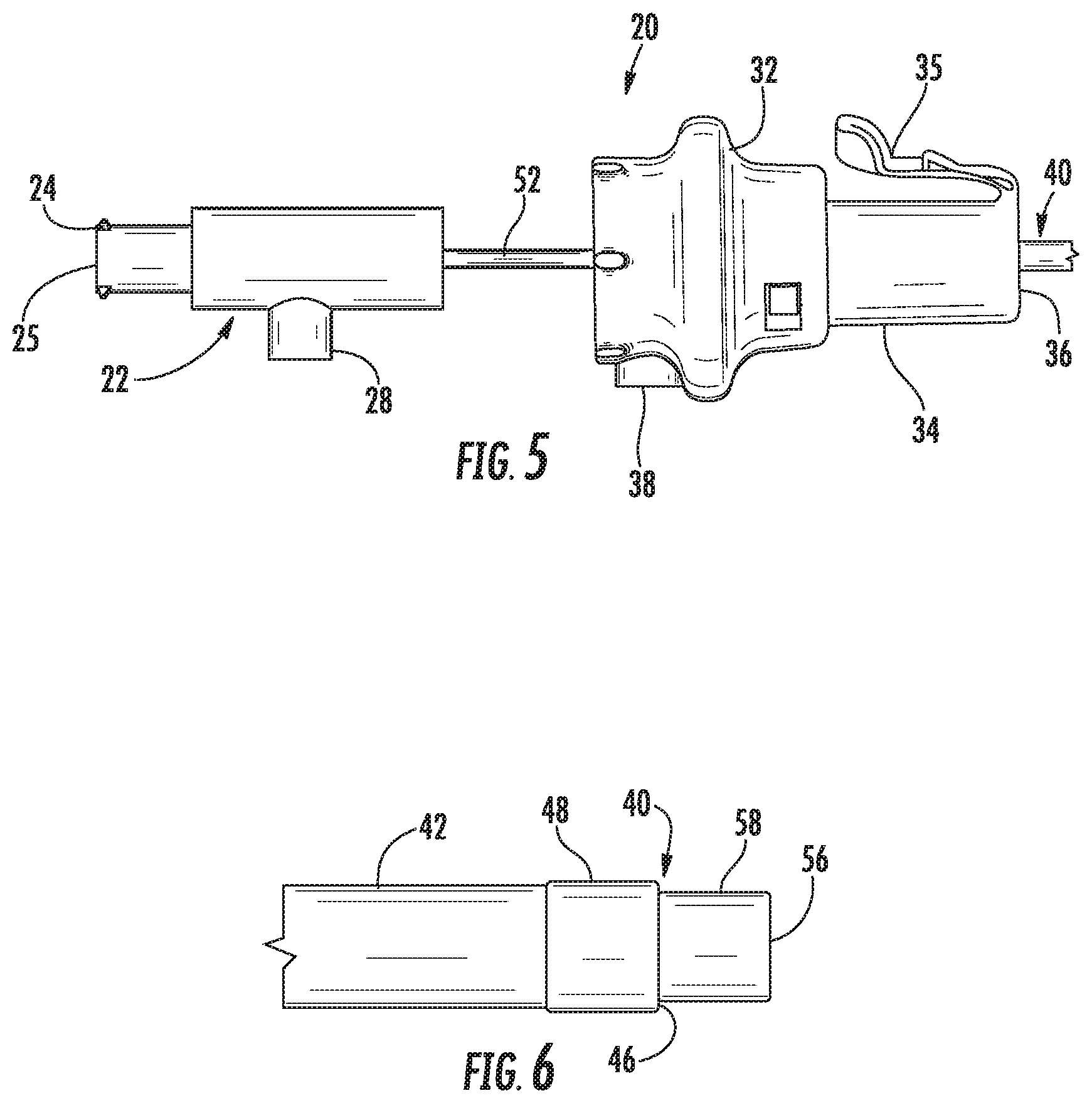
With additional reference to FIG. 4, the inner tubular member 52 (FIG. 3) defines a lumen 56 that is in communication with the opening 26 (FIG. 2) of the handle assembly 20 such that molecules can be delivered or a vacuum applied through the lumen 56 from the opening 26 without the need for an instrument or device to be passed through the opening 26. For example, a container (not shown) may be coupled to the connector 24 such that molecules from within the container flow through the lumen 56. It is also contemplated that an instrument or device or portion thereof (e.g., syringe 500 (FIG. 11)) can be passed entirely the tubular assembly 40.
The distal portion of the inner tubular member 52 may include holes 54 longitudinally and radially spaced apart from one another. The holes 54 can allow for molecules to flow from within the lumen 56 to tissue or cells surrounding the distal portion of the inner tubular member 52.
Referring briefly back to FIGS. 2 and 3, the catheter 10 has a first or extended configuration in which the second electrode 58 extends distally from the first electrode 48 such that a distal portion of the inner tubular member 52 is exposed between the first and second electrodes 48, 58. The position of the second electrode 58 relative to the first electrode 48 is affected by the position of the proximal handle portion 22 relative to the distal handle 32. It is contemplated that a surface of the inner tubular member 52 between the proximal handle 22 and the distal handle 32 may include markings indicating the distance that the second electrode 58 is extended from the first electrode 48. It is contemplated that the distance between the first and second electrodes 48, 58 affects the electric field generated by the catheter 10 as detailed below.
To generate the electric field between the first and second electrodes 48, 58, energy is supplied to the first and second electrodes 48, 58. This energy may be pulsed and is calibrated for the characteristics of the target cells such that the electric field generated between first and second electrodes 48, 58 creates or opens pores in the walls of the target cells such that molecules can enter the target cells. For a detailed description of electroporation of targeted cells reference can be made to U.S. Pat. Nos. 5,543,440 and 5,993,434.
With reference to FIGS. 5 and 6, the catheter 10 has a second or retracted configuration in which the second electrode 58 is positioned substantially within the channel 46 of the outer tubular member 42. As shown in FIG. 5, the proximal handle 22 is moved proximally from the extended configuration (FIG. 2) to retract or withdraw the second electrode 58.
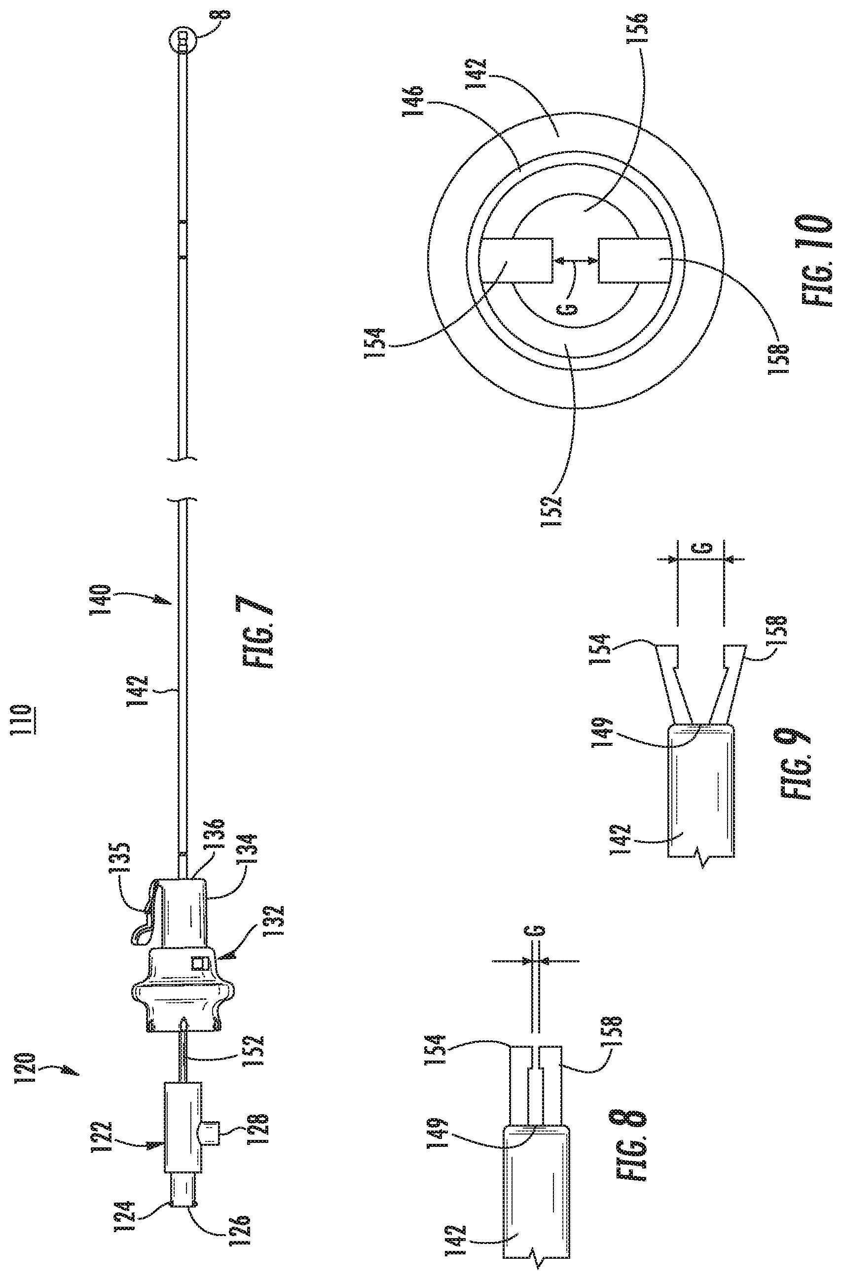
Referring now to FIGS. 7-9, another catheter 110 is provided in accordance with the present disclosure and includes a handle assembly 120 and a tubular assembly 40. Several elements of catheter 110 are similar to elements of catheter 10 detailed above and are represented with similar labels with a "1" preceding the previous label and will not be detailed herein below except for distinguishing catheter 110 from catheter 10.
The handle assembly 110 includes a proximal handle 122 and a distal handle 132 that are translatable along a common longitudinal axis relative to one another. The proximal handle 122 includes an electrical connector 128 that is configured to connect to an external energy source (e.g., generator 490 (FIG. 11)) as detailed below. The electrical connector 128 can receive a first energy potential and a second energy potential. An inner tubular member 152 of the tubular assembly 140 is mechanically coupled to the proximal handle 122.
With particular reference to FIG. 8, a distal portion of the inner tubular member 152 is extendable from a distal end 149 of an outer tubular member 142. The distal portion of the inner tubular member 152 includes a first electrode 154 and a second electrode 158 that define a gap "G" therebetween. The extent the first and second electrodes 154, 158 extend from the distal end 149 of the outer tubular member 142 and/or the gap "G" therebetween is affected by position of the proximal handle 122 relative to the distal handle 132.
The proximal and distal handles 122, 132 have a retracted configuration (not explicitly shown) in which the first and second electrodes 154, 158 are disposed within the distal end 149 of the outer tubular member 142. The proximal and distal handles 122, 132 have a first extended configuration in which the first and second electrodes 154, 158 extend from the distal end 149 of the outer tubular member 142 in which the gap "G" between the first and second electrodes 154, 158 has a first dimension as shown in FIG. 8. In addition, the proximal and distal handles 122, 132 may have a second extended configuration, such that the proximal handle 122 is closer to the distal handle 132 than in the first extended configuration, in which the first and second electrodes 154, 158, extend from the distal end 149 of the outer tubular member 142 and the gap "G" has a second dimension larger than the first dimension as shown in FIG. 9. It is contemplated that the first and second electrodes 154, 158 can be used to grasp tissue therebetween. In such embodiments, the first and second electrodes 154, 158 can be used to electroporate cells of the grasped tissue.
With additional reference to FIG. 10, the inner tubular member 152 defines a lumen 156 that is in communication with an opening 126 in the proximal handle 122 to allow an instrument and/or molecules to be inserted through the opening 126 and to exit the lumen 156 adjacent the first and second electrodes 154, 158.
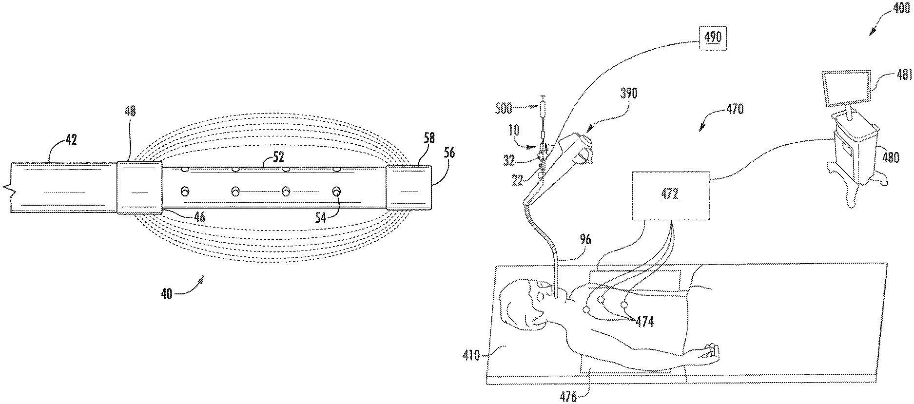
With reference to FIG. 11, an electromagnetic navigation (EMN) system 400 is provided in accordance with the present disclosure to position a distal portion of a catheter (e.g., catheter 10 or 110) adjacent target cells. FIG. 11 also depicts the catheter 10 for use with the EMN system 400; however, it is contemplated that other catheters (e.g., catheter 110) may also be used with EMN system 400. One such EMN system is the ELECTROMAGNETIC NAVIGATION BRONCHOSCOPY.RTM. system currently sold by Covidien LP. Among other tasks that may be performed using the EMN system 400 are planning a pathway to target cells, navigating a catheter guide assembly to the target cells, deploying an instrument adjacent or into the target cells to treat or capture the target cells, digitally marking the location of the target cells in a data file related to the planned pathway, and placing one or more echogenic markers at or around the target cells.
The EMN system 400 generally includes an operating table 410 configured to support a patient; a bronchoscope 390 configured for insertion through the patient's mouth and/or nose into the patient's airways; a tracking system 470 including a tracking module 472, a plurality of reference sensors 474, and an electromagnetic field generator 476; and a workstation 480 including software and/or hardware used to facilitate pathway planning, identification of target cells, navigation to target cells, and digitally marking the biopsy location.
The EMN system 400 is used to position a tubular member 96 of the bronchoscope adjacent target cells. It is contemplated that an extended working channel (EWC) (not explicitly shown) may be passed through the tubular member 96 to be positioned adjacent target cells. The EMN system 400 may include a locatable guide (LG) catheter (not shown) to position the EWC adjacent target cells. An example of a similar catheter guide assembly is currently marketed and sold by Covidien LP under the name EDGE.TM. Procedure Kits. For a more detailed description of the use of the catheter guide assembly reference is made to commonly-owned U.S. Patent Publication 2016/0000302, the entire contents of which are hereby incorporated by reference. Alternatively, the first and/or second electrode 48, 58 of the catheter 10 can include a sensor visible to the EMN system 400 that can be used to position the tubular member 96 adjacent target cells.
With the tubular member 96 positioned adjacent target cells, the catheter 10 is passed through the tubular member 96 until the outer tubular member 42 (FIG. 3) extends from the tubular member 96. Fluoroscopy can be used to confirm the location of the outer tubular member 42. With the outer tubular member 42 extended from the tubular member 96, a syringe 500 filled with a molecule (e.g., a genomic therapy, etc.) is connected to the connector 24 (FIG. 2). The syringe 500 may be configured to expel molecules into the opening 26 of the proximal handle 22 such that the molecules flow through the inner tubular member 52 and exits adjacent the second electrode 58. For example, the molecules may flow from the openings 54 in the distal portion of the inner tubular member 52. Alternatively, the syringe 500 may extend such that a distal portion of the syringe 500 is positioned adjacent the second electrode 58 (FIG. 3). It is contemplated that a distal portion of the syringe 500 may be positioned within the distal portion of the inner tubular member 52 or extend from the distal end of the inner tubular member 52.
A generator 490 is connected to the catheter 10 via electrical connectors 28, 38 (FIG. 2). With the generator 490 and the syringe 500 connected to the catheter 10 the proximal handle 22 is moved towards the distal handle 32 to extend the inner tubular member 52 such that the second electrode 58 is spaced apart from the first electrode 48. The position of the first and second electrodes 48, 58 may be verified using the EMN system as detailed above.
With the first and second electrodes 48, 58 positioned, the generator 490 is activated to generate an electric field between the first and second electrodes 48, 58. The electric field is configured to create electroporation in target cells such that molecules can pass through cell walls of the target cells. With the electric field active, the syringe 500 is extended to expel molecules from the inner tubular member 52 into the target cells. When the molecules are expelled, and after sufficient time to allow for the cells with the increased porosity size to take up the molecules, the generator 490 is deactivated and the catheter 10 is withdrawn or repositioned adjacent subsequent target cells. Upon deactivation the pores created in the cell walls is repaired by the cells. As the cell walls are repaired the molecules can be effectively trapped within the cell expediting treatment.
It is contemplated that the generator 490 can control the wave shape of the applied energy as well as the intensity and timing to allow for a series of pulses to be delivered to the target cells by the first and second electrodes. In addition, the generator 490 can receive electrocardiogram input, supplied through an EKG interface or another method, to synchronize energy delivery with the electrocardiogram input. For example, the energy deliver may be synchronized with an R wave signal to ensure that energy delivery is terminated during cardio repolarization/relative refractory or T-wave to reduce the potential for inducing ventricular fibrillation. In addition, intensity of the electric field generated during electroporation can reach several hundred volts per centimeter. The individual pulses of energy delivery may measure from microseconds to milliseconds in length, keeping the total application time under about one second. The shaping of these pulses may be square or sinusoidal; however, saw tooth waves have been contemplated.
While the use of the catheter 10 is detailed herein for use in the airway of a patient, it is contemplated that the catheter 10 may be used in a variety of surgical procedures utilizing elongated surgical instruments with extended working channels. For example, the catheter 10 may be used during various endovascular procedures such as cardiac interventions, general vascular interventional procedures, cerebral interventions, etc. These procedures may include, but are not limited to, balloon dilations, stent placements, percutaneous valve replacement, and percutaneous valve repair, pacing lead placement, cardiac ablation procedures, and electrical mapping procedures.
While several embodiments of the disclosure have been shown in the drawings, it is not intended that the disclosure be limited thereto, as it is intended that the disclosure be as broad in scope as the art will allow and that the specification be read likewise. Any combination of the above embodiments is also envisioned and is within the scope of the appended claims. Therefore, the above description should not be construed as limiting, but merely as exemplifications of particular embodiments. Those skilled in the art will envision other modifications within the scope of the claims appended hereto.
* * * * *
References
D00000
D00001
D00002
D00003
D00004
D00005
XML
uspto.report is an independent third-party trademark research tool that is not affiliated, endorsed, or sponsored by the United States Patent and Trademark Office (USPTO) or any other governmental organization. The information provided by uspto.report is based on publicly available data at the time of writing and is intended for informational purposes only.
While we strive to provide accurate and up-to-date information, we do not guarantee the accuracy, completeness, reliability, or suitability of the information displayed on this site. The use of this site is at your own risk. Any reliance you place on such information is therefore strictly at your own risk.
All official trademark data, including owner information, should be verified by visiting the official USPTO website at www.uspto.gov. This site is not intended to replace professional legal advice and should not be used as a substitute for consulting with a legal professional who is knowledgeable about trademark law.