Slotted sleeve neurostimulation device
Nageri , et al. October 27, 2
U.S. patent number 10,814,127 [Application Number 15/424,481] was granted by the patent office on 2020-10-27 for slotted sleeve neurostimulation device. This patent grant is currently assigned to BOSTON SCIENTIFIC NEUROMODULATION CORPORATION. The grantee listed for this patent is Boston Scientific Neuromodulation Corporation. Invention is credited to Ranjan Krishna Mukhari Nageri, Tiffany Shen.


| United States Patent | 10,814,127 |
| Nageri , et al. | October 27, 2020 |
Slotted sleeve neurostimulation device
Abstract
An electrical stimulation lead for a target nerve includes a sleeve having an inner surface and an outer surface, the inner surface defines a nerve channel. A longitudinal slit extends from the outer surface to the nerve channel and along an entire length of the sleeve. A width of the slit retains the target nerve within the nerve channel when the sleeve is closed and releases the target nerve when open. A plurality of electrodes are disposed on the inner surface of the sleeve. A flexible transition element electrically couples a lead body to the plurality of electrodes. Upper and lower sections of the sleeve rotates about a common hinge line (e.g., like a clam shell) located directly opposite the longitudinal slit. The material along the common hinge line remains "elastic" when the sleeve is moved from closed to open, and vice-versa.
| Inventors: | Nageri; Ranjan Krishna Mukhari (Valencia, CA), Shen; Tiffany (Laguna Niguel, CA) | ||||||||||
|---|---|---|---|---|---|---|---|---|---|---|---|
| Applicant: |
|
||||||||||
| Assignee: | BOSTON SCIENTIFIC NEUROMODULATION
CORPORATION (Valencia, CA) |
||||||||||
| Family ID: | 1000005140031 | ||||||||||
| Appl. No.: | 15/424,481 | ||||||||||
| Filed: | February 3, 2017 |
Prior Publication Data
| Document Identifier | Publication Date | |
|---|---|---|
| US 20170224982 A1 | Aug 10, 2017 | |
Related U.S. Patent Documents
| Application Number | Filing Date | Patent Number | Issue Date | ||
|---|---|---|---|---|---|
| 62292093 | Feb 5, 2016 | ||||
| Current U.S. Class: | 1/1 |
| Current CPC Class: | A61N 1/0558 (20130101); A61N 1/0556 (20130101); A61N 1/3605 (20130101) |
| Current International Class: | A61N 1/05 (20060101); A61N 1/36 (20060101) |
References Cited [Referenced By]
U.S. Patent Documents
| 3769984 | November 1973 | Muench |
| 3941136 | March 1976 | Bucalo |
| 4033357 | July 1977 | Helland et al. |
| 4135518 | January 1979 | Dutcher |
| 4257428 | March 1981 | Barton et al. |
| 4301815 | November 1981 | Doring |
| 4409994 | October 1983 | Doring |
| 4475560 | October 1984 | Tarjan et al. |
| 4506679 | March 1985 | Mann |
| 4542753 | September 1985 | Brenman et al. |
| 4585005 | April 1986 | Lue et al. |
| 4628944 | December 1986 | MacGregor et al. |
| 4702254 | October 1987 | Zabara |
| 4716888 | January 1988 | Wesner |
| 4722353 | February 1988 | Sluetz |
| 4796643 | January 1989 | Nakazawa et al. |
| 4867164 | September 1989 | Zabara |
| 4920979 | May 1990 | Bullara |
| 4934368 | June 1990 | Lynch |
| 4957118 | September 1990 | Erlebacher |
| 5025807 | June 1991 | Zabara |
| 5095905 | March 1992 | Klepinski |
| 5139539 | August 1992 | Haynes, Jr. |
| 5143067 | September 1992 | Rise et al. |
| 5193539 | March 1993 | Schulman et al. |
| 5193540 | March 1993 | Schulman et al. |
| 5239540 | August 1993 | Rovira et al. |
| 5251634 | October 1993 | Weinberg |
| 5257634 | November 1993 | Kroll |
| 5282468 | February 1994 | Klepinski |
| 5312439 | May 1994 | Loeb |
| 5314457 | May 1994 | Jeutter et al. |
| 5324322 | June 1994 | Grill et al. |
| 5324327 | June 1994 | Cohen |
| 5376108 | December 1994 | Collins et al. |
| 5405367 | April 1995 | Schulman et al. |
| 5433735 | July 1995 | Zanakis et al. |
| 5439938 | August 1995 | Synder et al. |
| 5454840 | October 1995 | Krakovsky et al. |
| 5480420 | January 1996 | Hoegnelid et al. |
| 5487756 | January 1996 | Kallesoe et al. |
| 5531781 | July 1996 | Alferness et al. |
| 5571118 | November 1996 | Boutos |
| 5741319 | April 1998 | Woloszko et al. |
| 5755762 | May 1998 | Bush |
| 5775331 | July 1998 | Raymond et al. |
| 5876399 | March 1999 | Chia et al. |
| 5919220 | July 1999 | Stieglitz et al. |
| 5922015 | July 1999 | Schaldach et al. |
| 5938584 | August 1999 | Ardito et al. |
| 6051017 | April 2000 | Loeb et al. |
| 6058332 | May 2000 | Dahl |
| 6061596 | May 2000 | Richmond et al. |
| 6151526 | November 2000 | Tziviskos |
| 6175710 | January 2001 | Kamaji et al. |
| 6175764 | January 2001 | Loeb et al. |
| 6181965 | January 2001 | Loeb et al. |
| 6181969 | January 2001 | Gord |
| 6181973 | January 2001 | Ceron et al. |
| 6185452 | February 2001 | Schulman et al. |
| 6185455 | February 2001 | Loeb et al. |
| 6188932 | February 2001 | Lindegren |
| 6201994 | March 2001 | Warman et al. |
| 6214032 | April 2001 | Loeb et al. |
| 6224450 | May 2001 | Norton |
| 6271094 | August 2001 | Boyd et al. |
| 6278897 | August 2001 | Rutten et al. |
| 6292703 | September 2001 | Meier et al. |
| 6295944 | October 2001 | Lovett |
| 6308105 | October 2001 | Duysens et al. |
| 6315721 | November 2001 | Schulman et al. |
| 6364278 | April 2002 | Lin et al. |
| 6391985 | May 2002 | Goode et al. |
| 6456866 | September 2002 | Tyler et al. |
| 6463335 | October 2002 | Munch et al. |
| 6516227 | February 2003 | Meadows et al. |
| 6582441 | June 2003 | He et al. |
| 6584363 | June 2003 | Heil, Jr. et al. |
| 6609029 | August 2003 | Mann et al. |
| 6609032 | August 2003 | Woods et al. |
| 6643546 | November 2003 | Mathis et al. |
| 6650943 | November 2003 | Whitehurst et al. |
| 6735474 | May 2004 | Loeb et al. |
| 6741892 | May 2004 | Meadows et al. |
| 6788975 | September 2004 | Whitehurst et al. |
| 7003352 | February 2006 | Whitehurst |
| 7006875 | February 2006 | Kuzma et al. |
| 7203548 | April 2007 | Whitehurst et al. |
| 7244150 | July 2007 | Brase et al. |
| 7248930 | July 2007 | Woloszko et al. |
| 7292890 | November 2007 | Whitehurst et al. |
| 7437193 | October 2008 | Parramon et al. |
| 7450997 | November 2008 | Pianca et al. |
| 7460913 | December 2008 | Kuzma et al. |
| 7584004 | September 2009 | Caparso et al. |
| 7596414 | September 2009 | Whitehurst et al. |
| 7610103 | October 2009 | Whitehurst et al. |
| 7672734 | March 2010 | Anderson et al. |
| 7706892 | April 2010 | Colvin et al. |
| 7761165 | July 2010 | He et al. |
| 7783359 | August 2010 | Meadows |
| 7783362 | August 2010 | Whitehurst et al. |
| 7792590 | September 2010 | Pianca et al. |
| 7809446 | October 2010 | Meadows |
| 7840279 | November 2010 | He |
| 7949395 | May 2011 | Kuzma |
| 7953498 | May 2011 | Carbunaru et al. |
| 7974706 | July 2011 | Moffitt et al. |
| 8019443 | September 2011 | Schleicher et al. |
| 8155757 | April 2012 | Neisz et al. |
| 8175710 | May 2012 | He |
| 8224450 | July 2012 | Brase |
| 8271094 | September 2012 | Moffitt et al. |
| 8295944 | October 2012 | Howard et al. |
| 8364278 | January 2013 | Pianca et al. |
| 8391985 | March 2013 | McDonald |
| 8483237 | July 2013 | Zimmermann et al. |
| 8594805 | November 2013 | Hincapie Ordonez et al. |
| 8612025 | December 2013 | Neisz et al. |
| 8688235 | April 2014 | Pianca et al. |
| 8718790 | May 2014 | Pianca |
| 8768488 | July 2014 | Barker |
| 8818524 | August 2014 | Hincapie Ordonez et al. |
| 8831742 | September 2014 | Pianca et al. |
| 8849422 | September 2014 | Pianca |
| 8934992 | January 2015 | Johnson et al. |
| 2003/0040785 | February 2003 | Maschino et al. |
| 2003/0045919 | March 2003 | Swoyer et al. |
| 2003/0074039 | April 2003 | Puskas |
| 2003/0078623 | April 2003 | Weinberg et al. |
| 2003/0114905 | June 2003 | Kuzma |
| 2003/0199938 | October 2003 | Smits et al. |
| 2003/0236558 | December 2003 | Whitehurst et al. |
| 2004/0010303 | January 2004 | Bolea et al. |
| 2004/0034401 | February 2004 | Dahlberg et al. |
| 2004/0049240 | March 2004 | Gerber |
| 2004/0059392 | March 2004 | Parramon et al. |
| 2004/0111139 | June 2004 | McCreery |
| 2004/0230280 | November 2004 | Cates et al. |
| 2005/0010265 | January 2005 | Baru Fassio et al. |
| 2005/0065589 | March 2005 | Schneider et al. |
| 2005/0177220 | August 2005 | Iaizzo et al. |
| 2005/0182472 | August 2005 | Wahlstrom et al. |
| 2006/0161204 | July 2006 | Colvin et al. |
| 2006/0184204 | August 2006 | He |
| 2006/0212075 | September 2006 | Marnfeldt |
| 2006/0241737 | October 2006 | Tockman et al. |
| 2006/0282145 | December 2006 | Caparso et al. |
| 2007/0150036 | June 2007 | Anderson |
| 2007/0219595 | September 2007 | He |
| 2008/0046055 | February 2008 | Durand |
| 2008/0071320 | March 2008 | Brase |
| 2009/0187222 | July 2009 | Barker |
| 2009/0210042 | August 2009 | Kowalczewski |
| 2009/0276021 | November 2009 | Meadows et al. |
| 2009/0287271 | November 2009 | Blum et al. |
| 2009/0287272 | November 2009 | Kokones et al. |
| 2009/0287273 | November 2009 | Carlton et al. |
| 2009/0287467 | November 2009 | Sparks et al. |
| 2010/0049276 | February 2010 | Blum et al. |
| 2010/0076535 | March 2010 | Pianca et al. |
| 2010/0168831 | July 2010 | Korivi |
| 2010/0241207 | September 2010 | Bluger |
| 2010/0268298 | October 2010 | Moffitt et al. |
| 2010/0298916 | November 2010 | Rabischong et al. |
| 2010/0312320 | December 2010 | Faltys |
| 2011/0004267 | January 2011 | Meadows et al. |
| 2011/0005069 | January 2011 | Pianca |
| 2011/0078900 | April 2011 | Pianca et al. |
| 2011/0130803 | June 2011 | McDonald |
| 2011/0130817 | June 2011 | Chen |
| 2011/0130818 | June 2011 | Chen |
| 2011/0238129 | September 2011 | Moffitt et al. |
| 2011/0313500 | December 2011 | Barker et al. |
| 2012/0016378 | January 2012 | Pianca et al. |
| 2012/0046710 | February 2012 | Digiore et al. |
| 2012/0071949 | March 2012 | Pianca et al. |
| 2012/0165911 | June 2012 | Pianca |
| 2012/0185027 | July 2012 | Pianca et al. |
| 2012/0197375 | August 2012 | Pianca et al. |
| 2012/0203320 | August 2012 | Digiore et al. |
| 2012/0203321 | August 2012 | Moffitt et al. |
| 2012/0277819 | November 2012 | Cowley |
| 2012/0316615 | December 2012 | Digiore et al. |
| 2013/0023974 | January 2013 | Amrani |
| 2013/0105071 | May 2013 | Digiore et al. |
| 2013/0172973 | July 2013 | Tockman et al. |
| 2013/0197424 | August 2013 | Bedenbaugh |
| 2013/0197602 | August 2013 | Pianca et al. |
| 2013/0261684 | October 2013 | Howard |
| 2013/0317518 | November 2013 | Govea |
| 2013/0317587 | November 2013 | Barker |
| 2013/0325091 | December 2013 | Pianca et al. |
| 2014/0039587 | February 2014 | Romero |
| 2014/0074213 | March 2014 | Neisz et al. |
| 2014/0128950 | May 2014 | Thota |
| 2014/0228905 | August 2014 | Bolea |
| 2014/0277284 | September 2014 | Chen et al. |
| 2014/0353001 | December 2014 | Romero et al. |
| 2014/0358207 | December 2014 | Romero |
| 2014/0358209 | December 2014 | Romero et al. |
| 2014/0358210 | December 2014 | Howard et al. |
| 2015/0018915 | January 2015 | Leven |
| 2015/0021817 | January 2015 | Romero et al. |
| 2015/0045864 | February 2015 | Howard |
| 2015/0066120 | March 2015 | Govea |
| 2015/0119965 | April 2015 | Govea |
| 2015/0151113 | June 2015 | Govea et al. |
| 2015/0202433 | July 2015 | Franke et al. |
| 2015/0202446 | July 2015 | Franke et al. |
| 2015/0366467 | December 2015 | De Kock et al. |
| 2017/0224982 | August 2017 | Nageri et al. |
| 98/37926 | Sep 1998 | WO | |||
| 98/43701 | Oct 1998 | WO | |||
| 2008019483 | Feb 2008 | WO | |||
| 2008048471 | Apr 2008 | WO | |||
| 2013188871 | Dec 2013 | WO | |||
Other References
|
Rattay, F., "Analysis of Models for External Stimulation of Axons," IEEE Transactions on Biomedical Engineering, BME-33(10): 974-977, 1986. cited by applicant . U.S. Appl. No. 15/601,838, filed May 22, 2017. cited by applicant . U.S. Appl. No. 15/608,573, filed May 30, 2017. cited by applicant . U.S. Appl. No. 62/429,650, filed Dec. 2, 2016. cited by applicant . U.S. Appl. No. 15/656,734, filed Jul. 21, 2017. cited by applicant . Rozman et al., "Selective Stimulation of Autonomic Nerves and Recording of Electroneurograms in a Canine Model," Artificial Organs, 21(8): 592-596, 2008. cited by applicant . Polasek et al., "Stimulation Stability and Selectivity of Chronically Implanted Multicontact Nerve Cuff Electrodes in the Human Upper Extremity," IEEE Transactions on Neural Systems and Rehabilitation Engineering, vol. 17, No. 5, 428-437, Oct. 2009. cited by applicant . Plachta et al., "Blood pressure control with selective vagal nerve stimulation and minimal side effects," J. Neural Eng. 11 (2014) 036011 (15pp), 2014. cited by applicant . U.S. Appl. No. 12/177,823, Entitled: Lead With Transition and Methods of Manufacture and Use, Inventor: Pianca et al., filed Jul. 22, 2008, 22 pages. cited by applicant . U.S. Appl. No. 13/750,725, Entitled: Systems and Methods for Identifying the Circumferential Positioning of Electrodes of Leads for Electrical Stimulation Systems, Inventor: Pianca et al., filed Jan. 25, 2013, 36 pages. cited by applicant . U.S. Appl. No. 62/292,093, Entitled: Slotted Sleeve Neurostimulation Device, Inventor: Ranjan Krishna Mukhari Nageri et al., filed Feb. 5, 2016, 32 pages. cited by applicant . U.S. Appl. No. 62/297,616, Entitled: Electrical Stimulation Cuff Devices and Systems, Inventor: Ranjan Mukhari Nageri et al., filed Feb. 19, 2016, 34 pages. cited by applicant . U.S. Appl. No. 15/436,544, Entitled: Electrical Stimulation Cuff Devices and Systems, Inventor: Govea et al., filed Feb. 17, 2017, 31 pages. cited by applicant. |
Primary Examiner: Holmes; Rex R
Assistant Examiner: Ghand; Jennifer L
Attorney, Agent or Firm: Lowe Graham Jones PLLC Black; Bruce E.
Parent Case Text
CROSS-REFERENCE TO RELATED APPLICATIONS
This application claims the benefit under 35 U.S.C. .sctn. 119(e) of U.S. Provisional Patent Application Ser. No. 62/292,093, filed Feb. 5, 2016, which is incorporated herein by reference.
Claims
What is claimed as new and desired to be protected by Letters Patent of the United States is:
1. An electrical stimulation lead for stimulating a target nerve, the electrical stimulation lead comprising: an elongated sleeve having a first portion and a second portion, the first portion hingedly coupled to the second portion, the elongated sleeve having an inner surface that continually extends from the first portion to the second portion and an outer surface that continually extends from the first portion to the second portion, the inner surface defining a nerve channel to receive the target nerve, the elongated sleeve further having a longitudinal slit extending from the outer surface to the nerve channel, the longitudinal slit extending along an entire length of the elongated sleeve, wherein a section of the first portion hingedly moves relative to a section of the second portion to receive the target nerve into the nerve channel, wherein the elongated sleeve includes tapered end portions; a plurality of electrodes disposed on the inner surface of the elongated sleeve; a lead body; a plurality of conductors extending along the lead body; and a ribbon cable extending from the elongated sleeve and attached to the lead body to electrically couple the conductors extending along the lead body to the plurality of electrodes, wherein the ribbon cable includes a bellowed portion for strain relief.
2. The electrical stimulation lead of claim 1, wherein the section of the first portion rotates relative to the section of the second portion relative to a common hinge line located opposite the longitudinal slit.
3. The electrical stimulation lead of claim 2, wherein material along the common hinge line remains in a mechanically elastic range when the elongated sleeve is moved from a closed position to an open position.
4. The electrical stimulation lead of claim 1, further comprising at least one suture tab extending from the elongated sleeve.
5. The electrical stimulation lead of claim 4, wherein the at least one suture tab includes a pre-made suture hole.
6. The electrical stimulation lead of claim 4, wherein the at least one suture tab includes a suture slit that cooperates with the longitudinal slit of the elongated sleeve.
7. The electrical stimulation lead of claim 1, wherein the plurality of electrodes have a shape complementary to the inner surface of the elongated sleeve.
8. The electrical stimulation lead of claim 1, wherein a width of the longitudinal slit is configured to retain the target nerve within the nerve channel when the elongated sleeve is in a closed position and configured to receive or release the target nerve when the elongated sleeve is in an open position.
9. The electrical stimulation lead of claim 1, wherein the plurality of electrodes are arranged in two or more parallel rows or columns.
10. The electrical stimulation lead of claim 1, wherein an inward facing surface of each of the electrodes is flush with the inner surface of the elongated sleeve.
11. The electrical stimulation lead of claim 1, wherein an inward facing surface of each of the electrodes is recessed relative to the inner surface of the elongated sleeve.
12. An electrical stimulation system comprising: the electrical stimulation lead of claim 1; a control module coupleable to the electrical stimulation lead, the control module comprising a housing, and an electronic subassembly disposed in the housing; and a connector for receiving the electrical stimulation lead, the connector having a proximal end, a distal end, and a longitudinal length, the connector comprising a connector housing defining a port at the distal end of the connector, the port configured and arranged for receiving a proximal end of the lead body of the electrical stimulation lead, and a plurality of connector contacts disposed in the connector housing, a plurality of connector contacts configured and arranged to couple to at least one of a plurality of terminals disposed on the proximal end of the lead body of the electrical stimulation lead.
13. The electrical stimulation system of claim 12, further comprising a lead extension coupleable to both the electrical stimulation lead and the control module.
14. The electrical stimulation system of claim 12, further comprising at least one suture tab extending from the elongated sleeve.
15. The electrical stimulation system of claim 14, wherein the at least one suture tab includes a suture slit that cooperates with the longitudinal slit of the elongated sleeve, wherein the suture slit separates one of the at least one suture tab into two separate portions that are each attached to a different portion of the elongated sleeve and align with each other when the elongated sleeve is in a closed position.
16. An electrical stimulation lead for stimulating a target nerve, the electrical stimulation lead comprising: an elongated sleeve having a first portion and a second portion, the first portion hingedly coupled to the second portion, the elongated sleeve having an inner surface that continually extends from the first portion to the second portion and an outer surface that continually extends from the first portion to the second portion, the inner surface defining a nerve channel to receive the target nerve, the elongated sleeve further having a longitudinal slit extending from the outer surface to the nerve channel, the longitudinal slit extending along an entire length of the elongated sleeve, wherein a section of the first portion hingedly moves relative to a section of the second portion to receive the target nerve into the nerve channel, wherein the elongated sleeve includes tapered end portions; a plurality of electrodes disposed on the inner surface of the elongated sleeve; a lead body; a plurality of conductors extending along the lead body; a ribbon cable extending from the elongated sleeve and attached to the lead body to electrically couple the conductors extending along the lead body to the plurality of electrodes; and at least one suture tab extending from the elongated sleeve, wherein the at least one suture tab includes a suture slit that cooperates with the longitudinal slit of the elongated sleeve, wherein the suture slit separates at least one of the at least one suture tab into two separate portions that are each attached to a different portion of the elongated sleeve and align with each other when the elongated sleeve is in a closed position.
17. The electrical stimulation lead of claim 16, wherein each of the two separate portions of the at least one of the at least one suture tab includes a suture hole.
18. The electrical stimulation lead of claim 17, wherein the suture holes of the two separate portions align with each other when the elongated sleeve is in a closed position.
19. An electrical stimulation system comprising: the electrical stimulation lead of claim 16; a control module coupleable to the electrical stimulation lead, the control module comprising a housing, and an electronic subassembly disposed in the housing; and a connector for receiving the electrical stimulation lead, the connector having a proximal end, a distal end, and a longitudinal length, the connector comprising a connector housing defining a port at the distal end of the connector, the port configured and arranged for receiving a proximal end of the lead body of the electrical stimulation lead, and a plurality of connector contacts disposed in the connector housing, a plurality of connector contacts configured and arranged to couple to at least one of a plurality of terminals disposed on the proximal end of the lead body of the electrical stimulation lead.
20. The electrical stimulation system of claim 19, wherein the ribbon cable includes a bellowed portion for strain relief.
Description
FIELD
The present invention is directed to the area of implantable electrical stimulation devices and methods of making and implanting the same. The present invention is also directed to slotted sleeve electrical stimulation devices, as well as methods of making and implanting the same.
BACKGROUND
Implantable electrical stimulation systems have proven therapeutic in a variety of diseases and disorders. For example, spinal cord stimulation systems have been used as a therapeutic modality for the treatment of chronic pain syndromes. Peripheral nerve stimulation has been used to treat chronic pain syndrome and incontinence, with a number of other applications under investigation. Functional electrical stimulation systems have been applied to restore some functionality to paralyzed extremities in spinal cord injury patients. Stimulation of the brain, such as deep brain stimulation, can be used to treat a variety of diseases or disorders.
Stimulators have been developed to provide therapy for a variety of treatments. A stimulator can include a control module (with a pulse generator), one or more leads, and an array of stimulator electrodes on each lead. The stimulator electrodes are in contact with or near the nerves, muscles, or other tissue to be stimulated. The pulse generator in the control module generates electrical pulses that are delivered by the electrodes to body tissue.
BRIEF SUMMARY
In one embodiment, an electrical stimulation lead for stimulating a target nerve includes an elongated sleeve having an inner surface and an outer surface, the inner surface defining a nerve channel, the sleeve further having a longitudinal slit extending from the outer surface to the nerve channel and further extending along an entire length of the sleeve. The lead further includes at least one suture tab having opposing surfaces defined by the longitudinal slit and the suture tab extends from the sleeve. The electrical stimulation lead further includes a plurality of electrodes disposed on the inner surface of the sleeve; a lead body; and a flexible transition element configured to electrically couple the lead body to the plurality of electrodes.
In at least some embodiments, the plurality of electrodes have a shape complementary to the inner surface of the sleeve. For opening and closing in the clam shell manner, the sleeve includes an elastic hinge line that cooperates with the longitudinal slit when the sleeve is manipulated to receive the target into the nerve channel. A width of the slit operates to retain the target nerve within the nerve channel when the sleeve is in a closed position and operates to receive or release the target nerve when the sleeve is in an open position (e.g., in the clam shell manner).
In at least some embodiments, the sleeve includes tapered end portions. The transition element takes the form of a ribbon cable having one or more bellowed portions for strain relief.
In another embodiment, an electrical stimulation system includes the electrical stimulation lead described above and further includes a control module and a connector. The control module is coupled to the electrical stimulation lead and includes a housing and an electronic subassembly disposed in the housing. The connector receives the electrical stimulation lead, and includes a proximal end, a distal end, and a longitudinal length. The connector further includes a connector housing that defines a port at the distal end of the connector, such that the port receives the proximal end of the lead body of the electrical stimulation lead. A plurality of connector contacts disposed in the connector housing couple to at least one of a plurality of terminals disposed on a proximal end of the lead body of the electrical stimulation lead. In at least some embodiments, a lead extension couples to both the electrical stimulation lead and the control module.
In yet another embodiment, an electrical stimulation lead for stimulating a target nerve includes an elongated sleeve having a first portion and a second portion, in which the first portion is hingedly coupled to the second portion. The sleeve has an inner surface that continually extends from the first portion to the second portion and an outer surface that continually extends from the first portion to the second portion. The inner surface defines a nerve channel for receiving the target nerve. The sleeve further includes a longitudinal slit extending from the outer surface to the nerve channel and also extending along an entire length of the sleeve. A section of the first portion hingedly moves relative to a section of the second portion, such that the sleeve opens in a clam shell manner, to receive the target nerve into the nerve channel. The sleeve also has tapered end portions. The electrical stimulation lead further includes a plurality of electrodes disposed on the inner surface of the sleeve; a lead body; and a ribbon cable that electrically couples the lead body to the plurality of electrodes.
In at least some embodiments, the section of the first portion rotates relative to the section of the second portion relative to a common hinge line (e.g., like a clam shell) located opposite the longitudinal slit. The material along the common hinge line remains in a mechanically elastic range when the sleeve is moved from a closed position to an open position.
In at least some embodiments, the lead further includes at least one suture tab having opposing surfaces defined by the longitudinal slit and the suture tab extends from the sleeve. The ribbon cable may include one or more bellowed portions for strain relief.
In further embodiments, an electrical stimulation system includes the electrical stimulation lead of claim described above, a control module and a connector. The control module is coupled to the electrical stimulation lead and includes a housing and an electronic subassembly disposed in the housing. The connector receives the electrical stimulation lead. The connector includes a proximal end, a distal end, and a longitudinal length. The connector further includes a connector housing that defines a port at the distal end of the connector. The port receives a proximal end of the lead body of the electrical stimulation lead. A plurality of connector contacts are disposed in the connector housing and operate to couple with at least one of a plurality of terminals disposed on the proximal end of the lead body. At least in some embodiments, the electrical stimulation system also includes a lead extension coupleable to both the electrical stimulation lead and the control module.
BRIEF DESCRIPTION OF THE DRAWINGS
Non-limiting and non-exhaustive embodiments of the present invention are described with reference to the following drawings. In the drawings, like reference numerals refer to like parts throughout the various figures unless otherwise specified.
For a better understanding of the present invention, reference will be made to the following Detailed Description, which is to be read in association with the accompanying drawings, wherein:
FIG. 1 is a schematic view of one embodiment of an electrical stimulation system that includes a lead electrically coupled to a control module according to an embodiment of the present invention;
FIG. 2A is a schematic view of one embodiment of the control module of FIG. 1 configured and arranged to electrically couple to an elongated device according to an embodiment of the present invention;
FIG. 2B is a schematic view of one embodiment of a lead extension configured and arranged to electrically couple the elongated device of FIG. 2A to the control module of FIG. 1 according to an embodiment of the present invention;
FIG. 3 is a schematic perspective view of a distal end portion of a lead that includes a slotted sleeve stimulation device according to an embodiment of the present invention;
FIG. 4 is a schematic, perspective, close-up view of the slotted sleeve stimulation device of FIG. 3 according to an embodiment of the present invention;
FIG. 5 is a schematic, perspective, close-up view of a slotted sleeve stimulation device with suture blocks according to another embodiment of the present invention; and
FIG. 6 is a schematic overview of one embodiment of components of an electrical stimulation arrangement according to an embodiment of the present invention.
DETAILED DESCRIPTION
The present invention is directed to the area of implantable electrical stimulation systems and methods of making and using the systems. The present invention is also directed to implantable sleeve electrical stimulation devices, as well as methods of making and using the same.
Suitable implantable electrical stimulation systems include, but are not limited to, a least one lead with one or more electrodes disposed along a distal end of the lead. Leads include, for example, percutaneous leads, paddle leads, and cuff leads. Examples of electrical stimulation systems with leads are found in, for example, U.S. Pat. Nos. 6,181,969; 6,516,227; 6,609,029; 6,609,032; 6,741,892; 7,203,548; 7,244,150; 7,450,997; 7,596,414; 7,610,103; 7,672,734; 7,761,165; 7,783,359; 7,792,590; 7,809,446; 7,949,395; 7,974,706; 6,175,710; 6,224,450; 6,271,094; 6,295,944; 6,364,278; and 6,391,985; U.S. Patent Applications Publication Nos. 2007/0150036; 2009/0187222; 2009/0276021; 2010/0076535; 2010/0268298; 2011/0004267; 2011/0078900; 2011/0130817; 2011/0130818; 2011/0238129; 2011/0313500; 2012/0016378; 2012/0046710; 2012/0071949; 2012/0165911; 2012/0197375; 2012/0203316; 2012/0203320; 2012/0203321; 2012/0316615; and 2013/0105071; and U.S. patent application Ser. Nos. 12/177,823 and 13/750,725, all of which are incorporated by reference in their entireties.
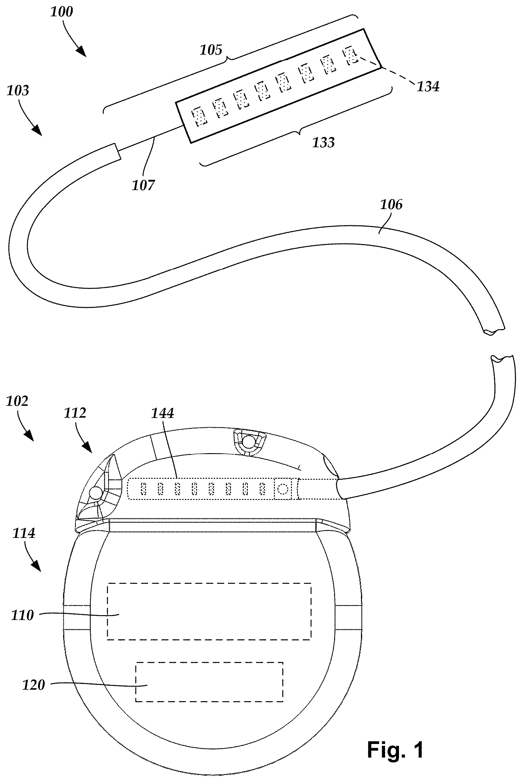
FIG. 1 illustrates schematically one embodiment of an electrical stimulation system 100. The electrical stimulation system includes a control module (e.g., a stimulator or pulse generator) 102 and a lead 103 coupleable to the control module 102. The lead 103 includes a distal end portion 105, shown schematically, but will be described in detail below (e.g., in FIGS. 3-5). In one embodiment, the distal end portion 105 extends from a lead body 106 and includes a transition element 107 and a distal electrode array or electrodes 133, such as electrode 134, and an array of terminals (e.g., 210 in FIG. 2A-2B) disposed along the one or more lead bodies 106. In at least some embodiments, the lead is isodiametric along a longitudinal length of the lead body 106.
The lead 103 can be coupled to the control module 102 in any suitable manner. In at least some embodiments, the lead 103 couples directly to the control module 102. In at least some other embodiments, the lead 103 couples to the control module 102 via one or more intermediate devices (200 in FIGS. 2A-2B). For example, in at least some embodiments one or more lead extensions 224 (see e.g., FIG. 2B) can be disposed between the lead 103 and the control module 102 to extend the distance between the lead 103 and the control module 102. Other intermediate devices may be used in addition to, or in lieu of, one or more lead extensions including, for example, a splitter, an adaptor, or the like or combinations thereof. It will be understood that, in the case where the electrical stimulation system 100 includes multiple elongated devices disposed between the lead 103 and the control module 102, the intermediate devices may be configured into any suitable arrangement.
The control module 102 typically includes a connector housing 112 and a sealed electronics housing 114. Stimulation circuitry 110 and an optional power source 120 are disposed in the electronics housing 114. A control module connector 144 is disposed in the connector housing 112. The control module connector 144 is configured and arranged to make an electrical connection between the lead 103 and the stimulation circuitry 110 of the control module 102.
The electrical stimulation system or components of the electrical stimulation system, including the lead body 106 and the control module 102, are typically implanted into the body of a patient. The electrical stimulation system can be used for a variety of applications including, but not limited to, brain stimulation, neural stimulation, spinal cord stimulation, muscle stimulation, and the like.
The electrodes 134 can be formed using any conductive, biocompatible material. Examples of suitable materials include metals, alloys, conductive polymers, conductive carbon, and the like, as well as combinations thereof. In at least some embodiments, one or more of the electrodes 134 are formed from one or more of: platinum, platinum iridium, palladium, palladium rhodium, or titanium. The number of electrodes 134 in each array 133 may vary. For example, there can be two, four, six, eight, ten, twelve, fourteen, sixteen, or more electrodes 134. As will be recognized, other numbers of electrodes 134 may also be used.
The electrodes of the lead body 106 are typically disposed in, or separated by, a non-conductive, biocompatible material such as, for example, silicone, polyurethane, polyetheretherketone ("PEEK"), epoxy, and the like or combinations thereof. The lead body 106 may be formed in the desired shape by any process including, for example, molding (including injection molding), casting, and the like. The non-conductive material typically extends from the distal end of the lead body 106 to the proximal end of the lead body 106.
Terminals (e.g., 210 in FIGS. 2A-2B) are typically disposed along the proximal end of the lead body 106 of the electrical stimulation system 100 (as well as any splitters, lead extensions, adaptors, or the like) for electrical connection to corresponding connector contacts (e.g., 214 and 240 in FIG. 2B). The connector contacts are disposed in connectors (e.g., 144 in FIGS. 1-2B; and 222 in FIG. 2B) which, in turn, are disposed on, for example, the control module 102 (or a lead extension, a splitter, an adaptor, or the like). Electrically conductive wires, cables, or the like (not shown) extend from the terminals to the electrodes 134. Typically, one or more electrodes 134 are electrically coupled to each terminal. In at least some embodiments, each terminal is only connected to one electrode 134.
The electrically conductive wires ("conductors") may be embedded in the non-conductive material of the lead body 106 or can be disposed in one or more lumens (not shown) extending along the lead body 106. In some embodiments, there is an individual lumen for each conductor. In other embodiments, two or more conductors extend through a lumen. There may also be one or more lumens (not shown) that open at, or near, the proximal end of the lead body 106, for example, for inserting a stylet to facilitate placement of the lead body 106 within a body of a patient. Additionally, there may be one or more lumens (not shown) that open at, or near, the distal end of the lead body 106, for example, for infusion of drugs or medication into the site of implantation of the lead body 106. In at least one embodiment, the one or more lumens are flushed continually, or on a regular basis, with saline, epidural fluid, or the like. In at least some embodiments, the one or more lumens are permanently or removably sealable at the distal end.
FIG. 2A is a schematic side view of one embodiment of a proximal end of one or more elongated devices 200 configured and arranged for coupling to one embodiment of the control module connector 144. The one or more elongated devices may include, for example, the lead body 106, one or more intermediate devices (e.g., the lead extension 224 of FIG. 2B, an adaptor, or the like or combinations thereof), or a combination thereof.
The control module connector 144 defines at least one port into which a proximal end of the elongated device 200 can be inserted, as shown by directional arrow 212. In FIG. 2A (and in other figures), the connector housing 112 is shown having one port 204. The connector housing 112 can define any suitable number of ports including, for example, one, two, three, four, five, six, seven, eight, or more ports.
The control module connector 144 also includes a plurality of connector contacts, such as connector contact 214, disposed within each port 204. When the elongated device 200 is inserted into the port 204, the connector contacts 214 can be aligned with a plurality of terminals 210 disposed along the proximal end(s) of the elongated device(s) 200 to electrically couple the control module 102 to the electrodes (134 of FIG. 1) disposed at a distal end of the lead 103. Examples of connectors in control modules are found in, for example, U.S. Pat. Nos. 7,244,150 and 8,224,450, which are incorporated by reference.
FIG. 2B is a schematic side view of another embodiment of the electrical stimulation system 100. The electrical stimulation system 100 includes a lead extension 224 that is configured and arranged to couple one or more elongated devices 200 (e.g., the lead body 106, an adaptor, another lead extension, or the like or combinations thereof) to the control module 102. In FIG. 2B, the lead extension 224 is shown coupled to a single port 204 defined in the control module connector 144. Additionally, the lead extension 224 is shown configured and arranged to couple to a single elongated device 200. In alternate embodiments, the lead extension 224 is configured and arranged to couple to multiple ports 204 defined in the control module connector 144, or to receive multiple elongated devices 200, or both.
A lead extension connector 222 is disposed on the lead extension 224. In FIG. 2B, the lead extension connector 222 is shown disposed at a distal end 226 of the lead extension 224. The lead extension connector 222 includes a connector housing 228. The connector housing 228 defines at least one port 230 into which terminals 210 of the elongated device 200 can be inserted, as shown by directional arrow 238. The connector housing 228 also includes a plurality of connector contacts, such as connector contact 240. When the elongated device 200 is inserted into the port 230, the connector contacts 240 disposed in the connector housing 228 can be aligned with the terminals 210 of the elongated device 200 to electrically couple the lead extension 224 to the electrodes (134 of FIG. 1) disposed along the lead (103 in FIG. 1).
In at least some embodiments, the proximal end of the lead extension 224 is similarly configured and arranged as a proximal end of the lead 103 (or other elongated device 200). The lead extension 224 may include a plurality of electrically conductive wires (not shown) that electrically couple the connector contacts 240 to a proximal end 248 of the lead extension 224 that is opposite to the distal end 226. In at least some embodiments, the conductive wires disposed in the lead extension 224 can be electrically coupled to a plurality of terminals (not shown) disposed along the proximal end 248 of the lead extension 224. In at least some embodiments, the proximal end 248 of the lead extension 224 is configured and arranged for insertion into a connector disposed in another lead extension (or another intermediate device). In other embodiments (and as shown in FIG. 2B), the proximal end 248 of the lead extension 224 is configured and arranged for insertion into the control module connector 144.
In at least some instances, a large control module, such as the control module 102 illustrated in FIGS. 1-2B, is not desirable. A smaller, more compact control module may be suitable for situations such as, for example, short-term implantation (for example, 1 or 2 weeks, 1, 2, 3, 4, 6, 8, 12, or 18 months), short-term trial (for example, 1 or 2 weeks, 1, 2, 3, 4, 6, 8, 12, or 18 months), clinical studies (for example, for a period of 1 or 2 weeks, 1, 2, 3, 4, 6, 8, 12, or 18 months), or the like. Such a control module may also be useful when a less invasive surgical implantation is desired, recommended, or required. In some instances, a patient or clinician may be willing to charge the control module more frequently if the control module is smaller or the surgery is less invasive. In addition, there may be more options in the body of the patient for implantation of a smaller control module than are available for the larger control module (which is often implanted in the thoracic body cavity or the buttocks due to the size of the device.) A smaller control module may also be less expensive and particularly useful for trials to determine whether electrical stimulation is beneficial. In at least some embodiments, the electrical stimulation system with the smaller control module can be upgraded to an electrical stimulation system such as that illustrated in FIGS. 1-2B if the trial shows sufficient benefit to the patient. In at least some embodiments, the smaller control module may allow for the device to be Mill (magnetic resonance imaging) conditionally safe because of its implant location and size.
In some embodiments, the control module can be made smaller by permanently affixing the lead (or a lead extension) to the control module. For example, the lead can be hardwired to the stimulation circuitry so that the control module does not need a connector and header.
FIG. 3 illustrates, schematically, a distal end portion 305 implanted on a target nerve 350 according to an embodiment of the present invention. The distal end portion 305 includes an electrical stimulation device 352 (hereinafter referred to as a sleeve 352), a lead body 306 and a transition element 307 electrically connecting the sleeve 352 with the lead body 306. In one embodiment, the transition element 307 may take the form of a flexible, ribbon cable to provide strain relief vis-a-vis the lead body 306 and the sleeve 352. The ribbon cables may also be referred to as multi-wire planar cable, which is understood to be a cable with many conducting wires running parallel to each other on the same flat plane, such as ribbon cables used to connect peripherals and other components in the computing industry. The transition element 307 may have a bellowed configuration to allow for the flexibility. The lead body 306 is structurally the same or similar to the lead body 106 (FIG. 1), operates in a same or similar manner, and may be manufactured in accordance with one or more of the methods disclosed herein and disclosed in U.S. Patent Application No. 2007/0150036, which is hereby incorporated by reference in its entirety, or in accordance with other methods or references cited herein.
The lead body 306 and the sleeve 352 can be made from a non-conductive, biocompatible material such as, for example, silicone, polyurethane, polyetheretherketone ("PEEK"), epoxy, and the like or combinations thereof. The lead body 306 and sleeve 352 may be formed in the desired shape by any process including, for example, molding (including injection molding), casting, and the like.
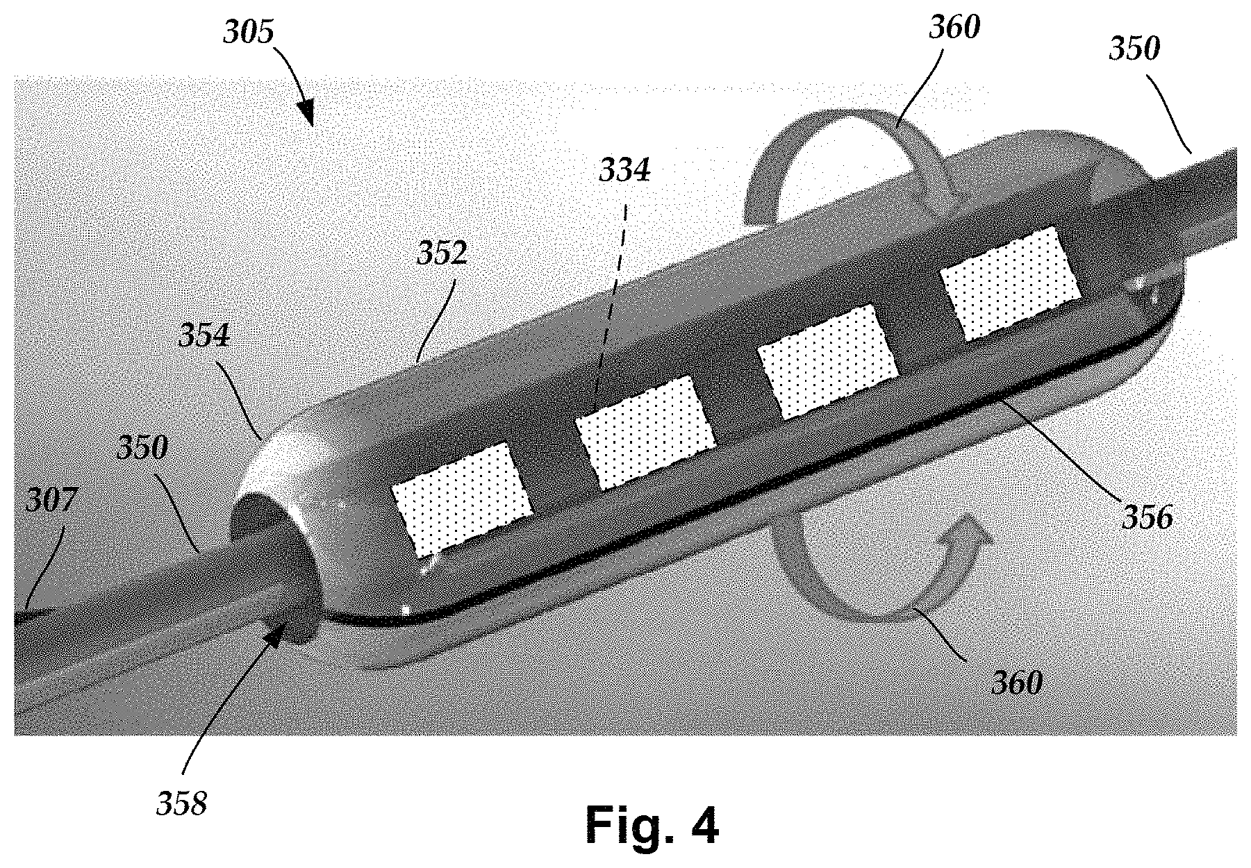
Referring to FIG. 4, the sleeve 352 may permit stimulation of the target nerve 350, for example a vagus or sympathetic nerve, by using a plurality of electrodes 334 disposed into the sleeve 352. By way of example, the sleeve 352 can operate to provide vagus or sympathetic nerve stimulation. When using traditional leads to stimulate the target nerve, it may be difficult to initiate and maintain contact between the traditional lead and the target nerve. In at least some embodiments, the sleeve 352 may advantageously permit an easier implantation around the target nerve than conventional leads that wrap helically around the target nerve. In at least some embodiments, the sleeve 352 may also permit selective stimulation of different regions of the target nerve 350. The number of electrodes 334 as well as the arrangement of the electrodes 334 can vary depending on the type of nerve being stimulated, a region of the nerve being stimulated, or any combination thereof.
In one embodiment, the sleeve 352 is made from silicone, more specifically liquid silicone rubber (LSR), with the electrodes 334 disposed thereon. The sleeve 352 may be manufactured by placing the electrodes 334 onto an LSR pad or carrier and then attaching electrically conductive cables or wires ("conductors")(not shown) to the electrodes 334. Hence, FIG. 4 shows the electrodes 334 in dashed line format.
The electrodes 334 can be formed using any conductive, biocompatible material. Examples of suitable materials include metals, alloys, conductive polymers, conductive carbon, and the like, as well as combinations thereof. In at least some embodiments, one or more of the electrodes 334 are formed from one or more of: platinum, platinum iridium, palladium, palladium rhodium, or titanium. The electrodes 334 may take the form of segmented electrodes, have a variety of shapes such as, but not limited to, a concave, convex or otherwise curved shape, a box shape, a dish or parabolic shape, or any combination thereof. In at least some embodiments, the electrodes 334 may take the form of segmented electrodes having a shape complementary to a body or carrier onto which they are disposed.
Any suitable number of electrodes 334 can be disposed on the sleeve 352 including, for example, four, five, six, seven, eight, nine, ten, eleven, twelve, fourteen, sixteen, twenty-four, thirty-two, or more electrodes 334. The electrodes 334 can be disposed on the sleeve 352 in any suitable arrangement. In at least some embodiments, an inward facing surface of the electrode 334 is flush with an inner surface of the sleeve 352. In yet other embodiments, the inward facing surface of the electrode 334 is recessed relative to the inner surface of the sleeve 352.
The electrodes 334 may be arranged into columns, rows or some combination thereof. In at least some embodiments, one column or row includes two, three, four, five, six, eight or more electrodes 334. The arrangement of the electrode(s) 334 may vary. For example, the electrodes 334 may be arranged in two, three, four or more parallel columns or rows where such columns or rows can be aligned or staggered from one another, or in any other desired column or row arrangement. The electrodes may also be arranged, for example, in a row, or "in line," along the longitudinal axis of a small diameter lead body. Optionally, the electrodes may be placed linearly, circularly, or elliptically. The arrangement of electrodes may be symmetrical or asymmetrical. As will be recognized, other arrangements of electrodes are also possible.
In at least some embodiments, the sleeve 352 is formed into an elongated, cylindrical shape having tapered end portions 354 and a slit 356, wherein the slit 356 may be introduced during the molding process or may be cut, such as, but not limited to, a laser cut, after the molding process. The slit 356 extends for an entire length of the sleeve 352 and extends radially inward through a portion of the sleeve into a nerve channel 358, which is defined by an inner surface of the sleeve 352. In other embodiments, the sleeve 352 can have any shape or cross-section that enables opening and closing of the sleeve 352 during manipulation of the sleeve relative to the target nerve 350. Examples of the suitable cross-sections include, but are not limited to, elliptical, circular, oval, and so forth. Further, the sleeve 352 may have an unsymmetrical shape and structure that permits opening and closing of the sleeve 352. The tapered end portions 354 may advantageously provide more of a gentle transition at each end of the sleeve 352 since the tapered end portions 354 help to make the sleeve less rigid or stiff near each end. In at least some embodiments, the reduced rigidity or stiffness from the tapered end portions 354 may provide strain relief vis-a-vis the target nerve 350. The tapered end portions 354 may take a variety of shapes such as, but not limited to, rounded, sloped, stepped, or otherwise transitioned from the thickness of the sleeve 352 to a free edge of the end portions 354.
In at least some embodiments and during installation around the target nerve 350, the sleeve 352 is opened in a clam shell manner with rotation occurring about a common hinge line opposite the slit 356. In at least some embodiments, the material of the sleeve 352 functions as a common, elastic hinge line allowing the sleeve 352 to rotate from a closed position to an open position, and vice-versa, in the clam shell manner, preferably without permanent deformation (i.e., "elastic") to the sleeve 352. The sleeve 352 is opened by an amount sufficient to allow it to be fed, slid, moved or otherwise transitioned over and onto or removed from the target nerve 350. Once in position over the target nerve 350, the sleeve 352 is closed in a clamshell manner as indicated by rotational arrows 360. The closed position may take the form of sleeve edges adjacent to the slit 356 being urged into physical contact or remaining slightly spaced apart. In the latter situation, a spatial distance between the sleeve edges adjacent to the slit 356 is smaller than a diameter of the target nerve 350, thus retaining the target nerve 350 within the nerve channel 358 of the sleeve 352. The nerve channel 352 is preferably sized to prevent or reduce compression of target nerve 350 by the sleeve 352 when in the closed position.
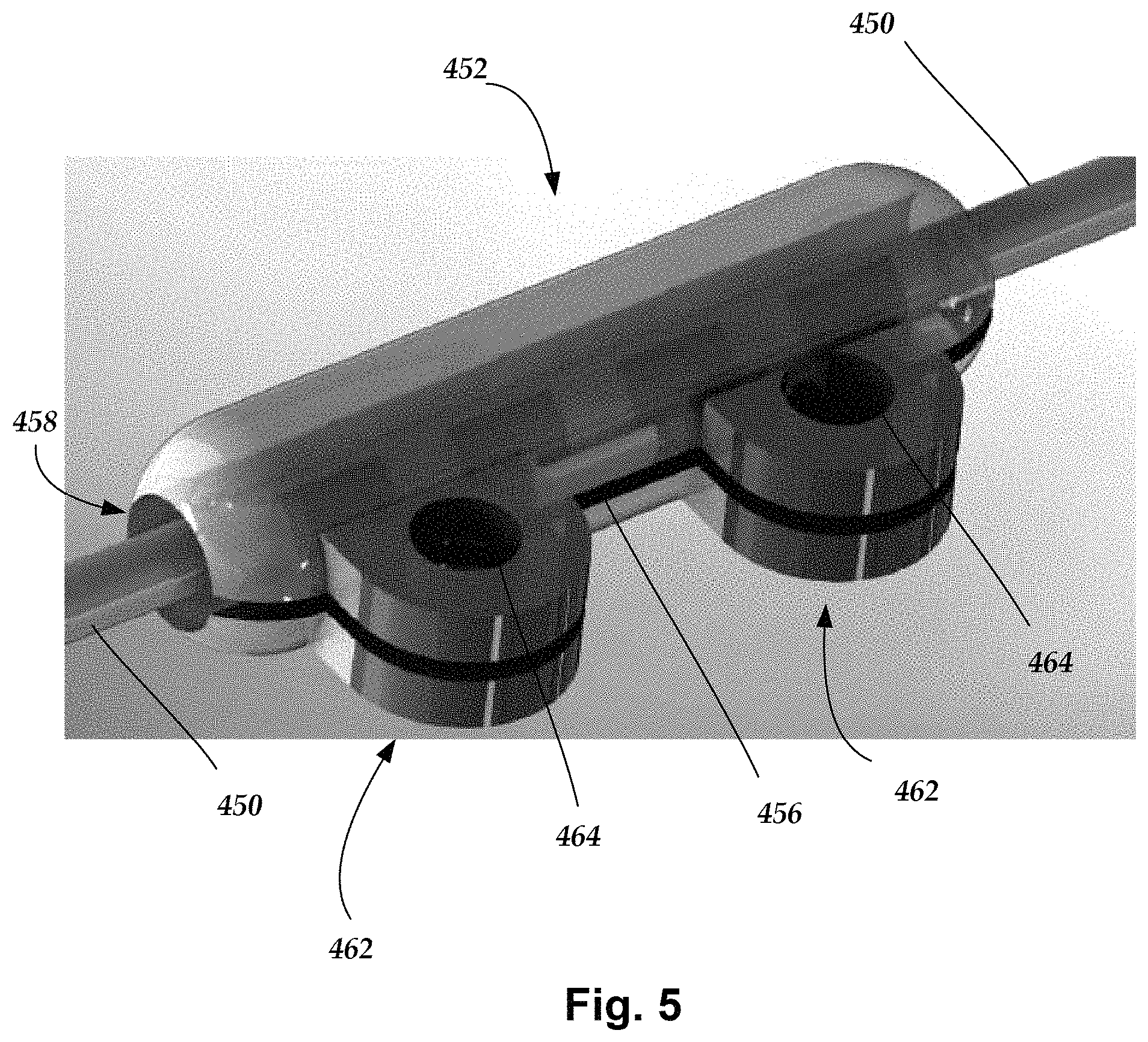
FIG. 5 shows, schematically, a sleeve 452 implanted and closed upon on a target nerve 450 according to at least some embodiments. In at least some embodiments, the sleeve 452 includes suture eyelets or tabs 462 having suture holes 464 that can be pre-made or pre-formed during molding of the sleeve 452. The suture tabs 462 extend from the sleeve 452 and may approximate the shape of a pillow block, but a variety of other shapes are also contemplated. The illustrated embodiment shows two suture tabs 462, but the sleeve 452 may have a single suture tab 462 or more than two suture tabs 462. A slit 456 extends through the suture tabs 462 and through one side of the sleeve 452 and into a nerve channel 458 defined by the sleeve 452. The extended suture tabs 462 permit the sleeve 452 to be anchored (e.g., sutured) to the patient's tissue without the need to wrap a suture around the sleeve 452. The suture tabs 462 may advantageously permit closing and anchoring of the sleeve 452 without undesirably compressing the sleeve 452 around the target nerve.
During implantation, the sleeve 452 is opened and slid over the target nerve 450 (similar to the previous embodiment of FIG. 3), closed, and then sutured to a patient's tissue. The suture tabs 462 may be located on areas of the sleeve 452 that would not necessitate making a slit through the suture tabs 462. In at least some embodiments, the suture tabs 462 may be made out of the same material of the sleeve 452, a different material (e.g., stiffer or stronger material), embedded with stiffening elements (not shown), or any combination thereof. Further, the suture tabs 462 may attached to the sleeve 452 after the molding process or may be formed integrally with the sleeve 452 during the molding process.
FIG. 6 is a schematic overview of one embodiment of components of an electrical stimulation arrangement 504 that includes an electrical stimulation system 500 with a lead 502, stimulation circuitry 506, a power source 508, and an antenna 510. The electrical stimulation system can be, for example, any of the electrical stimulation systems described above. It will be understood that the electrical stimulation arrangement can include more, fewer, or different components and can have a variety of different configurations including those configurations disclosed in the stimulator references cited herein.
If the power source 508 is a rechargeable battery or chargeable capacitor, the power source may be recharged/charged using the antenna 510, if desired. Power can be provided for recharging/charging by inductively coupling the power source 508 through the antenna 510 to a recharging unit 536 external to the user. Examples of such arrangements can be found in the references identified above.
In one embodiment, electrical current is emitted by the electrodes (such as electrodes 134 in FIG. 1) on the lead 502 to stimulate nerve fibers, muscle fibers, or other body tissues near the electrical stimulation system. The stimulation circuitry 506 can include, among other components, a processor 534 and a receiver 532. The processor 534 is generally included to control the timing and electrical characteristics of the electrical stimulation system. For example, the processor 534 can, if desired, control one or more of the timing, frequency, strength, duration, and waveform of the pulses. In addition, the processor 534 can select which electrodes can be used to provide stimulation, if desired. In some embodiments, the processor 534 selects which electrode(s) are cathodes and which electrode(s) are anodes. In some embodiments, the processor 534 is used to identify which electrodes provide the most useful stimulation of the desired tissue.
Any processor can be used and can be as simple as an electronic device that, for example, produces pulses at a regular interval or the processor can be capable of receiving and interpreting instructions from an external programming unit 538 that, for example, allows modification of pulse characteristics. In the illustrated embodiment, the processor 534 is coupled to a receiver 532 which, in turn, is coupled to the antenna 510. This allows the processor 534 to receive instructions from an external source to, for example, direct the pulse characteristics and the selection of electrodes, if desired.
In one embodiment, the antenna 510 is capable of receiving signals (e.g., RF signals) from an external telemetry unit 540 that is programmed by the programming unit 538. The programming unit 538 can be external to, or part of, the telemetry unit 540. The telemetry unit 540 can be a device that is worn on the skin of the user or can be carried by the user and can have a form similar to a pager, cellular phone, or remote control, if desired. As another alternative, the telemetry unit 540 may not be worn or carried by the user but may only be available at a home station or at a clinician's office. The programming unit 538 can be any unit that can provide information to the telemetry unit 540 for transmission to the electrical stimulation system 500. The programming unit 538 can be part of the telemetry unit 540 or can provide signals or information to the telemetry unit 540 via a wireless or wired connection. One example of a suitable programming unit is a computer operated by the user or clinician to send signals to the telemetry unit 540.
The signals sent to the processor 534 via the antenna 510 and the receiver 532 can be used to modify or otherwise direct the operation of the electrical stimulation system 500. For example, the signals may be used to modify the pulses of the electrical stimulation system such as modifying one or more of pulse duration, pulse frequency, pulse waveform, and pulse strength. The signals may also direct the electrical stimulation system 500 to cease operation, to start operation, to start charging the battery, or to stop charging the battery.
Optionally, the electrical stimulation system 500 may include a transmitter (not shown) coupled to the processor 534 and the antenna 510 for transmitting signals back to the telemetry unit 540 or another unit capable of receiving the signals. For example, the electrical stimulation system 500 may transmit signals indicating whether the electrical stimulation system 500 is operating properly or not or indicating when the battery needs to be charged or the level of charge remaining in the battery. The processor 534 may also be capable of transmitting information about the pulse characteristics so that a user or clinician can determine or verify the characteristics.
The above specification provides a description of the structure, manufacture, and use of the invention. Since many embodiments of the invention can be made without departing from the spirit and scope of the invention, the invention also resides in the claims hereinafter appended.
* * * * *
D00000
D00001
D00002
D00003
D00004
D00005
D00006
D00007
XML
uspto.report is an independent third-party trademark research tool that is not affiliated, endorsed, or sponsored by the United States Patent and Trademark Office (USPTO) or any other governmental organization. The information provided by uspto.report is based on publicly available data at the time of writing and is intended for informational purposes only.
While we strive to provide accurate and up-to-date information, we do not guarantee the accuracy, completeness, reliability, or suitability of the information displayed on this site. The use of this site is at your own risk. Any reliance you place on such information is therefore strictly at your own risk.
All official trademark data, including owner information, should be verified by visiting the official USPTO website at www.uspto.gov. This site is not intended to replace professional legal advice and should not be used as a substitute for consulting with a legal professional who is knowledgeable about trademark law.