Self-contained, self-piercing, side-expelling marking apparatus
Field , et al. October 27, 2
U.S. patent number 10,813,716 [Application Number 15/853,052] was granted by the patent office on 2020-10-27 for self-contained, self-piercing, side-expelling marking apparatus. This patent grant is currently assigned to Bard Peripheral Vascular, Inc., Bard Shannon Limited. The grantee listed for this patent is Bard Peripheral Vascular, Inc., BARD SHANNON LIMITED. Invention is credited to Richard M. Chesbrough, Steven E. Field, Ryan L. Goosen, Brian R. Mulder.


| United States Patent | 10,813,716 |
| Field , et al. | October 27, 2020 |
Self-contained, self-piercing, side-expelling marking apparatus
Abstract
A method of operating a tissue marking apparatus includes providing a tissue marking apparatus having a cannula, a stylet, and an imaging marker, the cannula having a peripheral wall forming a lumen and a lateral opening in the peripheral wall that is open to the lumen, and having a resilient end wall extending downwardly from the peripheral wall at a distal extent of the lateral opening, the stylet being slidably received within the lumen of the cannula for movement in the lumen; moving the stylet in a distal direction to expel the imaging marker from the lateral opening; and continue moving the stylet in the distal direction to deflect the resilient end wall of the cannula such that a distal end of the stylet passes beneath the resilient end wall to substantially close off the lateral opening of the cannula.
| Inventors: | Field; Steven E. (Grand Rapids, MI), Goosen; Ryan L. (Caledonia, MI), Mulder; Brian R. (Rockford, MI), Chesbrough; Richard M. (Bloomfield Hills, MI) | ||||||||||
|---|---|---|---|---|---|---|---|---|---|---|---|
| Applicant: |
|
||||||||||
| Assignee: | Bard Peripheral Vascular, Inc.
(Franklin Lakes, NJ) Bard Shannon Limited (Nieuwegein, NL) |
||||||||||
| Family ID: | 1000005139648 | ||||||||||
| Appl. No.: | 15/853,052 | ||||||||||
| Filed: | December 22, 2017 |
Prior Publication Data
| Document Identifier | Publication Date | |
|---|---|---|
| US 20180200019 A1 | Jul 19, 2018 | |
Related U.S. Patent Documents
| Application Number | Filing Date | Patent Number | Issue Date | ||
|---|---|---|---|---|---|
| 15381717 | Dec 16, 2016 | 9848956 | |||
| 15078847 | Mar 23, 2016 | ||||
| 12850844 | Aug 5, 2010 | ||||
| 11275918 | Oct 26, 2010 | 7819820 | |||
| 10710587 | Jul 22, 2004 | ||||
| 10707044 | Sep 9, 2008 | 7424320 | |||
| 60427048 | Nov 18, 2002 | ||||
| Current U.S. Class: | 1/1 |
| Current CPC Class: | A61B 90/39 (20160201); A61B 5/064 (20130101); A61B 2090/3987 (20160201); A61B 2090/3908 (20160201) |
| Current International Class: | A61B 5/00 (20060101); A61B 90/00 (20160101); A61B 5/06 (20060101) |
References Cited [Referenced By]
U.S. Patent Documents
| 2899362 | August 1959 | Sieger, Jr. et al. |
| 2907327 | October 1959 | White |
| 3005457 | October 1961 | Millman |
| 3128744 | April 1964 | Jefferts et al. |
| 3402712 | September 1968 | Eisenhand |
| 3516412 | June 1970 | Ackerman |
| 3818894 | June 1974 | Wichterle et al. |
| 3820545 | June 1974 | Jefferts |
| 3823212 | July 1974 | Chvapil |
| 3921632 | November 1975 | Bardani |
| 4005699 | February 1977 | Bucalo |
| 4007732 | February 1977 | Kvavle et al. |
| 4041931 | August 1977 | Elliott et al. |
| 4086914 | May 1978 | Moore |
| 4103690 | August 1978 | Harris |
| 4105030 | August 1978 | Kercso |
| 4127774 | November 1978 | Gillen |
| 4172449 | October 1979 | LeRoy et al. |
| 4197846 | April 1980 | Bucalo |
| 4217889 | August 1980 | Radovan et al. |
| 4228799 | October 1980 | Anichkov et al. |
| 4276885 | July 1981 | Tickner et al. |
| 4294241 | October 1981 | Miyata |
| 4298998 | November 1981 | Naficy |
| 4331654 | May 1982 | Morris |
| 4347234 | August 1982 | Wahlig et al. |
| 4390018 | June 1983 | Zukowski |
| 4400170 | August 1983 | McNaughton et al. |
| 4401124 | August 1983 | Guess et al. |
| 4405314 | September 1983 | Cope |
| 4428082 | January 1984 | Naficy |
| 4438253 | March 1984 | Casey et al. |
| 4442843 | April 1984 | Rasor et al. |
| 4470160 | September 1984 | Cavon |
| 4487209 | December 1984 | Mehl |
| 4545367 | October 1985 | Tucci |
| 4582061 | April 1986 | Fry |
| 4582640 | April 1986 | Smestad et al. |
| 4588395 | May 1986 | Lemelson |
| 4597753 | July 1986 | Turley |
| 4647480 | March 1987 | Ahmed |
| 4655226 | April 1987 | Lee |
| 4661103 | April 1987 | Harman |
| 4682606 | July 1987 | DeCaprio |
| 4693237 | September 1987 | Hoffman et al. |
| 4718433 | January 1988 | Feinstein |
| 4740208 | April 1988 | Cavon |
| 4762128 | August 1988 | Rosenbluth |
| 4813062 | March 1989 | Gilpatrick |
| 4820267 | April 1989 | Harman |
| 4832680 | May 1989 | Haber et al. |
| 4832686 | May 1989 | Anderson |
| 4847049 | July 1989 | Yamamoto |
| 4863470 | September 1989 | Carter |
| 4870966 | October 1989 | Dellon et al. |
| 4874376 | October 1989 | Hawkins, Jr. |
| 4889707 | December 1989 | Day et al. |
| 4909250 | March 1990 | Smith |
| 4931059 | June 1990 | Markham |
| 4938763 | July 1990 | Dunn et al. |
| 4950234 | August 1990 | Fujioka et al. |
| 4950665 | August 1990 | Floyd |
| 4963150 | October 1990 | Brauman |
| 4970298 | November 1990 | Silver et al. |
| 4989608 | February 1991 | Ratner |
| 4994013 | February 1991 | Suthanthiran et al. |
| 4994028 | February 1991 | Leonard et al. |
| 5012818 | May 1991 | Joishy |
| 5013090 | May 1991 | Matsuura |
| 5018530 | May 1991 | Rank et al. |
| 5035891 | July 1991 | Runkel et al. |
| 5059197 | October 1991 | Urie et al. |
| 5081997 | January 1992 | Bosley, Jr. et al. |
| 5120802 | June 1992 | Mares et al. |
| 5125413 | June 1992 | Baran |
| 5137928 | August 1992 | Erbel et al. |
| 5141748 | August 1992 | Rizzo |
| 5147295 | September 1992 | Stewart |
| 5147307 | September 1992 | Gluck |
| 5147631 | September 1992 | Glajch et al. |
| 5162430 | November 1992 | Rhee et al. |
| 5163896 | November 1992 | Suthanthiran et al. |
| 5195540 | March 1993 | Shiber |
| 5197482 | March 1993 | Rank et al. |
| 5199441 | April 1993 | Hogle |
| 5201704 | April 1993 | Ray |
| 5219339 | June 1993 | Saito |
| 5221269 | June 1993 | Miller et al. |
| 5234426 | August 1993 | Rank et al. |
| 5236410 | August 1993 | Granov et al. |
| 5242759 | September 1993 | Hall |
| 5250026 | October 1993 | Ehrlich et al. |
| 5271961 | December 1993 | Mathiowitz et al. |
| 5273532 | December 1993 | Niezink et al. |
| 5280788 | January 1994 | Janes et al. |
| 5281197 | January 1994 | Arias et al. |
| 5281408 | January 1994 | Unger |
| 5282781 | February 1994 | Liprie |
| 5284479 | February 1994 | de Jong |
| 5289831 | March 1994 | Bosley |
| 5290310 | March 1994 | Makower et al. |
| 5312435 | May 1994 | Nash et al. |
| 5320100 | June 1994 | Herweck et al. |
| 5320613 | June 1994 | Houge et al. |
| 5328955 | July 1994 | Rhee et al. |
| 5334216 | August 1994 | Vidal et al. |
| 5334381 | August 1994 | Unger |
| 5344640 | September 1994 | Deutsch et al. |
| 5353804 | October 1994 | Komberg et al. |
| 5354623 | October 1994 | Hall |
| 5358514 | October 1994 | Schulman et al. |
| 5360416 | November 1994 | Ausherman et al. |
| 5366756 | November 1994 | Chesterfield et al. |
| 5368030 | November 1994 | Zinreich et al. |
| 5388588 | February 1995 | Nabai et al. |
| 5394875 | March 1995 | Lewis et al. |
| 5395319 | March 1995 | Hirsch et al. |
| 5405402 | April 1995 | Dye et al. |
| 5409004 | April 1995 | Sloan |
| 5417708 | May 1995 | Hall et al. |
| 5422730 | June 1995 | Barlow et al. |
| 5425366 | June 1995 | Reinhardt et al. |
| 5431639 | July 1995 | Shaw |
| 5433204 | July 1995 | Olson |
| 5449560 | September 1995 | Antheunis et al. |
| 5451406 | September 1995 | Lawin et al. |
| 5458643 | October 1995 | Oka et al. |
| 5460182 | October 1995 | Goodman et al. |
| 5469847 | November 1995 | Zinreich et al. |
| 5475052 | December 1995 | Rhee et al. |
| 5490521 | February 1996 | Davis et al. |
| 5494030 | February 1996 | Swartz et al. |
| 5499989 | March 1996 | LaBash |
| 5507807 | April 1996 | Shippert |
| 5508021 | April 1996 | Grinstaff et al. |
| 5514085 | May 1996 | Yoon |
| 5522896 | June 1996 | Prescott |
| 5538726 | July 1996 | Order |
| 5542915 | August 1996 | Edwards et al. |
| 5545180 | August 1996 | Le et al. |
| 5549560 | August 1996 | Van de Wijdeven |
| 5567413 | October 1996 | Klaveness et al. |
| RE35391 | December 1996 | Brauman |
| 5580568 | December 1996 | Greff et al. |
| 5585112 | December 1996 | Unger et al. |
| 5611352 | March 1997 | Kobren et al. |
| 5626611 | May 1997 | Liu et al. |
| 5628781 | May 1997 | Williams et al. |
| 5629008 | May 1997 | Lee |
| 5636255 | June 1997 | Ellis |
| 5643246 | July 1997 | Leeb et al. |
| 5646146 | July 1997 | Faarup et al. |
| 5651772 | July 1997 | Arnett |
| 5657366 | August 1997 | Nakayama |
| 5665092 | September 1997 | Mangiardi et al. |
| 5667767 | September 1997 | Greff et al. |
| 5669882 | September 1997 | Pyles |
| 5673841 | October 1997 | Schulze et al. |
| 5676146 | October 1997 | Scarborough |
| 5676925 | October 1997 | Klaveness et al. |
| 5688490 | November 1997 | Tournier et al. |
| 5690120 | November 1997 | Jacobsen et al. |
| 5695480 | December 1997 | Evans et al. |
| 5702128 | December 1997 | Maxim et al. |
| 5702682 | December 1997 | Thompson |
| 5702716 | December 1997 | Dunn et al. |
| 5716981 | February 1998 | Hunter et al. |
| 5747060 | May 1998 | Sackler et al. |
| 5749887 | May 1998 | Heske et al. |
| 5752974 | May 1998 | Rhee et al. |
| 5762903 | June 1998 | Park et al. |
| 5769086 | June 1998 | Ritchart et al. |
| 5776496 | July 1998 | Violante et al. |
| 5779647 | July 1998 | Chau et al. |
| 5782764 | July 1998 | Werne |
| 5782771 | July 1998 | Hussman |
| 5782775 | July 1998 | Milliman et al. |
| 5795308 | August 1998 | Russin |
| 5799099 | August 1998 | Wang et al. |
| 5800362 | September 1998 | Kobren et al. |
| 5800389 | September 1998 | Burney et al. |
| 5800445 | September 1998 | Ratcliff et al. |
| 5800541 | September 1998 | Rhee et al. |
| 5810884 | September 1998 | Kim |
| 5817022 | October 1998 | Vesely |
| 5820918 | October 1998 | Ronan et al. |
| 5821184 | October 1998 | Haines et al. |
| 5823198 | October 1998 | Jones et al. |
| 5824042 | October 1998 | Lombardi et al. |
| 5824081 | October 1998 | Knapp et al. |
| 5826776 | October 1998 | Schulze et al. |
| 5830178 | November 1998 | Jones et al. |
| 5830222 | November 1998 | Makower |
| 5842477 | December 1998 | Naughton et al. |
| 5842999 | December 1998 | Pruitt et al. |
| 5845646 | December 1998 | Lemelson |
| 5846220 | December 1998 | Elsberry |
| 5851508 | December 1998 | Greff et al. |
| 5853366 | December 1998 | Dowlatshahi |
| 5865806 | February 1999 | Howell |
| 5869080 | February 1999 | McGregor et al. |
| 5871501 | February 1999 | Leschinsky et al. |
| 5876340 | March 1999 | Tu et al. |
| 5879357 | March 1999 | Heaton et al. |
| 5891558 | April 1999 | Bell et al. |
| 5897507 | April 1999 | Kortenbach et al. |
| 5902310 | May 1999 | Foerster et al. |
| 5911705 | June 1999 | Howell |
| 5916164 | June 1999 | Fitzpatrick et al. |
| 5921933 | July 1999 | Sarkis et al. |
| 5922024 | July 1999 | Janzen et al. |
| 5928626 | July 1999 | Klaveness et al. |
| 5928773 | July 1999 | Andersen |
| 5941439 | August 1999 | Kammerer et al. |
| 5941890 | August 1999 | Voegele et al. |
| 5942209 | August 1999 | Leavitt et al. |
| 5948425 | September 1999 | Janzen et al. |
| 5954670 | September 1999 | Baker |
| 5972817 | October 1999 | Haines et al. |
| 5976146 | November 1999 | Ogawa et al. |
| 5980564 | November 1999 | Stinson |
| 5989265 | November 1999 | Bouquet De La Joliniere et al. |
| 6015541 | January 2000 | Greff et al. |
| 6027471 | February 2000 | Fallon et al. |
| 6030333 | February 2000 | Sioshansi et al. |
| 6053925 | April 2000 | Barnhart |
| 6056700 | May 2000 | Burney et al. |
| 6066122 | May 2000 | Fisher |
| 6066325 | May 2000 | Wallace et al. |
| 6071301 | June 2000 | Cragg et al. |
| 6071310 | June 2000 | Picha et al. |
| 6071496 | June 2000 | Stein et al. |
| 6090996 | July 2000 | Li |
| 6096065 | August 2000 | Crowley |
| 6096070 | August 2000 | Ragheb et al. |
| 6106473 | August 2000 | Violante et al. |
| 6117108 | September 2000 | Woehr et al. |
| 6120536 | September 2000 | Ding et al. |
| 6135993 | October 2000 | Hussman |
| 6142955 | November 2000 | Farascioni et al. |
| 6159240 | December 2000 | Sparer et al. |
| 6159445 | December 2000 | Klaveness et al. |
| 6161034 | December 2000 | Burbank et al. |
| 6162192 | December 2000 | Cragg et al. |
| 6166079 | December 2000 | Follen et al. |
| 6173715 | January 2001 | Sinanan et al. |
| 6174330 | January 2001 | Stinson |
| 6177062 | January 2001 | Stein et al. |
| 6181960 | January 2001 | Jensen et al. |
| 6183497 | February 2001 | Sing et al. |
| 6190350 | February 2001 | Davis et al. |
| 6190353 | February 2001 | Makower et al. |
| 6200258 | March 2001 | Slater et al. |
| 6203507 | March 2001 | Wadsworth et al. |
| 6203524 | March 2001 | Burney et al. |
| 6203568 | March 2001 | Lombardi et al. |
| 6213957 | April 2001 | Milliman et al. |
| 6214045 | April 2001 | Corbitt, Jr. et al. |
| 6214315 | April 2001 | Greff et al. |
| 6220248 | April 2001 | Voegele et al. |
| 6224630 | May 2001 | Bao et al. |
| 6228049 | May 2001 | Schroeder et al. |
| 6228055 | May 2001 | Foerster et al. |
| 6231615 | May 2001 | Preissman |
| 6234177 | May 2001 | Barsch |
| 6241687 | June 2001 | Voegele et al. |
| 6241734 | June 2001 | Scribner et al. |
| 6251135 | June 2001 | Stinson et al. |
| 6251418 | June 2001 | Ahern et al. |
| 6261243 | July 2001 | Burney et al. |
| 6261302 | July 2001 | Voegele et al. |
| 6264917 | July 2001 | Klaveness et al. |
| 6270464 | August 2001 | Fulton, III et al. |
| 6270472 | August 2001 | Antaki et al. |
| 6287278 | September 2001 | Woehr et al. |
| 6287332 | September 2001 | Bolz et al. |
| 6289229 | September 2001 | Crowley |
| 6306154 | October 2001 | Hudson et al. |
| 6312429 | November 2001 | Burbank et al. |
| 6316522 | November 2001 | Loomis et al. |
| 6325789 | December 2001 | Janzen et al. |
| 6335029 | January 2002 | Kamath et al. |
| 6336904 | January 2002 | Nikolchev |
| 6340367 | January 2002 | Stinson et al. |
| 6343227 | January 2002 | Crowley |
| 6347240 | February 2002 | Foley et al. |
| 6347241 | February 2002 | Burbank et al. |
| 6350244 | February 2002 | Fisher |
| 6350274 | February 2002 | Li |
| 6354989 | March 2002 | Nudeshima |
| 6356112 | March 2002 | Tran et al. |
| 6356782 | March 2002 | Sirimanne et al. |
| 6358217 | March 2002 | Bourassa |
| 6363940 | April 2002 | Krag |
| 6371904 | April 2002 | Sirimanne et al. |
| 6394965 | May 2002 | Klein |
| 6403758 | June 2002 | Loomis |
| 6405733 | June 2002 | Fogarty et al. |
| 6409742 | June 2002 | Fulton, III et al. |
| 6419621 | July 2002 | Sioshansi et al. |
| 6424857 | July 2002 | Henrichs et al. |
| 6425903 | July 2002 | Voegele |
| 6427081 | July 2002 | Burbank et al. |
| 6436030 | August 2002 | Rehil |
| 6447524 | September 2002 | Knodel et al. |
| 6447527 | September 2002 | Thompson et al. |
| 6450937 | September 2002 | Mercereau et al. |
| 6450938 | September 2002 | Miller |
| 6471700 | October 2002 | Burbank et al. |
| 6478790 | November 2002 | Bardani |
| 6506156 | January 2003 | Jones et al. |
| 6511468 | January 2003 | Cragg et al. |
| 6511650 | January 2003 | Eiselt et al. |
| 6537193 | March 2003 | Lennox |
| 6540981 | April 2003 | Klaveness et al. |
| 6544185 | April 2003 | Montegrande |
| 6544231 | April 2003 | Palmer et al. |
| 6544269 | April 2003 | Osborne et al. |
| 6551253 | April 2003 | Worm et al. |
| 6554760 | April 2003 | Lamoureux et al. |
| 6562317 | May 2003 | Greff et al. |
| 6564806 | May 2003 | Fogarty et al. |
| 6565551 | May 2003 | Jones et al. |
| 6567689 | May 2003 | Burbank et al. |
| 6575888 | June 2003 | Zamora et al. |
| 6575991 | June 2003 | Chesbrough et al. |
| 6585773 | July 2003 | Xie |
| 6605047 | August 2003 | Zarins et al. |
| 6610026 | August 2003 | Cragg et al. |
| 6613002 | September 2003 | Clark et al. |
| 6616630 | September 2003 | Woehr et al. |
| 6626850 | September 2003 | Chau et al. |
| 6626899 | September 2003 | Houser et al. |
| 6628982 | September 2003 | Thomas et al. |
| 6629947 | October 2003 | Sahatjian et al. |
| 6636758 | October 2003 | Sanchez et al. |
| 6638234 | October 2003 | Burbank et al. |
| 6638308 | October 2003 | Corbitt, Jr. et al. |
| 6652442 | November 2003 | Gatto |
| 6656192 | December 2003 | Espositio et al. |
| 6659933 | December 2003 | Asano |
| 6662041 | December 2003 | Burbank et al. |
| 6699205 | March 2004 | Fulton, III et al. |
| 6712774 | March 2004 | Voegele et al. |
| 6712836 | March 2004 | Berg et al. |
| 6716444 | April 2004 | Castro et al. |
| 6725083 | April 2004 | Burbank et al. |
| 6730042 | May 2004 | Fulton et al. |
| 6730044 | May 2004 | Stephens et al. |
| 6746661 | June 2004 | Kaplan |
| 6746773 | June 2004 | Llanos et al. |
| 6752154 | June 2004 | Fogarty et al. |
| 6766186 | July 2004 | Hoyns et al. |
| 6774278 | August 2004 | Ragheb et al. |
| 6780179 | August 2004 | Lee et al. |
| 6824507 | November 2004 | Miller |
| 6824527 | November 2004 | Gollobin |
| 6846320 | January 2005 | Ashby et al. |
| 6862470 | March 2005 | Burbank et al. |
| 6863685 | March 2005 | Davila et al. |
| 6881226 | April 2005 | Corbitt, Jr. et al. |
| 6889833 | May 2005 | Seiler et al. |
| 6899731 | May 2005 | Li et al. |
| 6918927 | July 2005 | Bates et al. |
| 6936014 | August 2005 | Vetter et al. |
| 6939318 | September 2005 | Stenzel |
| 6945973 | September 2005 | Bray |
| 6951564 | October 2005 | Espositio et al. |
| 6958044 | October 2005 | Burbank et al. |
| 6992233 | January 2006 | Drake et al. |
| 6993375 | January 2006 | Burbank et al. |
| 6994712 | February 2006 | Fisher et al. |
| 6996433 | February 2006 | Burbank et al. |
| 7001341 | February 2006 | Gellman et al. |
| 7008382 | March 2006 | Adams et al. |
| 7014610 | March 2006 | Koulik |
| 7025765 | April 2006 | Balbierz et al. |
| 7044957 | May 2006 | Foerster et al. |
| 7047063 | May 2006 | Burbank et al. |
| 7083576 | August 2006 | Zarins et al. |
| 7125397 | October 2006 | Woehr et al. |
| 7135978 | November 2006 | Gisselberg et al. |
| 7160258 | January 2007 | Imran et al. |
| 7172549 | February 2007 | Slater et al. |
| 7189206 | March 2007 | Quick et al. |
| 7214211 | May 2007 | Woehr et al. |
| 7229417 | June 2007 | Foerster et al. |
| 7236816 | June 2007 | Kumar et al. |
| 7264613 | September 2007 | Woehr et al. |
| 7280865 | October 2007 | Adler |
| 7294118 | November 2007 | Saulenas et al. |
| 7297725 | November 2007 | Winterton et al. |
| 7329402 | February 2008 | Unger et al. |
| 7329414 | February 2008 | Fisher et al. |
| 7407054 | August 2008 | Seiler et al. |
| 7416533 | August 2008 | Gellman et al. |
| 7424320 | September 2008 | Chesbrough et al. |
| 7449000 | November 2008 | Adams et al. |
| 7527610 | May 2009 | Erickson |
| 7534452 | May 2009 | Chernomorsky et al. |
| 7535363 | May 2009 | Gisselberg et al. |
| 7565191 | July 2009 | Burbank et al. |
| 7569065 | August 2009 | Chesbrough et al. |
| 7577473 | August 2009 | Davis et al. |
| 7637948 | December 2009 | Corbitt, Jr. |
| 7651505 | January 2010 | Lubock et al. |
| 7668582 | February 2010 | Sirimanne et al. |
| 7670350 | March 2010 | Selis |
| 7783336 | August 2010 | Macfarlane et al. |
| 7792569 | September 2010 | Burbank et al. |
| 7819819 | October 2010 | Quick et al. |
| 7819820 | October 2010 | Field et al. |
| 7844319 | November 2010 | Susil et al. |
| 7871438 | January 2011 | Corbitt, Jr. |
| 7877133 | January 2011 | Burbank et al. |
| 7914553 | March 2011 | Ferree |
| 7945307 | May 2011 | Lubock et al. |
| 7983734 | July 2011 | Jones et al. |
| 8011508 | September 2011 | Seiler et al. |
| 8027712 | September 2011 | Sioshansi et al. |
| 8052658 | November 2011 | Field |
| 8052708 | November 2011 | Chesbrough et al. |
| 8064987 | November 2011 | Carr, Jr. |
| 8128641 | March 2012 | Wardle |
| 8157862 | April 2012 | Corbitt, Jr. |
| 8177792 | May 2012 | Lubock et al. |
| 8306602 | November 2012 | Sirimanne et al. |
| 8320993 | November 2012 | Sirimanne et al. |
| 8320994 | November 2012 | Sirimanne et al. |
| 8361082 | January 2013 | Jones et al. |
| 8401622 | March 2013 | Talpade et al. |
| 8579931 | November 2013 | Chesbrough et al. |
| 8626269 | January 2014 | Jones et al. |
| 8626270 | January 2014 | Burbank et al. |
| 8639315 | January 2014 | Burbank et al. |
| 8668737 | March 2014 | Corbitt, Jr. |
| 8680498 | March 2014 | Corbitt et al. |
| 8718745 | May 2014 | Burbank et al. |
| 8784433 | July 2014 | Lubock et al. |
| 8965486 | February 2015 | Burbank et al. |
| 9044162 | June 2015 | Jones et al. |
| 9149341 | October 2015 | Jones et al. |
| 9237937 | January 2016 | Burbank et al. |
| 9480554 | November 2016 | Corbitt, Jr. et al. |
| 9861294 | January 2018 | Jones et al. |
| 2001/0006616 | July 2001 | Leavitt et al. |
| 2002/0004060 | January 2002 | Heublein et al. |
| 2002/0016625 | February 2002 | Falotico et al. |
| 2002/0022883 | February 2002 | Burg |
| 2002/0026201 | February 2002 | Foerster et al. |
| 2002/0044969 | April 2002 | Harden et al. |
| 2002/0045842 | April 2002 | Van Bladel et al. |
| 2002/0052572 | May 2002 | Franco et al. |
| 2002/0055731 | May 2002 | Atala et al. |
| 2002/0058868 | May 2002 | Hoshino et al. |
| 2002/0058882 | May 2002 | Fulton, III et al. |
| 2002/0077687 | June 2002 | Ahn |
| 2002/0082517 | June 2002 | Klein |
| 2002/0082519 | June 2002 | Miller et al. |
| 2002/0082682 | June 2002 | Barclay et al. |
| 2002/0082683 | June 2002 | Stinson et al. |
| 2002/0095204 | July 2002 | Thompson et al. |
| 2002/0095205 | July 2002 | Edwin et al. |
| 2002/0107437 | August 2002 | Sirimanne et al. |
| 2002/0133148 | September 2002 | Daniel et al. |
| 2002/0143359 | October 2002 | Fulton, III et al. |
| 2002/0165608 | November 2002 | Llanos et al. |
| 2002/0177776 | November 2002 | Crawford Kellar et al. |
| 2002/0188195 | December 2002 | Mills |
| 2002/0193815 | December 2002 | Foerster et al. |
| 2002/0193867 | December 2002 | Gladdish, Jr. et al. |
| 2003/0032969 | February 2003 | Gannoe et al. |
| 2003/0036803 | February 2003 | McGhan |
| 2003/0051735 | March 2003 | Pavcnik et al. |
| 2003/0116806 | June 2003 | Kato |
| 2003/0165478 | September 2003 | Sokoll |
| 2003/0191355 | October 2003 | Ferguson |
| 2003/0199887 | October 2003 | Ferrera et al. |
| 2003/0225420 | December 2003 | Wardle |
| 2003/0236573 | December 2003 | Evans et al. |
| 2004/0001841 | January 2004 | Nagavarapu et al. |
| 2004/0002650 | January 2004 | Mandrusov et al. |
| 2004/0016195 | January 2004 | Archuleta |
| 2004/0024304 | February 2004 | Foerster et al. |
| 2004/0059341 | March 2004 | Gellman et al. |
| 2004/0068312 | April 2004 | Sigg et al. |
| 2004/0073284 | April 2004 | Bates et al. |
| 2004/0097981 | May 2004 | Selis |
| 2004/0101479 | May 2004 | Burbank et al. |
| 2004/0101548 | May 2004 | Pendharkar |
| 2004/0106891 | June 2004 | Langan et al. |
| 2004/0116802 | June 2004 | Jessop et al. |
| 2004/0127765 | July 2004 | Seiler et al. |
| 2004/0133124 | July 2004 | Bates et al. |
| 2004/0153074 | August 2004 | Bojarski et al. |
| 2004/0162574 | August 2004 | Viola |
| 2004/0167619 | August 2004 | Case et al. |
| 2004/0204660 | October 2004 | Fulton et al. |
| 2004/0210208 | October 2004 | Paul et al. |
| 2004/0213756 | October 2004 | Michal et al. |
| 2004/0236213 | November 2004 | Jones et al. |
| 2004/0253185 | December 2004 | Herweck et al. |
| 2004/0265371 | December 2004 | Looney et al. |
| 2005/0019262 | January 2005 | Chernomorsky et al. |
| 2005/0020916 | January 2005 | MacFarlane et al. |
| 2005/0033157 | February 2005 | Klien et al. |
| 2005/0033195 | February 2005 | Fulton et al. |
| 2005/0036946 | February 2005 | Pathak et al. |
| 2005/0045192 | March 2005 | Fulton et al. |
| 2005/0059887 | March 2005 | Mostafavi et al. |
| 2005/0059888 | March 2005 | Sirimanne et al. |
| 2005/0065354 | March 2005 | Roberts |
| 2005/0065453 | March 2005 | Shabaz et al. |
| 2005/0080337 | April 2005 | Sirimanne et al. |
| 2005/0080339 | April 2005 | Sirimanne et al. |
| 2005/0100580 | May 2005 | Osborne et al. |
| 2005/0112151 | May 2005 | Horng |
| 2005/0113659 | May 2005 | Pothier et al. |
| 2005/0119562 | June 2005 | Jones et al. |
| 2005/0142161 | June 2005 | Freeman et al. |
| 2005/0143650 | June 2005 | Winkel |
| 2005/0165305 | July 2005 | Foerster et al. |
| 2005/0175657 | August 2005 | Hunter et al. |
| 2005/0181007 | August 2005 | Hunter et al. |
| 2005/0208122 | September 2005 | Allen et al. |
| 2005/0234336 | October 2005 | Beckman et al. |
| 2005/0268922 | December 2005 | Conrad et al. |
| 2005/0273002 | December 2005 | Goosen et al. |
| 2005/0277871 | December 2005 | Selis |
| 2006/0004440 | January 2006 | Stinson |
| 2006/0009800 | January 2006 | Christianson et al. |
| 2006/0025677 | February 2006 | Verard et al. |
| 2006/0025795 | February 2006 | Chesbrough et al. |
| 2006/0036158 | February 2006 | Field et al. |
| 2006/0036159 | February 2006 | Sirimanne et al. |
| 2006/0074443 | April 2006 | Foerster et al. |
| 2006/0079770 | April 2006 | Sirimanne et al. |
| 2006/0079805 | April 2006 | Miller et al. |
| 2006/0079829 | April 2006 | Fulton et al. |
| 2006/0079888 | April 2006 | Mulier et al. |
| 2006/0122503 | June 2006 | Burbank et al. |
| 2006/0155190 | July 2006 | Burbank et al. |
| 2006/0173280 | August 2006 | Goosen et al. |
| 2006/0173296 | August 2006 | Miller et al. |
| 2006/0177379 | August 2006 | Asgari |
| 2006/0217635 | September 2006 | McCombs et al. |
| 2006/0235298 | October 2006 | Kotmel et al. |
| 2006/0241385 | October 2006 | Dietz |
| 2006/0241411 | October 2006 | Field et al. |
| 2006/0292690 | December 2006 | Liu et al. |
| 2007/0021642 | January 2007 | Lamoureux et al. |
| 2007/0038145 | February 2007 | Field |
| 2007/0083132 | April 2007 | Sharrow |
| 2007/0106152 | May 2007 | Kantrowitz et al. |
| 2007/0135711 | June 2007 | Chernomorsky et al. |
| 2007/0142725 | June 2007 | Hardin et al. |
| 2007/0167736 | July 2007 | Dietz et al. |
| 2007/0167749 | July 2007 | Yarnall et al. |
| 2007/0239118 | October 2007 | Ono et al. |
| 2007/0287933 | December 2007 | Phan et al. |
| 2008/0039819 | February 2008 | Jones et al. |
| 2008/0091120 | April 2008 | Fisher |
| 2008/0097199 | April 2008 | Mullen |
| 2008/0188768 | August 2008 | Zarins et al. |
| 2008/0269638 | October 2008 | Cooke et al. |
| 2008/0294039 | November 2008 | Jones et al. |
| 2009/0000629 | January 2009 | Hornscheidt et al. |
| 2009/0024225 | January 2009 | Stubbs |
| 2009/0030309 | January 2009 | Jones et al. |
| 2009/0069713 | March 2009 | Adams et al. |
| 2009/0076484 | March 2009 | Fukaya |
| 2009/0131825 | May 2009 | Burbank et al. |
| 2009/0171198 | July 2009 | Jones et al. |
| 2009/0216118 | August 2009 | Jones et al. |
| 2009/0287078 | November 2009 | Burbank et al. |
| 2010/0010342 | January 2010 | Burbank et al. |
| 2010/0030072 | February 2010 | Casanova et al. |
| 2010/0082102 | April 2010 | Govil et al. |
| 2010/0198059 | August 2010 | Burbank et al. |
| 2010/0204570 | August 2010 | Lubock |
| 2010/0298696 | November 2010 | Field et al. |
| 2010/0324416 | December 2010 | Burbank et al. |
| 2011/0092815 | April 2011 | Burbank et al. |
| 2011/0184280 | July 2011 | Jones et al. |
| 2012/0078092 | March 2012 | Jones et al. |
| 2012/0179251 | July 2012 | Corbitt, Jr. |
| 2013/0144157 | June 2013 | Jones et al. |
| 2013/0281847 | October 2013 | Jones et al. |
| 2013/0310686 | November 2013 | Jones et al. |
| 2014/0058258 | February 2014 | Chesbrough et al. |
| 2014/0114186 | April 2014 | Burbank et al. |
| 2014/0142696 | May 2014 | Corbitt, Jr. |
| 2014/0243675 | August 2014 | Burbank et al. |
| 2016/0120510 | May 2016 | Burbank et al. |
| 2016/0128797 | May 2016 | Burbank et al. |
| 2016/0199150 | July 2016 | Field et al. |
| 1029528 | May 1958 | DE | |||
| 0146699 | Jul 1985 | EP | |||
| 0255123 | Feb 1988 | EP | |||
| 0292936 | Nov 1988 | EP | |||
| 0458745 | Nov 1991 | EP | |||
| 0475077 | Mar 1992 | EP | |||
| 0552924 | Jul 1993 | EP | |||
| 0769281 | Apr 1997 | EP | |||
| 1114618 | Jul 2001 | EP | |||
| 1163888 | Dec 2001 | EP | |||
| 1281416 | Jun 2002 | EP | |||
| 1364628 | Nov 2003 | EP | |||
| 1493451 | Jan 2005 | EP | |||
| 1767167 | Mar 2007 | EP | |||
| 2646674 | Nov 1990 | FR | |||
| 2853521 | Oct 2004 | FR | |||
| 708148 | Apr 1954 | GB | |||
| 2131757 | May 1990 | JP | |||
| 2006516468 | Jul 2006 | JP | |||
| 8906978 | Aug 1989 | WO | |||
| 9112823 | Sep 1991 | WO | |||
| 9314712 | Aug 1993 | WO | |||
| 9317671 | Sep 1993 | WO | |||
| 9317718 | Sep 1993 | WO | |||
| 9416647 | Aug 1994 | WO | |||
| 9507057 | Mar 1995 | WO | |||
| 9806346 | Feb 1998 | WO | |||
| 9908607 | Feb 1999 | WO | |||
| 9935966 | Jul 1999 | WO | |||
| 951143 | Oct 1999 | WO | |||
| 0023124 | Apr 2000 | WO | |||
| 0024332 | May 2000 | WO | |||
| 0028554 | May 2000 | WO | |||
| 0054689 | Sep 2000 | WO | |||
| 0108578 | Feb 2001 | WO | |||
| 0170114 | Sep 2001 | WO | |||
| 0207786 | Jan 2002 | WO | |||
| 0241786 | May 2002 | WO | |||
| 03000308 | Jan 2003 | WO | |||
| 2004045444 | Jun 2004 | WO | |||
| 2005013832 | Feb 2005 | WO | |||
| 2005089664 | Sep 2005 | WO | |||
| 2006056739 | Jun 2006 | WO | |||
| 2006097331 | Sep 2006 | WO | |||
| 2006105353 | Oct 2006 | WO | |||
| 2007069105 | Jun 2007 | WO | |||
| 2008077081 | Jun 2008 | WO | |||
Other References
|
Johnson & Johnson: New Minimally Invasive Breast Biopsy Device Receives Marketing Clearance in Canada; Aug. 6, 1999. From http://www.jnjgateway.com. 4 pages. cited by applicant . Johnson & Johnson: Mammotome Hand Held Receives FDA Marketing Clearance for Minimally Invasive Breast Biopises; Sep. 1, 1999. From From http://www.jnjgateway.com. 5 pages. cited by applicant . Liberman, Laura, et al. Percutaneous Removal of Malignant Mammographic Lesions at Stereotactic Vacuum-assisted Biopsy. From: The Departments of Radiology, Pathology, and Surgery. Memorial Sloan-Kettering Cancer Center. From the 1997 RSNA scientific assembly. vol. 206, No. 3. pp. 711-715. cited by applicant . Crook, et al. (Prostate Motion During Standard Radiotherapy As Assessed By Fiducial Markers, 1995, Radiotherapy and Oncology 37:35-42.). cited by applicant . Zmora, et al. (Tailoring the pore architecture in 3-D alginate scaffolds by controlling the freezing regime during fabrication, 2001, Elsevier Science Ltd.). cited by applicant . Madihally, et al. (Porous chitosan scaffolds for tissue engineering, 1998, Elsevier Science Ltd.). cited by applicant . Fajardo, Laurie, et al., "Placement of Endovascular Embolization Microcoils to Localize the Site of Breast Lesions Removed at Stereotactic Core Biopsy", Radiology, Jan. 1998, pp. 275-278, vol. 206--No. 1. cited by applicant . H. J. Gent, M.D., et al., Stereotaxic Needle Localization and Cytological Diagnosis of Occult Breast Lesions, Annals of Surgery, Nov. 1986, pp. 580-584, vol. 204--No. 5. cited by applicant . Meuris, Bart, "Calcification of Aortic Wall Tissue in Prosthetic Heart Valves: Initiation, Influencing Factors and Strategies Towards Prevention", Thesis, 2007, pp. 21-36, Leuven University Press; Leuven, Belgium. cited by applicant . Shah, et al. (Polyethylene Glycol as a Binder for Tablets, vol. 66, No. 11, Nov. 1977, Journal of Pharmaceutical Sciences). cited by applicant . Armstong, J.S., et al., "Differential marking of Excision Planes in Screened Breast lesions By Organically Coloured Gelatins", Journal of Clinical Pathology, Jul. 1990, No. 43 (7) pp. 604-607, XP000971447 abstract; tables 1,2. cited by applicant . Fucci, V., et al., "Large Bowel Transit Times Using Radioopaque Markers in Normal Cats", J. of Am. Animal Hospital Assn., Nov.-Dec. 1995 31 (6) 473-477. cited by applicant . Schindlbeck, N.E., et al., "Measurement of Colon Transit Time", J. of Gastroenterology, No. 28, pp. 399-404, 1990. cited by applicant . Shiga, et al., Preparation of Poly(D, L-lactide) and Copoly(lactide-glycolide) Microspheres of Uniform Size, J. Pharm. Pharmacol. 1996 48:891-895. cited by applicant . Eiselt, P. et al, "Development of Technologies Aiding Large-Tissue Engineering", Biotechnol. Prog., vol. 14, No. 1, pp. 134-140, 1998. cited by applicant. |
Primary Examiner: Hindenburg; Max F
Parent Case Text
CROSS-REFERENCE TO RELATED APPLICATIONS
This application is a continuation of U.S. application Ser. No. 15/381,717 filed Dec. 16, 2016, now U.S. Pat. No. 9,848,956, which is a divisional of U.S. application Ser. No. 15/078,847 filed Mar. 23, 2016, now abandoned, which is a continuation of U.S. application Ser. No. 12/850,844 filed Aug. 5, 2010, now abandoned, which is a continuation of U.S. application Ser. No. 11/275,918 filed Feb. 3, 2006, now U.S. Pat. No. 7,819,820, which is a continuation of U.S. application Ser. No. 10/710,587 filed Jul. 22, 2004, now abandoned, and is a continuation-in-part of U.S. application Ser. No. 10/707,044 filed Nov. 17, 2003, now U.S. Pat. No. 7,424,320, issued Sep. 9, 2008, which claims the benefit of U.S. Provisional Application Ser. No. 60/427,048 filed Nov. 18, 2002, all of which are incorporated herein by reference in their entirety.
Claims
We claim:
1. A method of operating a tissue marking apparatus, comprising: providing a tissue marking apparatus having a cannula, a stylet, and an imaging marker, the cannula having a peripheral wall forming a lumen and a lateral opening in the peripheral wall that is open to the lumen, and having a resilient end wall extending downwardly from the peripheral wall at a distal extent of the lateral opening, the stylet being slidably received within the lumen of the cannula for movement in the lumen; moving the stylet in a distal direction to expel the imaging marker from the lateral opening; and continue moving the stylet in the distal direction to deflect the resilient end wall of the cannula such that a distal end of the stylet passes beneath the resilient end wall to substantially close off the lateral opening of the cannula.
2. The method of claim 1, wherein only the stylet and the resilient end wall close off the lateral opening when the stylet is in an extended position.
3. The method of claim 1, comprising: positioning the stylet in a ready position wherein a distal end of the stylet is positioned in the lumen proximal to an extended position to form a marker recess to carry the imaging marker; and the act of moving moves the stylet to the extended position to substantially close off the lateral opening of the cannula only after the imaging marker is expelled.
4. The method of claim 3, comprising positioning multiple imaging markers within the marker recess.
5. The method of claim 1, comprising latching the stylet in an extended position.
6. A method of operating a tissue marking apparatus, comprising: providing a tissue marking apparatus having a handle, a cannula, a stylet, and an imaging marker, the cannula having a peripheral wall forming a lumen that carries the imaging marker, a proximal end coupled to the handle, a lateral opening in the peripheral wall that is open to the lumen, a closed-off distal portion having a distal void and a pointed tip, wherein the distal void is distal to the lateral opening and is proximal to the pointed tip, and a resilient end wall proximal to the distal void, the stylet having a distal end with an angled surface, the stylet being disposed in the lumen and movable in the lumen; advancing the stylet through the lumen to expel the imaging marker out of the lumen through the lateral opening of the cannula; and further advancing the stylet through the lumen to deflect the resilient end wall and to pass beneath the resilient end wall and into the distal void.
7. The method of claim 6, wherein the resilient end wall cantilevers from the peripheral wall of the cannula to separate the distal void from the lateral opening.
8. The method of claim 6, wherein the stylet closes off the lateral opening after the imaging marker is expelled.
9. The method of claim 8, wherein after the imaging marker is expelled, further comprising latching the stylet.
10. A method of operating a tissue marking apparatus, comprising: providing a tissue marking apparatus having a cannula, a stylet, and an imaging marker, the cannula having a lumen, a lateral opening in a peripheral wall, a cantilever end wall extending into the lumen from the peripheral wall, and a closed-off distal portion, the cantilever end wall having a distal free end that is suspended in the lumen above the peripheral wall; moving a stylet within the lumen to expel an imaging marker from the lateral opening of the cannula; and continuing movement of the stylet in the lumen of the cannula to deflect the cantilever end wall and to pass the stylet beneath the cantilever end wall and into the closed-off distal portion.
11. The method of claim 10, wherein the stylet has an angled end surface to engage the cantilever end wall.
12. The method of claim 10, comprising latching the stylet in an extended position.
Description
BACKGROUND OF THE INVENTION
Field of the Invention
This invention relates generally to an apparatus for the percutaneous positioning of an imaging marker for identifying the location of a lesion in a biopsy procedure. More particularly, the invention relates to a self-contained marking apparatus that expels the imaging marker through the side of the marking device.
Description of the Related Art
Tissue biopsies are commonly performed on many areas and organs of the body where it is desirable to ascertain whether or not the biopsied tissue is cancerous. Often, a lesion or other tissue to be biopsied is identified through use of an imaging technique such as a computerized axial tomography (CAT) scan, ultrasonography, magnetic resonance imaging, and mammography.
One problem commonly encountered, especially in breast biopsies, is that the lesion is so small that the biopsy reduces its size to the extent that it is no longer visible by the imaging method employed. In such circumstances, it is desirable to place an imaging marker at the site of the biopsy to enable the medical practitioner subsequently to locate the lesion quickly and accurately in the event complete removal of the affected tissue is indicated. This problem is currently met by placing an imaging marker at the biopsy area by means of a cannula or similar device housing the marker.
There are currently two primary types of marking devices. One of the primary types is referred to as vacuum assisted biopsy devices (VAB's). The VAB devices are many times integrated with a mammography imaging system. They include a large diameter cannula, approximately 9 to 12 gage, or probe that is inserted into the breast tissue. Instruments, such as a biopsy device and a marking device, are introduced into the breast tissue through the large diameter cannula to take biopsy samples or mark a biopsy location.
The other primary type is self-contained marking devices comprising a small diameter, approximately 14 to 17 gage, open-end cannula and a stylet slidably received within the cannula. A marker is located in the cannula and expelled out the open-end upon the advancing of the stylet relative to the cannula.
One disadvantage of the VAB system is the biopsy and marking tools are integrated with the mammography imaging system. The capital investment of this type of system is substantial. Also, the biopsy and marking tools are typically designed to work only with the large diameter probe, which tends to lock the hospital or medical professional into the same source for the imaging system and the biopsy and marking tools. The VAB systems are also intended for the same components to be reused, which requires sterilization after each step. The various components are also typically flexible to help insert them through the probe. The VAB systems also have a relatively large diameter probe, which, all things being equal, the larger the diameter, the greater trauma to the surrounding tissue and the greater the pain or discomfort for the patient.
The self-contained marking devices address these disadvantages of the VAB systems. Since the self-contained marking device is not integrally incorporated with a particular imaging system, the self-contained marking devices can be used with any suitable imaging system and are not limited to just mammography. This permits the hospital or medical professional to mix and match the available imaging systems and self-contained marking devices to obtain the desired performance and cost-effectiveness.
The self-contained marking devices are typically disposable, which negates the need to sterilize them after each use. They also have a much smaller diameter, resulting in much less trauma to the surrounding tissue and pain to the patient.
A disadvantage of the self-contained systems is that the cannula has an open tip through which the marker is expelled. The open tip is generally closed by the marker residing in the cannula. However, the marker does not completely close off the open tip and it is possible for tissue to enter the open end of the cannula during the positioning of the marking device. The presence of tissue inside the open end of the cannula can interfere or make more difficult the expelling of the marker from the cannula.
The possibility for tissue being present in the open end of the cannula is, to some extent, related to the distance that the cannula is inserted through the tissue to the marking site. Thus, the manner in which the marking device is located at the biopsy site can impact the presence of tissue in the open end of the cannula. For example, the self-contained systems are sometimes used in combination with a positioning cannula that is inserted into the tissue mass with a stylet closing the end of the positioning cannula. In such a configuration, the stylet is removed once the positioning cannula is properly located relative to the biopsy site. Both the biopsy device and the marking device can be inserted and withdrawn through the positioning cannula. The use of the positioning cannula reduces the distance that the open end of the marking device cannula must travel through the tissue.
Alternatively, the marking device can be inserted without the positioning cannula. This is most common when it is desirable to place a marker without taking a biopsy. Under such circumstances, it is more likely that tissue will be received within the open end of the cannula. Therefore, it is more likely that the tissue will interfere with the expelling of the marker.
Therefore, it is desirable to have a self-contained marking device that can be used with or without a positioning cannula and which does not receive tissue within the open end of the cannula that might interfere with the expelling of the marker.
SUMMARY OF THE INVENTION
The invention relates to a marking apparatus for the percutaneous placement of an imaging marker at a predetermined location in a tissue mass to facilitate subsequent determination of the predetermined location. The marking apparatus comprises a handle, cannula, and plunger. The handle is to be grasped by a user to aid in the placement of the marker.
The cannula comprises a peripheral wall forming a lumen, with a proximal end carried by the handle, and a distal end terminating in a self-piercing tip. A lateral opening is formed in the peripheral wall and is open to the lumen.
A plunger having a distal end is slidably received within the lumen for movement between a ready position, where the distal end is spaced inwardly from the self-piercing tip to form a marker recess in communication with the lateral opening and sized to receive an imaging marker, and an expelled position, where the distal end is advanced a sufficient distance into the marker recess to expel a marker contained therein through the lateral opening.
One or more imaging markers can be positioned within the marker recess.
The handle, cannula, plunger are operably coupled such that they form a self-contained marking apparatus that can be easily and conveniently handled by a user to effect operation of the marking apparatus from the ready position to an expelled position.
The cannula is preferably sufficiently rigid and a distal end of the cannula is pointed to form the self-piercing tip. The cannula is 13 gage or less.
A ramp can be provided on at least one of the plunger and cannula to aid in expelling an imaging marker. The ramp can be located in the lumen adjacent the lateral opening. The distal end of the plunger can be flexible to be deflected toward the lateral opening by the ramp when the plunger is moved to the expelled position. The ramp can also be located on the distal end of the plunger.
The invention, in one form thereof, is directed to a marking apparatus for the percutaneous placement of an imaging marker in a tissue mass. The marking apparatus includes a handle to be grasped by a user, a rigid cannula and a stylet. The rigid cannula has a peripheral wall forming a lumen that carries the imaging marker, a proximal end coupled to the handle, a lateral opening in the peripheral wall that is open to the lumen, and a closed-off distal portion having a ramp adjacent the lumen. The closed-off distal portion extends distally from the ramp to terminate at a tissue piercing pointed tip. The ramp of the rigid cannula is curved to transition from the peripheral wall of the rigid cannula to the lateral opening of the rigid cannula. A stylet has a distal end, with at least the distal end of the stylet being flexible. The stylet is slidably received within the lumen of the rigid cannula for movement in the lumen. The ramp of the rigid cannula is adapted to engage the distal end of the stylet as the stylet is advanced through the lumen of the rigid cannula to guide the distal end of the stylet to a position to substantially close off the lateral opening of the rigid cannula having the tissue piercing tip.
The invention, in another form thereof, is directed to a marking apparatus for the percutaneous placement of an imaging marker in a tissue mass. The marking apparatus includes a handle to be grasped by a user, a cannula, and a stylet. The cannula has a peripheral wall forming a lumen that carries the imaging marker, a proximal end coupled to the handle, a lateral opening in the peripheral wall that is open to the lumen, and a closed-off distal portion having a ramp adjacent the lumen. The closed-off distal portion extends distally from the ramp to terminate at a tissue piercing pointed tip. The stylet has a distal end with an angled surface. The stylet is disposed in the lumen and movable in the lumen between a ready position and an expelled position, such that when the stylet is advanced through the lumen to the expelled position the ramp deflects the distal end of the stylet toward the lateral opening such that at the expelled position the angled surface is flush with the peripheral wall of the cannula at the lateral opening of the cannula.
The invention, in another form thereof, is directed to a marking apparatus for the percutaneous placement of an imaging marker in a tissue mass. The marking apparatus includes a handle to be grasped by a user, a cannula, and a stylet. The cannula has a peripheral wall forming a lumen that carries the imaging marker, a proximal end carried by the handle, a closed-off distal portion terminating in a self-piercing tip, a ramp integrated with the closed-off distal portion, and a lateral opening in the peripheral wall. The lateral opening extends in a region between the proximal end and the closed-off distal portion of the cannula. The lateral opening has a proximal extent and a distal extent, the distal extent being closer to the self-piercing tip than the proximal extent. The stylet includes a distal end. The stylet is slidably received within the lumen for movement between a ready position, wherein the distal end of the stylet is spaced inwardly from the self-piercing tip to form a marker recess in communication with the lateral opening, and an expelled position, wherein the distal end of the stylet is advanced a sufficient distance into the marker recess to expel the imaging marker contained in the lumen through the lateral opening of the cannula. When the distal end of the stylet is at the expelled position the distal end of the stylet is deflected by the ramp to close off the lateral opening of the cannula between the proximal extent and the distal extent of the lateral opening.
The invention also relates to a method for percutaneously placing a marker at a predetermined location in a tissue mass using a self-piercing, side-ejecting, self-contained marking apparatus comprising a cannula defining a lumen and terminating in a self-piercing tip, with a lateral opening in communication with the lumen, and a plunger slidably received within the lumen for expelling a marker in the lumen through the lateral opening. The method comprises: inserting the cannula into the tissue mass by puncturing an exterior of the tissue mass with the self-piercing tip, and expelling the marker through the lateral opening by sliding the plunger within the lumen.
The inserting step can comprise locating the lateral opening near a predetermined location in the tissue mass where it is desired to be marked. Preferably, the lateral opening is located beneath the predetermined location.
The expelling step comprises expelling multiple markers into the tissue mass. At least one of the multiple markers can be expelled at a different location in the tissue mass than another of the multiple markers.
BRIEF DESCRIPTION OF THE DRAWINGS
In the drawings:
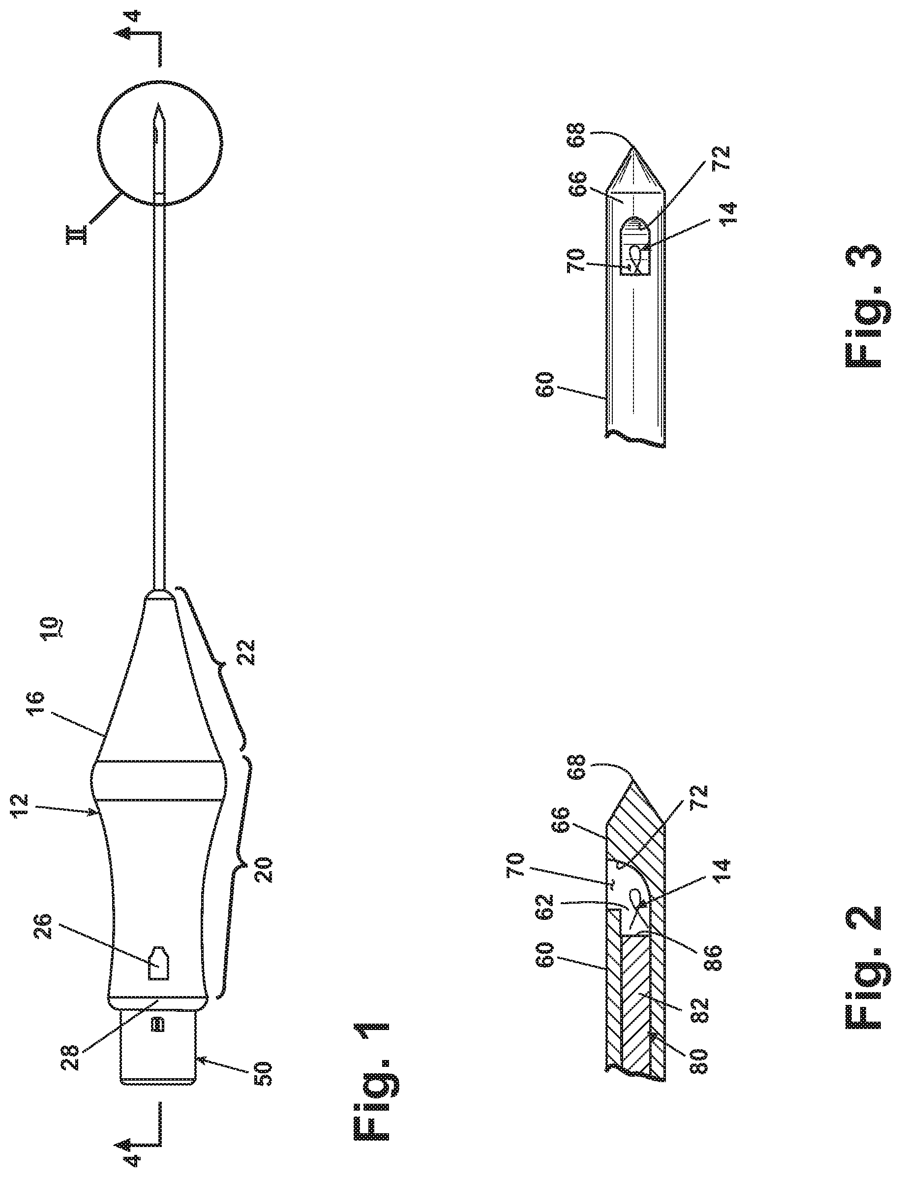
FIG. 1 is a plan view of a self-contained, self-piercing, and side-expelling marking apparatus comprising an actuator, a cannula with a side opening, and a stylet for laterally expelling a marker through the side opening in accordance with the invention.
FIG. 2 is an enlarged sectional view of the area II of FIG. 1, illustrating the relationship between the cannula, stylet and marker prior to the expelling of the marker.
FIG. 3. is an enlarged top view of the cannula tip of FIG. 2.
FIG. 4. is an enlarged sectional view of a portion of the actuator.
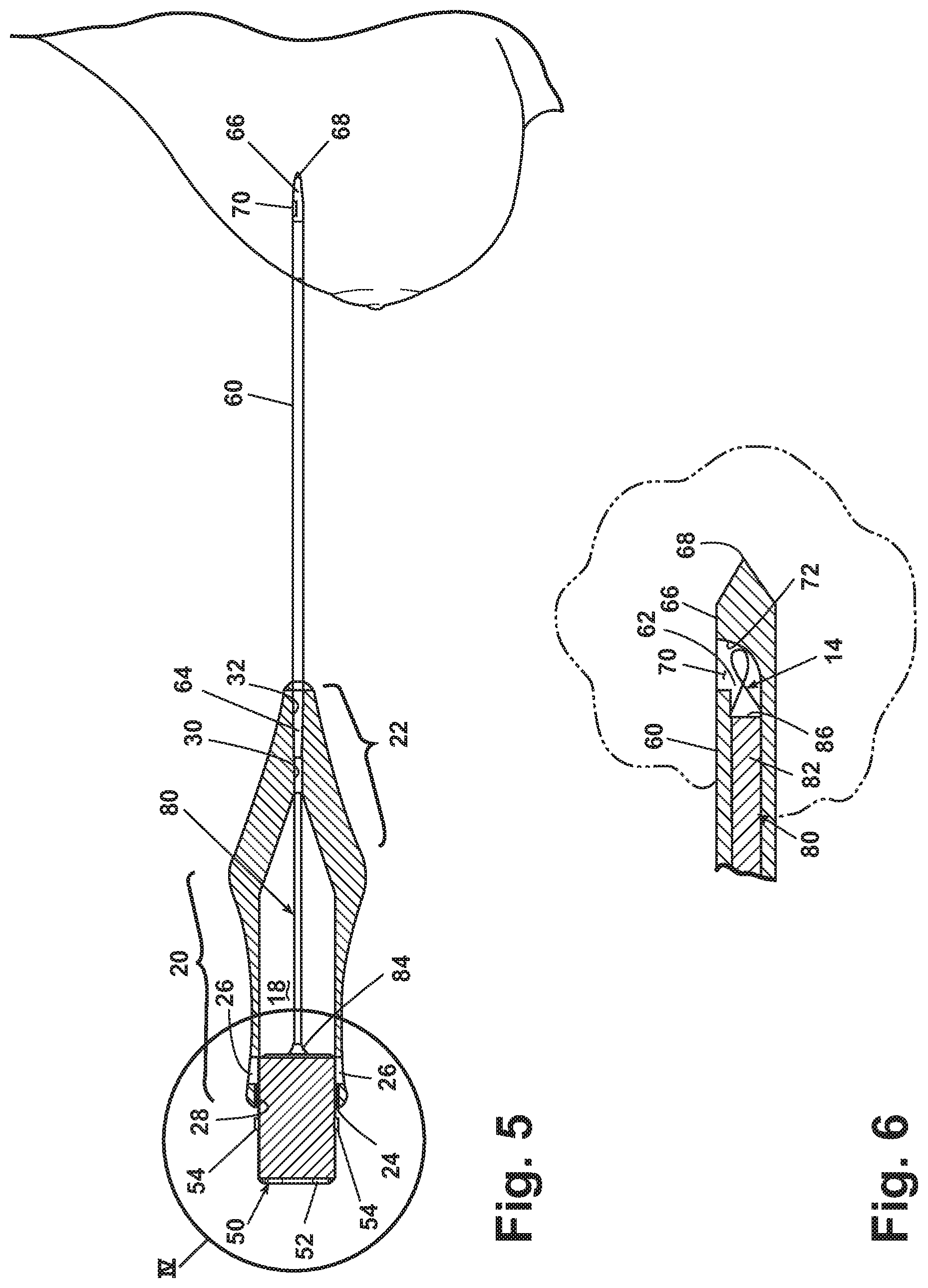
FIG. 5 is a sectional view of the marking device inserted into a tissue mass such that the cannula side opening is adjacent an area to be marked, with the stylet shown in a ready position and the marker still retained within the cannula lumen.
FIG. 6 is an enlarged sectional view of the cannula tip of FIG. 5.
FIG. 7 is a sectional view of the marking device inserted into a tissue mass such that the cannula side opening is adjacent an area to be marked, with the stylet shown in a expelled position and the marker expelled through the side opening into the surrounding tissue mass.
FIG. 8 is an enlarged sectional view of the cannula tip of FIG. 7.
FIG. 9 is a sectional view of an alternative design for the cannula and stylet according to the invention, with the stylet having a flexible tip and shown in the ready position.
FIG. 10 is a sectional view of the cannula and stylet of FIG. 9 with the stylet shown in the expelled position.
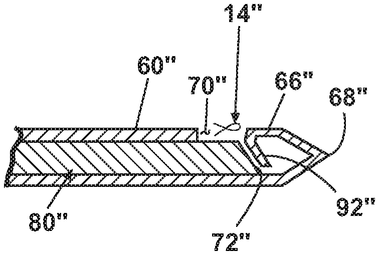
FIG. 11 is a sectional view of a second alternative design for the cannula and stylet according to the invention, with the stylet having a ramped tip and shown in the expelled position.
DETAILED DESCRIPTION
FIGS. 1-4 illustrate a self-contained, self-penetrating, side-expelling marking apparatus 10 according to the invention, which is capable of the percutaneous placement of a imaging marker at a desired location, such as at a tissue biopsy site or a lesion site in a breast. The marking apparatus 10 comprises an introducer 12 and an imaging marker 14 (FIG. 2) contained within the introducer 12. The introducer 12 includes an actuator 16 having a hollow interior 18. The actuator 16 comprises a grip portion 20 from which extends a tapered nose portion 22. The grip portion 20 defines a rear opening 24 that provides access to the hollow interior 18. A pair of detents 26 are formed in the grip portion 20 near the rear opening 24. Channels 28 are formed on the interior surface of the grip portion 20 and extend from the rear opening 24 to the detents 26.
The nose portion 22 comprises a guide passage 30 extending from the tip of the nose portion 22 to the hollow interior 18 of the actuator 16. The guide passage 30 decreases in diameter inwardly from the tip of the nose portion to form a cannula seat 32 (FIG. 5).
A plunger 50 comprises a cylindrical body 52 from which extend a pair of catches 54 at diametrically opposed positions. The cylindrical body 52 is sized so that it is slidably received within the rear opening 24 of the actuator 16 where it is so oriented with respect to the actuator such that the catches 54 are aligned with the guide channels 28. The plunger is free to reciprocate within the grip portion 20 of the actuator 16.
A cannula 60 is mounted to the introducer 12. The cannula 60 defines a hollow interior in the form of a lumen 62 and comprises a proximal end 64 and a distal end 66. The proximal end 64 (FIG. 5) is mounted within the cannula seat 32 to secure the cannula 60 to the introducer 12. The distal end 66 terminates in a closed-off tip 68 to provide the marking apparatus with self-piercing functionality. The closed-off tip 68 is illustrated as being pointed, but other suitable shapes are possible.
The cannula 60 is preferably 13 gage or less in size. The cannula 60 is also preferably rigid. That is, the cannula does not substantially flex. The rigidity of the cannula aids in inserting the cannula into a tissue mass, without the aid of a guide needle or guide cannula.
A side opening 70 is formed in the cannula 60 and extends entirely through the cannula such that the lumen 62 is in communication with the exterior of the cannula 60 through the side opening 70. The side opening is preferably located behind the closed-off tip 68.
A ramp 72 is provided on the interior of the cannula 60. The ramp 72 is illustrated as being integrally formed with the closed-off tip 68. Such a configuration can result in a solid distal end 66 as illustrated. However, the distal end can be hollow and the ramp 72 can be formed by separately from the distal end 66.
The ramp 72 extends diametrically across the lumen 62 and terminates at the side opening 70. With this configuration, the ramp 72 aids in directing an imaging marker 14 stored in the lumen through the side opening 70 and beyond the exterior of the cannula.
A stylet 80 comprising a shaft 82 and a base 84 is received within the hollow interior 18 of the actuator 16 in a manner such that the shaft 82 extends through the guide passage 30 and into the cannula interior 62 and the stylet base 84 lies within the hollow interior 18 and is mounted to the plunger 50. Thus, the reciprocation of the plunger 50 relative to the grip portion 20 results in a reciprocation of the stylet 80 within the cannula 60.
The stylet 80 terminates in a distal end 86, which, when the marking apparatus is in the ready position, is spaced from the distal end 66 of the cannula 60 to form a marker recess therebetween. As illustrated, a single marker 14 is stored within the marker recess. It is within the scope of the invention for multiple markers to be received within the marker recess.
As is shown, the foregoing construction provides a marking apparatus that is preassembled as a self-contained unit and prepackaged, all under sterile conditions, thereby affording the practitioner substantially greater convenience and reliability, while eliminating the need for sterilizing the self-contained unit after use. Preferably, the self-contained unit is disposed of after it is used.
Referring to FIGS. 5-8, in operation, the introducer 12 begins in the ready condition shown in FIGS. 5 and 6. In this condition, the distal end 86 of the stylet 80 is received within the cannula and spaced from the closed-off distal end 66 of the cannula to define a marker recess in which a marker 14 is stored. The plunger 50 is in a position relative to the grip portion 20 in which the catches are outside the grip portion; that is, they are not received within the detents 26. However, the plunger 50 is so oriented with respect to the grip portion that the catches 54 are aligned with the guide channels 28.
With the introducer in the ready condition, the cannula is positioned within the tissue mass such that the side opening 70 is at or near the location of a tissue mass where it is desired to place the marker. In the case of marking a biopsy site, the side opening is preferably placed adjacent the biopsy site.
To place the side opening adjacent the site to be marked, the medical professional grasps the grip portion 20 of the actuator and presses the closed-off tip 68 against the exterior of the tissue mass to puncture the tissue mass. The medical professional continues applying force to the grip portion 20 to drive the cannula 60 to the desired location within the tissue mass.
The closed tip 68 helps separate the tissue of the tissue mass to make it easier to insert the cannula within the tissue mass to the desired location. A starter incision can be made in the exterior of the tissue mass to reduce the initial force need to start the insertion.
The used of a side opening 70 instead of a tip opening found in the prior art self-contained devices helps prevent the accumulation of tissue within the lumen 62 upon the insertion of the cannula 60 into the tissue mass. The closed tip 68 also helps in that it separates the tissue to form a path through which the side opening passes. Since the side opening is parallel to the path, there is much less tendency for the insertion of the cannula to force tissue into the side opening as could occur in the prior-art front opening cannulae.
Typically, a suitable imaging system will be used by the medical professional to help guide the cannula to the desired location within the tissue mass. Examples of contemporary imaging systems include: stereotactic, x-ray, ultrasound, CAT scan, or MRI. The invention is not limited to any particular type of imaging system.
Once the cannula is positioned at the desired location, the plunger 50 is moved from a first or ready condition as illustrated in FIGS. 5 and 6 to a second or expelled condition as illustrated in FIGS. 7 and 8. As the plunger is moved, the stylet 80 is advanced into the marker recess to drive the marker 14 up the ramp 72. The continued advancement of the stylet 80 ultimately drives the marker 14 through the side opening 70 and into the adjacent tissue.
Once the stylet is in the expelled position, the cannula can be withdrawn to leave the marker in the tissue. To withdraw the cannula, the medical professional pulls on the actuator to withdraw the cannula from the tissue mass. After use, the marking apparatus is disposed of, negating the need for sterilization.
As illustrated, the rigid cannula in combination with the closed-off tip 68 provides an ideal structure for inserting the device directly into the tissue without the need for a guide needle or cannula. This is advantageous in that it reduces the size of the opening formed in the tissue and thereby reducing the trauma to the patient. The closed-off tip is used to puncture the exterior of the tissue mass. While the marking apparatus of the invention can be used with a guide needle or cannula, there is no need to do so because of the self-piercing nature of the invention.
FIGS. 9 and 10 illustrate an alternative design for the stylet in the ready and expelled conditions, respectively. The alternative stylet 80' is essentially identical to the stylet 80, except that the distal end 66' is made from a resilient material and has an angled surface 90'. The resilient material permits the distal end 66' to deflect when contacting the ramp 72', such that the distal end 66' generally follows the shape of the ramp 72'. The angle of the angled surface 90' is preferably selected such that the angled surface substantially closes off the side opening 70' when the stylet is in the expelled condition, which will ensure that the marker is completely expelled through the side opening 70'. It will also ensure that no portion of the marker 14 will be pulled back into the side opening 70' due to the vacuum forces created upon the withdrawal of the cannula. The angled surface 90' functions like the ramp 72 in that it helps to deflect the marker 14 through the side opening.
FIG. 11 illustrates another alternative design for the stylet and cannula. In this alternative design, the distal end 66'' of the stylet 80'' includes a ramp 72''. A resilient end wall 92'' is used instead of the ramp 72 of the cannula. The space between the ramp 72'' and the resilient end wall 92'' defines the marker recess in which multiple markers 14'' are stored. The advancement of the stylet from the ready condition to the expelled condition drives the markers up the ramp 72''. When contacted by the ramp 72'', the resilient end wall 92'' deflects to permit the ramp 72'' to slide beneath and into the distal end closed tip 68'' of the cannula.
In all of the embodiments, multiple markers can be located within the cannula and expelled at the same or different locations within the tissue mass.
While the invention has been specifically described in connection with certain specific embodiments thereof, it is to be understood that this is by way of illustration and not of limitation, and the scope of the appended claims should be construed as broadly as the prior art will permit.
* * * * *
References
D00000
D00001
D00002
D00003
D00004
D00005
XML
uspto.report is an independent third-party trademark research tool that is not affiliated, endorsed, or sponsored by the United States Patent and Trademark Office (USPTO) or any other governmental organization. The information provided by uspto.report is based on publicly available data at the time of writing and is intended for informational purposes only.
While we strive to provide accurate and up-to-date information, we do not guarantee the accuracy, completeness, reliability, or suitability of the information displayed on this site. The use of this site is at your own risk. Any reliance you place on such information is therefore strictly at your own risk.
All official trademark data, including owner information, should be verified by visiting the official USPTO website at www.uspto.gov. This site is not intended to replace professional legal advice and should not be used as a substitute for consulting with a legal professional who is knowledgeable about trademark law.