Miniaturized microwave ablation assembly
Brannan October 27, 2
U.S. patent number 10,813,691 [Application Number 14/503,926] was granted by the patent office on 2020-10-27 for miniaturized microwave ablation assembly. This patent grant is currently assigned to COVIDIEN LP. The grantee listed for this patent is Covidien LP. Invention is credited to Joseph D Brannan.


View All Diagrams
| United States Patent | 10,813,691 |
| Brannan | October 27, 2020 |
Miniaturized microwave ablation assembly
Abstract
Microwave applicators are disclosed which include a first transmission line segment, a second transmission line segment, and a third transmission line segment. The first transmission line segment includes a first inner conductor, a first dielectric disposed on the first inner conductor, and a first outer conductor disposed on the first dielectric. The second transmission line segment includes a second inner conductor, a second dielectric disposed on the second inner conductor, and a second outer conductor disposed on the second dielectric. The third transmission line segment includes a third inner conductor disposed on the third inner conductor, a third outer conductor disposed on the proximal end of the third dielectric. The impedance looking into the second transmission line segment from the first transmission line segment can be adjusted by adjusting the length of the third transmission line segment.
| Inventors: | Brannan; Joseph D (Erie, CO) | ||||||||||
|---|---|---|---|---|---|---|---|---|---|---|---|
| Applicant: |
|
||||||||||
| Assignee: | COVIDIEN LP (Mansfield,
MA) |
||||||||||
| Family ID: | 1000005139624 | ||||||||||
| Appl. No.: | 14/503,926 | ||||||||||
| Filed: | October 1, 2014 |
Prior Publication Data
| Document Identifier | Publication Date | |
|---|---|---|
| US 20160095657 A1 | Apr 7, 2016 | |
| Current U.S. Class: | 1/1 |
| Current CPC Class: | A61B 18/1815 (20130101); A61B 2018/00023 (20130101); A61B 2018/00577 (20130101); A61B 2018/1861 (20130101) |
| Current International Class: | A61B 18/18 (20060101); A61B 18/00 (20060101) |
References Cited [Referenced By]
U.S. Patent Documents
| D223367 | April 1972 | Kountz |
| 4161704 | July 1979 | Schafer |
| D263020 | February 1982 | Rau, III |
| D266842 | November 1982 | Villers et al. |
| D278306 | April 1985 | McIntosh |
| 4583589 | April 1986 | Kasevich |
| D295893 | May 1988 | Sharkany et al. |
| D295894 | May 1988 | Sharkany et al. |
| 5301687 | April 1994 | Wong et al. |
| 5364392 | November 1994 | Warner et al. |
| 5370644 | December 1994 | Langberg |
| 5370676 | December 1994 | Sozanski et al. |
| D354218 | January 1995 | Van de Peer |
| 5545137 | August 1996 | Rudie et al. |
| 5603697 | February 1997 | Grundy et al. |
| 5624392 | April 1997 | Saab |
| 5685839 | November 1997 | Edwards et al. |
| 5693082 | December 1997 | Warner et al. |
| 5741249 | April 1998 | Moss et al. |
| 5861021 | January 1999 | Thome et al. |
| 5980505 | November 1999 | Wilson |
| 5993447 | November 1999 | Blewett et al. |
| 5995875 | November 1999 | Blewett et al. |
| 6014581 | January 2000 | Whayne et al. |
| D424693 | May 2000 | Pruter |
| D424694 | May 2000 | Tetzlaff et al. |
| D425201 | May 2000 | Tetzlaff et al. |
| 6061551 | May 2000 | Sorrells et al. |
| 6106524 | August 2000 | Eggers et al. |
| 6117101 | September 2000 | Diederich et al. |
| 6139527 | October 2000 | Laufer et al. |
| 6186978 | February 2001 | Samson et al. |
| 6210367 | April 2001 | Carr |
| 6222500 | April 2001 | Koitsalu |
| 6235024 | May 2001 | Tu |
| 6277113 | August 2001 | Berube |
| D449886 | October 2001 | Tetzlaff et al. |
| 6355016 | March 2002 | Bagaoisan et al. |
| D457958 | May 2002 | Dycus et al. |
| D457959 | May 2002 | Tetzlaff et al. |
| 6398781 | June 2002 | Goble et al. |
| 6427089 | July 2002 | Knowlton |
| 6485486 | November 2002 | Trembly et al. |
| 6496737 | December 2002 | Rudie et al. |
| 6496738 | December 2002 | Carr |
| 6514249 | February 2003 | Maguire et al. |
| 6547788 | April 2003 | Maguire et al. |
| 6575969 | June 2003 | Rittman, III et al. |
| 6599288 | July 2003 | Maguire et al. |
| 6629974 | October 2003 | Penny et al. |
| 6635055 | October 2003 | Cronin |
| 6652515 | November 2003 | Maguire et al. |
| 6676657 | January 2004 | Wood |
| D487039 | February 2004 | Webster et al. |
| 6689127 | February 2004 | Gough et al. |
| 6706040 | March 2004 | Mahon et al. |
| 6723091 | April 2004 | Goble et al. |
| 6740108 | May 2004 | Just et al. |
| 6770070 | August 2004 | Balbierz |
| 6780183 | August 2004 | Jimenez, Jr. et al. |
| D496997 | October 2004 | Dycus et al. |
| D499181 | November 2004 | Dycus et al. |
| 6847848 | January 2005 | Sterzer et al. |
| 6869431 | March 2005 | Maguire et al. |
| 6893436 | May 2005 | Woodard et al. |
| 6932776 | August 2005 | Carr |
| 6997925 | February 2006 | Maguire et al. |
| 7004938 | February 2006 | Ormsby et al. |
| 7047068 | May 2006 | Haissaguerre |
| 7049068 | May 2006 | Thorp et al. |
| D525361 | July 2006 | Hushka |
| 7089063 | August 2006 | Lesh et al. |
| 7113832 | September 2006 | Longo |
| D531311 | October 2006 | Guerra et al. |
| D533942 | December 2006 | Kerr et al. |
| D535027 | January 2007 | James et al. |
| 7194297 | March 2007 | Talpade et al. |
| 7197356 | March 2007 | Carr |
| D541418 | April 2007 | Schechter et al. |
| 7200445 | April 2007 | Dalbec et al. |
| D541938 | May 2007 | Kerr et al. |
| 7261001 | August 2007 | Heijnsdijk et al. |
| 7263398 | August 2007 | Carr |
| 7275547 | October 2007 | Willis |
| 7285116 | October 2007 | de la Rama et al. |
| 7294125 | November 2007 | Phalen et al. |
| 7300436 | November 2007 | Penny et al. |
| 7303558 | December 2007 | Swanson |
| D564662 | March 2008 | Moses et al. |
| 7402168 | July 2008 | Sanderson et al. |
| 7410486 | August 2008 | Fuimaono et al. |
| D576932 | September 2008 | Strehler |
| 7438712 | October 2008 | Chouinard |
| 7460898 | December 2008 | Brister et al. |
| 7507229 | March 2009 | Hewitt et al. |
| D594736 | June 2009 | Esjunin |
| D594737 | June 2009 | Kelly et al. |
| 7608056 | October 2009 | Kennedy, II |
| 7611508 | November 2009 | Yang et al. |
| D606203 | December 2009 | Husheer et al. |
| D613412 | April 2010 | DeCarlo |
| 7697972 | April 2010 | Verard et al. |
| 7706894 | April 2010 | Stewart et al. |
| 7713259 | May 2010 | Gosiengfiao et al. |
| 7722604 | May 2010 | Brown, III et al. |
| 7734330 | June 2010 | Carr |
| 7769469 | August 2010 | Carr et al. |
| 7824392 | November 2010 | Zhou |
| 7826904 | November 2010 | Appling et al. |
| 7833218 | November 2010 | Lunn et al. |
| D634010 | March 2011 | DeCarlo |
| 7921855 | April 2011 | Danek et al. |
| 7933660 | April 2011 | Carr |
| 7993351 | August 2011 | Worley et al. |
| 8021351 | September 2011 | Boldenow et al. |
| 8075532 | December 2011 | Kassab et al. |
| 8182466 | May 2012 | Stehr et al. |
| 8206373 | June 2012 | Zhou |
| 8206380 | June 2012 | Lenihan et al. |
| 8226566 | July 2012 | Nita |
| 8277438 | October 2012 | Griffin et al. |
| 8289551 | October 2012 | Wu |
| 8292881 | October 2012 | Brannan et al. |
| 8328799 | December 2012 | Brannan |
| 8328800 | December 2012 | Brannan |
| 8328801 | December 2012 | Brannan |
| 8340740 | December 2012 | Holzer et al. |
| 8343145 | January 2013 | Brannan |
| 8394092 | March 2013 | Brannan |
| 8412306 | April 2013 | Kurpad et al. |
| D681810 | May 2013 | DeCarlo |
| 8515554 | August 2013 | Carr |
| 8574227 | November 2013 | Hancock et al. |
| 8655454 | February 2014 | Prakash et al. |
| 8672932 | March 2014 | van der Weide et al. |
| 8795268 | August 2014 | Willyard |
| 2002/0022836 | February 2002 | Goble et al. |
| 2002/0026187 | February 2002 | Swanson |
| 2003/0191451 | October 2003 | Gilmartin |
| 2004/0049254 | March 2004 | Longo |
| 2004/0243200 | December 2004 | Turner et al. |
| 2005/0176292 | August 2005 | Lee et al. |
| 2005/0215942 | September 2005 | Abrahamson et al. |
| 2005/0245920 | November 2005 | Vitullo et al. |
| 2006/0004351 | January 2006 | Arless et al. |
| 2006/0009833 | January 2006 | Chobotov et al. |
| 2006/0089637 | April 2006 | Werneth et al. |
| 2006/0167416 | July 2006 | Mathis et al. |
| 2006/0189973 | August 2006 | van der Weide |
| 2006/0241564 | October 2006 | Corcoran et al. |
| 2006/0253102 | November 2006 | Nance et al. |
| 2007/0088319 | April 2007 | Martone |
| 2007/0287912 | December 2007 | Khuri-Yakub et al. |
| 2008/0033424 | February 2008 | van der Weide et al. |
| 2008/0091169 | April 2008 | Heideman et al. |
| 2008/0147056 | June 2008 | van der Weide et al. |
| 2008/0208039 | August 2008 | Kurpad et al. |
| 2008/0228167 | September 2008 | Mittermeyer et al. |
| 2008/0255507 | October 2008 | Mushtaha |
| 2009/0076409 | March 2009 | Wu et al. |
| 2009/0187180 | July 2009 | Brannan |
| 2009/0222002 | September 2009 | Bonn et al. |
| 2009/0234220 | September 2009 | Maschke |
| 2010/0036369 | February 2010 | Hancock |
| 2010/0262134 | October 2010 | Jensen et al. |
| 2010/0268196 | October 2010 | Hastings et al. |
| 2011/0004205 | January 2011 | Chu et al. |
| 2011/0118723 | May 2011 | Turner et al. |
| 2011/0130750 | June 2011 | Ormsby et al. |
| 2011/0166518 | July 2011 | Nguyen et al. |
| 2011/0166519 | July 2011 | Nguyen et al. |
| 2011/0282336 | November 2011 | Brannan et al. |
| 2011/0301587 | December 2011 | Deem et al. |
| 2012/0065481 | March 2012 | Hunter et al. |
| 2012/0071822 | March 2012 | Roma et al. |
| 2012/0078175 | March 2012 | Vreeman |
| 2012/0078230 | March 2012 | Lowe et al. |
| 2012/0172860 | July 2012 | Brannan |
| 2012/0232619 | September 2012 | Turovskiy et al. |
| 2012/0259326 | October 2012 | Brannan et al. |
| 2012/0277730 | November 2012 | Salahieh et al. |
| 2013/0137977 | May 2013 | Eder |
| 2013/0178841 | July 2013 | Reid, Jr. |
| 2013/0197481 | August 2013 | Guo et al. |
| 2013/0197482 | August 2013 | Akitomo |
| 2013/0237980 | September 2013 | Brannan |
| 2013/0241769 | September 2013 | Brannan et al. |
| 2013/0245624 | September 2013 | Bahney |
| 2013/0253500 | September 2013 | Lee et al. |
| 2013/0261617 | October 2013 | Podhajsky |
| 2013/0261620 | October 2013 | Brannan et al. |
| 2013/0267946 | October 2013 | Brannan et al. |
| 2013/0289560 | October 2013 | DeCarlo et al. |
| 2013/0296841 | November 2013 | Brannan |
| 2013/0304057 | November 2013 | Rossetto |
| 2013/0317407 | November 2013 | Reid, Jr. et al. |
| 2013/0317495 | November 2013 | Brannan |
| 2013/0317499 | November 2013 | Brannan et al. |
| 2013/0324910 | December 2013 | Ohri et al. |
| 2013/0324911 | December 2013 | Ohri et al. |
| 2013/0338661 | December 2013 | Behnke, II |
| 2013/0345541 | December 2013 | Nau, Jr. |
| 2013/0345551 | December 2013 | Arts et al. |
| 2013/0345552 | December 2013 | Arts et al. |
| 2013/0345553 | December 2013 | Arts et al. |
| 2013/0345699 | December 2013 | Brannan et al. |
| 2014/0000098 | January 2014 | Dunning et al. |
| 2014/0005655 | January 2014 | Brannan |
| 2014/0005657 | January 2014 | Brannan et al. |
| 2014/0018668 | January 2014 | Zheng et al. |
| 2014/0018677 | January 2014 | Sharonov |
| 2014/0018793 | January 2014 | Sharonov |
| 2014/0052125 | February 2014 | Bra et al. |
| 2014/0094789 | April 2014 | Brannan |
| 2014/0094792 | April 2014 | Sharonov |
| 2014/0094794 | April 2014 | Orszulak |
| 2014/0094797 | April 2014 | Brannan |
| 2014/0290830 | October 2014 | Brannan |
| 2015/0022342 | January 2015 | Will et al. |
| 1103807 | Jun 1995 | CN | |||
| 102570009 | Jul 2012 | CN | |||
| 102711643 | Oct 2012 | CN | |||
| 390937 | Mar 1924 | DE | |||
| 1099658 | Feb 1961 | DE | |||
| 1139927 | Nov 1962 | DE | |||
| 1149832 | Jun 1963 | DE | |||
| 1439302 | Jan 1969 | DE | |||
| 2439587 | Feb 1975 | DE | |||
| 2455174 | May 1975 | DE | |||
| 2407559 | Aug 1975 | DE | |||
| 2415263 | Oct 1975 | DE | |||
| 2429021 | Jan 1976 | DE | |||
| 2460481 | Jun 1976 | DE | |||
| 2602517 | Jul 1976 | DE | |||
| 2504280 | Aug 1976 | DE | |||
| 2627679 | Jan 1977 | DE | |||
| 2540968 | Mar 1977 | DE | |||
| 2820908 | Nov 1978 | DE | |||
| 2803275 | Aug 1979 | DE | |||
| 2823291 | Nov 1979 | DE | |||
| 2946728 | May 1981 | DE | |||
| 3143421 | May 1982 | DE | |||
| 3045996 | Jul 1982 | DE | |||
| 3120102 | Dec 1982 | DE | |||
| 3510586 | Oct 1986 | DE | |||
| 3604823 | Aug 1987 | DE | |||
| 8712328 | Feb 1988 | DE | |||
| 3711511 | Jun 1988 | DE | |||
| 3904558 | Aug 1990 | DE | |||
| 3942998 | Jul 1991 | DE | |||
| 4238263 | May 1993 | DE | |||
| 04303882 | Feb 1995 | DE | |||
| 4339049 | May 1995 | DE | |||
| 29616210 | Nov 1996 | DE | |||
| 19608716 | Apr 1997 | DE | |||
| 19751106 | May 1998 | DE | |||
| 19717411 | Nov 1998 | DE | |||
| 19751108 | May 1999 | DE | |||
| 19801173 | Jul 1999 | DE | |||
| 19848540 | May 2000 | DE | |||
| 10224154 | Dec 2003 | DE | |||
| 10310765 | Sep 2004 | DE | |||
| 10328514 | Mar 2005 | DE | |||
| 102004022206 | Dec 2005 | DE | |||
| 202005015147 | Feb 2006 | DE | |||
| 102009015699 | May 2010 | DE | |||
| 0 246 350 | Nov 1987 | EP | |||
| 0 521 264 | Jan 1993 | EP | |||
| 0 556 705 | Aug 1993 | EP | |||
| 0 558 429 | Sep 1993 | EP | |||
| 0 648 515 | Apr 1995 | EP | |||
| 0 836 868 | Apr 1998 | EP | |||
| 0 882 955 | Dec 1998 | EP | |||
| 1034747 | Sep 2000 | EP | |||
| 1034748 | Sep 2000 | EP | |||
| 1055400 | Nov 2000 | EP | |||
| 1 159 926 | Dec 2001 | EP | |||
| 2147651 | Jan 2010 | EP | |||
| 2322113 | May 2011 | EP | |||
| 179 607 | Nov 1906 | FR | |||
| 1 275 415 | Nov 1961 | FR | |||
| 1 347 865 | Jan 1964 | FR | |||
| 2 235 669 | Jan 1975 | FR | |||
| 2 276 027 | Jan 1976 | FR | |||
| 2 313 708 | Dec 1976 | FR | |||
| 2 502 935 | Oct 1982 | FR | |||
| 2 517 953 | Jun 1983 | FR | |||
| 2 573 301 | May 1986 | FR | |||
| 2 862 813 | May 2005 | FR | |||
| 2 864 439 | Jul 2005 | FR | |||
| 5-5106 | Jan 1993 | JP | |||
| 05-40112 | Feb 1993 | JP | |||
| 06343644 | Dec 1994 | JP | |||
| 07265328 | Oct 1995 | JP | |||
| 08056955 | Mar 1996 | JP | |||
| 08252263 | Oct 1996 | JP | |||
| 09000492 | Jan 1997 | JP | |||
| 09010223 | Jan 1997 | JP | |||
| 11244298 | Sep 1999 | JP | |||
| 2000342599 | Dec 2000 | JP | |||
| 2000350732 | Dec 2000 | JP | |||
| 2001003776 | Jan 2001 | JP | |||
| 2001008944 | Jan 2001 | JP | |||
| 2001029356 | Feb 2001 | JP | |||
| 2001037775 | Feb 2001 | JP | |||
| 2001128990 | May 2001 | JP | |||
| 2001231870 | Aug 2001 | JP | |||
| 2008142467 | Jun 2008 | JP | |||
| 2013511348 | Apr 2013 | JP | |||
| 20070093068 | Sep 2007 | KR | |||
| 20100014406 | Feb 2010 | KR | |||
| 20120055063 | May 2012 | KR | |||
| 166452 | Nov 1964 | SU | |||
| 401367 | Oct 1973 | SU | |||
| 727201 | Apr 1980 | SU | |||
| 94/16632 | Aug 1994 | WO | |||
| 97/24074 | Jul 1997 | WO | |||
| 00/36985 | Jun 2000 | WO | |||
| 0057811 | Oct 2000 | WO | |||
| 0100114 | Jan 2001 | WO | |||
| 02/45790 | Jun 2002 | WO | |||
| 2008/068485 | Jun 2008 | WO | |||
| 20101035831 | Apr 2010 | WO | |||
| 2014025551 | Feb 2014 | WO | |||
| 2014160931 | Oct 2014 | WO | |||
Other References
|
LigaSureTM Vessel Sealing System, the Seal of Confidence in General , Gynecologic, Urologic, and Laparaoscopic Surgery, Sales/Product Literature, Jan. 2004. cited by applicant . Livraghi et al., (1995) "Saline-enhanced RF Tissue Ablation in the Treatment of Liver Metastases", Radiology, p. 140 (Abstr). cited by applicant . Lyndon B. Johnson Space Center, Houston, Texas, "Compact Directional Microwave Antenna for Localized Heating," NASA Tech Briefs, Mar. 2008. cited by applicant . M. A. Astrahan, "A Localized Current Field Hyperthermia System for Use with 192-Iridium Interstitial Implants" Medical Physics. 9(3), May/Jun. 1982. cited by applicant . Magdy F. Iskander et al., "Design Optimization of Interstitial Antennas", IEEE Transactions on Biomedical Engineering, vol. 36, No. 2, Feb. 1989, pp. 238-246. cited by applicant . McGahan et al., (1995) "Percutaneous Ultrasound-guided Radiofrequency Electrocautery Ablation of Prostate Tissue in Dogs", Acad Radiol, vol. 2, No. 1: pp. 61-65. cited by applicant . McLellan et al., "Vessel Sealing for Hemostasis During Pelvic Surgery" Int'l Federation of Gynecology and Obstetrics FIGO World Congress 2000, Washington, DC. cited by applicant . MDTECH product literature (Dec. 1999) "FlexStrand": product description, 1 page. cited by applicant . MDTECH product literature (Mar. 2000) I'D Wire: product description, 1 page. cited by applicant . Medtrex Brochure "The O.R. Pro 300" 1 page, Sep. 1998. cited by applicant . Michael Choti, "Abdominoperineal Resection with the LigaSureTM Vessel Sealing System and LigaSureTM Atlas 20 cm Open Instrument" Innovations That Work, Jun. 2003. cited by applicant . Muller et al., "Extended Left Hemicolectomy Using the LigaSureTM Vessel Sealing System" Innovations That Work. LJ, Sep. 1999. cited by applicant . Murakami, R. et al., (1995). "Treatment of Hepatocellular Carcinoma: Value of Percutaneous Microwave Coagulation," American Journal of Radiology (AJR) 164:1159-1164. cited by applicant . Ni Wei et al., "A Signal Processing Method for the Coriolis Mass Flowmeter Based on a Normalized . . . " Journal of Applied Sciences-Yingyong Kexue Xuebao, Shangha CN, vol. 23, No. 2:(Mar. 2005); pp. 160-184. cited by applicant . Ogden, "Goertzel Alternative to the Fourier Transform" Jun. 1993 pp. 485-487 Electronics World; Reed Business Publishing, Sutton, Surrey, BG, vol. 99, No. 9, 1687. cited by applicant . Olsson M.D. et al., "Radical Cystectomy in Females" Current Surgical Techniques in Urology, vol. 14, Issue 3, 2001. cited by applicant . Organ, L W., "Electrophysiologic Principles of Radiofrequency Lesion Making" Appl. Neurophysiol, vol. 39: pp. 69-76 (1976/77). cited by applicant . P.R. Stauffer et al., "Interstitial Heating Technologies", Thermoradiotheray and Thermochemotherapy (1995) vol. I, Biology, Physiology, Physics, pp. 279-320. cited by applicant . Palazzo et al., "Randomized clinical trial of LigaSureTM versus open haemorrhoidectomy" British Journal of Surgery 2002,89,154-157 "Innovations in Electrosurgery" Sales/Product Literature; Dec. 31, 2000. cited by applicant . Paul G. Horgan, "A Novel Technique for Parenchymal Division During Hepatectomy" The American Journal of Surgery, vol. 181, No. 3, Apr. 2001, pp. 236-237. cited by applicant . Peterson et al., "Comparison of Healing Process Following Ligation with Sutures and Bipolar Vessel Sealing" Surgical Technology International (2001). cited by applicant . R. Gennari et al., (Jun. 2000) "Use of Technetium-99m-Labeled Colloid Albumin for Preoperative and Intraoperative Localization of Non palpable Breast Lesions," American College of Surgeons. 190(6):692-699. cited by applicant . Valleylab Brochure, "Reducing Needlestick Injuries in the Operating Room" 1 page, Mar. 2001. cited by applicant . Reidenbach, (1995) "First Experimental Results with Special Applicators for High-Frequency Interstitial Thermotherapy", Society Minimally Invasive Therapy, 4(Suppl 1):40 (Abstr). cited by applicant . Richard Wolf Medical Instruments Corp. Brochure, "Kleppinger Bipolar Forceps & Bipolar Generator" 3 pages, Jan. 1989. cited by applicant . Rothenberg et al., "Use of the LigaSureTM Vessel Sealing System in Minimally Invasive Surgery in Children" Int'l Pediatric Endosurgery Group (I PEG) 2000. cited by applicant . Sayfan et al., "Sutureless Closed Hemorrhoidectomy: A New Technique" Annals of Surgery, vol. 234, No. 1, Jul. 2001, pp. 21-24. cited by applicant . Sengupta et al., "Use of a Computer-Controlled Bipolar Diathermy System in Radical Prostatectomies and Other Open Urological Surgery" ANZ Journal of Surgery (2001) 71.9 pp. 538-540. cited by applicant . Sigel et al., "The Mechanism of Blood Vessel Closure by High Frequency Electrocoagulation" Surgery Gynecology & Obstetrics, Oct. 1965 pp. 823-831. cited by applicant . Solbiati et al., (2001) "Percutaneous Radio-frequency Ablation of Hepatic Metastases from Colorectal Cancer: Long-term Results in 117 Patients", Radiology, vol. 221, pp. 159-166. cited by applicant . Solbiati et al. (1995) "Percutaneous US-guided RF Tissue Ablation of Liver Metastases: Long-term Follow-up", Radiology, pp. 195-203. cited by applicant . Strasberg et al., "Use of a Bipolar Vassel-Sealing Device for Parenchymal Transection During Liver Surgery" Journal of Gastrointestinal Surgery, vol. 6, No. 4, Jul./Aug. 2002 pp. 569-574. cited by applicant . Sugita et al., "Bipolar Coagulator with Automatic Thermocontrol" J. Neurosurg., vol. 41, Dec. 1944, pp. 777-779. cited by applicant . Sylvain Labonte et al., "Monopole Antennas for Microwave Catheter Ablation", IEEE Trans. on Microwave Theory and Techniques, vol. 44, No. 10, pp. 1832-1840, Oct. 1995. cited by applicant . T. Matsukawa et al., "Percutaneous Microwave Coagulation Therapy in Liver Tumors", Acta Radiologica, vol. 38, pp. 410-415, 1997. cited by applicant . T. Seki et al., (1994) "Ultrasonically Guided Percutaneous Microwave Coagulation Therapy for Small Hepatocellular Carcinoma," Cancer 74(3):817-825. cited by applicant . Urologix, Inc.--Medical Professionals: TargisTM Technology (Date Unknown). "Overcoming the Challenge" located at: <http://www.urologix.com!medicaUtechnology.html > Nov. 18, 1999; 3 pages. cited by applicant . Urrutia et al., (1988). "Retractable-Barb Needle for Breast Lesion Localization: Use in 60 Cases," Radiology 169 (3):845-847. cited by applicant . Valleylab Brochure, "Valleylab Electroshield Monitoring System" 2 pages, Nov. 1995. cited by applicant . ValleyLab Brochure, "Electosurgery: A Historical Overview", Innovations in Electrosurgery, 1999. cited by applicant . Vallfors et al., "Automatically Controlled Bipolar Electrocoagulation-'COA-COMP'" Neurosurgical Review 7:2-3 (1984) pp. 187-190. cited by applicant . W. Scott Helton, "LigaSureTM Vessel Sealing System: Revolutionary Hemostasis Product for General Surgery" Sales/Product Literature 1999. cited by applicant . Wald et al., "Accidental Burns", JAMA, Aug. 16, 1971, vol. 217, No. 7, pp. 916-921. cited by applicant . Walt Boyles, "Instrumentation Reference Book", 2002, Butterworth-Heinemann, pp. 262-264. cited by applicant . Wonnell et al., "Evaluation of Microwave and Radio Frequency Catheter Ablation in a Myocardium-Equivalent Phantom Model", IEEE Transactions on Biomedical Engineering, vol. 39, No. 10, Oct. 1992; pp. 1086-1095. cited by applicant . U.S. Appl. No. 08/136,098; filed Oct. 14, 1993; Roger A. Stern. cited by applicant . U.S. Appl. No. 08/483,742; filed Jun. 7, 1995; Roger A. Stern. cited by applicant . U.S. Appl. No. 14/011,414 to OHRI filed Aug. 27, 2013. cited by applicant . U.S. Appl. No. 14/011,438 to OHRI filed Aug. 27, 2013. cited by applicant . Alexander et al., "Magnetic Resonance Image-Directed Stereotactic Neurosurgery: Use of Image Fusion with Computerized Tomography to Enhance Spatial Accuracy" Journal Neurosurgery, 83 (1995), pp. 271-276. cited by applicant . Anderson et al., "A Numerical Study of Rapid Heating for High Temperature Radio Frequency Hyperthermia" International Journal of Bio-Medical Computing, 35 (1994), pp. 297-307. cited by applicant . Anonymous. (1999) Auto Suture MIBB Site Marker: Single Use Clip Applier, United States Surgical (Product instructions), 2 pages. cited by applicant . Anonymous. (2001) Disposable Chiba Biopsy Needles and Trays, Biopsy and Special Purpose Needles Cook Diagnostic and Interventional Products Catalog (products list), 4 pages. cited by applicant . Anonymous. (1987) Homer Mammalok.TM. Breast Lesion Needle/Wire Localizer, Namic .RTM. Angiographic Systems Division, Glens Falls, New York, (Hospital products price list), 4 pages. cited by applicant . Anonymous. (1999) MIBB Site Marker, United States Surgical (Sales brochure), 4 pages. cited by applicant . Anonymous. Blunt Tubes with Finished Ends. Pointed Cannula, Popper & Sons Biomedical Instrument Division, (Products Price List), one page, Jul. 19, 2000. cited by applicant . Anonymous. Ground Cannulae, ISPG, New Milford, CT, (Advertisement) one page, Jul. 19, 2000. cited by applicant . B. Levy M.D. et al., "Randomized Trial of Suture Versus Electrosurgical Bipolar Vessel Sealing in Vaginal Hysterectomy" Obstetrics & Gynecology, vol. 102, No. 1, Jul. 2003. cited by applicant . B. Levy M.D. et al., "Update on Hysterectomy New Technologies and Techniques" OBG Management, Feb. 2003. cited by applicant . B. Levy M.D., "Use of a New Vessel Ligation Device During Vaginal Hysterectomy" FIGO 2000, Washington, D.C. cited by applicant . B. F. Mullan et al., (May 1999) "Lung Nodules: Improved Wire for CT-Guided Localization," Radiology 211:561-565. cited by applicant . B. T. Heniford M.D. et al., "Initial Research and Clinical Results with an Electrothermal Bipolar Vessel Sealer" Oct. 1999. cited by applicant . Bergdahl et al., "Studies on Coagulation and the Development of an Automatic Computerized Bipolar Coagulator" Journal of Neurosurgery 75:1 (Jul. 1991), pp. 148-151. cited by applicant . Bulletin of the American Physical Society, vol. 47, No. 5, Aug. 2002, p. 41. cited by applicant . C. F. Gottlieb et al., "Interstitial Microwave Hyperthermia Applicators having Submillimetre Diameters", Int. J. Hyperthermia, vol. 6, No. 3, pp. 707-714, 1990. cited by applicant . C. H. Durney et al., "Antennas for Medical Applications", Antenna Handbook: Theory Application and Design, p. 24-40, Van Nostrand Reinhold, 1988 New York, V.T. Lo, S.W. Lee. cited by applicant . Carbonell et al., "Comparison of the Gyrus PlasmaKinetic Sealer and the Valleylab LigaSure.TM. Device in the Hemostasis of Small, Medium, and Large-Sized Arteries" Carolinas Laparoscopic and Advanced Surgery Program, Carolinas Medical Center,Charlotte, NC 2003. cited by applicant . Carus et al., "Initial Experience With the LigaSure.TM. Vessel Sealing System in Abdominal Surgery" Innovations That Work, Jun. 2002. cited by applicant . Chicharo et al., "A Sliding Goertzel Algorithm" Aug. 1996 DOS pp. 283-297 Signal Processing, Elsevier Science Publishers B.V. Amsterdam, NL, vol. 52, No. 3. cited by applicant . Chou, C.K., (1995) "Radiofrequency Hyperthermia in Cancer Therapy," Chapter 941n Biologic Effects of Nonionizing Electromagnetic Fields, CRC Press, Inc., pp. 1424-1428. cited by applicant . Chung et al., "Clinical Experience of Sutureless Closed Hemorrhoidectomy with LigaSureTM " Diseases of the Colon & Rectum, vol. 46, No. 1, Jan. 2003. cited by applicant . Cosman et al., "Methods of Making Nervous System Lesions" In William RH, Rengachary SS (eds): Neurosurgery, New York: McGraw-Hill, vol. 111, (1984), pp. 2490-2499. cited by applicant . Cosman et al., "Radiofrequency Lesion Generation and its Effect on Tissue Impedence", Applied Neurophysiology, 51:230-242, 1988. cited by applicant . Cosman et al., "Theoretical Aspects of Radiofrequency Lesions in the Dorsal Root Entry Zone" Neurosurgery 15: (1984), pp. 945-950. cited by applicant . Crawford et al., "Use of the LigaSure.TM. Vessel Sealing System in Urologic Cancer Surger" Grand Rounds in Urology 1999, vol. 1, Issue 4, pp. 10-17. cited by applicant . Dulemba et al., "Use of a Bipolar Electrothermal Vessel Sealer in Laparoscopically Assisted Vaginal Hysterectomy" Sales/Product Literature; Jan. 2004. cited by applicant . E. David Crawford, "Evaluation of a New Vessel Sealing Device in Urologic Cancer Surgery" Sales/Product Literature 2000. cited by applicant . E. David Crawford, "Use of a Novel Vessel Sealing Technology in Management of the Dorsal Veinous Complex" Sales/Product Literature 2000. cited by applicant . Esterline, "Light Key Projection Keyboard" Advanced Input Systems, located at: <http://www.advanced-input.com/lightkey> 2002. cited by applicant . Esterline Product Literature, "Light Key: Visualize a Virtual Keyboard. One With no Moving Parts", Nov. 1, 2003; 4 pages. cited by applicant . Geddes et al., "The Measurement of Physiologic Events by Electrical Impedence" Am. J. MI, Jan. Mar. 1964, pp. 16-27. cited by applicant . Goldberg et al., "Image-guided Radiofrequency Tumor Ablation: Challenges and Opportunities--Part I", (2001) J Vasc. Interv. Radio!, vol. 12, pp. 1021-1032. cited by applicant . Goldberg et al. (1995) "Saline-enhanced RF Ablation: Demonstration of Efficacy and Optimization of Parameters", Radiology, 197(P): 140 (Abstr). cited by applicant . Goldberg et al., "Tissue Ablation with Radiofrequency: Effect of Probe Size, Gauge, Duration, and Temperature on Lesion Volume" Acad Radio (1995) vol. 2, No. 5, pp. 399-404. cited by applicant . H. Schwarzmaier et al., "Magnetic Resonance Imaging of Microwave Induced Tissue Heating" Dept. of Laser Medicine &Dept. of Diagnostic Radiology; Heinrich-Heine-University, Duesseldorf, Germany; Dec. 8, 1994; pp. 729-731. cited by applicant . Heniford et al., "Initial Results with an Electrothermal Bipolar Vessel Sealer" Surgical Endoscopy (2001) 15:799-801. cited by applicant . Herman at al., "Laparoscopic Intestinal Resection With the LigaSureTM Vessel Sealing System: A Case Report" Innovations That Work, Feb. 2002. cited by applicant . Humphries Jr. et al., "Finite-Element Codes to Model Electrical Heating and Non-Linear Thermal Transport in Biological Media", Proc. ASME HTD-355, 131 (1997). cited by applicant . Ian D. McRury et al., The Effect of Ablation Sequence and Duration on Lesion Shape Using Rapidly Pulsed Radiofrequency Energy Through Electrodes, Feb. 2000, Springer Netherlands, vol. 4; No. 1, pp. 307-320. cited by applicant . Jarrett et al., "Use of the LigaSureTM Vessel Sealing System for Peri-Hilar Vessels in Laparoscopic Nephrectomy" Sales/Product Literature 2000. cited by applicant . Johnson et al., "Evaluation of a Bipolar Electrothermal Vessel Sealing Device in Hemorrhoidectomy" Sales/Product Literature, Jan. 2004. cited by applicant . Johnson, "Evaluation of the LigaSureTM Vessel Sealing System in Hemorrhoidectormy" American College of Surgeons (ACS) Clinic La Congress Poster (2000). cited by applicant . Johnson et al., "New Low-Profile Applicators for Local Heating of Tissues", IEEE Transactions on Biomedical Engineering, vol., BME-31, No. 1, Jan. 1984, pp. 28-37. cited by applicant . Johnson, "Use of the LigaSureTM Vessel Sealing System in Bloodless Hemorrhoidectomy" Innovations That Work, Mar. 2000. cited by applicant . Joseph G. Andriole M.D. et al., "Biopsy Needle Characteristics Assessed in the Laboratory", Radiology 148: 659-662, Sep. 1983. cited by applicant . Joseph Ortenberg, "LigaSureTM System Used in Laparoscopic 1st and 2nd Stage Orchiopexy" Innovations That Work, Nov. 2002. cited by applicant . Kennedy et al., "High-burst-strength, feedback-controlled bipolar vessel sealing" Surgical Endoscopy (1998) 12: 876-878. cited by applicant . Kopans, D.B. et al., (Nov. 1985) "Spring Hookwire Breast Lesion Localizer: Use with Rigid-Compression. Mammographic Systems," Radiology 157(2):537-538. cited by applicant . Koyle et al., "Laparoscopic Palomo Varicocele Ligation in Children and Adolescents" Pediatric Endosurgery & Innovative Techniques, vol. 6, No. 1, 2002. cited by applicant . International Search Report and Written Opinion for International Patent Application No. PCT/US2015/053134, dated Jan. 8, 2016. cited by applicant . Partial Supplementary European Search Report issued in corresponding application No. 15846381.0 dated Sep. 25, 2018, 11 pages. cited by applicant . European Search report for application No. 15 84 6381 dated Jan. 22, 2019. cited by applicant . Chinese Office Action for application No. 201580053360.0 dated Dec. 5, 2018 with English translation, 20 pages. cited by applicant . Chinese Office Action issued in Chinese Patent Application No. 201580053360.0 dated Jul. 22, 2019 with English translation. cited by applicant . Australian Examination Report for application No. 2015325120 dated Jun. 12, 2019. cited by applicant . Japanese Office Action for Application No. 2017-517323 dated Aug. 23, 2019 with English Translation. cited by applicant. |
Primary Examiner: Fowler; Daniel W
Assistant Examiner: Demie; Tigist S
Claims
The invention claimed is:
1. A microwave applicator having a longitudinal axis and coupled to a generator having a generator impedance Z.sub.G, the microwave applicator comprising: a first transmission line segment including a first inner conductor and a first outer conductor circumscribing the first inner conductor, the first outer conductor having a first outer diameter; a second transmission line segment including a second inner conductor and a second outer conductor circumscribing the second inner conductor, the second outer conductor having a second outer diameter less than the first outer diameter; a junction impedance Z.sub.load at a junction of the first transmission line segment and the second transmission line segment; and a third transmission line segment including a third inner conductor, a third outer conductor circumscribing the third inner conductor, and a dielectric material disposed between the third inner conductor and the third outer conductor, the dielectric material extending distally beyond a distal end of the third outer conductor, the third outer conductor having a third outer diameter less than the second outer diameter, wherein an impedance of the second transmission line segment is determined based on a length of the third transmission line segment along the longitudinal axis of the microwave applicator, and wherein the length of the third transmission line segment is configured to match the junction impedance Z.sub.load to the generator impedance Z.sub.G.
2. The microwave applicator according to claim 1, wherein one or more of the first transmission line segment, the second transmission line segment, the third transmission line segment is rigid, semi-rigid, or flexible.
3. The microwave applicator according to claim 1, wherein the diameter of the second and third inner conductors are equal to the diameter of the first inner conductor.
4. The microwave applicator according to claim 1, wherein the second and third inner conductors are an extension of the first inner conductor.
5. The microwave applicator according to claim 1, including a balun outer conductor circumscribing the third outer conductor.
6. The microwave applicator according to claim 5, wherein an outer diameter of the balun outer conductor is equal to the first outer diameter of the first outer conductor of the first transmission line segment.
7. An antenna assembly coupled to a generator having a generator impedance Z.sub.G, the antenna assembly comprising: a coaxial cable having an inner conductor and an outer conductor coaxially surrounding the inner conductor, the coaxial cable including: a first transmission line segment having a first outer diameter, a second transmission line segment, a junction impedance Z.sub.load at a junction of the first transmission line segment and the second transmission line segment, a third transmission line segment having a third outer diameter smaller than the first outer diameter and including a dielectric material disposed between the outer conductor and the inner conductor, the dielectric material extending distally beyond a distal end of the outer conductor, and a coaxial balun disposed on the third transmission line segment, wherein an outer diameter of the coaxial balun is equal to the first outer diameter, wherein the coaxial cable has a maximum outer diameter equal to the outer diameter of the coaxial balun and the first outer diameter, and wherein a length of the third transmission line segment is configured to be greater than a quarter wavelength and is configured to match the junction impedance Z.sub.load to the generator impedance Z.sub.G; a radiating section formed at a distal end of the third transmission line segment; and a dielectric buffering and cooling segment configured to receive the coaxial cable and attached to the radiating section, the dielectric buffering and cooling segment having a diameter greater than the maximum outer diameter of the coaxial cable.
8. The antenna assembly according to claim 7, wherein one or more of the first transmission line segment, the second transmission line segment, the third transmission line segment is rigid, semi-rigid, or flexible.
9. The antenna assembly according to claim 7, wherein the dielectric buffering and cooling segment includes a first tube and a second tube disposed within the first tube, the second tube defining an outflow conduit between the inner surface of the first tube and the outer surface of the second tube, and defining an inflow conduit between the inner surface of the second tube and the outer surfaces of the coaxial cable and attached radiating section.
10. The antenna assembly according to claim 7, wherein the dielectric buffering and cooling segment includes a first tube defining inflow and outflow conduits for carrying cooling fluid.
11. The microwave applicator according to claim 1, wherein the third transmission line segment includes a balun coaxially surrounding the third outer conductor, the third inner conductor, and the dielectric material.
12. The microwave applicator according to claim 1, wherein the dielectric material extending distally beyond a distal end of the third outer conductor defines a feed gap.
13. The antenna assembly according to claim 7, wherein the coaxial balun coaxially surrounds the outer conductor, the inner conductor, and the dielectric material.
14. The antenna assembly according to claim 7, wherein the dielectric material extending distally beyond a distal end of the outer conductor defines a feed gap.
15. A coaxial cable, comprising: an inner conductor; an outer conductor coaxially surrounding the inner conductor; a first transmission line segment having a first outer diameter; a second transmission line segment; a third transmission line segment having a third outer diameter smaller than the first outer diameter and including a dielectric material disposed between the outer conductor and the inner conductor, the dielectric material extending distally beyond a distal end of the outer conductor; a balun coaxially surrounding the dielectric material and having an outer diameter equal to the first outer diameter, wherein the coaxial cable has a maximum outer diameter equal to the outer diameter of the balun and the first outer diameter; and a radiating section formed at a distal end of the third transmission line segment.
Description
BACKGROUND
1. Technical Field
The present disclosure relates generally to microwave ablation assemblies, and, more particularly, to miniaturized microwave ablation assemblies and maximizing their power transfer.
2. Discussion of Related Art
Electromagnetic fields can be used to heat and destroy tumor cells. Treatment may involve inserting ablation probes into tissues where cancerous tumors have been identified. Once the ablation probes are properly positioned, the ablation probes induce electromagnetic fields within the tissue surrounding the ablation probes.
In the treatment of diseases such as cancer, certain types of tumor cells have been found to denature at elevated temperatures that are slightly lower than temperatures normally injurious to healthy cells. Known treatment methods, such as hyperthermia therapy, heat diseased cells to temperatures above 41.degree. C. while maintaining adjacent healthy cells below the temperature at which irreversible cell destruction occurs. These methods involve applying electromagnetic fields to heat or ablate tissue.
Devices utilizing electromagnetic fields have been developed for a variety of uses and applications. Typically, apparatuses for use in ablation procedures include a power generation source, e.g., a microwave generator that functions as an energy source, and a surgical instrument (e.g., microwave ablation probe having an antenna assembly) for directing energy to the target tissue. The generator and surgical instrument are typically operatively coupled by a cable assembly having a plurality of conductors for transmitting energy from the generator to the instrument, and for communicating control, feedback, and identification signals between the instrument and the generator.
There are several types of microwave probes in use, e.g., monopole, dipole, and helical, which may be used in tissue ablation applications. In monopole and dipole antenna assemblies, microwave energy generally radiates perpendicularly away from the axis of the conductor. Monopole antenna assemblies typically include a single, elongated conductor. A typical dipole antenna assembly includes two elongated conductors that are linearly-aligned and positioned end-to-end relative to one another with an electrical insulator placed therebetween. Helical antenna assemblies include helically-shaped conductor configurations of various dimensions, e.g., diameter and length. The main modes of operation of a helical antenna assembly are normal mode (broadside), in which the field radiated by the helix is maximum in a perpendicular plane to the helix axis, and axial mode (end fire), in which maximum radiation is along the helix axis.
The heating of tissue for thermal ablation is accomplished through a variety of approaches, including conduction of heat from an applied surface or element, ionic agitation by electrical current flowing from an electrode to a ground pad (current-based technology), optical wavelength absorption, or, in the case of microwave ablation, by dielectric relaxation of water molecules within an antenna electromagnetic field (field-based technology). The ablation zone can be broken down into two components: an active ablation zone and a passive ablation zone.
The active ablation zone is closest to the ablation device and encompasses the volume of tissue which is subjected to a high intensity of energy absorption. The significant contributor to active zone energy absorption is from energy produced by the energy generator. Thermal conduction is an insignificant contributor to active zone energy absorption. In the case of current-based and field-based ablation technologies this active heating is from ohmic losses (current-based) and dielectric relaxation (field-based). With a sufficient amount of energy delivered to the active zone from the ablation energy generator, thermal tissue destruction is assured at a given application time in all but areas of very rapidly flowing fluids, such as around and within large blood vessels or airways. The active ablation zone size and shape can be determined by ablation device design. The active ablation zone can therefore be used to produce predictable ablative effects over a given shape and volume of tissue.
The passive ablation zone surrounds the active zone and encompasses the volume of tissue which experiences a lower intensity of energy absorption. The significant contributor to passive zone energy absorption is from thermal conduction from the hotter active zone. Heating directly due to energy produced by the energy generator is an insignificant contributor to passive zone energy absorption. The tissue within the passive ablation zone may or may not experience tissue destruction at a given application time. Physiological cooling may counter heating from the lower level energy absorption and therefore not allow for sufficient heating to occur within the passive zone to kill tissue. Diseased or poorly perfused tissue within the passive zone may be more prone to heating than other tissues and may also be more susceptible to heat conduction from hotter areas within the ablation zone. The passive zone in these cases can result in unexpectedly large ablation zones. Due to these varying scenarios across space within a targeted physiology, relying on the passive zone to perform thermal ablation is challenging with unpredictable outcomes.
As electromagnetic fields can be induced at a distance by microwave probes, microwave ablation has the potential to create large active zones whose shapes and sizes can be determined and held constant by design. Furthermore, the shape and size can be determined through design to fit a specific medical application. By utilizing a predetermined active zone to create a predictable ablation zone, and not relying upon the indeterminate passive ablation zone, microwave ablation can provide a level of predictability and procedural relevance not possible with other ablative techniques.
The size and shape of the active zone about an antenna is determined by the frequency of operation, the geometry of the antenna, the materials of the antenna, and the medium surrounding the antenna. Operating an antenna in a medium of dynamically changing electrical properties, such as heating tissue, results in a changing size and shape of the electromagnetic field, and therefore a changing size and shape of the active zone. To maintain the size and shape of the active zone about a microwave antenna within an acceptable range for a given procedure type, the degree of influence on the electromagnetic field of the surrounding medium's electrical properties are reduced.
The intensity of energy within the active zone about an antenna is determined by the amount of energy which can be delivered from the microwave generator to the antenna. Sufficient energy intensity is required within the active zone envelope to produce predictable coagulation within the zone. Additionally, with more energy delivered to the antenna, active zone ablations can be achieved in shorter procedure times. To maximize energy transfer from a microwave generator through waveguides and to a microwave antenna requires each system component to have the same impedance, or to be impedance matched. Whereas the impedance of the generator and waveguides are typically fixed, the impedance of a microwave antenna is determined by the frequency of operation, the geometry of the antenna, the materials of the antenna, and the medium surrounding the antenna. Operating an antenna in a medium of dynamically changing electrical properties, such as within heating tissue, results in a changing antenna impedance and varied energy delivery to the antenna, and, as a result, a changing energy intensity within the active zone. To maintain the energy intensity within the active zone about a microwave antenna, the degree of influence on the antenna impedance of the surrounding medium's electrical properties must be reduced.
In field-based thermal ablation, the primary cause of active zone size and shape change is an elongation of the electromagnetic wave. Wavelength elongation occurs in heating tissue due to tissue dehydration. Dehydration reduces the dielectric constant, elongating the wavelength of microwave fields. Wavelength elongation is also encountered when a microwave device is used across various tissue types due to the varying dielectric constant between tissue types. For example, an electromagnetic wave is significantly longer in lung tissue than in liver tissue.
Wavelength elongation compromises the focus of microwave energy on the targeted tissue. With large volume ablation, a generally spherical active zone is preferable to focus the energy on generally spherical tissue targets. Wavelength elongation causes the electromagnetic field to stretch down along the length of the device toward the generator, resulting in a generally comet- or "hot-dog"-shaped active zone.
Wavelength elongation can be significantly reduced in medical microwave antennas by dielectrically buffering the antenna geometry with a material having an unchanging dielectric constant, as described in U.S. application Ser. Nos. 13/835,283 and 13/836,519, the disclosure of each of which are incorporated by reference herein. The material of unchanging dielectric constant surrounds the antenna, reducing the influence of the tissue electrical properties on antenna wavelength. By controlling wavelength elongation through dielectric buffering, the antenna impedance match and field shape can be maintained within a desirable range, enabling a large active ablation zone with a predetermined and robust shape.
By providing dielectric buffering with a circulated fluid, such as with saline or water, the high dielectric constants of these materials can be leveraged in the antenna geometry design, and furthermore the circulated fluid can be used to simultaneously cool the microwave components, including the coaxial feed line and antenna. Cooling of the microwave components also enables higher power handling of the components which can be used to deliver more energy to the antenna active zones.
As described above, the size and shape of the active zone about an antenna is determined, in part, by the geometry of the antenna. Ordinary ablation antennas do not utilize antenna geometry in combination with wavelength buffering to effectively control microwave field shape and size. These antennas do not create spherical active zone shapes nor are the active zones robust and unchanging across tissue types or during tissue heating. These antennas allow microwave energy to spread along the external conductor of the device from the device tip towards the generator. The spreading of microwave energy along the shaft results in comet- or "hot-dog"-shaped active zones.
Microwave antennas can be equipped with a choke or balun, a component of the antenna geometry that improves impedance matching and also can aid in focusing microwave energy into a predetermined shape. When combined with wavelength buffering, a balun or choke can effectively block the backwards propagation of electromagnetic waves along the external conductor toward the generator across various tissue types and during tissue heating, focusing the energy into a robust spherical active zone.
One implementation of a balun includes a balun dielectric that is disposed on the outer conductor of a coaxial cable and an outer balun conductor disposed on the balun dielectric. The balun creates a short section of coaxial waveguide arranged about the inner coaxial cable where the outer conductor of the coaxial cable is the inner conductor of the balun. The balun is disposed about the coaxial cable near the feed of the antenna and in one implementation has a length of .lamda./4 where .lamda. is the wavelength of the electromagnetic wave within the balun. The balun outer conductor and inner conductors are shorted together at the proximal end to create a .lamda./4 short-circuited balun.
One way of describing the function of a .lamda./4 short-circuited balun is as follows: an electromagnetic wave propagates proximally along the radiating section of the antenna, enters the balun, reflects off of the short-circuited proximal end of the balun, propagates forward to the distal end of the balun, and exits the balun back onto the antenna radiating section. With this arrangement of balun length, when the electromagnetic wave reaches the distal end of the balun and travels back onto the antenna radiating section, the electromagnetic wave has accumulated a full .lamda. of phase change. This is due to the .lamda./4 distance traveled forward within the balun, the .lamda./4 distance traveled backward within the balun and a .lamda./2 phase change which occurs with the reflection off of the short-circuited proximal end of the balun. The result is an electromagnetic wave which, rather than propagating along the external surface of the cable toward the generator, is a wave which is redirected back toward the distal tip of the antenna in coherent phase with the other waves on the antenna radiating section.
Because of the various components needed in the microwave ablation assembly, the diameter of the microwave ablation assembly is increased as well as the needle through which the microwave ablation assembly passes. The size of the needle may limit the uses for the microwave ablation assembly in minimally-invasive procedures, especially when there are repeated treatments.
SUMMARY
In one aspect, the present disclosure is directed to a microwave applicator. The microwave applicator includes a first transmission line segment, a second transmission line segment, and a third transmission line segment. The first transmission line segment includes a first inner conductor and a first outer conductor circumscribing the first inner conductor, the first outer conductor having a first outer diameter. The second transmission line segment includes a second inner conductor and a second outer conductor circumscribing the second inner conductor, the second outer conductor having a second outer diameter less than the first outer diameter. The third transmission line segment including a third inner conductor and a third outer conductor circumscribing the third inner conductor, the third outer conductor having a third outer diameter less than the second outer diameter.
One or more of the first transmission line segment, the second transmission line segment, the third transmission line segment is rigid, semi-rigid, or flexible. The diameter of the second and third inner conductors may be equal to the diameter of the first inner conductor. The second and third inner conductors may be an extension of the first inner conductor. The microwave applicator may also include a balun outer conductor circumscribing the third outer conductor. The outer diameter of the balun conductor may be equal to the outer diameter of the first outer conductor of the first transmission line segment.
In another aspect, the present disclosure features an antenna assembly that includes a coaxial cable including a first transmission line segment, a second transmission line segment, a third transmission line segment, and a coaxial balun disposed on the third transmission line segment. An outer diameter of the coaxial balun is equal to or approximately equal to an outer diameter of the first transmission line segment. The antenna assembly also includes a radiating section formed at a distal end of the third transmission line segment, and a dielectric buffering and cooling segment configured to receive the coaxial cable and attached to the radiating section.
One or more of the first transmission line segment, the second transmission line segment, the third transmission line segment is rigid, semi-rigid, or flexible.
The dielectric buffering and cooling segment may include a first tube and a second tube disposed within the first tube. The second tube defines an outflow conduit between the inner surface of the first tube and the outer surface of the second tube, and defines an inflow conduit between the inner surface of the second tube and the outer surfaces of the coaxial cable and attached radiating section. The dielectric buffering and cooling segment may include a first tube defining inflow and outflow conduits for carrying cooling fluid.
BRIEF DESCRIPTION OF THE DRAWINGS
Objects and features of the presently disclosed energy-delivery devices with a fluid-cooled probe assembly and systems including the same will become apparent to those of ordinary skill in the art when descriptions of various embodiments thereof are read with reference to the accompanying drawings, of which:
FIG. 1 is a block diagram of a microwave ablation system in accordance with aspects of the present disclosure;
FIG. 2 is a side view of a microwave applicator of the microwave ablation system of FIG. 1 in accordance with aspects of the present disclosure;
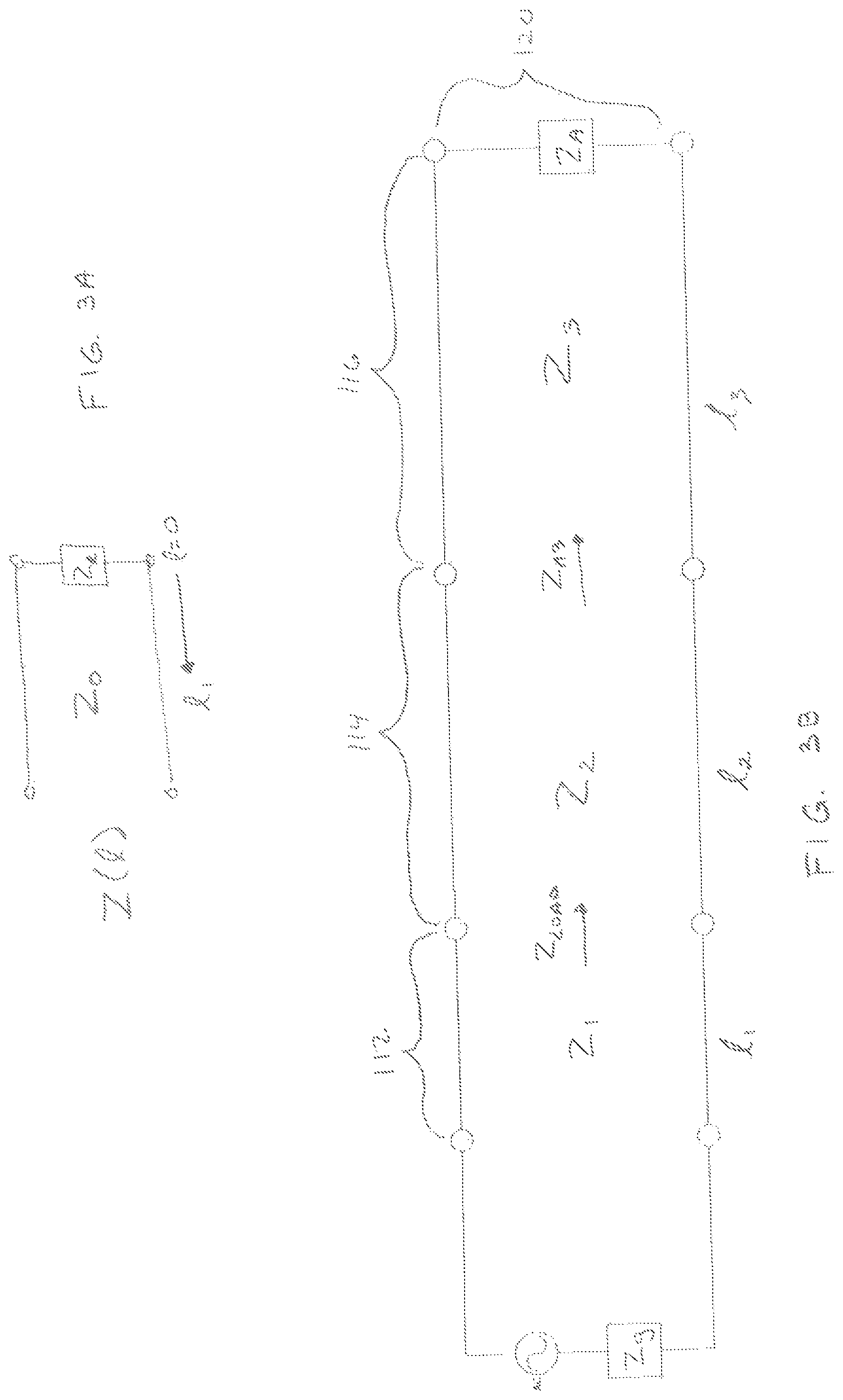
FIG. 3A is a schematic representation of a basic transmission line;
FIG. 3B is a transmission line network representation of the microwave applicator of FIG. 2;
FIG. 4A is a schematic representation of a first transmission line section of the microwave applicator of FIG. 2;
FIG. 4B is a schematic representation of a second transmission line section of the microwave applicator of FIG. 2;
FIG. 4C is a schematic representation of a third transmission line section of the microwave applicator of FIG. 2;
FIG. 4D is a schematic representation of a distal radiating section of the microwave applicator of FIG. 2; and
FIG. 5 is a combined schematic representation of FIGS. 4A-4D.
DETAILED DESCRIPTION
The present disclosure is generally directed to microwave ablation device capable of optimizing the power transfer from a generator to an antenna load while miniaturizing the cross section diameter of the microwave applicator. This is accomplished in part by matching the impedance of the generator and a first transmission line segment to the impedance looking into the network including second and third transmission line segments that terminate at the antenna.
According to the present disclosure, the diameter of the antenna geometry may be reduced to be less than or equal to the diameter of the coaxial feed-line. The miniaturization of the antenna geometry provides at least the following advantages: (1) it reduces the overall radial size of the microwave applicator without significantly compromising ablation performance or device strength; (2) it enables use of a larger coaxial cable feed-line, which reduces energy loss in the coaxial cable feed-line and thus increases energy delivery to the radiator; (3) it provides additional space within the microwave applicator without increasing overall radial size for various structures and features of the microwave applicator, such as the fluid channels, strengthening members, and centering features or sensors; and (4) it enables various manufacturing techniques, such as sliding the fully assembled microwave components into a multi-lumen catheter from one end, which would otherwise not be possible because of inconsistent radial dimensions between the microwave coaxial cable and the antenna.
With respect to endobronchial ablation, the miniaturization of the microwave applicator enables the technical feasibility (e.g., required tissue effect and appropriateness of the cooling) of a saline or water dielectric buffered and electrically choked (via the balun) microwave radiator at a 2.8 mm bronchoscope channel size. This further improves the tissue effect and cooling performance of the same application sized up to a 3.2 mm bronchoscope channel size device. Other intravascular, percutaneous, surgical, and laparoscopic applications where catheter size (French sizing) is of clinical significance are envisioned to benefit similarly. This may also provide space within the microwave applicator assemblies for thermocouple temperature sensors, which are described in U.S. application Ser. Nos. 13/836,519 and 13/924,277, the disclosure of each of which are incorporated by reference herein. Additionally, by maintaining a line-to-line dimension between the diameter of the feed-line coaxial segment and the diameter of the antenna geometry (including a balun), the microwave applicator assembly may be slid into a closed out (tipped) lumen from the proximal end, thus simplifying the manufacturing process. The manufacturing methods of the present disclosure may be used in the miniaturization and strengthening of ablation needles and catheters.
Embodiments of the microwave ablation systems and components are described with reference to the accompanying drawings. Like reference numerals may refer to similar or identical elements throughout the description of the figures. As shown in the drawings and as used in this description, the term "proximal" refers to that portion of the apparatus, or component of the apparatus, closer to the user and the term "distal" refers to that portion of the apparatus, or a component of the apparatus, farther from the user.
This description may use the phrases "in an embodiment," "in embodiments," "in some embodiments," or "in other embodiments," which may each refer to one or more of the same or different embodiments in accordance with the present disclosure.
As it is used in this description, "microwave" generally refers to electromagnetic waves in the frequency range of 300 megahertz (MHz) (3.times.10.sup.8 cycles/second) to 300 gigahertz (GHz) (3.times.10.sup.11 cycles/second). As it is used in this description, "ablation procedure" generally refers to any ablation procedure, such as, for example, microwave ablation, radiofrequency (RF) ablation, or microwave or RF ablation-assisted resection. As it is used in this description, "transmission line" generally refers to any transmission medium that can be used for the propagation of signals from one point to another. As it is used in this description, "fluid" generally refers to a liquid, a gas, or both.
FIG. 1 is a block diagram of a microwave tissue treatment system 10 in accordance with aspects of the present disclosure. The microwave tissue treatment system 10 includes a microwave tissue treatment device 20 having a microwave applicator or antenna assembly 100 connected to a microwave generator 40 through a feedline 60. The microwave tissue treatment device 20 may include one or more pumps 80, e.g., a peristaltic pump or the like, for circulating a cooling or heat dissipative fluid through the microwave applicator or antenna assembly 100 via an inflow fluid conduit 182 and an outflow fluid conduit 184 of a cooling system 180. The mechanical functionality of the pump in driving fluid through the system may be substituted by driving the fluid with pressurized and regulated reservoirs.
The feedline 60 may range in length from about 7 feet to about 10 feet, but may be either substantially longer or shorter if required in a particular application. The feedline 60 transfers microwave energy to microwave tissue treatment device 20. The feedline 60 includes a coaxial cable having an inner conductor, an outer conductor, and a dielectric interposed between the inner and outer conductors. The dielectric electrically separates and/or isolates the inner conductor from the outer conductor. The feedline 60 may further include any sleeve, tube, jacket, or the like formed of any conductive or non-conductive material. The feedline 60 may be separable from, and connectable to, the antenna assembly 100 or the microwave tissue treatment device 20.
The inner and outer conductors are each formed, at least in part, of a conductive material or metal, such as stainless steel, copper, or gold. In certain embodiments, the inner and outer conductors of feedline 60 may include a conductive or non-conductive substrate that is plated or coated with a suitable conductive material. The dielectric may be formed of a material having a dielectric value and tangential loss constant of sufficient value to electrically separate and/or isolate the respective inner and outer conductors from one another, including but not being limited to, expanded foam polytetrafluoroethylene (PTFE), polymide, silicon dioxide, or fluoropolymer. The dielectric may be formed of any non-conductive material capable of maintaining the desired impedance value and electrical configuration between the respective inner and outer conductors. In addition, the dielectric may be formed from a combination of dielectric materials.
The antenna assembly 100 of the microwave tissue treatment system 10 includes a first transmission line segment 112, a second transmission line segment 114, a third transmission line segment 116 on which a choke or coaxial balun 118 is disposed, a distal radiating section 120, and a dielectric buffering and cooling structure 122.
The proximal portion of the antenna assembly 100 may include a connecting hub 140. The connecting hub 140 defines a conduit configured and dimensioned to receive a distal end of the feedline 60, additional conduits configured and dimensioned to receive the inflow conduit 182 and the outflow conduit 184 of the cooling system 180, and one or more apertures formed in an internal surface of the connecting hub 140 that are configured and dimensioned to receive the inflow conduit 182 and the outflow conduit 184, respectively. Connecting hub 140 may be formed of any suitable material including, but not limited to, polymeric materials. Although not explicitly shown, the hub may also include conduits configured and dimensioned to receive sensors, including but not limited to thermocouples, electromagnetic navigation coils, or impedance monitoring electrodes, and may house one or more components of a radiometer used to sense the effects of ablation on the emissions of tissue.
As described above, the antenna assembly 100 of the present disclosure minimizes the radial dimension of a microwave applicator 200. Specifically the radial dimensions of the metallic structure of the microwave applicator 200 are optimized to match the impedance of the generator and first transmission line section 112 with the second and third transmission line sections 114 and 116, respectively, as will be described below with reference to FIGS. 2-5.
FIG. 2 shows the microwave applicator 200 inserted into the dielectric buffering and cooling structure 122. The first transmission line segment 112 (FIG. 1) may be constructed of a coaxial cable of any variety, including a rigid, semi-rigid, or flexible coaxial cable. The impedance of the waveguide formed by the coaxial cable may be 50 ohms, but may range from 20 ohms to 150 ohms. An inner conductor 212 of the first transmission line section segment 112 is surrounded by a dielectric insulator 214, which, in turn, is partially or fully covered by an outer conductor 216 (also referred to as a shield).
The inner conductor 212 may be a silver-plated solid copper wire. The dielectric insulator 214 may be a dielectric tape, an extruded polytetrafluoroethylene (PTFE) dielectric insulator, wrapped PTFE, foamed PTFE, or perfluoroalkoxy (PFA). The outer conductor 216 may be a silver-plated copper wire braid constructed from either flat or round braid wire. A jacket (not shown) for environmental and mechanical robustness may be applied onto or melted into the braided shield. The jacket may be a heat shrink material, such as polyethylene terephthalate (PET) or fluorinated ethylene propylene (FEP), or an extruded thermoplastic. The first transmission line segment 112 has an outer radial dimension d.sub.1 (See FIG. 5).
The second transmission line segment 114 may include an inner conductor 222 that is the same as the inner conductor 212 of the coaxial feed-line segment 112. Thus, the inner conductor 222 may be unchanged and seamless between the first transmission line segment 112 and the second transmission line segment 114 to simplify manufacture of the microwave applicator and improve electrical performance. In other words, the inner conductor 222 may be an extension of the inner conductor 212. In embodiments, the radial dimension of the inner conductor 222 may be reduced. The difference between the first transmission line segment 112 and the second transmission line segment 114 is that the outer radial dimension of the second transmission line segment segment 114 d.sub.2 is reduced by employing a dielectric insulator 224 having a reduced diameter as compared to dielectric insulator 214 of the first transmission line segment.
The length of the second transmission line segment 114 may be optimized for electrical performance at one quarter of the wavelength of the frequency of operation. The length of the second transmission line segment 114 may be scaled by the dielectric constant of the second transmission line segment's dielectric insulator 224. For example, the length of the second transmission line segment 114 may be 2.1 cm for an operation frequency of 2450 MHz. In other embodiments, the length of the second transmission line segment 114 may deviate from a quarter wavelength. For example, the length of the second transmission line segment 114 may be 5.6 cm for an operation frequency of 915 MHz and 0.9 cm for 5800 MHz. In yet other embodiments, the second transmission line segment 114 may be stepped down using a variety of approaches including a taper step down, a multiple segment step down, or an exponential tapering.
The second transmission line segment 114 may be constructed from the same materials as the first transmission line segment 112, or the second transmission line segment 114 may use a different combination of materials than the first transmission line segment 112. The dielectric insulator 224 may be a foamed PTFE, such as low-density PTFE (LDPTFE) or microporous PTFE, tape-wrapped PTFE, tape-wrapped and sintered PTFE, or PFA. The outer conductor 226 may be a silver-plated copper flat wire braid, a solid-drawn copper tube, a conductive ink-coated PET heat shrink (e.g., silver ink-coated PET heat shrink), or a silver-plated copper-clad steel braid.
The third transmission line segment 116 may include an inner conductor 232 that is unchanged and seamless with the inner conductor 222 of the second transmission line segment 114 and the inner conductor 212 of the first transmission line segment 112, which would simplify manufacture of the third transmission line segment 116 and would improve electrical performance. If the inner conductor 232 of the third transmission line segment 116 were to change with the third transmission line segment 116, its radial dimension may be reduced. A difference between the third transmission line segment 116 and the second transmission line segment 114 is that the outer radial dimension of the third transmission line segment 116 d.sub.3 is reduced again by employing a dielectric insulator 234 having a reduced diameter as compared to dielectric insulator 214 of the first transmission line segment 112 and dielectric insulator 224 of the second transmission line segment 114.
The third transmission line segment 116 may be constructed from the same materials as or different materials from the first transmission line segment 112 and/or the second transmission line segment 114. The dielectric insulator 234 of the radiator base segment 116 may be a low-density PTFE (e.g., a foamed PTFE), a tape-wrapped PTFE, a tape-wrapped and sintered PTFE, or a PFA. The outer conductor 236 may be a silver-plated copper flat-wire braid, a solid-drawn copper tube, a silver ink-coated PET heat shrink, or a silver-plated copper-clad steel braid.
The coaxial balun 118 is assembled on top of the third transmission line segment 116 as shown in FIG. 2. The coaxial balun 118 is composed of a balun dielectric insulator 118a and a balun outer conductor 118b. The balun dielectric insulator 118a may extend beyond the distal end of the balun outer conductor 118b.
The overall outer diameter of the coaxial balun 118 d.sub.A may be set equal to or less than the overall outer diameter of the first transmission line segment 112, such that the largest overall radial dimension of the device is not increased by the coaxial balun 118. The coaxial balun 118 may be constructed from the same materials as the first transmission line segment 112, or may vary from the specific materials of the first transmission line segment 112.
The third transmission line segment 116 includes a feed gap 237 formed by the exposing of the dielectric insulator 234 and the removal of the distal most portion of the outer conductor 236. The portion of the outer conductor 236 extending beyond the distal end of the balun outer conductor 118b, and extending to the feed gap 237 forms a proximal radiating section 238. Distal of the feed gap 237, the distal radiating section 120 includes an elongated conductor 242 which is soldered, crimped, or welded onto the distal end of the inner conductor 232 of the third transmission line segment 116 and may abut against the distal end of the feed gap 237 formed from the dielectric insulator 234. The feed gap 237 may be considered as a portion of the length of either the distal radiating section (120) or proximal radiating section (238). In combination the proximal and distal radiating sections 238 and 120 form radiator 250. The shape of the elongated conductor 242 may be a cylinder. Alternatively, the distal radiating section 120 may be composed of several cylinders of varying diameter, such as a barbell or pin with a widened base. Additional heat-sinking features, such as burs and fins, may be added to the elongated conductor 242 to increase the radiating effectiveness of the microwave applicator 200. These features, such as the barbell mentioned above, may also help to center the radiator within the dielectric buffering and cooling structure 122, further controlling the shape of the electromagnetic field produced, as concentricity of the radiator within the structure 122 is a factor in field shape.
The radiator 250 may be constructed from the same materials as or different materials from the first transmission line segment 112, the second transmission line segment 114, and/or the third transmission line segment 116.
The dielectric buffering and cooling structure 122 includes a mechanical support for the device, circulated cooling fluid, such as gas or liquid, and chambers to enable the circulation of the fluid, such as concentric inflow and outflow tubes 202 and 203 forming fluid paths 208 and 206, respectively. The dielectric buffering of the antenna from the surrounding tissue environment is provided by the circulated liquid extending over the length of the radiating section. Alternatively, the cooling lumens and fluids may terminate proximal to the distal radiating section 120 and high dielectric solid material may be disposed distally over the radiating section 120 of the microwave applicator to dielectrically buffer the antenna and provide mechanical stiffness and enhanced tissue cutting for advancing the radiating section into and/or through tissue.
The dielectric buffering and cooling structure 122 may be composed of various thermoplastics and may be manufactured according to a multi-lumen extrusion approach. The dielectric buffering and cooling structure 122 may include an outflow tube 203 composed of fiber glass and an inflow tube 202 composed of polyimide or PET extrusion and may be manufactured according to a concentric approach, in which materials are layered upon each other. The inflow tube 202 and the outflow tube 203 may alternatively be composed of a Kevlar braid thermoplastic composite. The cooling fluid may be water, saline, or any common water-based liquid. The high dielectric solid material may be a ceramic material, such as YTZP.
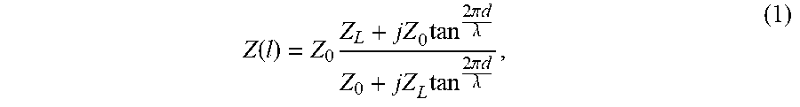
In order to maximize the power transfer from the generator to the antenna assembly/tissue, the impedance Z.sub.LOAD, which is the impedance at the junction of the first transmission line segment 112 and the second transmission line segment 114, should be substantially equal to the generator impedance Z.sub.G. The design of the microwave applicator 200 capable of achieving the maximum power transfer will be discussed below with reference to the schematic representations shown in FIGS. 3A through 5. FIG. 3A is a schematic representation of a basic transmission line. In the transmission line shown in FIG. 3A, the impedance Z(l) of the transmission line is calculated as follows:
.function..times..times..times..pi..times..times..lamda..times..times..pi- ..times..times..lamda. ##EQU00001## where Z.sub.0 is the impedance of the transmission line, l is the length of the line, and Z.sub.L is the impedance of the load terminating the line. In situations where the length of the line l is equal to a quarter wavelength, the impedance of the transmission line is calculated as follows:
.function..lamda. ##EQU00002##
Impedance Z.sub.A of the distal radiating section 120 is optimized for spherical ablation in tissue and the first transmission line segment 112 is designed to have an impedance Z.sub.1 that is equal to the impedance Z.sub.G of the generator.
Starting with the junction between the third transmission line segment 116 and the distal radiating section 120, the impedance Z.sub.A3 is calculated using equation (1) as follows:
.times..times..times..times..times..pi..times..times..lamda..times..times- ..pi..times..times..lamda. ##EQU00003## Using equations (1) and (3) above, the impedance Z.sub.LOAD at the junction of the first transmission line segment 112 and the second transmission line segment 114 is calculated as follows:
.times..times..times..times..times..pi..times..times..lamda..times..times- ..times..times..pi..times..times..lamda. ##EQU00004##
By setting the length l.sub.2 of the second transmission line segment 114 to a quarter wavelength, the impedance Z.sub.LOAD is calculated using equation (2) as follows:
.times..times..times..times..times..times..times..times..times..lamda..ti- mes..times. ##EQU00005## Then equation (3) is substituted into equation (5) and the impedance Z.sub.LOAD is calculated as follows:
.times..times..times..times..pi..times..times..lamda..times..times..times- ..pi..times..times..lamda. ##EQU00006## The impedance of the second transmission line section 114 is calculated by solving equation (6) for Z.sub.2 as follows:
.times..times..times..times..times..pi..times..times..lamda..times..times- ..times..pi..times..times..lamda. ##EQU00007## By setting Z.sub.load equal to the impedance of the first transmission line segment 112, i.e. the impedance match condition, and grouping terms, equation (7) can be simplified as follows:
.times..times..times..times..lamda..times..times..times..times..times..ti- mes..lamda..times. ##EQU00008##
Thus, in order to optimize the match between the generator and the microwave applicator the length l.sub.3 of the third transmission line segment is adjusted where the length l.sub.3 is greater than a quarter wavelength of the microwave energy due to the presence of the balun 116 and an antenna proximal arm 239 (FIG. 2). The impedance Z.sub.2 of the second transmission line segment 114 is selected to range between the impedance Z.sub.1 of the first transmission line segment 112 and the impedance Z.sub.3 of the third transmission line segment 116. The impedances of the first, second, and third transmission line segments 112, 114 and 116 are based on the processing techniques and the materials used to construct the segments. Adjusting the length of l.sub.3 matches the impedance of the network looking toward the antenna from the junction between the first (112) and second (114) transmission line segments to the impedance for the first transmission line segment (112) and therefore the generator impedance.
Although embodiments have been described in detail with reference to the accompanying drawings for the purpose of illustration and description, it is to be understood that the inventive processes and apparatus are not to be construed as limited thereby. It will be apparent to those of ordinary skill in the art that various modifications to the foregoing embodiments may be made without departing from the scope of the disclosure.
* * * * *
References
D00000
D00001
D00002
D00003
D00004
D00005
D00006
M00001
M00002
M00003
M00004
M00005
M00006

M00007

M00008

XML
uspto.report is an independent third-party trademark research tool that is not affiliated, endorsed, or sponsored by the United States Patent and Trademark Office (USPTO) or any other governmental organization. The information provided by uspto.report is based on publicly available data at the time of writing and is intended for informational purposes only.
While we strive to provide accurate and up-to-date information, we do not guarantee the accuracy, completeness, reliability, or suitability of the information displayed on this site. The use of this site is at your own risk. Any reliance you place on such information is therefore strictly at your own risk.
All official trademark data, including owner information, should be verified by visiting the official USPTO website at www.uspto.gov. This site is not intended to replace professional legal advice and should not be used as a substitute for consulting with a legal professional who is knowledgeable about trademark law.