Medical devices with detachable pivotable jaws
Surti , et al. October 27, 2
U.S. patent number 10,813,650 [Application Number 15/977,066] was granted by the patent office on 2020-10-27 for medical devices with detachable pivotable jaws. This patent grant is currently assigned to Cook Medical Technologies LLC. The grantee listed for this patent is Cook Medical Technologies LLC. Invention is credited to Michelle D. Martinez, Vihar C. Surti.


| United States Patent | 10,813,650 |
| Surti , et al. | October 27, 2020 |
Medical devices with detachable pivotable jaws
Abstract
Medical systems, devices and methods are provided for engaging tissue, e.g. for clipping tissue, closing a perforation or performing hemostasis. Generally, the medical system including a housing, first and second jaws rotatable relative to the housing, a driver, and an elongate drive wire. The elongate drive wire may be disconnected from the driver, first and second jaws, and the housing, which are left in vivo engaged with the tissue.
| Inventors: | Surti; Vihar C. (Winston-Salem, NC), Martinez; Michelle D. (Winston-Salem, NC) | ||||||||||
|---|---|---|---|---|---|---|---|---|---|---|---|
| Applicant: |
|
||||||||||
| Assignee: | Cook Medical Technologies LLC
(Bloomington, IN) |
||||||||||
| Family ID: | 1000005139585 | ||||||||||
| Appl. No.: | 15/977,066 | ||||||||||
| Filed: | May 11, 2018 |
Prior Publication Data
| Document Identifier | Publication Date | |
|---|---|---|
| US 20180256169 A1 | Sep 13, 2018 | |
Related U.S. Patent Documents
| Application Number | Filing Date | Patent Number | Issue Date | ||
|---|---|---|---|---|---|
| 14753464 | Jun 29, 2015 | 9987018 | |||
| 14285009 | Jun 28, 2016 | 9375219 | |||
| 12971873 | Jul 8, 2014 | 8771293 | |||
| 61289297 | Dec 22, 2009 | ||||
| Current U.S. Class: | 1/1 |
| Current CPC Class: | A61B 17/122 (20130101); A61B 17/1285 (20130101); A61B 17/08 (20130101); A61B 17/10 (20130101); A61B 2017/00473 (20130101); A61B 17/29 (20130101); A61B 2017/2936 (20130101); A61B 2017/2931 (20130101); A61B 2017/2944 (20130101); A61B 2017/12004 (20130101); A61B 2017/2902 (20130101); A61B 2017/2943 (20130101) |
| Current International Class: | A61B 17/128 (20060101); A61B 17/122 (20060101); A61B 17/08 (20060101); A61B 17/10 (20060101); A61B 17/29 (20060101); A61B 17/00 (20060101); A61B 17/12 (20060101) |
References Cited [Referenced By]
U.S. Patent Documents
| 720385 | February 1903 | Storle |
| 2384697 | September 1945 | Riccardi |
| 2598901 | June 1952 | Garland |
| 2614445 | October 1952 | Riordan |
| 3363628 | January 1968 | Wood |
| 3463156 | August 1969 | McDermott |
| 3481641 | December 1969 | Berger et al. |
| 3581745 | June 1971 | Eller |
| 3867944 | February 1975 | Samuels |
| 3924303 | December 1975 | Elliott |
| 3932918 | January 1976 | Paskert |
| 3958576 | May 1976 | Komiya |
| 4453756 | June 1984 | Haag |
| 4467802 | August 1984 | Maslanka |
| 4512345 | April 1985 | Green |
| 4519392 | May 1985 | Lingua |
| 4569131 | February 1986 | Falk et al. |
| 4733664 | March 1988 | Kirsch et al. |
| 4763668 | August 1988 | Macek et al. |
| 4765335 | August 1988 | Schmidt et al. |
| 4805618 | February 1989 | Ueda et al. |
| 4822348 | April 1989 | Casey |
| 4950273 | August 1990 | Briggs |
| 4955897 | September 1990 | Ship |
| 4990152 | February 1991 | Yoon |
| 5029355 | July 1991 | Thai |
| 5049153 | September 1991 | Nakao et al. |
| 5100418 | March 1992 | Yoon et al. |
| 5100430 | March 1992 | Avellanet et al. |
| 5133727 | July 1992 | Bales et al. |
| 5141519 | August 1992 | Smith et al. |
| 5147357 | September 1992 | Rose et al. |
| 5152778 | October 1992 | Bales, Jr. et al. |
| 5156609 | October 1992 | Nakao et al. |
| 5174276 | December 1992 | Crockard |
| 5192298 | March 1993 | Smith et al. |
| 5201743 | April 1993 | Haber et al. |
| 5209747 | May 1993 | Knoepfler |
| 5211655 | May 1993 | Hasson |
| 5222961 | June 1993 | Nakao et al. |
| 5242456 | September 1993 | Nash et al. |
| 5275608 | January 1994 | Forman et al. |
| 5275613 | January 1994 | Haber et al. |
| 5275615 | January 1994 | Rose |
| 5282806 | February 1994 | Haber et al. |
| 5304183 | April 1994 | Gourlay et al. |
| 5306283 | April 1994 | Conners |
| 5318589 | June 1994 | Lichtman |
| 5368606 | November 1994 | Marlow et al. |
| 5407243 | April 1995 | Riemann |
| 5423857 | June 1995 | Rosenman et al. |
| 5471992 | December 1995 | Banik et al. |
| 5474569 | December 1995 | Zinreich et al. |
| 5499998 | March 1996 | Meade |
| 5501693 | March 1996 | Gravener |
| 5507758 | April 1996 | Thomason et al. |
| 5509923 | April 1996 | Middleman et al. |
| 5520701 | May 1996 | Lerch |
| 5542432 | August 1996 | Slater |
| 5569274 | October 1996 | Rapacki et al. |
| 5571137 | November 1996 | Marlow et al. |
| 5584855 | December 1996 | Onik |
| 5618303 | April 1997 | Marlow et al. |
| 5620452 | April 1997 | Yoon |
| 5626607 | May 1997 | Malecki et al. |
| 5632764 | May 1997 | Beideman et al. |
| 5634932 | June 1997 | Schmidt |
| 5665100 | September 1997 | Yoon |
| 5702407 | December 1997 | Kaji |
| 5728121 | February 1998 | Bimbo et al. |
| 5766184 | June 1998 | Matsuno et al. |
| 5766189 | June 1998 | Matsuno |
| 5782748 | July 1998 | Palmer et al. |
| 5792165 | August 1998 | Kilieman et al. |
| 5797923 | August 1998 | Aiyar et al. |
| 5797939 | August 1998 | Yoon |
| 5797941 | August 1998 | Schulze et al. |
| 5797958 | August 1998 | Yoon |
| 5846255 | December 1998 | Casey |
| 5893863 | April 1999 | Yoon |
| 5893875 | April 1999 | O'Connor et al. |
| 5893878 | April 1999 | Pierce |
| 5902310 | May 1999 | Foerster et al. |
| 5922002 | July 1999 | Yoon |
| 5964779 | October 1999 | Mayenberger et al. |
| 5984939 | November 1999 | Yoon |
| 6007552 | December 1999 | Fogarty et al. |
| 6010523 | January 2000 | Sabin et al. |
| 6059719 | May 2000 | Yamamoto et al. |
| 6106041 | August 2000 | Eckhardt |
| 6139563 | October 2000 | Cosgrove, III et al. |
| 6258105 | July 2001 | Hart et al. |
| 6358197 | March 2002 | Silverman et al. |
| 6386496 | May 2002 | Lai et al. |
| 6464710 | October 2002 | Foster |
| 6613059 | September 2003 | Schaller et al. |
| 6814742 | November 2004 | Kimura et al. |
| 6923818 | August 2005 | Muramatsu et al. |
| 6991634 | January 2006 | Sugiyama et al. |
| 7011667 | March 2006 | Kobayashi et al. |
| 7041118 | May 2006 | Muramatsu et al. |
| 7081121 | July 2006 | Muramatsu et al. |
| 7175649 | February 2007 | Nakao |
| 7207997 | April 2007 | Shipp et al. |
| 7223271 | May 2007 | Muramatsu et al. |
| 7223272 | May 2007 | Francese et al. |
| 7326221 | February 2008 | Sakamoto |
| 7452327 | November 2008 | Durgin et al. |
| 7488334 | February 2009 | Jugenheimer et al. |
| 7494461 | February 2009 | Wells et al. |
| 7601159 | October 2009 | Ewers et al. |
| 7722628 | May 2010 | Stokes et al. |
| 7727247 | June 2010 | Kimura et al. |
| 7736372 | June 2010 | Reydel et al. |
| 7736374 | June 2010 | Vaughan et al. |
| 7740639 | June 2010 | Hummel et al. |
| 7744613 | June 2010 | Ewers et al. |
| 7766810 | August 2010 | Ohdaira |
| 7776057 | August 2010 | Laufer et al. |
| 7815652 | October 2010 | Messerly et al. |
| 7896895 | March 2011 | Boudreaux et al. |
| 8062311 | November 2011 | Litscher et al. |
| 8083668 | December 2011 | Durgin et al. |
| 8088061 | January 2012 | Wells et al. |
| 8172859 | May 2012 | Matsuno et al. |
| 8317820 | November 2012 | Surti |
| 8348964 | January 2013 | Kimura et al. |
| 8545519 | October 2013 | Aguirre et al. |
| 8709027 | April 2014 | Adams et al. |
| 8771293 | July 2014 | Surti et al. |
| 8858588 | October 2014 | Sigmon, Jr. et al. |
| 8939997 | January 2015 | Martinez et al. |
| 8979891 | March 2015 | McLawhorn et al. |
| 2001/0034536 | October 2001 | Looper et al. |
| 2002/0045909 | April 2002 | Kimura et al. |
| 2002/0151916 | October 2002 | Muramatsu et al. |
| 2002/0173805 | November 2002 | Matsuno et al. |
| 2002/0177861 | November 2002 | Sugiyama et al. |
| 2003/0069592 | April 2003 | Adams et al. |
| 2003/0097146 | May 2003 | Montalvo et al. |
| 2003/0191494 | October 2003 | Gray et al. |
| 2004/0044363 | March 2004 | Fowler |
| 2005/0033312 | February 2005 | Suzuki |
| 2005/0059985 | March 2005 | Kimura |
| 2005/0101991 | May 2005 | Ahlberg et al. |
| 2005/0234296 | October 2005 | Saadat et al. |
| 2005/0251183 | November 2005 | Buckman et al. |
| 2005/0272977 | December 2005 | Saadat et al. |
| 2006/0084886 | April 2006 | Reydel |
| 2006/0155308 | July 2006 | Griego |
| 2006/0161182 | July 2006 | Vandenbroek |
| 2006/0258905 | November 2006 | Kaji et al. |
| 2006/0259045 | November 2006 | Damarati |
| 2007/0073185 | March 2007 | Nakao |
| 2007/0135678 | June 2007 | Suzuki |
| 2007/0239162 | October 2007 | Bhatnagar et al. |
| 2007/0250113 | October 2007 | Hegeman et al. |
| 2007/0282355 | December 2007 | Brown et al. |
| 2007/0287993 | December 2007 | Hinman et al. |
| 2008/0004656 | January 2008 | Livneh |
| 2008/0147113 | June 2008 | Nobis et al. |
| 2008/0171907 | July 2008 | Long et al. |
| 2008/0228199 | September 2008 | Cropper et al. |
| 2008/0228202 | September 2008 | Cropper et al. |
| 2008/0234703 | September 2008 | Cropper et al. |
| 2008/0234705 | September 2008 | Cropper et al. |
| 2008/0255427 | October 2008 | Satake et al. |
| 2008/0262539 | October 2008 | Ewers et al. |
| 2008/0269557 | October 2008 | Marescaux et al. |
| 2008/0269566 | October 2008 | Measamer |
| 2008/0275441 | November 2008 | Aue |
| 2008/0287963 | November 2008 | Rogers et al. |
| 2008/0294178 | November 2008 | Kortenbach et al. |
| 2008/0300461 | December 2008 | Shaw et al. |
| 2008/0300624 | December 2008 | Schwemberger et al. |
| 2009/0005638 | January 2009 | Zwolinski |
| 2009/0018602 | January 2009 | Mitelberg et al. |
| 2009/0043316 | February 2009 | Durgin et al. |
| 2009/0062792 | March 2009 | Vakharia et al. |
| 2009/0138006 | May 2009 | Bales et al. |
| 2009/0138028 | May 2009 | Wells et al. |
| 2009/0143794 | June 2009 | Conlon et al. |
| 2009/0163934 | June 2009 | Raschdorf, Jr. et al. |
| 2009/0192344 | July 2009 | Bakos et al. |
| 2009/0221915 | September 2009 | Voegele et al. |
| 2009/0299385 | December 2009 | Stefanchik et al. |
| 2009/0306683 | December 2009 | Zwolinski et al. |
| 2009/0306686 | December 2009 | Ohdaira |
| 2009/0326518 | December 2009 | Rabin |
| 2009/0326578 | December 2009 | Ewers et al. |
| 2010/0010512 | February 2010 | Taylor et al. |
| 2010/0042115 | February 2010 | Saadar et al. |
| 2010/0057078 | March 2010 | Arts et al. |
| 2010/0057085 | March 2010 | Holcomb et al. |
| 2010/0130817 | May 2010 | Conlon |
| 2010/0168787 | July 2010 | Surti |
| 2010/0179540 | July 2010 | Marczyk et al. |
| 2010/0198149 | August 2010 | Fox |
| 2010/0198248 | August 2010 | Vakharia |
| 2010/0211086 | August 2010 | Ewers et al. |
| 2010/0217151 | August 2010 | Gostout et al. |
| 2010/0217292 | August 2010 | Kimura et al. |
| 2010/0217293 | August 2010 | Kimura et al. |
| 2010/0217294 | August 2010 | Kumura et al. |
| 2010/0249498 | September 2010 | Wingardner et al. |
| 2010/0249700 | September 2010 | Spivey |
| 2010/0249808 | September 2010 | Harada et al. |
| 2011/0152888 | June 2011 | Ho et al. |
| 2012/0016391 | January 2012 | Aguirre et al. |
| 2012/0089158 | April 2012 | Martenez et al. |
| 2012/0089176 | April 2012 | Sigmon, Jr. et al. |
| 2012/0109160 | May 2012 | Martenez et al. |
| 2012/0165863 | June 2012 | McLawhorn |
| 2012/0232338 | September 2012 | Livneh |
| 2012/0249498 | September 2012 | Wingardner et al. |
| 2012/0051200 | November 2012 | Matenez et al. |
| 4404766 | Aug 1995 | DE | |||
| 19534320 | Feb 1997 | DE | |||
| 19750878 | May 1999 | DE | |||
| 19906360 | Aug 2000 | DE | |||
| 102006003548 | Aug 2007 | DE | |||
| 0246087 | Nov 1987 | EP | |||
| 0541930 | May 1993 | EP | |||
| 0738501 | Oct 1996 | EP | |||
| 790997 | Nov 1935 | FR | |||
| 2476461 | Jun 2011 | GB | |||
| 57-156752 | Sep 1982 | JP | |||
| 60-103946 | Jun 1985 | JP | |||
| 63-6016 | Feb 1988 | JP | |||
| 63-267345 | Nov 1988 | JP | |||
| 63-288147 | Nov 1988 | JP | |||
| 2-6011 | Jan 1990 | JP | |||
| 2007950 | Jan 1990 | JP | |||
| 4-26091 | Mar 1992 | JP | |||
| 4102450 | Apr 1992 | JP | |||
| 5-212043 | Aug 1993 | JP | |||
| 5208020 | Aug 1993 | JP | |||
| 5212042 | Aug 1993 | JP | |||
| 6237939 | Aug 1994 | JP | |||
| 6254101 | Sep 1994 | JP | |||
| 8019548 | Jan 1996 | JP | |||
| 8126648 | May 1996 | JP | |||
| 8280701 | Oct 1996 | JP | |||
| 8308847 | Nov 1996 | JP | |||
| 9038093 | Feb 1997 | JP | |||
| 9289989 | Nov 1997 | JP | |||
| 2000-33090 | Feb 2000 | JP | |||
| 2000-335631 | Dec 2000 | JP | |||
| 2001-520069 | Oct 2001 | JP | |||
| 2002-224124 | Aug 2002 | JP | |||
| 2002-301082 | Oct 2002 | JP | |||
| 2002-360585 | Dec 2002 | JP | |||
| WO 9614020 | May 1996 | WO | |||
| WO 99/20183 | Apr 1999 | WO | |||
| WO 2004/017839 | Apr 2004 | WO | |||
| WO 2008/005433 | Jan 2008 | WO | |||
| WO 2010/078163 | Jul 2010 | WO | |||
| WO 2011/087723 | Jul 2011 | WO | |||
| WO 2012/051188 | Apr 2012 | WO | |||
| WO 2012/051191 | Apr 2012 | WO | |||
| WO 2012/051200 | Apr 2012 | WO | |||
| WO 2012/083041 | Jun 2012 | WO | |||
Other References
|
Extended European Search Report, European Application No. 18194861.3, dated Mar. 4, 2019, 9 pgs. cited by applicant . International Search Report/Written Opinion for PCT/US2009/069270 (dated May 17, 2010). cited by applicant . International Search Report/Written Opinion for PCT/US2010/061077 (dated Apr. 1, 2011). cited by applicant . Olympus Endo Therapy brochure on the QuickClip2 Long. cited by applicant . CooperSurgical brochure on the Marlow Nu-Tip Laparoscopic Instruments. cited by applicant . Medwork brochure, Endo Therapy for the Clipmaster 3. cited by applicant . Boston Scientific Catalog on the Resolution Clip Device. cited by applicant . Medicon Instrument Catalog, pp. 440, 441, 443, 451, 585, 686 (1986). cited by applicant . V. Mueller, The Surgical Armamentarium, pp. F176-F177 (1988). cited by applicant . Annex to Form PCT/ISA/206--Communication Relating to the Results of Partial International Search for PCT/US2011/055800 (dated Jun. 28, 2012). cited by applicant . International Search Report and Opinion for PCT/US2011/055780 (dated Jun. 14, 2012). cited by applicant . International Search Report and Opinion for PCT/US2011/055786 (dated Jun. 19, 2012). cited by applicant . International Search Report and Opinion for PCT/US2011/065200 (dated Jun. 13, 2012). cited by applicant . Office Action dated Dec. 24, 2013 U.S. Appl. No. 13/270,784 in related application. cited by applicant . International Search Report and Opinion for PCT/US2011/055800 (dated Sep. 12, 2012). cited by applicant . International Search Report and Opinion for PCT/US2012/046666 (dated Oct. 8, 2012). cited by applicant . Office Action dated Jan. 18, 2012 for U.S. Appl. No. 12/645,004 in related application. cited by applicant . Office Action dated May 29, 2012 for U.S. Appl. No. 12/645,004 in related application. cited by applicant . Office Action dated Dec. 20, 2012 for U.S. Appl. No. 13/186,427 in related application. cited by applicant . Office Action dated May 6, 2013 for U.S. Appl. No. 12/971,873 in related application. cited by applicant . Office Action dated Nov. 6, 2013 for U.S. Appl. No. 12/971,873 in related application. cited by applicant . Office Action dated Mar. 10, 2014 for U.S. Appl. No. 13/270,851 in related application. cited by applicant . Office Action dated Mar. 17, 2014 for U.S. Appl. No. 13/270,834 in related application. cited by applicant . Office Action dated Feb. 26, 2014 for U.S. Appl. No. 13/327,127 in related application. cited by applicant . Product brochure entitled "Hemostatic Grasper" , 2014 Olympus America, Inc., Jul. 1, 2014, pp. 1-3 (https://medical.olympusamerica.com/products/coagrasper). cited by applicant . Product brochure entitled "Titanium Hemostatic Clip", Jorgensen Laboratories, Inc., Loveland, Colorado 80538. cited by applicant. |
Primary Examiner: David; Shaun L
Attorney, Agent or Firm: Brinks Gilson & Lione
Parent Case Text
CROSS-REFERENCE TO RELATED APPLICATIONS
This application is a Continuation of U.S. patent application Ser. No. 14/753,464, filed on Jun. 29, 2015, which is a Continuation of Ser. No. 14/285,009 filed on May 22, 2014, now U.S. Pat. No. 9,375,219, which is a Divisional of U.S. patent application Ser. No. 12/971,873 filed on Dec. 17, 2010, now U.S. Pat. No. 8,771,293, and also claims the benefit of U.S. Provisional Patent Application Ser. No. 61/289,297 filed on Dec. 22, 2009, entitled "MEDICAL DEVICES WITH DETACHABLE PIVOTABLE JAWS", all of the foregoing applications are hereby incorporated herein by reference.
Claims
The invention claimed is:
1. A medical device for engaging tissue, the medical device comprising: a housing defining an internal passageway and a longitudinal axis extending between proximal and distal ends of the housing; a first jaw slidably and pivotally connected to the housing, the first jaw having proximal and distal ends, the first jaw slidably received within the internal passageway for longitudinal movement between an extended position and a retracted position; a second jaw slidably and pivotally connected to the housing, the second jaw having proximal and distal ends, the second jaw slidably received within the internal passageway for longitudinal movement between an extended position and a retracted position; and a driver engaged with the proximal ends of the first and second jaws for movement therewith between their retracted positions and their extended positions, wherein, when the first and second jaws are in their retracted positions, a first distal advancement of the driver moves the first and second jaws distally towards their extended positions without rotation of the first and second jaws, wherein, when the jaws are in their extended positions, a second distal advancement of the driver rotates the first and second jaws relative to the housing, wherein the proximal ends of the first and second jaws maintain their radial position relative to the longitudinal axis during the first and second distal advancements of the driver, and wherein the housing defines first and second guide surfaces, the first and second guide surfaces each having a distal end, the first and second guide surfaces guiding longitudinal movement of the first and second jaws, respectively, and wherein the distal ends of the first and second guide surfaces restrict longitudinal movement of the first and second jaws beyond their extended positions, and wherein, when the first and second jaws are in their extended positions, distal advancement of the driver rotates the first and second jaws relative to the housing.
2. The medical device of claim 1, wherein the housing is sized and structured to limit rotational movement of the first and second jaws during the first distal advancement of the driver.
3. The medical device of claim 1, wherein the housing is sized and structured to permit rotational movement of the first and second jaws during the second distal advancement of the driver.
4. The medical device of claim 1, wherein the housing is sized and structured such that, during a first distal retraction of the driver when the first and second jaws are in their extended positions, the first and second jaws engage the housing and rotate relative to the housing.
5. The medical device of claim 4, wherein the housing is sized and structured such that, during a second distal retraction of the driver subsequent to the first distal retraction, and when the first and second jaws have tissue therebetween, the housing engages the first and second jaws to restrict distal movement of the first and second jaws.
6. The medical device of claim 1, wherein the second distal advancement moves the driver distally relative to the proximal ends of the first and second jaws.
7. The medical device of claim 1, wherein the driver engages the first and second jaws in the retracted position at first and second engagement points on the first and second jaws, and wherein the further distal advancement of the driver moves the driver distally relative to the first and second engagement points.
8. The medical device of claim 1, wherein the driver maintains its radial position relative to the longitudinal axis as the driver moves longitudinally between the retracted position and the extended position of the first and second jaws.
9. The medical device of claim 1, wherein the first and second guide surfaces are formed as channels facing an interior of the housing.
10. The medical device of claim 1, wherein the first and second guide surfaces are slots formed through the housing.
11. The medical device of claim 1, further comprising first and second pins slidably and pivotally connecting the first and second jaws to the housing, wherein the first and second pins slide along the first and second guide surfaces.
12. The medical device of claim 11, wherein the first and second pins abut the distal ends of the first and second guide surfaces in the extended position.
13. The medical device of claim 11, wherein the first and second jaws rotate about the first and second pins, respectively.
14. The medical device of claim 1, wherein the driver is aligned with, and moves longitudinally along, the longitudinal axis as the first and second jaws rotate.
15. The medical device of claim 1, wherein the housing includes a driver guide surface that guides movement of the driver in a longitudinal plane, and wherein the driver guide surface prevents movement of the driver away from the longitudinal plane.
16. The medical device of claim 15, wherein the driver guide surface is defined by two C-shaped channels formed on opposing sides of the housing.
17. The medical device of claim 1, wherein the driver directly engages the proximal ends of the first and second jaws in their retracted positions.
18. The medical device of claim 1, wherein the driver directly engages the proximal ends of the first and second jaws in their extended positions.
Description
BACKGROUND
Conventionally, a clip may be introduced into a body cavity through an endoscope to grasp living tissue of a body cavity for hemostasis, marking, and/or ligating. Such clips are often known as surgical clips, endoscopic clips, hemostasis clips and vascular clips. In addition, clips are now being used in a number of applications related to gastrointestinal bleeding such as peptic ulcers, Mallory-Weiss tears, Dieulafoy's lesions, angiomas, post-papillotomy bleeding, and small varices with active bleeding. Clips have also been attempted for use in closing perforations in the stomach
Gastrointestinal bleeding is a somewhat common and serious condition that is often fatal if left untreated. This problem has prompted the development of a number of endoscopic therapeutic approaches to achieve hemostasis such as the injection of sclerosing agents and contact thermo-coagulation techniques. Although such approaches are often effective, bleeding continues for many patients and corrective surgery therefore becomes necessary. Because surgery is an invasive technique that is associated with a high morbidity rate and many other undesirable side effects, there exists a need for highly effective, less invasive procedures.
Mechanical hemostatic devices such as clips have been used in various parts of the body, including gastrointestinal applications. One of the problems associated with conventional hemostatic devices and clips, however, is that many devices are not strong enough to cause permanent hemostasis. Further, clips have also been attempted for use in closing perforations in the stomach or gastrointestinal structures, but unfortunately traditional clips suffer from difficult placement and the capability to grasp a limited amount of tissue, potentially resulting in incomplete closure.
SUMMARY
The invention may include any of the following aspects in various combinations and may also include any other aspect described below in the written description or in the attached drawings.
In a first aspect, a medical device is provided for engaging tissue, the medical device including a housing, first and second jaws pivotally connected to the housing, and a driver. The housing defines an internal passageway and a longitudinal axis extending between proximal and distal ends of the housing. The housing defines first and second guide surfaces along the internal passageway. The first and second jaws are slidably and pivotally connected to the housing, and each has proximal and distal ends. The first jaw is slidably received within the internal passageway for longitudinal movement along the first guide surface between an extended position and a retracted position. The second jaw is slidably received within the internal passageway for longitudinal movement along the second guide surface between an extended position and a retracted position. The housing is structured to block rotation of the first and second jaws when in their retracted positions, and structured to permit rotation of the first and second jaws when in their extended positions. The driver is engaged with the proximal ends of the first and second jaws, whereby longitudinal movement of the driver moves the first and jaws longitudinally along the first and second guides between their retracted and extended positions. Longitudinal movement of the driver rotates the first and second jaws relative to the housing when the first and second jaws are in their extended positions.
According to more detailed aspects, the proximal ends of the first and second jaws are located adjacent the distal end of the housing when the first and second jaws are in their extended positions. The proximal ends of the first and second jaws are slidably and pivotally attached to the housing. The housing defines a shoulder within the internal passageway, and the driver includes a locking tab positioned to engage the shoulder to limit longitudinal movement of the driver and the first and second jaws. The shoulder moves the locking tab to a position out of engagement with the shoulder when a distally directed longitudinal force on the driver reaches a predetermined force to permit longitudinal movement of the driver and the first and second jaws in a distal direction. Preferably the housing defines a third guide surface that guides longitudinal movement of the driver within the housing. The third guide surface may define the shoulder.
According to still further detailed aspects, the device may also include an elongate drive wire. The elongate drive wire is selectively connected to the driver for longitudinal movement therewith, and the locking tab firmly engages the drive wire when the locking tab is positioned distal to the shoulder, and the locking tab does not firmly engage the drive wire when the locking tab is positioned proximal to the shoulder to permit the drive wire to be disconnected from the driver. The drive wire may have an enlarged distal head, and the driver includes a socket sized to selectively receive the enlarged distal head of the drive wire. The socket faces proximally and is preferably constructed of a resilient material that flexes to adjust the size of the socket. The proximal ends of the first and second jaws include geared teeth, and the driver includes corresponding teeth that mesh with the geared teeth of the jaws. Preferably the proximal ends of the first and second jaws are formed as pinions, and the driver is formed as a rack, wherein longitudinal movement of the driver and rack rotates the pinions and first and second jaws in their extended positions. The driver includes a central spine extending longitudinally and teeth extending laterally from the central spine. Preferably, the driver includes pairs of teeth extending in laterally opposite directions from the spine to form two sets of teeth, one of the two sets of teeth engaged with the pinion of the first jaw, the other of the two sets of teeth engaged with the pinion of the second jaw.
In a second aspect, a medical system is provided for engaging tissue, the medical system including a housing, first and second jaws pivotally connected to the housing, a driver and an elongate drive wire. The housing defines an internal passageway and a longitudinal axis extending between proximal and distal ends of the housing. The housing further defines a driver guide surface along the internal passageway, the driver guide surface including a proximal portion having a proximal width and a distal portion having a distal width. The proximal width is greater than a distal width. The driver is engaged with the proximal ends of the first and second jaws. Longitudinal movement of the driver rotates the first and second jaws relative to the housing. The driver further includes a moveable locking tab. The elongated drive wire selectively connects to the driver for longitudinal movement therewith. The locking tab firmly engages the drive wire when the tab is positioned along the distal portion of the driver guide surface, and the locking tab permits the drive wire to be disconnected from the driver when the locking tab is positioned along the proximal portion of the driver guide surface.
According to more detailed aspects, the elongated drive wire has a distal head and the driver includes a socket sized to receive the distal head. The locking tab is positioned at an entrance to the socket and moves to vary the size of the entrance. The driver includes two locking tabs on opposing sides of the socket, and the driver guide surface includes two surfaces on opposing sides of the housing corresponding to the two locking tabs. The medical system may further include a tubular connector defining a lumen sized to slidably receive a connection block. The connection block is structured to frictionally engage a proximal end of the housing and defines a bore slidably receiving the drive wire. A distal end of the drive wire defines a distal head having a size that is larger than the bore, wherein the distal head engages the connection block upon proximal retraction of the drive wire and slides proximally relative to the tubular connector to disengage the connection block from the housing.
According to still further aspects, the housing preferably defines a shoulder at the transition between the proximal portion and distal portion of the driver guide surface, and the locking tab is positioned to engage the shoulder to limit longitudinal movement of the driver. The shoulder deflects the tab to a position out of engagement with the shoulder when a distally directed longitudinal force on the driver reaches a predetermined force to permit longitudinal movement of the driver and the first and second jaws in a distal direction.
In a third aspect, a method is provided for clamping tissue. The method includes providing a medical device or system such as those described above and further herein. The drive wire is advanced distally to translate the first and second jaws distally relative to the housing. The drive wire is advanced distally to rotate the first and second jaws away from each other. The tissue is positioned between the first and second jaws, and the drive wire is retracted proximally to rotate the first and second jaws towards each other to clamp the tissue therebetween. The drive wire is retracted proximally to translate the first and second jaws proximally relative to the housing. The drive wire is detached from the driver to leave the first and second jaws clamped to the tissue and connected to the housing. According to further detailed aspects, the step of retracting the drive wire proximally to translate the first and second jaws proximally preferably includes restricting the distal movement of the driver to maintain the clamping of the tissue.
BRIEF DESCRIPTION OF THE DRAWINGS
The accompanying drawings incorporated in and forming a part of the specification illustrate several aspects of the present invention, and together with the description serve to explain the principles of the invention. In the drawings:
FIG. 1 is a top view of a medical system having a medical device for engaging tissue, constructed in accordance with the teachings of the present invention;
FIG. 2 is a top view similar to FIG. 1, but showing the outer structures in dotted lines and the interior sections in solid lines and partial cross section;
FIG. 3 is a side view of the medical system and device depicted in FIG. 1;
FIG. 4 is a side view similar to FIG. 3, but showing the outer structures in dotted lines and the interior structures in solid lines and partial cross section
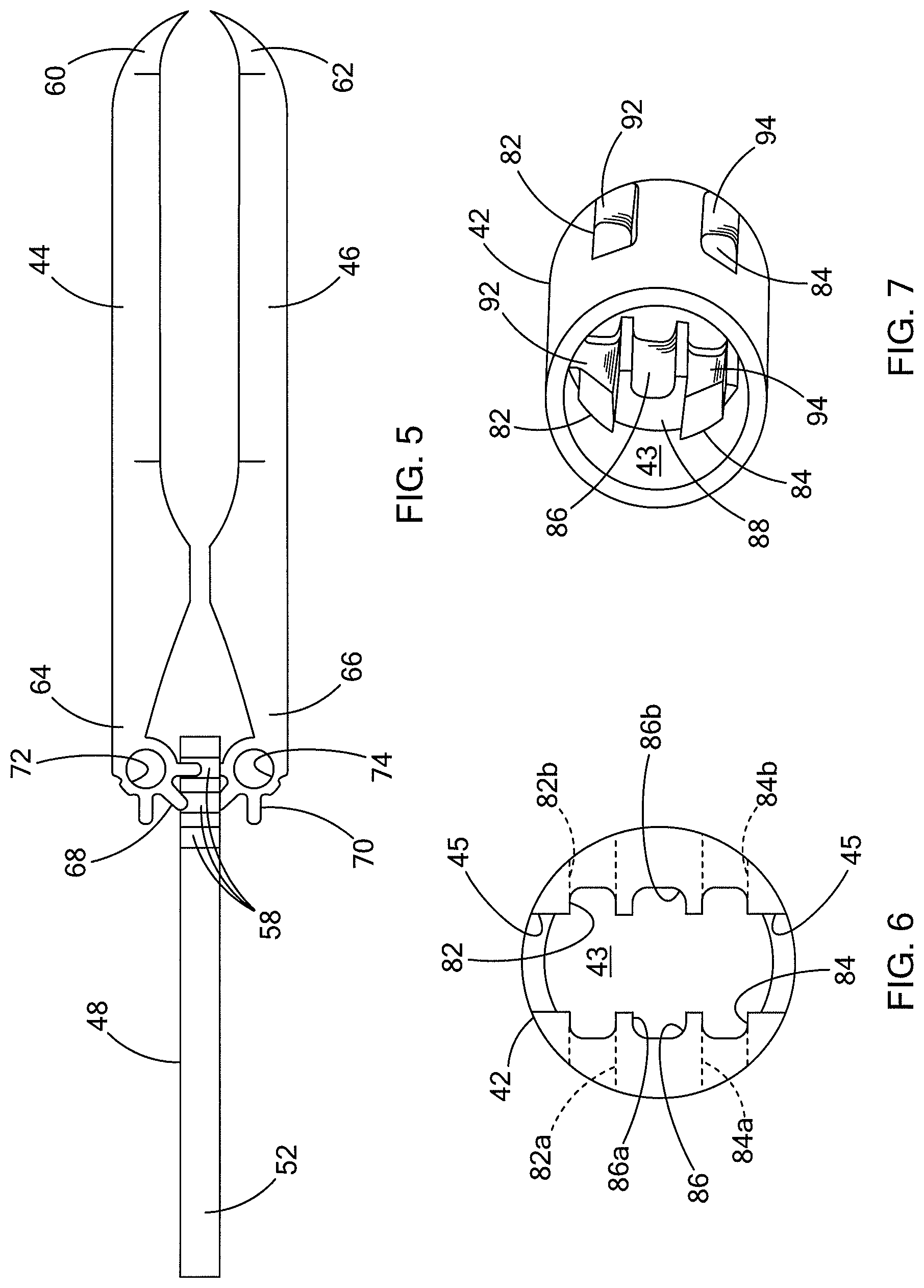
FIG. 5 is a side view of a medical device that is part of the medical system depicted in FIGS. 1-4;
FIG. 6 is a front view of a housing forming a portion of the medical system and device depicted in FIGS. 1-5;
FIG. 7 is a perspective view of the housing depicted in FIG. 6;
FIGS. 8-12 are side views showing operation of the medical system and device depicted in FIGS. 1-5;
FIGS. 13 and 14 are top views, partially in cross-section, depicting operation of the medical system and device depicted in FIGS. 1-4;
FIGS. 15 and 16 are cross-sectional views showing operation of the medical system depicted in FIGS. 1-4; and
FIG. 17 is a side view of a handle forming a portion of the medical system of FIG. 1.
DETAILED DESCRIPTION
The terms "proximal" and "distal" as used herein are intended to have a reference point relative to the user. Specifically, throughout the specification, the terms "distal" and "distally" shall denote a position, direction, or orientation that is generally away from the user, and the terms "proximal" and "proximally" shall denote a position, direction, or orientation that is generally towards the user.
An exemplary medical system 20 having a medical device 40 for engaging tissue T (FIG. 11) is shown in FIGS. 1 through 4. The medical system 20 and device 40 are generally sized and structured for operation through the working channel of an endoscope (not shown) or other scope, although the system 20 and device 40 may also be used in conjunction with other elongate devices such as catheters, fiber-optic visualization systems, needles and the like. Generally, the medical system 20 includes a drive wire 22 slidably housed by a sheath 23 and having a tubular connector 24 at the distal end for selective connection to, and operation of, the medical device 40. As will be described in further detail herein, the medical device 40 generally includes a housing 42 having a first jaw 44 and a second jaw 46 pivotally connected thereto for engaging the tissue T. Generally, the jaws 44, 46 have been shown as forming grasping forceps, although the jaws are intended to be used to clip tissue, e.g. to close an opening or for hemostasis. Accordingly, it will be recognized that the shape and structure of the jaws may take many forms and serve many purposes and functions, all in accordance with the teachings of the present invention.
In the medical system 20, the drive wire 22 slidably extends through the tubular connector 24. Although the term "wire" is used to refer to the drive wire 22, it will be recognized that any elongate control member capable of transmitting longitudinal force over a distance (such as is required in typical endoscopic, laparoscopic and similar procedures) may be used, and this includes plastic rods or tubes, single filament or multi-filament wires and the like. A connection block 26 is slidably fitted within the tubular connector 24 and defines a bore 28 therethrough which slidably receives the drive wire 22. The exterior of the connection block 26 includes a recessed portion 27, and a pin 30 is connected to the tubular connector 24 and fits within the recessed portion 27 to limit the longitudinal movement of the connection block 26.
A distal end of the drive wire 22 defines a distal head 32 that is sized larger than the drive wire 22, and likewise larger than the bore 28 and the connection block 26. As will be described later herein, the distal head 32 is used to slide the connection block 26 within the tubular connector 24 to disconnect the medical device 40 from the medical system 20. As also seen in FIGS. 1-4, the housing 42 of the medical device 40 is a tubular member defining an interior space 43. A proximal end of the housing 42 frictionally receives a distal end of the connection block 26 within the interior space 43 for selective connection therewith.
The internal passageway 43 of the housing 42 also receives the first and second jaws 44, 46 and a driver 48 which is used to interconnect the drive wire 22 to the jaws 44, 46. As best seen in FIGS. 1, 2 and 5, the driver 48 has a proximal portion which defines a socket 50 sized to receive enlarged distal head 32 of the drive wire 22. At the proximal entrance of the socket 50, two deflectable locking tabs 52 are formed which rotate relative to the remainder of the driver 48. The locking tabs 52 may be separately formed and pivotally attached to the driver 48, or may be integrally formed with the driver 48 and of a resilient material which flexes to permit rotation of the locking tabs 52 radially inwardly and radially outwardly. A distal portion of the driver 48 defines a rack 54 for engaging and operating the jaws 44, 46. In the depicted embodiment, the rack 54 includes a central spine 56 having teeth 58 projecting away from the central spine 56 and on opposite sides of the spine 56. One set of teeth 58 on one side of the spine 56 generally operate the first jaw 44 while the other set of teeth 58 on the other side of the spine 56 operate the second jaw 46. It will be recognized that the rack 54 may include a single set of teeth or other geared structures that interface with the jaws 44, 46.
As best seen in FIG. 5, the first and second jaws 44, 46 include distal ends 60, 62 that are structured to grasp and engage tissue, and preferably they have a talon shape as disclosed in 61/141,934 filed Dec. 31, 2008, the disclosure of which is incorporated herein by reference in its entirety. The proximal ends 64, 66 of the first and second jaws 44, 46 each include a pinion gear 68, 70 having a series of teeth. The teeth of the pinion 68, 70 mesh with the teeth of the rack 54 of the driver 48 such that longitudinal translation of the driver 48 induces rotation in the first and second jaws 44, 46 relative to one another. Generally, distal translation of the driver 48 causes the first and second jaws 44, 46 to rotate outwardly away from each other, while proximal retraction of the driver 48 causes the first and second jaws 44, 46 to rotate inwardly toward one another. Pins 80 are fitted through each the proximal ends of the jaws 44, 46, to pivotally connect the jaws to the housing 42. Other structures for forming a pivotal connection may be used, and preferably the pivotal connection is centrally arranged relative to the pinions 68, 70.
In addition to the jaws 44, 46 being pivotally attached to the housing 42, the first and second jaws 44, 46 are also slidably attached to the housing 42. As best seen in FIGS. 6 and 7 (and in conjunction with FIGS. 1-4) the housing 42 defines a first guide surface 82 for the first jaw 44, and a second guide surface 84 for the second jaw 46. As seen in FIG. 3, the first and second guide surfaces 82, 84 are formed by elongated slots 82a, 82b, 84a, 84b formed in opposing sides of the housing 42 which leaves a thickness of the housing 42 exposed to serve as the guide surface. The slots 82a, 82b are aligned to receive the connecting pin 80 of the first jaw 44, and likewise the slots 84a, 84b are aligned to receive the connecting pin 80 of the second jaw 46. The ends of the slots, for example distal ends 92, 94 shown in FIG. 7, serve to restrict the longitudinal movement of the jaws 44, 46 relative to the housing 42. The proximal ends 64, 66 of the jaws 44, 46 include apertures 72, 74 which receive the pins 80 (FIGS. 1, 2 and 3) that are used to slidably and pivotally connect the first and second jaws 44, 46 to the housing 42.
It can also be seen in FIGS. 6 and 7 that the housing 42 defines a third guide surface 86 which guides the longitudinal movement of the driver 48 within the housing 42. The guide surface 86 in the depicted embodiment includes a left guide surface 86a and a right guide surface 86b formed as C-shaped channels. As shown in FIG. 7, the third guide surface 86 transitions from a smaller proximal width to a larger distal width to define a shoulder 88 at the transition, which will be further described hereinbelow with reference to FIGS. 13 and 14. Various combinations of slots, guide surfaces, pins and other slidable engagement structures can be employed to connect the jaws to the housing.
As also shown in FIG. 6, the internal passageway 43 of the housing 42 extends through the distal end of the housing, and through which the first and second jaws 44, 46 can extend. Additionally, as shown in FIGS. 1 and 2, the housing 42 defines opposing slots 45 which are sized to permit the first and second jaws 44, 46 to pass therethrough when they rotate radially outwardly. Accordingly, it is also clear from FIGS. 1 and 2 that the housing 42 serves to block rotation of the first and second jaws 44, 46 when they are entirely or partially contained within the internal passageway 43 of the housing 42.
Operation of the medical device 40 will now be described with reference to FIGS. 8-12. As shown in FIG. 8, the first and second jaws 44, 46 are shown in a retracted position where they are substantially contained within the housing 42. Depending on the application, the distal ends 60, 62 of the jaws 44, 46 may slightly project from the distal end of the housing 42 in their retracted positions, or they may be entirely positioned within the housing 42. When the drive wire 22 is translated distally (to the right on the page in FIG. 8) the distal head 32 engages the driver 48, and since the rack 54 of the driver 48 is meshed with the pinions 68, 70 at the proximal ends 64, 60 of the jaws 44, 46, the driver 48 and jaws 44, 46 slide distally through the housing 42 because the housing 42 blocks their rotation. As previously mentioned, this longitudinal movement is guided by the first and second guide surfaces 82, 84 which receive the pins 80 that slidably and pivotally connect the jaws 44, 46 to the housing 42.
As shown in FIG. 9, the first and second jaws 44, 46 have an extended position where the jaws substantially project from a distal end of the housing 42, and their proximal ends 64, 66 are positioned adjacent the distal end of the housing 42. Accordingly, it will be seen that further distal advancement of drive wire 22, and hence the driver 48, causes the pinion 68 to rotate over the teeth 58 of the rack 54. As best seen in FIG. 10, the first and second jaws 44, 46 rotate radially outwardly from each other into a tissue receiving position. Notably, due to the presence of slots 45 at the distal end of the housing 42, the jaws 44, 46 are permitted to rotate a full 90.degree., thus forming at least a 180.degree. between them. It will be recognized that through the sizing of the slots 45 and the construction of the rack 54 and pinions 68, 70, the first and second jaws 44, 46 may rotate even further away from each other.
In the tissue receiving configuration shown in FIG. 10, the medical device 40 and its jaws 44, 46 may be positioned adjacent tissue T. As shown in FIG. 11, the tissue T may be placed between the first and second jaws 44, 46 and the jaws 44, 46 rotated back towards their position shown in FIG. 9. The tissue T has been shown as a single layer, although multiple layers may be clipped between the jaws 44, 46. Generally, proximal retraction of the drive wire 22 and the driver 48 again causes rotation of the first and second jaws 44, 46 to grasp the tissue T therebetween. As shown in FIG. 12, further proximal retraction of the drive wire 22 and driver 48 will cause the jaws 44, 46 to move longitudinally in a proximal direction (to the left on the page in FIG. 12).
In order for the medical device 40 to serve as a clip and maintain its grasp on the tissue T, or to maintain the clipping of two layers of tissue against each other, the jaws 44, 46 may be locked in position and the drive wire 22 of the medical system 20 disconnected from the medical device 40. As shown in FIG. 13, the third guide surface 86 (which guides the driver 48) includes a proximal portion 86p and a distal portion 86d. The proximal portion 86p of the third guide surface 86 has a width (measured up and down on the page in FIG. 13) that is greater than a width of the distal portion 86d of the third guide 86. As previously discussed, the third guide surface 86 is formed by opposing surfaces or C-shaped channels 86a, 86b of the housing 42. The transition between the proximal portion 86p and distal portion 86d defines a shoulder 88, and namely two shoulders 88a, 88b on opposing sides of the housing 42. The shoulders 88a, 88b are sized and positioned to engage the opposing locking tabs 52 located on the driver 48.
As shown in FIG. 13, when the driver 48 is located within the distal portion 86d of the third guide surface 86, the locking tabs 52 are forced radially inwardly into firm frictional engagement with the drive wire 22. Stated another way, the socket 50 formed by the driver 48 to receive the distal head 32 has an entrance which is narrowed by the inward deflection of the locking tabs 52. In this state depicted in FIG. 13, the drive wire 22 is firmly engaged with the driver 48 and hence the first and second jaws 44, 46. When the drive wire 22 and driver 48 are retracted proximally, for example upon grasping tissue as shown in FIG. 12, the proximal end of the driver 48 is received within the proximal portion 86p of the third guide surface 86 which has a larger width that permits outward movement of the locking tabs 52. Accordingly, in the state depicted in FIG. 14, the locking tabs 52 may be loosely and detachably connected to the distal head 32 of the drive wire 22. That is, the proximal retraction of the jaws 44, 46 will be limited by either the tissue T engaging the distal end of the housing 42, or the pins 80 will abut the proximal ends of the slots 82a, 82b, 84a, 84b defining a first and second guide surfaces 82, 84. As such, when proximal movement of the jaws 44, 46 and the driver 48 are thus limited, further proximal movement of the drive wire 22 and its distal head 32 may be used to withdraw the distal head 32 from the socket 50 of the driver 48. This operation may also be used to further deflect the locking tabs 52 radially outwardly. In the event the natural elasticity of the tissue T tends to pull the jaws 44, 46 out from the housing towards their extended position, the locking tabs 52, 54 will abut the shoulders 88a, 88b of the third guide surface of the housing 42 to prevent further distal movement of the jaws 44, 46.
In one preferred embodiment the locking tabs 52 are plastically deformable, and may be bent around the distal head 32 of the drive wire 22 during manufacture. The driver 48 and its tabs 52 may thus have an initial size to slide within the distal portion 86d of the third guide surface 86, and proximal retraction of the drive wire 22 and distal head 32 of a predetermined force will plastically deform the locking tabs 52 outwardly into a position to engage the shoulders 88a, 88b and lock the clip by preventing distal movement of the jaws 44, 46 therebeyond.
Turning now to FIGS. 15 and 16, upon still further proximal retraction of the drive wire 22 and distal head 32, the enlarged distal head 32 will abut the connection block 26 which is slidably fitted within the tubular connector 24. Sufficient proximal force on the drive wire 22 will overcome the frictional fit between the connection block 26 and the proximal end of the housing 42, thus moving the connection block 26 proximally (to the right on the page of FIGS. 15 and 16) to retract the connection block 26 within the tubular connector 24. An elongate sheath 23 slidably encases the drive wire 22, and extends proximally therealong to the proximal end of the device. The sheath 23 can be used to provide a counterforce on the connector 24 and housing 42 while proximally retracting the drive wire 22 and connection block 26. Accordingly, the drive wire 22, tubular connector 24 and connection block 26 may be fully disconnected from the medical device 40, thereby leaving the first and second jaws 44, 46 and the housing 42 in a state having the tissue T clipped between the jaws 44, 46 and retained in vivo.
It will be recognized by those skilled in the art that the drive wire 22 and its distal head 32 could again be connected to the driver 48 and its socket 50, thus permitting additional manipulation of the medical device to adjust the clipped tissue T. Likewise, additional medical devices may be attached to the drive wire 22 and tubular connector 24 of the medical system 20 for deployment of the additional medical devices, e.g. multiple devices 40 for clipping the tissue T may be used to close a perforation or achieve hemostasis. Generally, the support ring 34 (FIGS. 1-4) fixed on the drive wire 22 can be used to limit the distal movement of the drive wire 22, and can be distally advanced to a position abutting the connection block 26. As such, the drive wire 22 and support ring 34 can be used to push the connection block 26 distally out of the tubular connector 24 so that it can be attached to the housing (e.g. 42) of a new medical device (e.g. 40), or the previously placed medical device 40. Alternatively, the user may manually press (i.e. with fingers or a tool) the connection block 26 distally out of the tubular connector 24 for connection to another medical device.
The medical system 20 also includes a proximal end device for operating the medical device 40, and preferably a handle 90 as shown. The handle 90 includes an outer member 92 slidably receiving an inner member 94. The outer member 92 is a tubular member defining a passageway that receives the inner member 94, and includes a spool 96 formed on the outer surface which is shaped to be gripped by the fingers of the medical professional. The inner member 94 may be tubular or rod shaped, and includes a thumb ring 98 at its proximal end for gripping by the professional. The outer member 92 is attached to the sheath 23, which is preferably a coated coiled wire catheter as is known in the art. The inner member 94 is connected to the drive wire 22. In this way, translation of the inner member 94 and thumb ring 98 relative to the outer member 92 and spool 96 causes relative translation of the drive wire 22 relative to the sheath 23. This in turn operates the medical device 40, namely the clip defined by the housing 42 and jaws 44, 46 which rotate relative thereto, as previously described. A side port 100 may also be provided in communication with the interior passageway of the outer member 92 and sheath 23 for injection of fluids or other agents for facilitating hemostasis, closure, cleaning or other aspects related to the methods described above.
It will be recognized by those skilled in the art that, while the methods described above generally include placing the tissue devices in tissue through an internal bodily lumen, it will be recognized that the systems, devices and methods may be used on any layer of material (e.g. fabrics, cloth, polymers, elastomers, plastics and rubber) that may or may not be associated with a human or animal body and a bodily lumen. For example, the systems, devices and methods can find use in laboratory and industrial settings for clipping (or cutting, ligating, grasping) one or more layers of material that may or may not find application to the human or animal body, and likewise closing holes or perforations in layers of material that are not bodily tissue. Some examples include sewing or stitching and related manufacturing, working with synthetic tissues, connecting or repairing polymeric sheets, animal studies, veterinary applications, and post-mortem activities.
The foregoing description of various embodiments of the invention has been presented for purposes of illustration and description. It is not intended to be exhaustive or to limit the invention to the precise embodiments disclosed. Numerous modifications or variations are possible in light of the above teachings. The embodiments discussed were chosen and described to provide the best illustration of the principles of the invention and its practical application to thereby enable one of ordinary skill in the art to utilize the invention in various embodiments and with various modifications as are suited to the particular use contemplated. All such modifications and variations are within the scope of the invention as determined by the appended claims when interpreted in accordance with the breadth to which they are fairly, legally, and equitably entitled.
* * * * *
References
D00000
D00001
D00002
D00003
D00004
D00005
D00006
D00007
D00008
D00009
XML
uspto.report is an independent third-party trademark research tool that is not affiliated, endorsed, or sponsored by the United States Patent and Trademark Office (USPTO) or any other governmental organization. The information provided by uspto.report is based on publicly available data at the time of writing and is intended for informational purposes only.
While we strive to provide accurate and up-to-date information, we do not guarantee the accuracy, completeness, reliability, or suitability of the information displayed on this site. The use of this site is at your own risk. Any reliance you place on such information is therefore strictly at your own risk.
All official trademark data, including owner information, should be verified by visiting the official USPTO website at www.uspto.gov. This site is not intended to replace professional legal advice and should not be used as a substitute for consulting with a legal professional who is knowledgeable about trademark law.