Thermal barrier coating, turbine member, and gas turbine
Tanigawa , et al. October 20, 2
U.S. patent number 10,808,308 [Application Number 16/306,635] was granted by the patent office on 2020-10-20 for thermal barrier coating, turbine member, and gas turbine. This patent grant is currently assigned to MITSUBISHI HEAVY INDUSTRIES, LTD.. The grantee listed for this patent is MITSUBISHI HEAVY INDUSTRIES, LTD.. Invention is credited to Daisuke Kudo, Masahiko Mega, Yoshifumi Okajima, Shuji Tanigawa, Taiji Torigoe.


| United States Patent | 10,808,308 |
| Tanigawa , et al. | October 20, 2020 |
Thermal barrier coating, turbine member, and gas turbine
Abstract
A thermal barrier coating includes a highly porous layer and a dense layer. The highly porous layer is formed on a heat-resistant base, is made of ceramic, has pores, has a layer thickness of equal to or larger than 0.3 mm and equal to or smaller than 1.0 mm, and has a pore ratio of equal to or higher than 1 vol % and equal to or lower than 30 vol %. The dense layer is formed on the highly porous layer, is made of ceramic, has a pore ratio of equal to or lower than 0.9 vol % that is equal to or lower than the pore ratio of the highly porous layer, and has a layer thickness of equal to or smaller than 0.05 mm.
| Inventors: | Tanigawa; Shuji (Tokyo, JP), Mega; Masahiko (Tokyo, JP), Torigoe; Taiji (Tokyo, JP), Okajima; Yoshifumi (Tokyo, JP), Kudo; Daisuke (Tokyo, JP) | ||||||||||
|---|---|---|---|---|---|---|---|---|---|---|---|
| Applicant: |
|
||||||||||
| Assignee: | MITSUBISHI HEAVY INDUSTRIES,
LTD. (Tokyo, JP) |
||||||||||
| Family ID: | 60578616 | ||||||||||
| Appl. No.: | 16/306,635 | ||||||||||
| Filed: | June 6, 2017 | ||||||||||
| PCT Filed: | June 06, 2017 | ||||||||||
| PCT No.: | PCT/JP2017/020912 | ||||||||||
| 371(c)(1),(2),(4) Date: | December 03, 2018 | ||||||||||
| PCT Pub. No.: | WO2017/213113 | ||||||||||
| PCT Pub. Date: | December 14, 2017 |
Prior Publication Data
| Document Identifier | Publication Date | |
|---|---|---|
| US 20190119804 A1 | Apr 25, 2019 | |
Foreign Application Priority Data
| Jun 8, 2016 [JP] | 2016-114261 | |||
| Current U.S. Class: | 1/1 |
| Current CPC Class: | C23C 4/073 (20160101); C23C 4/11 (20160101); F01D 9/041 (20130101); C23C 4/18 (20130101); C23C 28/3455 (20130101); C04B 41/526 (20130101); F01D 25/145 (20130101); C23C 4/134 (20160101); C04B 41/524 (20130101); F01D 9/02 (20130101); F01D 5/288 (20130101); C04B 41/4527 (20130101); C04B 41/522 (20130101); C23C 28/042 (20130101); C23C 28/048 (20130101); F01D 5/28 (20130101); F01D 5/286 (20130101); C23C 24/04 (20130101); F05D 2300/6111 (20130101); F05D 2240/24 (20130101); Y10T 428/12618 (20150115); Y10T 428/249981 (20150401); F05D 2230/312 (20130101); F05D 2300/701 (20130101); F02C 7/00 (20130101); F05D 2300/20 (20130101); F23R 3/42 (20130101); Y10T 428/24992 (20150115); F05D 2300/134 (20130101); F05D 2260/95 (20130101); Y10T 428/249989 (20150401); F05D 2300/514 (20130101); F05D 2230/90 (20130101); Y10T 428/24471 (20150115); F05D 2300/611 (20130101); Y10T 428/24983 (20150115); F05B 2230/90 (20130101); F05D 2300/2118 (20130101); Y10T 428/12611 (20150115); Y10T 428/24331 (20150115); F05D 2220/32 (20130101); F05D 2230/30 (20130101); F05D 2300/506 (20130101); F05D 2240/12 (20130101); C04B 41/5042 (20130101); C23C 28/3215 (20130101); Y10T 428/2495 (20150115); F05D 2300/21 (20130101); Y10T 428/24999 (20150401); C04B 41/0036 (20130101); C04B 41/5041 (20130101); C23C 16/4486 (20130101); F05D 2300/5023 (20130101); F02C 7/24 (20130101) |
| Current International Class: | C23C 4/11 (20160101); C23C 4/134 (20160101); C23C 4/073 (20160101); F01D 9/04 (20060101); F01D 25/14 (20060101); C04B 41/45 (20060101); C04B 41/52 (20060101); C23C 28/00 (20060101); C23C 28/04 (20060101); F01D 5/28 (20060101); C23C 4/18 (20060101); C04B 41/50 (20060101); C23C 24/04 (20060101); C23C 16/448 (20060101); F02C 7/00 (20060101); F23R 3/42 (20060101); F02C 7/24 (20060101); C04B 41/00 (20060101) |
References Cited [Referenced By]
U.S. Patent Documents
| 4814575 | March 1989 | Petitbon |
| 5169674 | December 1992 | Miller |
| 5350599 | September 1994 | Rigney |
| 5484980 | January 1996 | Pratt |
| 5683825 | November 1997 | Bruce |
| 5955182 | September 1999 | Yasuda |
| 6060177 | May 2000 | Bornstein |
| 6071627 | June 2000 | Yasuda |
| 6165600 | December 2000 | Ivkovich, Jr. |
| 6511762 | January 2003 | Lee |
| 6558814 | May 2003 | Spitsberg |
| 6703137 | March 2004 | Subramanian |
| 6875529 | April 2005 | Spitsberg |
| 7833586 | November 2010 | Margolies |
| 7862901 | January 2011 | Darolia |
| 2002/0141868 | October 2002 | Lee |
| 2002/0160189 | October 2002 | Wataya |
| 2003/0138658 | July 2003 | Taylor |
| 2004/0002221 | January 2004 | O'Donnell |
| 2004/0028941 | February 2004 | Lane |
| 2004/0110016 | June 2004 | Hamaya |
| 2004/0110021 | June 2004 | Seth |
| 2004/0115406 | June 2004 | Nagaraj |
| 2004/0126599 | July 2004 | Wigren |
| 2004/0156724 | August 2004 | Torigoe |
| 2004/0229031 | November 2004 | Gell |
| 2004/0229078 | November 2004 | Maeda |
| 2005/0013994 | January 2005 | Strangman |
| 2005/0112412 | May 2005 | Darolia |
| 2005/0136249 | June 2005 | Arikawa |
| 2005/0221109 | October 2005 | Torigoe |
| 2006/0019119 | January 2006 | Spitsberg |
| 2006/0151856 | July 2006 | Torigoe |
| 2007/0026246 | February 2007 | Harada |
| 2007/0036997 | February 2007 | Floyd |
| 2007/0077456 | April 2007 | Kitamura |
| 2007/0082131 | April 2007 | Doesburg et al. |
| 2007/0098912 | May 2007 | Raybould |
| 2007/0140840 | June 2007 | Schmitz |
| 2007/0148478 | June 2007 | Schmitz |
| 2007/0172703 | July 2007 | Freling et al. |
| 2007/0215283 | September 2007 | Kobayashi |
| 2007/0218302 | September 2007 | Kobayashi |
| 2008/0044662 | February 2008 | Schlichting |
| 2008/0145629 | June 2008 | Anoshkina |
| 2008/0176097 | July 2008 | Schlichting |
| 2008/0199709 | August 2008 | Ishiwata |
| 2008/0220209 | September 2008 | Taylor |
| 2009/0053069 | February 2009 | Barnikel |
| 2009/0214825 | August 2009 | Sun et al. |
| 2009/0258214 | October 2009 | Bayer |
| 2009/0280298 | November 2009 | Rosenzweig |
| 2009/0311508 | December 2009 | Stamm |
| 2010/0136349 | June 2010 | Lee |
| 2010/0242477 | September 2010 | Duval |
| 2010/0272982 | October 2010 | Dickinson |
| 2010/0296943 | November 2010 | Lee |
| 2010/0304084 | December 2010 | Anand |
| 2010/0304181 | December 2010 | Anand |
| 2010/0330391 | December 2010 | Arikawa |
| 2011/0086177 | April 2011 | Ma |
| 2011/0236657 | September 2011 | Feist |
| 2011/0244216 | October 2011 | Meyer |
| 2011/0300357 | December 2011 | Witz et al. |
| 2012/0167573 | July 2012 | Belousov |
| 2012/0183790 | July 2012 | Petorak |
| 2012/0196139 | August 2012 | Petorak |
| 2012/0231211 | September 2012 | von Niessen |
| 2012/0276352 | November 2012 | Liu |
| 2012/0276355 | November 2012 | Sansom |
| 2013/0052451 | February 2013 | Sano |
| 2013/0095344 | April 2013 | Nagaraj |
| 2013/0101745 | April 2013 | Meillot |
| 2013/0137051 | May 2013 | Beyer |
| 2013/0186304 | July 2013 | Pabla |
| 2013/0202912 | August 2013 | Torigoe |
| 2013/0260132 | October 2013 | Hazel |
| 2013/0344349 | December 2013 | Hugot |
| 2014/0220378 | August 2014 | Nagaraj |
| 2014/0302247 | October 2014 | Inaba |
| 2014/0308479 | October 2014 | Parakala |
| 2014/0315006 | October 2014 | Stamm |
| 2014/0360407 | December 2014 | Kitamura |
| 2015/0044444 | February 2015 | Gell |
| 2015/0147524 | May 2015 | Petorak |
| 2015/0197456 | July 2015 | Oboodi |
| 2016/0010471 | January 2016 | Pabla |
| 2016/0017475 | January 2016 | Hazel |
| 2016/0068941 | March 2016 | Nair |
| 2016/0251971 | September 2016 | Dusterhoft |
| 2016/0254125 | September 2016 | Huang |
| 2017/0073277 | March 2017 | Shim |
| 2017/0250057 | August 2017 | Simpson |
| 2017/0298519 | October 2017 | Degel |
| 2018/0030584 | February 2018 | Inoue |
| 2018/0030589 | February 2018 | Sun |
| 2018/0135157 | May 2018 | Jeong |
| 101004142 | Jul 2007 | CN | |||
| 101081735 | Dec 2007 | CN | |||
| 101265561 | Sep 2008 | CN | |||
| 101994078 | Mar 2011 | CN | |||
| 102084020 | Jun 2011 | CN | |||
| 102245810 | Nov 2011 | CN | |||
| 102015200076 | Jul 2016 | DE | |||
| 2000557 | Dec 2008 | EP | |||
| 59-096273 | Jun 1984 | JP | |||
| 61030658 | Feb 1986 | JP | |||
| 61104062 | May 1986 | JP | |||
| 63004051 | Jan 1988 | JP | |||
| 63241152 | Oct 1988 | JP | |||
| 01-104756 | Apr 1989 | JP | |||
| 01268854 | Oct 1989 | JP | |||
| 02004951 | Jan 1990 | JP | |||
| 02274863 | Nov 1990 | JP | |||
| 06306639 | Nov 1994 | JP | |||
| 07243018 | Sep 1995 | JP | |||
| 07331456 | Dec 1995 | JP | |||
| 09067662 | Mar 1997 | JP | |||
| 11061438 | Mar 1999 | JP | |||
| 2000144365 | May 2000 | JP | |||
| 2002069607 | Mar 2002 | JP | |||
| 2003160852 | Jun 2003 | JP | |||
| 2005163172 | Jun 2005 | JP | |||
| 2005163185 | Jun 2005 | JP | |||
| 2006144061 | Jun 2006 | JP | |||
| 2008127614 | Jun 2008 | JP | |||
| 2008266724 | Nov 2008 | JP | |||
| 2009041059 | Feb 2009 | JP | |||
| 2009293058 | Dec 2009 | JP | |||
| 2010-242223 | Oct 2010 | JP | |||
| 2011-140693 | Jul 2011 | JP | |||
| 2011167994 | Sep 2011 | JP | |||
| 2012067364 | Apr 2012 | JP | |||
| 2013-185202 | Sep 2013 | JP | |||
| 2014098175 | May 2014 | JP | |||
| 5554488 | Jun 2014 | JP | |||
| 5737996 | May 2015 | JP | |||
| 2015113255 | Jun 2015 | JP | |||
| 2015175315 | Oct 2015 | JP | |||
| 2015-218379 | Dec 2015 | JP | |||
| 20110101758 | Sep 2011 | KR | |||
| WO-2005071228 | Aug 2005 | WO | |||
| WO-2006099869 | Sep 2006 | WO | |||
| WO-2006128424 | Dec 2006 | WO | |||
| WO-2014123323 | Aug 2014 | WO | |||
| WO-2015165662 | Nov 2015 | WO | |||
| WO-2016147282 | Sep 2016 | WO | |||
Other References
|
Machine Translation of JP 07243018 A, Sep. 1995 (Year: 1995). cited by examiner . Machine Translation of JP-09067662-A, Mar. 1997 (Year: 1997). cited by examiner . Machine Translation of JP-2000144365-A, May 2000 (Year: 2000). cited by examiner . Machine Translation of JP-2002069607-A, Mar. 2002 (Year: 2002). cited by examiner . Machine Translation of JP-2003160852-A, Jun. 2003 (Year: 2003). cited by examiner . Machine Translation of JP-2008266724-A, Nov. 2008 (Year: 2008). cited by examiner . Saral et al., Thermal cycle properties of plasma sprayed YSZ/Al2O3 thermal barrier coatings, Oct. 2009, Surface Engineering, vol. 20, Issue 7, pp. 541-547 (Year: 2009). cited by examiner . Zhu et al., Thin Yttria-Stabilized Zirconia Coatings Deposited by Low-Energy Plasma Spraying Under Very Low Pressure Condition, Sep. 2011, Journal of Thermal Spray Technology, vol. 20, Issue 5, pp. 1118-1124 (Year: 2011). cited by examiner . Kern et al., Abstract for Ytterbia (2.25 mol.-%) stabilised zirconia (Yb-TZP) manufactured from coated nanopowder, Aug. 2012, Advances in Applied Ceramics, vol. 111, Issues 5&6, pp. 275-279 (Year: 2012). cited by examiner . He et al., Characterization of Yttria-Stabilized Zirconia Coatings Deposited by Low-Pressure Plasma Spraying, Feb. 2016, Journal of Thermal Spray Technology, vol. 25, Issue 3, pp. 558-566 (Year: 2016). cited by examiner . Xiaorui et al., Mechanical properties of high-temperature-degraded yttria-stabilized zirconia, May 2014, Acta Materialia, vol. 69, pp. 397-406 (Year: 2014). cited by examiner . Keshavarz et al., Mechanical properties of stabilized zirconia nanocrystalline EB-PVD coating evaluated by micro and nano indentation, Dec. 2013, Journal of Advanced Ceramics, vol. 2, pp. 333-340 (Year: 2013). cited by examiner . Guo et al., Atmospheric plasma sprayed thick thermal barrier coatings with high segmentation crack density, Sep. 2004, Surface and Coatings Technology, vol. 186, Issue 3, pp. 353-363 (Year: 2004). cited by examiner . Iwasawa et al., Plasma-Resistant Dense Yttrium Oxide Film Prepared by Aerosol Deposition Process, Jun. 2007, Journal of the American Ceramic Society, vol. 90, Issue 8, pp. 2327-2332 (Year: 2007). cited by examiner . Karabas et al.. Effect of Air Plasma Spray Parameters on the Properties of YSZ and CYSZ Thermal Barrier Coatings, Jan. 2016, Journal of the Australian Ceramic Society, vol. 52, pp. 175-182 (Year: 2016). cited by examiner . International Search Report dated Jul. 11, 2018 in International (PCT) Application No. PCT/JP2017/020912. cited by applicant . Written Opinion of the International Searching Authority dated Jul. 11, 2017 in International (PCT) Application No. PCT/JP2017/020912, with English-language translation. cited by applicant . Oguma et al., "Development of Advanced Materials and Manufacturing Technology for High-efficiency Gas Turbine", Mitsubishi Juko Giho Shinseihin-Shingijutsu Tokushu, 2015, vol. 52, No. 4, pp. 5-14. cited by applicant . Office Action dated Mar. 18, 2020 in corresponding Chinese Patent Application No. 201780034914.1, with an English translation. cited by applicant. |
Primary Examiner: Vonch; Jeffrey A
Attorney, Agent or Firm: Wenderoth, Lind & Ponack, L.L.P.
Claims
The invention claimed is:
1. A thermal barrier coating comprising: a highly porous layer formed on a heat-resistant base, the highly porous layer being made of ceramic; and having pores, the highly porous layer having a layer thickness of equal to or larger than 0.3 mm and equal to or smaller than 1.0 mm, and having a pore ratio of equal to or higher than 1 vol % and equal to or lower than 30 vol %, the highly porous layer being made of an ytterbia-stabilized zirconia material; a dense layer formed on the highly porous layer, the dense layer having a pore ratio of equal to or lower than 0.9 vol % that is lower than the pore ratio of the highly porous layer, and the dense layer having a layer thickness of equal to or smaller than 0.05 mm and being made of an ytterbia-stabilized zirconia material or an yttria-stabilized zirconia material; and a molten layer formed on the dense layer by melting a portion of the dense layer; wherein a thickness of the dense layer remaining under the molten layer is equal to or larger than 0.01 mm, and the molten layer has a thickness of equal to or larger than the thickness of the dense layer and no greater than 0.04 mm.
2. The thermal barrier coating according to claim 1, further comprising: a metal bonding layer formed between the heat-resistant base and the highly porous layer.
3. The thermal barrier coating according to claim 2, wherein the metal bonding layer is made of an MCrAlY alloy, wherein M is a metal comprising Ni, Co, Fe, or a combination thereof.
4. The thermal barrier coating according to claim 1, wherein the dense layer is made of the ytterbia-stabilized zirconia material.
5. The thermal barrier coating according to claim 1, wherein the dense layer has a Vickers hardness of equal to or higher than 800 Hv.
6. The thermal barrier coating according to claim 5, wherein the highly porous layer has a Vickers hardness of equal to or higher than 800 Hv.
7. The thermal barrier coating according to claim 1, wherein the highly porous layer has vertical cracks in a surface where the dense layer is provided.
8. The thermal barrier coating according to claim 7, wherein the vertical cracks of the highly porous layer have one to ten vertical cracks per mm in a surface where the dense layer is provided.
9. The thermal barrier coating according to claim 1, wherein the dense layer has a particle size distribution in which the average particle diameter of ceramic is equal to or smaller than 20 .mu.m.
10. A turbine member comprising the thermal barrier coating according to claim 1 on a surface.
11. The turbine member of claim 7, wherein the turbine member is a compressor blade or vane.
12. A gas turbine comprising the turbine member according to claim 10.
13. A method of producing a thermal barrier coating comprising: forming a highly porous layer on a heat-resistant base by atmospheric plasma spraying, the highly porous layer being made of ceramic and having pores, the highly porous layer having a layer thickness of equal to or larger than 0.3 mm and equal to or smaller than 1.0 mm, and having a pore ratio of equal to or higher than 1 vol % and equal to or lower than 30 vol %; forming a dense layer on the highly porous layer by atmospheric plasma spraying, cold spraying method, or an aerosol deposition method, the dense layer being made of ceramic and having a pore ratio of equal to or lower than 0.9 vol % that is lower than the pore ratio of the highly porous layer, and the dense layer having a layer thickness of equal to or smaller than 0.05 mm; melting a portion of the dense layer to form a molten layer on the dense layer; wherein a thickness of the dense layer remaining under the molten layer is equal to or larger than 0.01 mm, and the molten layer has a thickness of equal to or larger than the thickness of the dense layer and no greater than 0.04 mm.
14. The method of producing a thermal barrier coating according to claim 13, wherein the dense layer is formed on a surface of the highly porous layer by short-distance spraying of equal to or shorter than 100 mm by the atmospheric plasma spraying.
15. The method of producing a thermal barrier coating according to claim 13, wherein melting the portion of the dense layer is performed by laser scanning the outer surface of the dense layer.
16. The method of producing a thermal barrier coating according to claim 13, further comprising: prior to forming the highly porous layer, forming a metal bonding layer on the heat resistant base by low pressure plasma spraying (LPPS), high velocity oxygen fuel (HVOF) spraying, or atmospheric plasma spraying (APS).
Description
FIELD
The present invention relates to a thermal barrier coating, and a turbine member and a gas turbine including the thermal barrier coating.
BACKGROUND
Japanese Patent No. 5737996, for example, describes a thermal barrier coating produced by a method for producing a thermal barrier coating. The method for producing the thermal barrier coating includes a step of forming a metal bonding layer on a heat-resistant base and a step of forming a ceramic layer on the metal bonding layer. The step of forming the ceramic layer includes a stage of forming a highly porous layer including pores by thermal spraying on the metal bonding layer, a stage of forming a dense layer having a structure denser than that of the highly porous layer on the highly porous layer, and a stage of polishing the top surface of the dense layer such that the dense layer has a predetermined thickness.
Japanese Patent No. 5554488, for example, describes a coating system including a thermal barrier coating containing a chemically stabilized zirconia material provided on a metal component and a thermally sprayed alumina-based coating disposed on the thermal barrier coating. The alumina-based coating contains at least 87 wt % alumina based on the total weight of the alumina-based coating and has a thickness effective to increase the melting point of a contaminant composition containing mixed calcium-magnesium-aluminum-silicon-oxides. The average surface roughness of the thermally sprayed alumina-based coating is smaller than 4.0 .mu.m to approximately 0.75 .mu.m.
Japanese Patent No. 5737996 describes a typical conventional thermal barrier coating (TBC) having a two-layer structure in which a metal bonding layer and a ceramic layer are formed in order. An object of the conventional TBC is to secure a high heat-shielding property and has high erosion resistance and a smooth surface. As described above, Japanese Patent No. 5737996 provides the ceramic layer including a highly porous layer and a dense layer formed on the highly porous layer.
In oil-burning gas turbine plants using petroleum as fuel, however, turbine blades and turbine vanes serving as turbine members are exposed to an environment including high-temperature corrosive substances (e.g., Na.sub.2SO.sub.4 and CaSO.sub.4). The high-temperature corrosive substances penetrate into a TBC, thereby reducing the Life of the TBC. As a result, the TBC may possibly peel off.
To address the disadvantage described above, an object of the present invention is to provide a thermal barrier coating, a turbine member, and a gas turbine that can secure the heat-shielding property and the erosion resistance and increase the corrosion resistance.
SUMMARY OF THE INVENTION
To achieve the object described above, a thermal barrier coating according to an aspect of the present invention includes a highly porous layer formed on a heat-resistant base, made of ceramic, and having pores; and a dense layer formed on the highly porous layer, made of ceramic, having a pore ratio of equal to or lower than 0.9 vol % that is equal to or lower than the pore ratio of the highly porous layer, having a layer thickness of equal to or smaller than 0.05 mm, and having a Vickers hardness of equal to or higher than 800 Hv.
This thermal barrier coating can secure the heat-shielding property, for the heat-resistance base, in the highly porous layer. With the dense layer formed on the highly porous layer and serving as a hard film having denseness in the pore ratio and the Vickers hardness, the thermal barrier coating can secure the erosion resistance. Having denseness in the pore ratio of the dense layer can prevent penetration of corrosive components and increase the corrosion resistance. As a result, the thermal barrier coating can have higher durability in a high-temperature corrosive environment.
To achieve the object described above, a thermal barrier coating according to an aspect of the present invention includes a metal bonding layer formed on a heat-resistant base; a highly porous layer formed on the metal bonding layer, made of ceramic, and having pores; and a dense layer formed on the highly porous layer, made of ceramic, having a pore ratio of equal to or lower than 0.9 vol % that is equal to or lower than the pore ratio of the highly porous layer, having a layer thickness of equal to or smaller than 0.05 mm, and having a Vickers hardness of equal to or higher than 800 Hv.
This thermal barrier coating can secure the heat-shielding property, for the heat-resistant base, in the highly porous layer bonded to the heat-resistant base with the metal bonding layer. With the dense layer formed on the highly porous layer and serving as a hard film having denseness in the pore ratio and the Vickers hardness, the thermal barrier coating can secure the erosion resistance. Having denseness in the pore ratio of the dense layer can prevent penetration of corrosive components and increase the corrosion resistance. As a result, the thermal barrier coating can have higher durability in a high-temperature corrosive environment.
Further, the thermal barrier coating according to an aspect of the present invention preferably further includes a molten layer formed on the dense layer by melting the dense layer.
In this thermal barrier coating, the molten layer is formed by melting the outer layer of the dense layer having a pore ratio of equal to or lower than 0.9 vol %, and the melting makes the surface of the dense layer denser. Consequently, the thermal barrier coating can further increase the corrosion resistance. As a result, the thermal barrier coating can have higher durability in a high-temperature corrosive environment.
Further, in the thermal barrier coating according to an aspect of the present invention, the layer thickness of the dense layer under the molten layer is preferably equal to or larger than 0.01 mm.
In this thermal barrier coating, while the molten layer may possibly have lower strength because of its high denseness, such a reduction in the strength can be suppressed by making the layer thickness of the dense layer under the molten layer equal to or larger than 0.01 mm.
Further, in the thermal barrier coating according to an aspect of the present invention, it is preferable that one of the highly porous layer and the dense layer is made of an yttria-stabilized zirconia material, and the other is made of an vtterbia-stabilized zirconia material.
In this thermal barrier coating, one of the highly porous layer and the dense layer is made of the yttria-stabilized zirconia material, and the other thereof is made of the ytterbia-stabilized zirconia material. With this configuration, the thermal barrier coating can significantly secure the heat-shielding property, for the heat-resistant base, in the highly porous layer. In addition, the thermal barrier coating can secure the erosion resistance in the dense layer and significantly increase the corrosion resistance. As a result, the thermal barrier coating can have higher durability in a high-temperature corrosive environment.
Further, in the thermal barrier coating according to an aspect of the present invention, the highly porous layer and the dense layer are preferably made of an ytterbia-stabilized zirconia material.
In this thermal harrier coating, the highly porous layer and the dense layer are made of the ytterbia-stabilized zirconia material. Consequently, the thermal barrier coating can have high heat-shielding, durability, and corrosion-resistant functions.
To achieve the object described above, a turbine member according to an aspect of the present invention includes any one of the thermal barrier coatings described above on a surface.
This turbine member includes any one of the thermal barrier coatings described above having a high heat-shielding property, high erosion resistance, and high corrosion resistance. Consequently, the turbine member can be applied to a gas turbine member used at 1600 degrees C., for example.
To achieve the object described above, a gas turbine according to an aspect of the present invention includes the turbine member described above.
This gas turbine includes the gas turbine member having a high heat-shielding property, high erosion resistance, and high corrosion resistance. Consequently, the gas turbine has higher durability.
Advantageous Effects of Invention
The present invention can secure the heat shielding property and the erosion resistance and increase the corrosion resistance.
BRIEF DESCRIPTION OF DRAWINGS
FIG. 1 is a schematic configuration diagram of a gas turbine according to an embodiment of the present invention.
FIG. 2 is a schematic sectional diagram of a thermal barrier coating according to the embodiment of the present invention.
FIG. 3 is a schematic sectional diagram of another example of the thermal barrier coating according to the embodiment of the present invention.
DESCRIPTION OF EMBODIMENTS
Exemplary embodiments according to the present invention are described below in greater detail with reference to the accompanying drawings. The embodiments are not intended to limit the present invention. Components according to the embodiments below include components capable of being easily replaced by those skilled in the art and components substantially identical therewith.
FIG. 1 is a schematic configuration diagram of a gas turbine according to the present embodiment.
While the present embodiment describes as an example an industrial gas turbine 10 illustrated in FIG. 1, examples of the embodiment include other gas turbines, such as aviation gas turbines.
As illustrated in FIG. 1, the gas turbine 10 includes a compressor 1, combustors 2, and a turbine 3. In the gas turbine 10, a turbine shaft 4 serving as a rotating shaft is disposed penetrating the center of the compressor 1, the combustors 2, and the turbine 3. The compressor 1, the combustors 2, and the turbine 3 are provided in a row in this order from the upstream side to the downstream side of an air flow along an axis R of the turbine shaft 4. In the following description, an axial direction indicates a direction parallel to the axis R. A circumferential direction indicates a direction of circumference about the axis R. A radial direction indicates a direction orthogonal to the axis R.
The compressor 1 compresses air to generate compressed air. The compressor 1 includes compressor vanes 13 and compressor blades 14 in a compressor casing 12 having an air intake port 11 through which air is taken in. The compressor vanes 13 are attached to the compressor casing 12 and provided in a row in the circumferential direction. The compressor blades 14 are attached to the turbine shaft 4 and provided in a row in the circumferential direction. The compressor vanes 13 and the compressor blades 14 are alternately provided along the axial direction.
The combustors 2 supply fuel to compressed air compressed by the compressor 1, thereby generating a high-temperature and high-pressure combustion gas. The combustors 2 each include an inner cylinder 21, a transition piece 22, and an outer casing 23. The inner cylinder 21 serving as a combustion chamber mixes and combusts the compressed air and the fuel. The transition piece 22 guides the combustion gas from the inner cylinder 21 to the turbine 3. The outer casing 23 covers the outer periphery of the inner cylinder 21 and defines an air passage 25 that guides the compressed air from the compressor 1 to the inner cylinder 21. A plurality of (e.g., 16) combustors 2 are provided in a row in the circumferential direction in a combustor casing 24.
The turbine 3 generates rotational power from the combustion gas combusted by the combustors 2. The turbine 3 includes turbine vanes 32 and turbine blades 33 in a turbine casing 31. The turbine vanes 32 are attached to the turbine casing 31 and provided in a row in the circumferential direction. The turbine blades 33 are attached to the turbine shaft 4 and provided in a row in the circumferential direction. The turbine vanes 32 and the turbine blades 33 are alternately provided along the axial direction. Behind the turbine casing 31, a flue gas chamber 34 including a flue gas diffuser 34a communicating with the turbine 3 is provided.
The turbine shaft 4 is provided rotatably about the axis R with one end on the compressor 1 side supported by a bear in 41 and the other end on the flue gas chamber 34 side supported by a bearing 42. The end of the turbine shaft 4 on the compressor 1 side is connected to a drive shaft of a generator, which is not illustrated.
In the gas turbine 10 as described above, air taken in through the air intake port 11 of the compressor 1 passes by the compressor vanes 13 and the compressor blades 14 and is compressed, thereby becoming high-temperature and high-pressure compressed air. The combustors 2 mix and combust fuel and the compressed air, thereby generating a high-temperature and high-pressure combustion gas. The combustion gas passes by the turbine vanes 32 and the turbine blades 33 of the turbine 3, thereby rotating and driving the turbine shaft 4. The rotational power is supplied to the generator connected to the turbine shaft 4, thereby generating electricity. The flue gas resulting from rotating and driving the turbine shaft 4 passes through the flue gas diffuser 34a of the flue gas chamber 34 and is released as a flue gas to the atmosphere.
FIG. 2 is a schematic sectional diagram of a thermal barrier coating according to the present embodiment.
The thermal barrier coating (TBC) according to the present embodiment is used for the above-described gas turbine 10, for example. Specifically, as illustrated in FIG. 2, the TBC is formed on a surface 100a of a heat-resistant base 100. The heat-resistant base 100 is a turbine member, such as turbine blades and turbine vanes used for the above-described gas turbine 10.
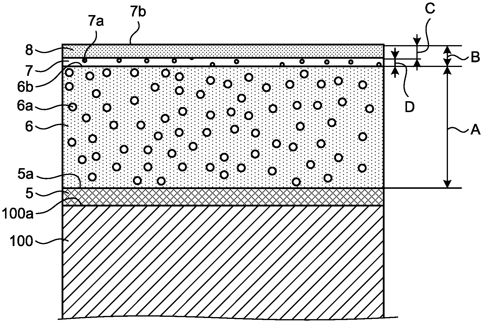
The TBC illustrated in FIG. 2 includes a metal bonding layer 5, a highly porous layer 6, and a dense layer 7 provided on the surface 100a of the heat-resistant base 100 in this order from the surface 100a.
The metal bonding layer 5 is made of a MCrAlY alloy (N represents a metallic element, such as Ni, Co, and Fe, or a combination of two or more of these elements), for example. The metal bonding layer 5 may be formed on the surface 100a of the heat-resistant base 100 by thermal spraying (low pressure plasma spraying (LPPS), high velocity oxygen fuel (HVOF), or atmospheric plasma spraying (APS)). The MCrAlY alloy is provided as the metal bonding layer 5 on the surface 100a of the heat-resistant base 100, thereby providing a corrosion-resistant function for the hear-resistant base 100 and a function as a binder for the highly porous layer 6.
The highly porous layer 6 is made of ceramic, such as YbSZ (ytterbia-stabilized zirconia having an addition ratio of Yb.sub.2O.sub.3 of equal to or higher than 0.01 wt % and equal to or lower than 17.00 wt %) or YSZ (yttria-stabilized zirconia), for example. The highly porous layer 6 may be formed on a surface 5a of the metal bonding layer 5 by APS using YbSZ powder or YSZ powder having a particle size distribution in which the particle diameter of a 10% cumulative particle size is equal to or larger than 30 .mu.m and equal to or smaller than 150 .mu.m. The highly porous layer 6 is a porous structure having a larger number of pores 6a and having a high heat-shielding property as a coating structure. "Having a larger number of pores" means that the pore ratio (vol %) is higher than that of the dense layer 7. The pore ratio of the highly porous layer 6 is equal to or higher than 1 vol % and equal to or lower than 30 vol % (preferably equal to or higher than 10 vol % and equal to or lower than 15 vol %). A layer thickness A of the highly porous layer 6 is equal to or larger than 0.3 mm and equal to or smaller than 1.0 mm. The Vickers hardness (conforming to JIS Z 2244, Vickers hardness test-Test method) of the highly porous layer 6 is equal to or higher than 800 Hv (preferably equal to or higher than 1000 Hv). The highly porous layer 6 has a vertically cracking structure having high durability on a surface 6b. The vertically cracking structure has vertical cracks within a range of equal to or larger than and equal to or smaller than 100% of the layer thickness A of the highly porous layer 6 thickness direction of the highly porous layer 6. The number of vertical cracks per unit length (1 mm) in the section of the highly porous layer 6 is equal to or larger than one and equal to or smaller than ten. With the highly porous layer 6, the TBC has heat-shielding and durability functions.
The dense layer 7 is made of YbSZ (ytterbia-stabilized zirconia having an addition ratio of Yb.sub.2O.sub.3 of equal to or higher than 0.01 wt % and equal to or lower than 17.00 wt %) or YSZ (yttria-stabilized zirconia), for example. The dense layer 7 may be formed on the surface 6b of the highly porous layer 6 by short-distance spraying (equal to or shorter than 100 mm) by APS using YbSZ powder or YSZ powder having a particle size distribution in which the average particle diameter is equal to or smaller than 20 .mu.m. The dense layer 7 may be formed on the surface 6b of the highly porous layer 6 by a known method (e.g., the cold spraying method or the aerosol deposition method) for enabling solidification and densification at normal temperature without sintering ceramic fine particles at high temperature. The dense layer 7 is a porous structure having a smaller number of pores 7a as a coating structure. "Having a smaller number of pores" means that the pore ratio (vol %) is lower than that of the highly porous layer 6. The pore ratio of the dense layer 7 is equal to or lower than 0.9 vol % (preferably lower than 0.5 vol %). A layer thickness B of the dense layer 7 is equal to or smaller than 0.05 mm. The Vickers hardness (conforming to JIS Z 2244, Vickers hardness test. Test method) of the dense layer 7 is equal to or higher than 800 Hv (preferably equal to or higher than 1000 Hv). With the dense layer 7, the TBC can have denseness on the outer layer, thereby increasing the penetration preventing property and having a corrosion-resistant function.
As described above, the TEC according to the present embodiment includes the metal bonding layer 5, the highly porous layer 6, and the dense layer 7. The metal bonding layer 5 is formed on the heat-resistant base 100. The highly porous layer 6 is formed on the metal bonding layer 5 and made of ceramic and has the pores 6a. The dense layer 7 is formed on the highly porous layer 6 and made of ceramic and has a pore ratio of equal to or lower than 0.9 vol % that is equal to or lower than that of the highly porous layer 6, a layer thickness of equal to or smaller than 0.05 mm, and a Vickers hardness of equal to or higher than 800 Hv.
This TBC can secure the heat-shielding property, for the heat-resistant base 100, in the highly porous layer 6 bonded to the heat-resistant base 100 with the metal bonding layer 5. With the dense layer 7 formed on the highly porous layer 6 and serving as a hard film having denseness in the pore ratio and the Vickers hardness, the TBC can secure the erosion resistance. Having denseness in the pore ratio of the dense layer 7 can prevent penetration of corrosive components and increase the corrosion resistance. As a result, the TBC can have higher durability in a high-temperature corrosive environment.
In the TBC according to the present embodiment, one of the highly porous layer 6 and the dense layer 7 is preferably made of a YbSZ (ytterbia-stabilized zirconia) material, and the other thereof is preferably made of a YSZ (yttria-stabilized zirconia) material. With the other of the highly porous layer 6 and the dense layer 7 made of the YSZ material, the TBC can be produced at a lower material cost than in a case where the YbSZ material is used. The YSZ material tends to have lower peeling resistance than that of the YbSZ material but has the penetration prevention performance corresponding to the corrosion-resistant function substantially equivalent to that of the YbSZ material.
In an example, the TBC has the structure illustrated in FIG. 2, and the highly porous layer 6 is made of the YbSZ material, and the dense layer 7 is made of the YSZ material. A high-temperature corrosion test was carried out on the TBC as follows: a corrosive component (Na.sub.2SO.sub.4) placed on a surface 7b of the dense layer 7 was melted in a high-temperature environment of 920 degrees C., and the state of penetration into the TBC was evaluated by an electron probe micro analyzer (EPMA). In the high-temperature corrosion test, no penetration of the corrosive component was found. In a TBC not including the dense layer 7, penetration of the corrosive component was found. Furthermore, a laser heat cycle test was carried out on the TBC subjected to the heat-temperature corrosion test to evaluate the peeling resistance. The results showed that the TBC had the peeling resistance equivalent to that of the TBC not including the dense layer 7.
In this TBC, one of the highly porous layer 6 and the dense layer 7 is made of the YSZ material, and the other thereof is made of the YbSZ material. Consequently, the TBC can significantly secure the heat-shielding property, for the heat-resistant base 100, in the highly porous layer 6. In addition, the TBC can secure the erosion resistance and significantly increase the corrosion resistance in the dense layer 7. As a result, the TBC can have higher durability in a high-temperature corrosive environment.
In the TBC according to the present embodiment, the highly porous layer 6 and the dense layer 7 are preferably made of the YbSZ material. With the highly porous layer 6 and the dense layer 7 both made of the YbSZ material, the TBC can have high heat-shielding, durability, and corrosion-resistant functions.
In another example, the TBC has the structure illustrated in FIG. 2, and the highly porous layer 6 and the dense layer 7 are made of the YbSZ material. A high-temperature corrosion test was carried out on the TBC as follows: a corrosive component (Na.sub.2SO.sub.4) placed on the surface 7b of the dense layer 7 was melted in a high-temperature environment of 920 degrees C., and the state of penetration into the TBC was evaluated by an EPMA. In the high-temperature corrosion test, no penetration of the corrosive component was found. In a TBC not including the dense layer 7, penetration of the corrosive component was found. Furthermore, a laser heat cycle test was carried out on the TBC subjected to the heat-temperature corrosion test to evaluate the peeling resistance. The results showed that the TBC had the peeling resistance equivalent to that of the TBC not including the dense layer 7.
In this TBC, the highly porous layer 6 and the dense layer 7 are made of the YbSZ material. Consequently, the TBC can more significantly secure the heat-shielding property, for the heat-resistant base 100, in the highly porous layer 6. In addition, the TBC can secure the erosion resistance and more significantly increase the corrosion resistance in the dense layer 7. As a result, the TBC can have higher durability in a high-temperature corrosive environment.
FIG. 3 is a schematic sectional diagram of another example of the TBC according to the present embodiment.
The TBC illustrated in FIG. 3 includes the metal bonding layer 5, the highly porous layer 6, the dense layer 7, and a molten layer 8 provided on the surface 100a of the heat-resistant base 100 in this order from the surface 100a.
Explanation of the metal bonding layer 5, the highly porous layer 6, and the dense layer 7 is omitted because they have the same structure as described above. The dense layer 7 is formed on the surface 6b of the highly porous layer 6 by short-distance spraying (equal to or shorter than 100 mm) by APS using YbSZ powder or YSZ powder having a particle size distribution in which the average particle diameter is equal to or smaller than 20 .mu.m.
The molten layer 8 is formed by melting, by high-speed laser scanning, the outer layer of the dense layer 7 formed by thermal spraying as described above. The high-speed laser scanning is performed so as to leave the dense layer 7 formed on the surface 6b of the highly porous layer 6. A layer thickness D of the dense layer 7 under the molten layer 8 is preferably equal to or larger than 0.01 mm so as not to deteriorate the advantageous effects described above. Because the layer thickness B of the dense layer 7 is equal to or smaller than 0.05 mm, a layer thickness C of the molten layer 8 is equal to or smaller than 0.04 mm (preferably equal to or smaller than 0.03 mm) considering the layer thickness D of the dense layer 7 under the molten layer 8.
The molten layer 8 is formed by melting the outer layer of the dense layer 7 made of the YSZ material or the YbSZ material and having a pore ratio of equal to or lower than 0.9 vol % (preferably lower than 0.5 vol %), and the melting makes the surface 7b of the dense layer 7 denser. Consequently, the TBC can further increase the corrosion resistance. As a result, the TBC can have higher durability in a high-temperature corrosive environment.
While the molten layer 8 may possibly have lower strength because of its high denseness, such a reduction in the strength can be suppressed by making the layer thickness D of the dense layer 7 under the molten layer 8 equal to or larger than 0.01 mm.
While the metal bonding layer 5 according to the embodiment is formed on the heat-resistant base 100 to bond the highly porous layer 6 to the heat-resistant base 100, the highly porous layer 6 may be bonded to the surface 100a of the heat-resistant base 100 without the metal bonding layer 5 depending on the material of the heat-resistant base 100. Consequently, the TBC may have such a structure as illustrated in FIGS. 2 and 3 but that does not include the metal bonding layer 5. Also in this case, the TBC can provide the advantageous effects equivalent to those of the structures illustrated in FIGS. 2 and 3.
REFERENCE SIGNS LIST
1 Compressor 11 Air intake port 12 Compressor casing 13 Compressor vane 14 Compressor blade 2 Combustor 21 Inner cylinder 22 Transition piece 23 Outer casing 24 Combustor casing 25 Air passage 3 Turbine 31 Turbine casing 32 Turbine vane 33 Turbine blade 34 Flue gas chamber 34a Flue gas diffuser 4 Turbine shaft 41, 42 Bearing 5 Metal bonding layer 5a Surface 6 Highly porous layer 6a Pore 6b Surface 7 Dense layer 7a Pore 7b Surface 8 Molten layer 10 Gas turbine 100 Heat-resistant base R Axis
* * * * *
D00000
D00001
D00002
XML
uspto.report is an independent third-party trademark research tool that is not affiliated, endorsed, or sponsored by the United States Patent and Trademark Office (USPTO) or any other governmental organization. The information provided by uspto.report is based on publicly available data at the time of writing and is intended for informational purposes only.
While we strive to provide accurate and up-to-date information, we do not guarantee the accuracy, completeness, reliability, or suitability of the information displayed on this site. The use of this site is at your own risk. Any reliance you place on such information is therefore strictly at your own risk.
All official trademark data, including owner information, should be verified by visiting the official USPTO website at www.uspto.gov. This site is not intended to replace professional legal advice and should not be used as a substitute for consulting with a legal professional who is knowledgeable about trademark law.