Rotary cutting tool with hone edges
Burton , et al. October 20, 2
U.S. patent number 10,807,172 [Application Number 16/108,530] was granted by the patent office on 2020-10-20 for rotary cutting tool with hone edges. This patent grant is currently assigned to Kyocera SGS Precision Tools, Inc.. The grantee listed for this patent is Kyocera SGS Precision Tools, Inc.. Invention is credited to Douglas P. Bonfiglio, Jeffery L. Burton, Jacob Rak.


View All Diagrams
| United States Patent | 10,807,172 |
| Burton , et al. | October 20, 2020 |
Rotary cutting tool with hone edges
Abstract
A rotary cutting tool includes a shaft having and outer surface and having a longitudinal axis, a plurality of helical flutes formed in the shaft about the longitudinal axis, a plurality of helical cutting edges formed at an interface with the outer surface and a respective helical flute about the longitudinal axis, and a plurality of end cutting edges located on an axial distal end of a cutting portion of the shaft, the end cutting edges being contiguous with a corresponding one of the plurality of helical cutting edges and forming a corner in the transition between each of the end cutting edges and the corresponding one of the plurality of helical cutting edges. A hone edge extends along a portion of each of the end cutting edges, the associated corner and a portion of the corresponding one of the plurality of helical cutting edges.
| Inventors: | Burton; Jeffery L. (Kent, OH), Bonfiglio; Douglas P. (Clinton, OH), Rak; Jacob (Munroe Falls, OH) | ||||||||||
|---|---|---|---|---|---|---|---|---|---|---|---|
| Applicant: |
|
||||||||||
| Assignee: | Kyocera SGS Precision Tools,
Inc. (Munroe Falls, OH) |
||||||||||
| Family ID: | 1000005124770 | ||||||||||
| Appl. No.: | 16/108,530 | ||||||||||
| Filed: | August 22, 2018 |
Prior Publication Data
| Document Identifier | Publication Date | |
|---|---|---|
| US 20190061023 A1 | Feb 28, 2019 | |
Related U.S. Patent Documents
| Application Number | Filing Date | Patent Number | Issue Date | ||
|---|---|---|---|---|---|
| 14741608 | Jun 17, 2015 | 10058934 | |||
| 62014085 | Jun 18, 2014 | ||||
| Current U.S. Class: | 1/1 |
| Current CPC Class: | B23C 5/10 (20130101); B24B 3/021 (20130101); B24B 3/06 (20130101); B23C 2210/126 (20130101); B23C 2210/0407 (20130101); B23C 2210/0485 (20130101); Y10T 407/1948 (20150115) |
| Current International Class: | B23C 5/10 (20060101); B24B 3/06 (20060101); B24B 3/02 (20060101) |
References Cited [Referenced By]
U.S. Patent Documents
| 3217382 | November 1965 | DeDobbelaere et al. |
| 3651602 | March 1972 | Hillier |
| 3798723 | March 1974 | Czopor et al. |
| 4963059 | October 1990 | Hiyama |
| 5425603 | June 1995 | Dutschke et al. |
| 5779399 | July 1998 | Kuberski |
| 5913644 | June 1999 | DeRoche et al. |
| 5947649 | September 1999 | Arai et al. |
| 6007276 | December 1999 | Wardell |
| 6132146 | October 2000 | Satran et al. |
| 6435780 | August 2002 | Flynn |
| 6846135 | January 2005 | Kuroda et al. |
| 6991409 | January 2006 | Noland |
| 6997651 | February 2006 | Kawai et al. |
| 7234224 | June 2007 | Naugler |
| 7306408 | December 2007 | Wells et al. |
| 7588396 | September 2009 | Flynn |
| 7789597 | September 2010 | Wells et al. |
| 8414228 | April 2013 | Wells et al. |
| 8939682 | January 2015 | Wells et al. |
| 9227253 | January 2016 | Swift et al. |
| 10058934 | August 2018 | Burton |
| 2002/0090273 | July 2002 | Serwa |
| 2004/0105729 | June 2004 | Giessler et al. |
| 2004/0120777 | June 2004 | Noland |
| 2005/0084341 | April 2005 | Long, II et al. |
| 2005/0105973 | May 2005 | MacArthur |
| 2008/0219782 | September 2008 | Flynn |
| 2012/0148352 | June 2012 | Miki et al. |
| 29 715 192 | Dec 1997 | DE | |||
| 10325600 | Jan 2005 | DE | |||
| 1971456 | Sep 2008 | EP | |||
| H06-129513 | Nov 1995 | JP | |||
| 2557189 | Dec 1997 | JP | |||
| 2005-118960 | May 2005 | JP | |||
Attorney, Agent or Firm: Vorys, Sater, Seymour and Pease LLP Guttman; Scott M.
Parent Case Text
CROSS-REFERENCE TO RELATED APPLICATIONS
This application claims priority to and the benefit of U.S. patent application Ser. No. 14/741,608 filed Jun. 17, 2015, and U.S. Provisional Patent Application No. 62/014,085 filed Jun. 18, 2014, the contents of which are hereby incorporated in their entirety.
Claims
What is claimed is:
1. A method of forming a rotary cutting tool comprising: providing a shaft having an outer surface and having a longitudinal axis forming a plurality of helical flutes in the shaft about the longitudinal axis defining a cutting portion, a remainder of the shaft defining a shank portion; forming a plurality of helical cutting edges at an interface with the outer surface and a respective helical flute about the longitudinal axis; forming a plurality of end cutting edges on an axial distal end of the cutting portion of the shaft, the end cutting edges being contiguous with a corresponding one of the plurality of helical cutting edges and forming a corner in a transition between each of the end cutting edges and the corresponding one of the plurality of helical cutting edges; and engaging one of the plurality of helical cutting edges, one of the plurality of end cutting edges associated therewith, and the corner transitioning therebetween with a filament brush to form a hone edge extending along a length of each of the one of the plurality of end cutting edges, the corresponding one of the plurality of helical cutting edges, and the corner transitioning therebetween.
2. The method of claim 1 further comprising, prior to forming the hone edges, securing the shaft in a chuck at the shank portion.
3. The method of claim 2 where the forming the hone edges includes rotating the shaft by the chuck.
4. The method of claim 1 where the filament brush is secured to a honing machine, and where in the forming the hone edges includes applying the filament brush of the honing machine to the length of the one of the plurality of helical cutting edges.
5. The method of claim 1 where the filament brush includes filaments flanged between two disks.
6. The Method of claim 1 where the filament brush is secured to a honing machine, and where in the forming the hone edges includes applying the filament brush of the honing machine to the length of the one of the plurality of end cutting edges.
7. The method of claim 6 where the honing machine includes filaments flanged between two disks.
8. The method of claim 1 where the hone edges are varying hone edges.
9. The method of claim 8 where the varying hone edges increase from the associated helical cutting edge toward the end cutting edge associated therewith.
10. The method of claim 8 where there is increased honing on the corners as compared to the helical cutting edges.
11. The method of claim 1 where the forming hone edges is performed by a CNC machine.
12. The method of claim 1 where the filament brush engages one of the plurality of helical cutting edges with a varying load along the length of the one of the plurality of helical cutting edges.
13. The method of claim 1 where the filament brush engages one of the plurality of end cutting edges with a varying load along the length of the one of the plurality of end cutting edges.
14. The method of claim 1 where the filament brush engages one of the plurality of helical cutting edges and the one of the plurality of end cutting edges with a varying load along both the length of the one of the plurality of helical cutting edges and the length of the one of the plurality of end cutting edges.
15. The method of claim 4 where the filament brush of the honing machine is applied to the length of the one of the plurality of helical cutting edges with a varying load.
16. The method of claim 6 where the filament brush of the honing machine is applied to the length of the one of the plurality of end cutting edges with a varying load.
17. The method of claim 1 where the filament brush is a diamond impregnated fiber brush.
18. The method of claim 4 further comprising: pivoting the filament brush of the hone machine 90 degrees about the corner; and where forming the hone edges includes applying the filament brush of the honing machine to the length of the one of the plurality of end cutting edges.
19. The method of claim 1 where the hone edge extending along the length of each of the one of the plurality end cutting edges, the corresponding one of the plurality of helical cutting edges, and the corner transitioning therebetween includes an edge radius, where the edge radius is variable along the hone edge length through the helical cutting edge, the corner, and the end cutting edge and where an axial angle and a radial angle of the contiguous hone edge are geometrically positive relative to rotating the shaft in a clock-wise rotational direction about the longitudinal axis.
Description
BACKGROUND
This relates in general to rotary cutting tools. One type of known rotary cutting tool is an end mill, see FIG. 1. End mills typically consist of one or more flutes including a deep helical groove that runs up the cylindrical outer surface of the milling bit. In operation, associated cutting edges may cut a work piece material; together, the flutes and cutting edges--by virtue of rotation of the milling bit--cut away and remove pieces of the work piece in a manner that creates the desired form.
One example of a known rotary cutting tool is the Z-Carb.RTM. end mill manufactured under U.S. Pat. No. 4,963,059. The U.S. Pat. No. 4,963,059 disclosed an end mill having a plurality of paired helical flutes forming an even number of helical peripheral cutting edges equally spaced circumferentially in one plane wherein the peripheral cutting edges are formed as a plurality of pairs of diametrically opposite cutting edges having the same helix angle and thereby being symmetrical with respect to the axis of the body.
End mills peripheral cutting edges remove the bulk of material, but the chip forming process starts near the corner of each edge. Repeated impact in this region can be particularly stressful to an end mill and some form of strengthening is desired.
The corners of carbide end mills can be one the weakest area of such a tool, see FIG. 2. The corners of end mills also tend to be the most vulnerable area, being most susceptible to the onset of chip damage, see FIG. 3. The increased operating parameters brought about by the ever increasing use of high performance end mill designs has furthered this concern. Several methods that have been explored and implemented to protecting these corners includes a series of grinds, which may be costly and/or difficult to control during manufacturing.
One know simple method of corner strengthening includes a chamfer. Other more complicated methods includes a corner radius, see FIGS. 4 and 5. A corner radius will reduce stresses in the areas where applied. However this method is not sufficient protection for milling most materials. Additional protection methods include a faced hook, see FIGS. 6 and 7 at FH, in which the gashing at the end of the tool is carried out to the corners. This may significantly increase the strength by making the geometry more negative, i.e. blunt; however the tradeoff is lost shearing capability and less efficient cutting.
Further methods include the above combined with various gashing methods. A blending grind may be added to the corner radius to further improve functionality and smooth the surface transition. A compromise is to blend the end gashing into the fluting to subdue the faced hook. This is commonly called a "B-Rad" (blend radius), or blend gashing. The downside is that this blend is difficult to manufacture and some of the negative geometry still exists, see FIGS. 8 and 9 at BR.
Additionally, portions of all of the above tools still tend to be subject to chipping or other generally undesired damage.
SUMMARY
This relates more specifically to a rotary cutting tool including a shaft having an outer surface and having a longitudinal axis with a plurality of helical flutes formed in the shaft about the longitudinal axis and a plurality of helical cutting edges formed at an interface of a respective the helical flutes with the outer surface about the longitudinal axis
One embodiment includes treating the cutting edges as an improved method of reducing corner damage and improving performance of solid carbide end mills. One such treatment includes honing at least a portion of the cutting edges. Honing is the action of rounding an otherwise sharp cutting edge so as to remove keenness and thereby toughen the edge for improved chip resistance. One treatment may include a consistent hone, which encompasses the radial edges, in part of around the entire periphery, but it is consistent in size, with virtually no variation.
The treatment may include varying hone, varying the hone size according to location along the cutting edge or around the periphery. In one example, there is hone applied to the radial edges and a relatively heavier hone applied to areas requiring additional toughness, such as the corner radii.
It is expected that this varying hone will result in less corner chipping. In one instance, the application of the varying hone may be achieved through the use of a computer controlled brush honing machine, which provides the control required to change hone size. Such a machine may be further enhanced by flanging the normally loose filament brush so as to better localize the filament, resulting in a more precise honing process.
Testing of the varying hone shows that not only are the corner radii sufficiently more protected, cutting force and torque are reduced, and radial edge condition is improved, as compared to other methods for reducing corner chipping.
In at least one embodiment, a rotary cutting tool includes a shaft having and outer surface and having a longitudinal axis, a plurality of helical flutes formed in the shaft about the longitudinal axis, a plurality of helical cutting edges formed at an interface with the outer surface and a respective helical flute about the longitudinal axis, and a plurality of end cutting edges located on an axial distal end of a cutting portion of the shaft, the end cutting edges being contiguous with a corresponding one of the plurality of helical cutting edges and forming a corner in the transition between each of the end cutting edges and the corresponding one of the plurality of helical cutting edges. A hone edge extends along a portion of each of the end cutting edges, the associated corner and a portion of the corresponding one of the plurality of helical cutting edges.
Various aspects will become apparent to those skilled in the art from the following detailed description and the accompanying drawings.
BRIEF DESCRIPTION OF THE DRAWINGS
FIG. 1 is a side view of a known end mill.
FIG. 2 is an enlarged portion of the end mill of FIG. 1.
FIG. 3 is a view similar to FIG. 2 except showing the end will after significant wear. and show new and used corners.
FIG. 4 is a tangential view of a portion of an end mill with corner radius.
FIG. 5 is a side of the portion of the end mill of FIG. 4.
FIG. 6 is a tangential view of a portion of an end mill with faced hook.
FIG. 7 is a side of the portion of the end mill of FIG. 4.
FIG. 8 is a tangential view of a portion of an end mill with B-Rad.
FIG. 9 is a side of the portion of the end mill of FIG. 4.
FIG. 10 is an enlarged front view of a portion of an end mill with hone edges.
FIG. 11 is a further enlarged portion of FIG. 10.
FIG. 12 is a tangential view the end mill of FIG. 10.
FIG. 13 is a side view of the end mill of FIG. 10.
FIG. 14 is an enlarged perspective view of the hone edge of the end mill of FIG. 10.
FIG. 15 is a schematic illustration of a first hone edge.
FIG. 16 is a schematic illustration of a second hone edge.
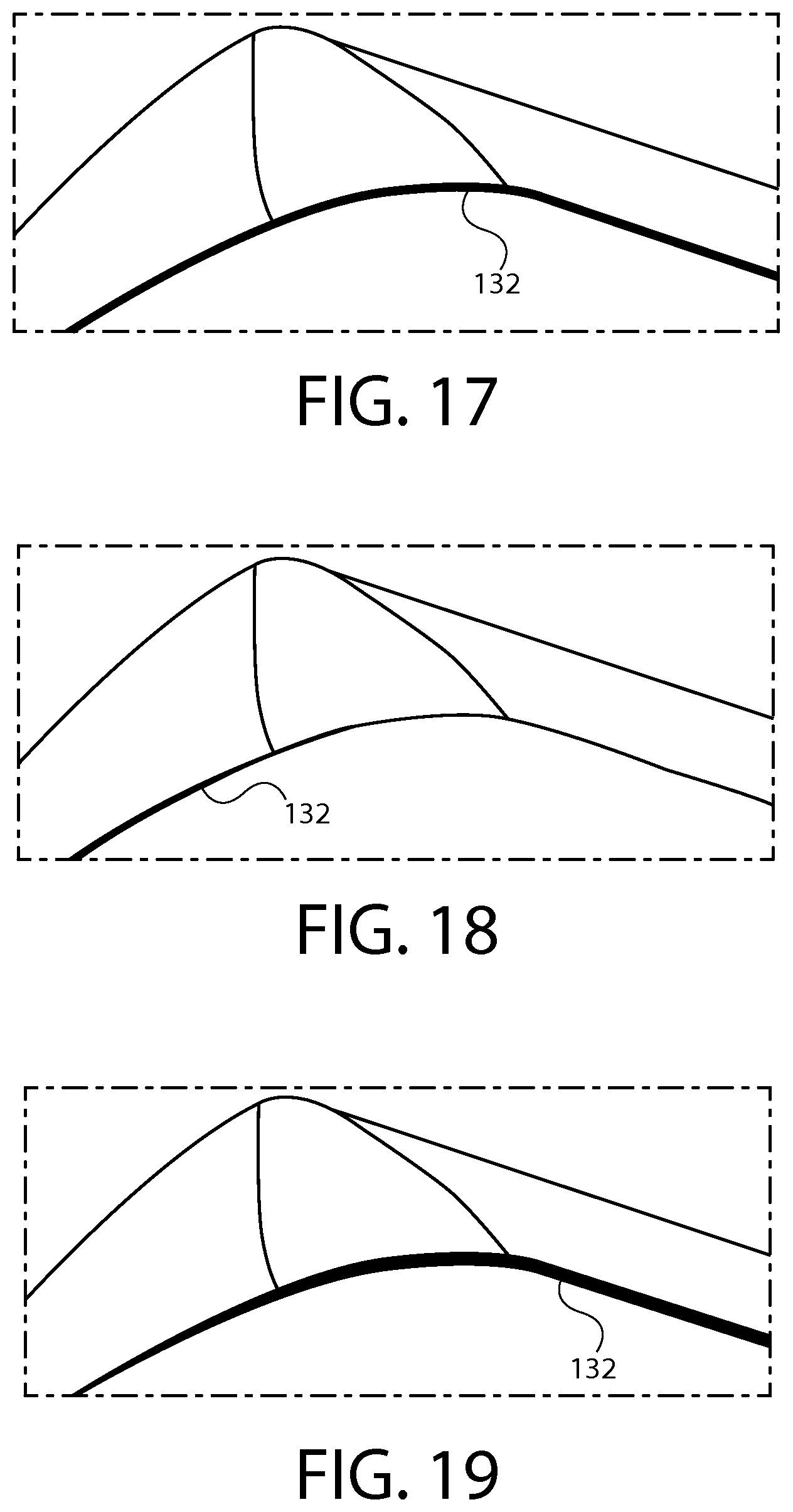
FIG. 17 is a schematic illustration of a third hone edge.
FIG. 18 is a schematic illustration of a fourth hone edge.
FIG. 19 is a schematic illustration of a fifth hone edge.
FIG. 20 is an enlarged view of a cutting edge of a conventional end mill after use.
FIG. 21 is an enlarged view of a cutting edge of an end mill with hone edge after use.
FIG. 22 is a front view of a portion of a CNC machine including a chuck holding a shaft.
FIG. 23 is a front view of another portion of the CNC machine of FIG. 22 including a machine brush.
FIG. 24 is a perspective view of the brush of FIG. 23.
FIG. 25 is another perspective view of the CNC machine of FIGS. 22-24 showing the machine in operation.
FIG. 26 is a further perspective view of the CNC machine of FIGS. 22-24 showing the machine in further operation.
FIG. 27 shows an end mill with B-Rad.
FIG. 28 shows an end mill with hone edge.
DETAILED DESCRIPTION
There is shown in FIGS. 10-14, 21 and 28 an end mill rotary cutting tool 110. The tool 110 includes a shaft 112 having and an outer surface 114 and having a longitudinal axis X. The shaft 112 includes a shank portion 116, see FIG. 22, and cutting portion 118. A plurality of helical flutes 120 are formed in the shaft 112 in the cutting portion 118 about the longitudinal axis X.
A plurality of helical cutting edges 122 are formed at an interface with the outer surface 114 and a respective helical flute 120 about the longitudinal axis X. A plurality of end cutting edges 124 are located on an axial distal end 126 of the cutting portion 118 of the shaft 112. The end cutting edges 124 are contiguous with a corresponding one of the plurality of helical cutting edges 122 and form a corner 128 in the transition between each of the end cutting edges 124 and the corresponding one of the plurality of helical cutting edges 122.
A hone edge 130 extends along a portion of each of the end cutting edges 124, the associated corner 128 and a portion of the corresponding one of the plurality of helical cutting edges 122.
The hone edges 130 may all be varying hone edges, that is to say that the amount of honing may vary along the length of the edge. The varying hone edges 130 may, for example, increase from the associated helical cutting edge 122 toward the associated end cutting edge 124. There may be increased honing on the corners 128 as compared to the helical cutting edges 122 or as compared to the end cutting edges 124 or both. The hone edges 130 may be formed to all be geometrically positive.
The end mill of Claim 2 where the helix angle of the helical flutes varies along the longitudinal axis.
The rake angle of the helical cutting edges 122 may vary along the longitudinal axis X.
There is illustrated in FIGS. 15-19 a variety of hone edge with the thickness of the hone line 132 indicating the amount of honing by location.
In one embodiment, edges are rounded with a diamond impregnated fiber brush. Upon testing, see the method of corner strengthening has produced significant results. The corner radius stronger, as compared to other methods, and cutting force and torque were lower, and overall tool condition was better.
This method may include that the treatment size would not be consistent over the entire edge length. For example, it may vary so as to provide protection according to the load associated with a specific location on an end mill, or vary in any other way as desired. As an example, the axial edges may receive 0.001-0.002 (inch) radius, transitioning around the corner radius to 0.0003-0.0005 (inch) on the radial edges.
Listed are some of the benefits discovered provided by varying edge treatment as compared to other edge treatments: reduction of maximum force by 13.8% and torque by 11.5%, improvement of chip resistance at the corners over conventional protection methods, and improvement of chip resistance along the radial cutting edge.
In one embodiment this may be combine with varying helix and/or varying rake to create a tool where the combination of two or three work together. It is expected that the varying rake/varying helix will reduce vibration, while the varying hone may be able to withstand more vibration. It is expected that when combined these features will create a highly chip resistant design.
Illustrated is a test that compares a standard Z-Carb AP manufactured with a B-Rad, see FIGS. 20 and 27, to the identical product manufactured without a B-Rad, but with an axial edge treatment (hone) of 0.001 (inch), see FIGS. 21 and 28.
Profile cuts were made in 4140 and 316 stainless at Tool Wizard parameters. Parameters for Test 085-09 were duplicated, which was a test that had shown the comparison between a B-Rad and a conventional unprotected corner radius. In the 4140 profile test, the stockroom sample (T1) showed micro-chipping, as typically observed during a coating test. T2, without the B-Rad but with the axial hone, did not show this edge condition. Neither tool showed any notable corner radius area damage. In Test 2, profile milling in 316 stainless, the stockroom sample (T3) showed edge chipping which was not exhibited by T4, the non-B-Rad/axial honed tool. Neither tool showed any corner damage. Test 3 involved profile milling in 15-5 PH stainless and after milling 1600 inches both tools (T5 and T6) had identical wear and chipping and no corner radius area damage. Test 4 used the load cell to determine tool load while plunging. Each tool was plunged into the 4140 workpiece three times and the forces measured, recorded and averaged. Tool 8 with no B-Rad and the axial hone averaged 14 percent less maximum Z-axis force and 12 percent less maximum torque than the stockroom sample (T7).
In summary, in these tests, the stockroom samples showed edge damage equal to or worse than the axial honed tools, as well as generating more Z-axis force and torque while plunging. Overall, the preliminary results suggest the axial edge treatment is not detrimental to performance, and is likely beneficial to reduce corner damage as compared to the non-axial honed tools.
Below are Tables representing Test 1-Test 4 that illustrate four tests of stock sample compared to a honed sample.
TABLE-US-00001 ToolWizardparameters(Test1) MACHINE TOOLHOLDER COOLANT 4140alloysteel28HRc HaasVM3 TechniksER-32short S-373 SPEED FEED RADIALWIDTH AXIALDEPTH 2,865rpm/375sfm 26.24ipm/.00229ipt .250''(50%D) .500''(D) TOOL TYPE TIRIN NO. DESCRIPTION MACHINE USAGE INSPECTION . . . NOTES 1 ZAP1C05000_030TXstockroom .0003'' 640'' Varyingmicrochippingoncuttingedgesandcornerradii. sample 2 TestsamplewithoutB-Rad; .001''axial .0004'' 640'' Evenandconsistentoncuttingedgesandcornerradii hone,
TABLE-US-00002 ToolWizardparameters(Test2) WORKPIECE MACHINE TOOLHOLDER COOLANT 316stainless HaasVM3 TechniksER-32short S-373 SPEED FEED RADIALWIDTH AXIALDEPTH 3,025rpm/396sfm 21.78ipm/.0018ipt .250'' (50%D) .400''(80%D) TOOL TYPE TIRIN NO. DESCRIPTION MACHINE USAGE INSPECTION . . . NOTES 3 ZAP1C05000_030TXstockroom .0003'' 640'' Varyingedgedamagewithchipping.0044''to.007''onprimary sample Corners/B-Radintact 4 TestsamplewithoutB-Rad; .001''axial .0002'' 640'' .0008''edgewear, evenandconsistentoncuttingedgesandcornerradii hone,
TABLE-US-00003 Parametersfromtest085-09(Test3) WORKPIECE MACHINE TOOLHOLDER COOLANT 15-5 PHstainless HaasVM3 TechniksER-32short S-373 35/37HRc SPEED FEED RADIALWIDTH AXIALDEPTH 2,180rpm/285sfm 17.0ipm/.0019ipt .250'' .125'' TOOL TYPE TIRIN NO. DESCRIPTION MACHINE USAGE INSPECTION . . . NOTES 5 ZAP1C05000_030TXstockroom .0002'' 1120'' .0025''wear, nottooldamage sample 1600'' .0032''wear, eachflutehasasmallchiponedge. Nocornerareadamage 6 TestsamplewithoutB-Rad; .001''axial .0004'' 1120'' .0025''wear, notooldamage. hone, 1600'' .0033''wear, eachflutehasasmallchiponedge. Nocornerarea damage.
TABLE-US-00004 Plungeinloadcell(Test4) WORKPIECE MACHINE TOOLHOLDER COOLANT 4140alloysteel28HRc HaasVM3 TechniksER-32short S-373 SPEED FEED RADIALWIDTH AXIALDEPTH 2,865rpm/375sfm 13.0ipm/.0045ipr .500''(D) .050'' TOOL TYPE TIRIN NO. DESCRIPTION MACHINE USAGE INSPECTION . . . NOTES 7 ZAP1C05000_030TX stockroom .0003'' 3plunges 328.14lbsaveragemaximumZ-axisload.69.1averageinlbstorque sample 8 TestsamplewithoutB-Rad; .001''axial .0003'' 3plunges 282.89lbsaveragemaximumZ-axisload.61.1averageinlbstorque hone, Comments: Tool8hadapproximately14%lessaverageZ-axisloadand12%lessaveragetorquerequir- ement(maxiumuns)
Below are Tables Tool 7 and Tool 8 that give the parameters for the stock sample and honed sample, Plunges 1-3.
TABLE-US-00005 Tool7stockroomsample Plunge1 Plunge2 Plunge3 UNITS .fwdarw. "lbs" UNITS .fwdarw. "lbs" UNITS .fwdarw. "lbs" MEAN .fwdarw. 265.72 MEAN .fwdarw. 265.85 MEAN .fwdarw. 275.03 STD DEV. .fwdarw. 50.05 STD DEV. .fwdarw. 54.32 STD DEV. .fwdarw. 66.14 MINIMUM .fwdarw. 104.80 MINIMUM .fwdarw. 117.05 MINIMUM .fwdarw. 70.62 MEDIAN .fwdarw. 282.62 MEDIAN .fwdarw. 284.24 MEDIAN .fwdarw. 291.65 MAXIMUM .fwdarw. 315.67 MAXIMUM .fwdarw. 315.67 MAXIMUM .fwdarw. 353.08 UNITS .fwdarw. "inlb" UNITS .fwdarw. "inlb" UNITS .fwdarw. "inlb" MEAN .fwdarw. 52.211 MEAN .fwdarw. 50.895 MEAN .fwdarw. 50.236 STD DEV. .fwdarw. 11.651 STD DEV. .fwdarw. 15.633 STD DEV. .fwdarw. 15.741 MINIMUM .fwdarw. 19.342 MINIMUM .fwdarw. 5.120 MINIMUM .fwdarw. 6.827 MEDIAN .fwdarw. 54.233 MEDIAN .fwdarw. 54.327 MEDIAN .fwdarw. 52.716 MAXIMUM .fwdarw. 66.274 MAXIMUM .fwdarw. 71.204 MAXIMUM .fwdarw. 69.687
TABLE-US-00006 Tool8withoutB-Radand.001axialedgeprep/hone Plunge1 Plunge2 Plunge3 UNITS .fwdarw. "lbs" UNITS .fwdarw. "lbs" UNITS .fwdarw. "lbs" MEAN .fwdarw. 238.00 MEAN .fwdarw. 244.21 MEAN .fwdarw. 248.13 STD DEV. .fwdarw. 15.09 STD DEV. .fwdarw. 20.69 STD DEV. .fwdarw. 38.18 MINIMUM .fwdarw. 205.42 MINIMUM .fwdarw. 184.60 MINIMUM .fwdarw. 119.71 MEDIAN .fwdarw. 239.90 MEDIAN .fwdarw. 247.55 MEDIAN .fwdarw. 253.56 MAXIMUM .fwdarw. 261.21 MAXIMUM .fwdarw. 267.55 MAXIMUM .fwdarw. 319.92 UNITS .fwdarw. "inlb" UNITS .fwdarw. "inlb" UNITS .fwdarw. "inlb" MEAN .fwdarw. 46.779 MEAN .fwdarw. 47.885 MEAN .fwdarw. 48.260 STD DEV. .fwdarw. 7.386 STD DEV. .fwdarw. 7.835 STD DEV. .fwdarw. 13.354 MINIMUM .fwdarw. 22.394 MINIMUM .fwdarw. 20.964 MINIMUM .fwdarw. 7.433 MEDIAN .fwdarw. 49.076 MEDIAN .fwdarw. 49.409 MEDIAN .fwdarw. 48.028 MAXIMUM .fwdarw. 55.175 MAXIMUM .fwdarw. 57.938 MAXIMUM .fwdarw. 70.136
The developed method addresses the corner strength issue while also maintaining efficient shearing capability. By utilizing a CNC brush honing machine, method has been crafted to utilize brush wheel of the hone machine to produce a relatively wider, heavier hone at the axial end of the tool which diminishes in size as it proceeds down the radial side of the flutes.
By eliminating the faced hook and B-Rad, the shearing capability is improved and by adding the variable hone the corners are protected.
One method of forming a rotary cutting tool includes the steps of: providing a shaft having and outer surface and having a longitudinal axis; forming a plurality of helical flutes in the shaft about the longitudinal axis defining a cutting portion, the remainder of the shaft defining a shank portion; forming a plurality of helical cutting edges at an interface with the outer surface and a respective helical flute about the longitudinal axis; forming a plurality of end cutting edges on an axial distal end of cutting portion of the shaft, the end cutting edges being contiguous with a corresponding one of the plurality of helical cutting edges and forming a corner in the transition between each of the end cutting edges and the corresponding one of the plurality of helical cutting edges; and forming a hone edge extending along a portion of each of the end cutting edges, the associated corner and a portion of the corresponding one of the plurality of helical cutting edges.
Referring to FIGS. 22-26, the shaft may be secured in chuck at the shank portion and then rotated. A machining brush may be provided and applied to the helical cutting edges, the corners, and/or the end cutting edges to form hone edges, such as varying hone edges. The brush may include filaments flanged between two disks. This may be performed by a CNC machine.
While principles and modes of operation have been explained and illustrated with regard to particular embodiments, it must be understood, however, that this may be practiced otherwise than as specifically explained and illustrated without departing from its spirit or scope.
* * * * *
D00000
D00001
D00002
D00003
D00004
D00005
D00006
D00007
D00008
D00009
D00010
D00011
D00012

D00013

XML
uspto.report is an independent third-party trademark research tool that is not affiliated, endorsed, or sponsored by the United States Patent and Trademark Office (USPTO) or any other governmental organization. The information provided by uspto.report is based on publicly available data at the time of writing and is intended for informational purposes only.
While we strive to provide accurate and up-to-date information, we do not guarantee the accuracy, completeness, reliability, or suitability of the information displayed on this site. The use of this site is at your own risk. Any reliance you place on such information is therefore strictly at your own risk.
All official trademark data, including owner information, should be verified by visiting the official USPTO website at www.uspto.gov. This site is not intended to replace professional legal advice and should not be used as a substitute for consulting with a legal professional who is knowledgeable about trademark law.