Ball with sensor
Lin October 20, 2
U.S. patent number 10,806,972 [Application Number 16/693,215] was granted by the patent office on 2020-10-20 for ball with sensor. The grantee listed for this patent is Yi Ching Lin. Invention is credited to Yi Ching Lin.


| United States Patent | 10,806,972 |
| Lin | October 20, 2020 |
Ball with sensor
Abstract
A ball has a hollow ball, a sensor, and a sensor assembling structure. The hollow ball is hollow, is inflatable, and has an inner peripheral surface. The sensor is disposed at a central position inside the hollow ball. The sensor assembling structure has an installation assembly and a thermal insulation coat. The installation assembly has multiple connecting members. Each one of the multiple connecting members is made of a thermal insulation material and is connected to the inner peripheral surface of the hollow ball. The thermal insulation coat is connected to the multiple connecting members and is wrapped around the sensor for thermally insulating the sensor. The sensor assembling structure retains the sensor at the central position inside the hollow ball for collecting data and improving efficiency during training of athletes.
| Inventors: | Lin; Yi Ching (Kaohsiung, TW) | ||||||||||
|---|---|---|---|---|---|---|---|---|---|---|---|
| Applicant: |
|
||||||||||
| Family ID: | 69780798 | ||||||||||
| Appl. No.: | 16/693,215 | ||||||||||
| Filed: | November 22, 2019 |
Foreign Application Priority Data
| Sep 23, 2019 [TW] | 108212518 U | |||
| Current U.S. Class: | 1/1 |
| Current CPC Class: | A63B 43/004 (20130101); A63B 41/00 (20130101); A63B 2220/30 (20130101); A63B 24/0062 (20130101); A63B 2220/833 (20130101); A63B 2209/00 (20130101) |
| Current International Class: | A63B 43/00 (20060101); A63B 41/00 (20060101) |
References Cited [Referenced By]
U.S. Patent Documents
| 3709491 | January 1973 | Minchin |
| 5725445 | March 1998 | Kennedy |
| 6251035 | June 2001 | Fa |
| 6537125 | March 2003 | Motosko, III |
| 7614959 | November 2009 | Gentile |
| 10523053 | December 2019 | Munson |
| 2003/0224885 | December 2003 | Leal |
| 2005/0288134 | December 2005 | Smith |
| 2006/0063622 | March 2006 | Nurnberg |
| 2008/0274844 | November 2008 | Ward |
| 2009/0111619 | April 2009 | Kobayashi |
| 2010/0069181 | March 2010 | Lin |
| 2010/0130314 | May 2010 | Von Der Gruen |
| 2011/0077112 | March 2011 | Erario |
| 2011/0118062 | May 2011 | Krysiak |
| 2014/0194232 | July 2014 | Krysiak |
| 2015/0182810 | July 2015 | Thurman |
| 2015/0224369 | August 2015 | Ahn |
| 2016/0107046 | April 2016 | Krysiak |
| 2017/0246513 | August 2017 | Fang |
| 2018/0147455 | May 2018 | Lee |
| 2018/0154222 | June 2018 | Thurman |
| 2018/0200582 | July 2018 | Thurman |
| 2018/0200583 | July 2018 | Thurman |
| 2353666 | Aug 2011 | EP | |||
| 3010910 | Mar 2015 | FR | |||
| WO-2008080626 | Jul 2008 | WO | |||
Attorney, Agent or Firm: Hershkovitz & Associates, PLLC Hershkovitz; Abe
Claims
What is claimed is:
1. A ball comprising: a hollow ball being hollow, being inflatable, and having an inner peripheral surface; a sensor disposed at a central position inside the hollow ball; and a sensor assembling structure having an installation assembly having multiple connecting members; each one of the multiple connecting members made of a thermal insulation material, being elongated, and having a first end and a second end opposite the first end of the connecting member, and the second ends of the multiple connecting members connected to the inner peripheral surface of the hollow ball; and a thermal insulation coat connected to the first end of each one of the multiple connecting members and wrapped around the sensor for thermally insulating the sensor; and multiple fastening joints protruding from the inner peripheral surface of the hollow ball, and respectively attached to the second ends of the multiple connecting members; wherein the second ends of the multiple connecting members are respectively mounted around the multiple fastening joints and are tightened by threads.
2. The ball as claimed in claim 1, wherein the thermal insulation coat is made of glass fiber.
3. A ball comprising: a hollow ball being hollow, being inflatable, and having an inner peripheral surface; a sensor disposed at a central position inside the hollow ball; and a sensor assembling structure having an installation assembly having multiple connecting members; each one of the multiple connecting members made of a thermal insulation material, being elongated, and having a middle section and two opposite ends connected to the inner peripheral surface of the hollow ball; and the middle sections of the multiple connecting members intersected with each other; and a thermal insulation coat connected to the multiple connecting members and wrapped around the sensor for thermally insulating the sensor; and multiple fastening joints protruding from the inner peripheral surface of the hollow ball; the two opposite ends of each one of the multiple connecting members respectively mounted to two corresponding ones of the multiple fastening joints and connected to the inner peripheral surface of the hollow ball via the two corresponding fastening joints, wherein the two opposite ends of each one of the multiple connecting members are respectively mounted around two corresponding ones of the multiple fastening joints and are respectively tightened by threads.
4. The ball as claimed in claim 3, wherein the thermal insulation coat is made of polytetrafluoroethylene.
5. The ball as claimed in claim 3, wherein each one of the multiple connecting members has an inserting hole defined through the middle section of the connecting member for the other connecting members to be mounted through.
6. The ball as claimed in claim 3, wherein the sensor and the thermal insulation coat wrapped around the sensor are disposed within one of the multiple connecting members; and the middle sections of the multiple connecting members are tightened by threads to keep the sensor and the thermal insulation coat disposed at the central position inside the hollow ball.
Description
BACKGROUND OF THE INVENTION
1. Field of the Invention
The present invention relates to a ball with a sensor, and more particularly to a ball with a hollow ball and a sensor disposed at a central position inside the hollow ball.
2. Description of Related Art
In order to detect pitching velocities or contact points during baseball drills, a coach has to stand close to a pitcher or a hitter and to hold a detecting device to collect data of pitching velocities or contact points. The coach standing next to the pitcher or the hitter is subject to risk of being hit by a flying baseball and getting hurt.
For avoiding injuring the coach, a baseball with detecting function has been invented and is commercially available. The baseball is equipped with a sensor disposed within the baseball. The sensor is linked to a mobile device prior to a baseball drill. Therefore, the sensor can collect data and transmit the collected data to the mobile device. The baseball with detecting function lowers the risk of injuring the coach.
The baseball is solid inside, so the sensor can be easily embedded at a central position inside the baseball without altering the position of the center of mass of the baseball. However, a hollow athletic ball such as a basketball, a volleyball, or a soccer ball has a bladder and is inflatable. The sensor is difficult to be located at a central position inside the hollow athletic ball without altering the position of the center of mass of the hollow athletic ball and changing the flying path of the hollow athletic ball. Moreover, the bladder of the hollow athletic ball has to be thermally treated during manufacturing. The heat provided by a thermal treatment may damage the sensor inside the hollow athletic ball.
Therefore, to maintain the sensor disposed at the central position of the hollow athletic ball and to prevent the sensor from being damaged by heat generated by thermal treatment, the manufacturers of athletic balls have endeavored to seek improvement of means for assembling the sensor inside the hollow athletic ball.
To improve the conventional hollow athletic ball with a sensor, the present invention provides a ball with a sensor to mitigate or obviate the aforementioned problems.
SUMMARY OF THE INVENTION
The main objective of the present invention is to provide a ball with a sensor that keeps the sensor disposed at a central position inside the ball and keeps the sensor from being damaged by heat generated by thermal treatment.
The ball with a sensor comprises a hollow ball, a sensor, and a sensor assembling structure. The hollow ball is hollow, is inflatable, and has an inner peripheral surface. The sensor is disposed at a central position inside the hollow ball. The sensor assembling structure has an installation assembly and a thermal insulation coat. The installation assembly has multiple connecting members. Each one of the multiple connecting members is made of a thermal insulation material and is connected to the inner peripheral surface of the hollow ball. The thermal insulation coat is connected to the multiple connecting members and is wrapped around the sensor for thermally insulating the sensor. The sensor assembling structure retains the sensor at the central position inside the hollow ball for collecting data and improving efficiency during training of athletes.
Other objects, advantages, and novel features of the invention will become more apparent from the following detailed description when taken in conjunction with the accompanying drawings.
BRIEF DESCRIPTION OF THE DRAWINGS
FIG. 1 is a side view in partial section of a first embodiment of a ball with a sensor in accordance with the present invention;
FIG. 2 is a side view in partial section of a second embodiment of a ball with a sensor in accordance with the present invention;
FIG. 3 is a side view in partial section of a third embodiment of a ball with a sensor in accordance with the present invention;
FIG. 4 is a partially enlarged side view in partial section of the ball in FIG. 3;
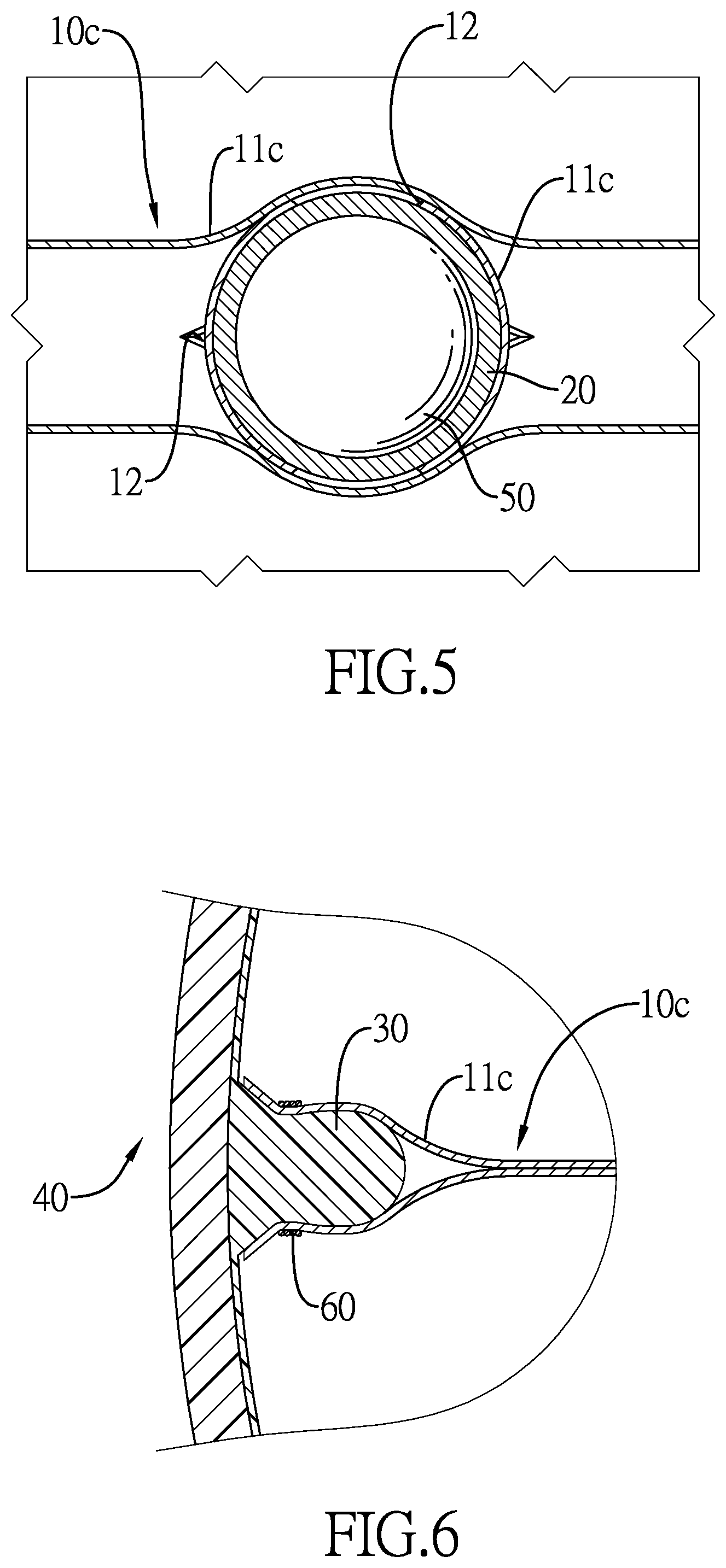
FIG. 5 is a partially enlarged cross sectional side view of the ball along line 5-5 in FIG. 4; and
FIG. 6 is a partially enlarged cross sectional side view of the ball along line 6-6 in FIG. 4.
DETAILED DESCRIPTION OF PREFERRED EMBODIMENTS
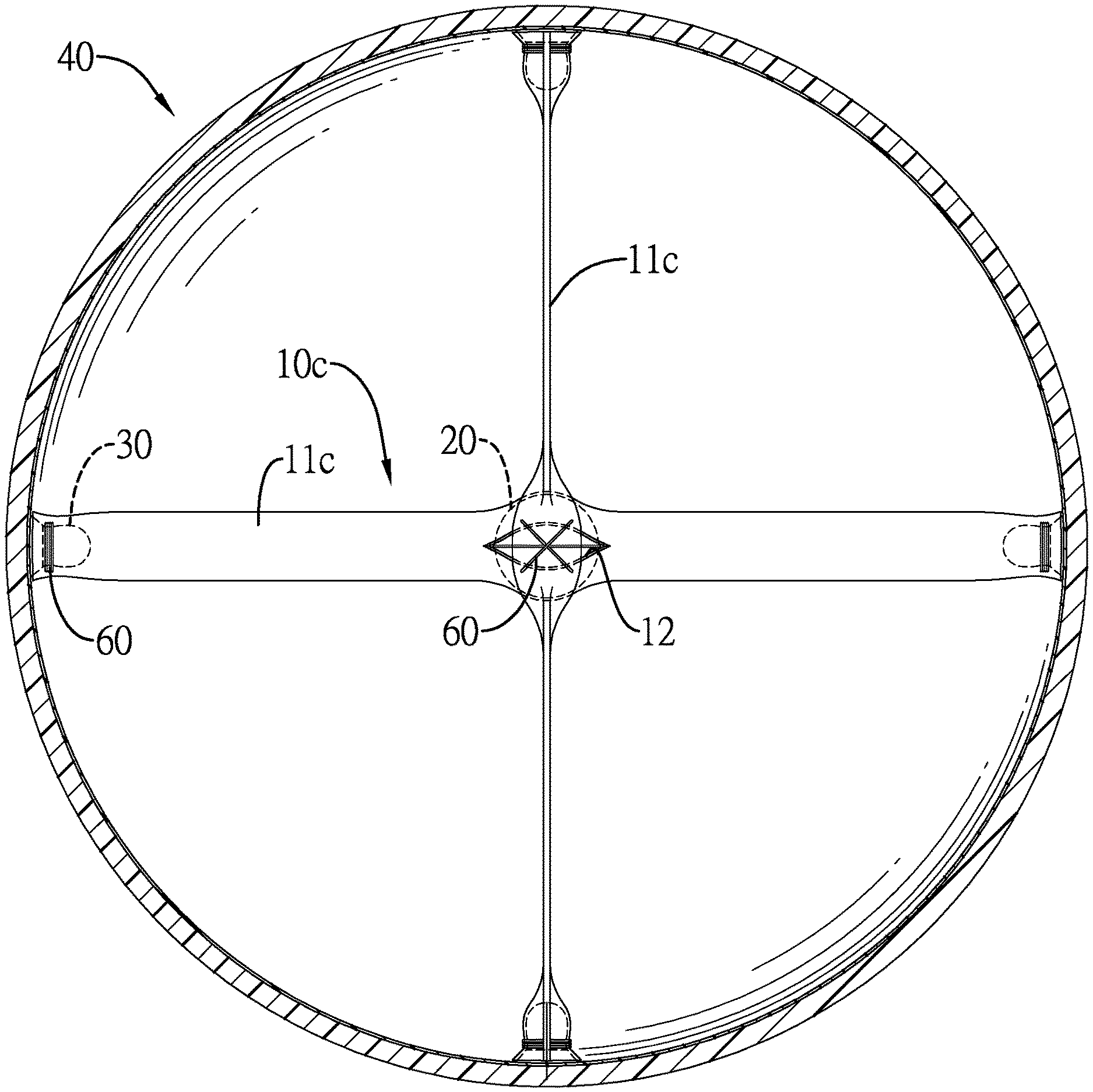
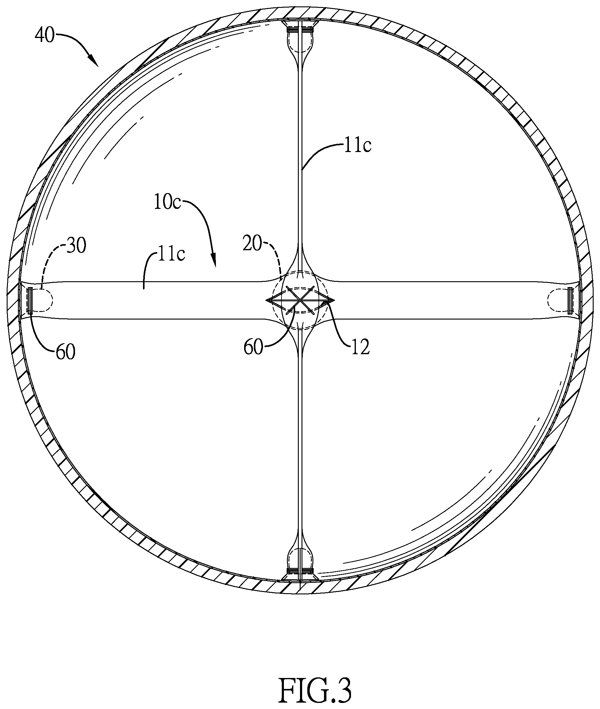
With reference to FIGS. 1 to 3, embodiments of a ball in accordance with the present invention each has a sensor assembling structure with an installation assembly 10a, 10b, 10c and a thermal insulation coat 20, multiple fastening joints 30, a hollow ball 40, and a sensor 50.
With reference to FIG. 1, the hollow ball 40 is a hollow sphere, is inflatable, and has an inner peripheral surface. In the first embodiment of the present invention, the thermal insulation coat 20 is a shell and has an outer peripheral surface. The thermal insulation coat 20 is made of a thermal insulation material such as glass fiber or polytetrafluoroethylene, PTFE, and is able to keep the heat out and thermally insulate the sensor. The thermal insulation coat 20 is disposed at a central position inside the hollow ball 40. The sensor 50 is disposed within the thermal insulation coat 20, is wrapped around by the thermal insulation coat 20, and is disposed at the central position inside the hollow ball 40. In the first embodiment, the thermal insulation coat 20 is a shell made of a thermal insulation material. Practically, the thermal insulation coat 20 may be a layer of thermal insulation material coated on the sensor 50. The sensor 50 can be a device that is designed for measuring speeds, detecting vibrations, etc.
The installation assembly 10a is disposed within the hollow ball 40 and has two connecting members 11a. Each connecting member 11a is also made of a thermal insulation material such as glass fiber or polytetrafluoroethylene. Each connecting member 11a is hollow and elongated. Each connecting member 11a has a middle section being flat and a first end and a second end opposite each other. The first end of each connecting member 11a is connected to the outer peripheral surface of the thermal insulation coat 20. The second end of each connecting member 11a is connected to the inner peripheral surface of the hollow ball 40. The two connecting members 11a are in alignment with each other. More specifically, in the first embodiment, the multiple fastening joints 30 are two fastening joints 30 protruding from the inner peripheral surface of the hollow ball 40. The second ends of the two connecting members 11a are respectively mounted around the two fastening joints 30 and are tightened by threads 60 mounted through the second ends to be respectively fixed to the two fastening joints 30. The second ends of the two connecting members 11a are connected to the inner peripheral surface of the hollow ball 40 via the two fastening joints 30, respectively.
With reference to FIG. 2, the second embodiment is similar to the first embodiment. In the second embodiment, the installation assembly 10b has three connecting members 11b. Each connecting member 11b is hollow and elongated. Each connecting member 11b has a middle section being flat and a first end and a second end opposite each other. The multiple fastening joints 30 are three fastening joints 30 accordingly. The first end of each connecting member 11b is connected to the outer peripheral surface of the thermal insulation coat 20. The second end of each connecting member 11b is mounted around a corresponding one of the three fastening joints 30 and is tightened by threads 60.
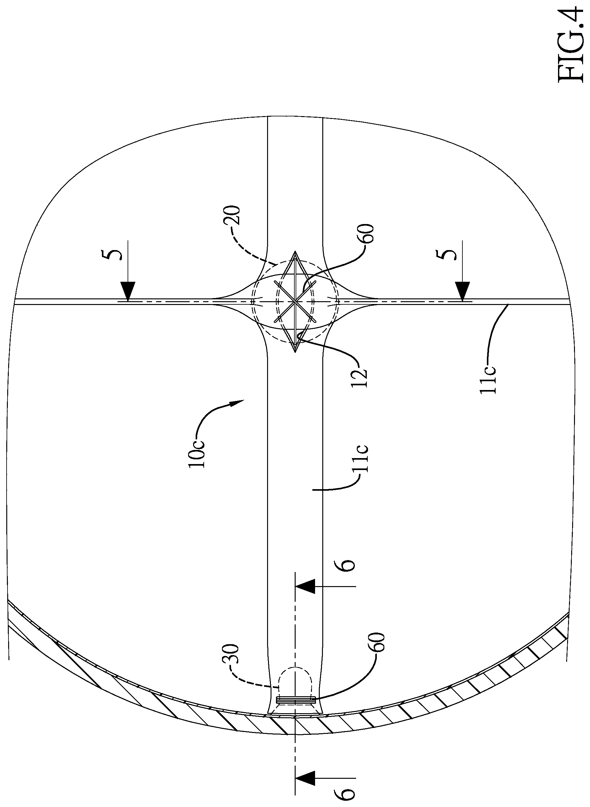
With reference to FIGS. 3 to 5, the third embodiment is similar to the first and the second embodiments. In the third embodiment, the installation assembly 10c has two connecting members 11c. Each connecting member 11c is hollow and elongated. Each connecting member 11c has a middle section being flat and a first end and a second end opposite each other. The first end and the second end of each connecting member 11c are both connected to the inner peripheral surface of the hollow ball 40 via the multiple fastening joints 30. Each connecting member 11c has an inserting hole 12 defined through a middle section of the connecting member 11c for the other one of the two connecting members 11c to be mounted through. The middle sections of the two connecting members 11c are intersected with each other accordingly. The thermal insulation coat 20 and the sensor 50 therein are disposed within one of the two connecting members 11c. The middle sections of the two connecting members 11c are tightened by threads 60 mounted through the middle sections to keep the sensor 50 and the thermal insulation coat 20 disposed at the central position inside the hollow ball 40. The threads 60 may be made of materials with or without elasticity.
The installation assemblies 11a, 11b, 11c can be applied to hollow balls such as basketballs, volleyballs, soccer balls, and so on. The hollow balls are not restricted to athletic balls. Amounts and lengths of the connecting members 11a, 11b, 11c can be adjusted according to specifications and pounds per square inch (PSI) of the hollow balls.
Furthermore, the connecting members 11a, 11b, 11c of the installation assembly 10a, 10b, 10c and the thermal insulation coat 20 are made of a thermal insulation material and can withstand heat generated by thermal treatment during manufacturing to prevent the sensor 50 from being damaged by the heat.
With reference to FIGS. 1 to 3, when the hollow ball 40 is inflated, tensions provided by the connecting members 11a, 11b, 11c keep the thermal insulation coat 20 and the sensor 50 therein at the central position of the hollow ball 40 without altering a center of mass of the hollow ball 40. Flying paths of the hollow ball 40 would not be affected by the sensor 50 inside the hollow ball 40. The sensor 50 can be linked to a mobile device of an athlete to transmit collected data to the mobile device. The athlete can improve posture according to the data collected by the sensor 50 to promote efficiency of drills.
In conclusion of the above, the sensor assembling structure in accordance with the present invention keeps the thermal insulation coat 20 at the central position inside the inflated hollow ball 40 via the installation assemblies 10a, 10b, 10c connected to the inner peripheral surface of the hollow ball 40. The sensor assembling structure in accordance with the present invention avoids shifting of the center of mass of the hollow ball 40 and provides the athlete with data collected from the sensor 50 within the hollow ball 40 to promote training effects.
Even though numerous characteristics and advantages of the present invention have been set forth in the foregoing description, together with details of the structure and features of the invention, the disclosure is illustrative only. Changes may be made in the details, especially in matters of shape, size, and arrangement of parts within the principles of the invention to the full extent indicated by the broad general meaning of the terms in which the appended claims are expressed.
* * * * *
D00000
D00001
D00002
D00003
D00004
D00005
XML
uspto.report is an independent third-party trademark research tool that is not affiliated, endorsed, or sponsored by the United States Patent and Trademark Office (USPTO) or any other governmental organization. The information provided by uspto.report is based on publicly available data at the time of writing and is intended for informational purposes only.
While we strive to provide accurate and up-to-date information, we do not guarantee the accuracy, completeness, reliability, or suitability of the information displayed on this site. The use of this site is at your own risk. Any reliance you place on such information is therefore strictly at your own risk.
All official trademark data, including owner information, should be verified by visiting the official USPTO website at www.uspto.gov. This site is not intended to replace professional legal advice and should not be used as a substitute for consulting with a legal professional who is knowledgeable about trademark law.