Cochlear implants and magnets for use with same
Crawford , et al. October 20, 2
U.S. patent number 10,806,936 [Application Number 15/770,207] was granted by the patent office on 2020-10-20 for cochlear implants and magnets for use with same. This patent grant is currently assigned to Advanced Bionics AG. The grantee listed for this patent is ADVANCED BIONICS AG. Invention is credited to Scott A. Crawford, James George Elcoate Smith.
| United States Patent | 10,806,936 |
| Crawford , et al. | October 20, 2020 |
Cochlear implants and magnets for use with same
Abstract
A cochlear including a cochlear lead, a housing including a magnet pocket and a magnet aperture, a magnet, located within the magnet pocket, having a top surface adjacent to the magnet aperture that defines a top magnet outer perimeter and a bottom surface adjacent to the bottom wall that defines a bottom magnet outer perimeter that is greater than the top magnet outer perimeter, an antenna within the housing, a stimulation processor within the housing.
| Inventors: | Crawford; Scott A. (Castaic, CA), Smith; James George Elcoate (Santa Clarita, CA) | ||||||||||
|---|---|---|---|---|---|---|---|---|---|---|---|
| Applicant: |
|
||||||||||
| Assignee: | Advanced Bionics AG (Staefa,
CH) |
||||||||||
| Family ID: | 54771218 | ||||||||||
| Appl. No.: | 15/770,207 | ||||||||||
| Filed: | November 20, 2015 | ||||||||||
| PCT Filed: | November 20, 2015 | ||||||||||
| PCT No.: | PCT/US2015/062015 | ||||||||||
| 371(c)(1),(2),(4) Date: | April 22, 2018 | ||||||||||
| PCT Pub. No.: | WO2017/087004 | ||||||||||
| PCT Pub. Date: | May 26, 2017 |
Prior Publication Data
| Document Identifier | Publication Date | |
|---|---|---|
| US 20180304078 A1 | Oct 25, 2018 | |
| Current U.S. Class: | 1/1 |
| Current CPC Class: | A61N 1/0541 (20130101); A61N 1/36038 (20170801); A61N 1/3758 (20130101); A61N 1/37217 (20130101); H04R 2225/67 (20130101); H04R 25/606 (20130101) |
| Current International Class: | A61N 1/375 (20060101); A61N 1/05 (20060101); A61N 1/36 (20060101); A61N 1/372 (20060101); H04R 25/00 (20060101) |
References Cited [Referenced By]
U.S. Patent Documents
| 4352960 | October 1982 | Dormer et al. |
| 4595390 | June 1986 | Hakim et al. |
| 4606329 | August 1986 | Hough |
| 4618949 | October 1986 | Lister |
| RE32947 | June 1989 | Dormer et al. |
| 5290281 | March 1994 | Tschakaloff |
| 5755762 | May 1998 | Bush |
| 5824022 | October 1998 | Zilberman et al. |
| 5945762 | August 1999 | Chen et al. |
| 6178353 | January 2001 | Griffith et al. |
| 6190305 | February 2001 | Ball et al. |
| 6217508 | April 2001 | Ball et al. |
| 6227820 | May 2001 | Jarvik |
| 6292678 | September 2001 | Hall et al. |
| 6348070 | February 2002 | Teissl et al. |
| 6358281 | March 2002 | Berrang et al. |
| 6599321 | July 2003 | Hyde, Jr. |
| 6838963 | January 2005 | Zimmerling |
| 7091806 | August 2006 | Zimmerling et al. |
| 7190247 | March 2007 | Zimmerling |
| 7566296 | July 2009 | Zimmerling et al. |
| 7609061 | October 2009 | Hochmair |
| 7642887 | January 2010 | Zimmerling |
| 7680525 | March 2010 | Damadian |
| 7774069 | August 2010 | Olson et al. |
| 7856986 | December 2010 | Darley |
| 7881800 | February 2011 | Daly et al. |
| 7976453 | July 2011 | Zimmerling et al. |
| 8013699 | September 2011 | Zimmerling |
| 8118725 | February 2012 | Zimmerling et al. |
| 8255058 | August 2012 | Gibson et al. |
| 8340774 | December 2012 | Hochmair et al. |
| 8634909 | January 2014 | Zimmerling et al. |
| 8733494 | May 2014 | Leigh |
| 8734475 | May 2014 | Ekvall et al. |
| 8744106 | June 2014 | Ball |
| 8758394 | June 2014 | Zimmerling et al. |
| 8787608 | July 2014 | Van Himbeeck et al. |
| 8790409 | July 2014 | Van den Heuvel et al. |
| 8825171 | September 2014 | Thenuwara et al. |
| 8891795 | November 2014 | Andersson |
| 8897475 | November 2014 | Ball et al. |
| RE45701 | September 2015 | Zimmerling et al. |
| 9126010 | September 2015 | Shah et al. |
| 9162054 | October 2015 | Dalton |
| 9227064 | January 2016 | Duftner |
| 9295425 | March 2016 | Ball |
| 9314625 | April 2016 | Kasic, II et al. |
| 9352149 | May 2016 | Thenuwara et al. |
| RE46057 | July 2016 | Zimmerling et al. |
| 9392382 | July 2016 | Nagl et al. |
| 9420388 | August 2016 | Ball |
| 9549267 | January 2017 | Nagl et al. |
| 9615181 | April 2017 | Nagl et al. |
| 9656065 | May 2017 | Tourrel et al. |
| 9919154 | March 2018 | Lee |
| 9931501 | April 2018 | Smyth |
| 10300276 | May 2019 | Lee et al. |
| 2004/0012470 | January 2004 | Zimmerling et al. |
| 2004/0260362 | December 2004 | Darley |
| 2005/0001703 | January 2005 | Zimmerling |
| 2005/0004629 | January 2005 | Gibson et al. |
| 2005/0062567 | March 2005 | Zimmerling et al. |
| 2006/0244560 | November 2006 | Zimmerling et al. |
| 2007/0053536 | March 2007 | Westerkull |
| 2007/0126540 | June 2007 | Zimmerling |
| 2008/0103350 | May 2008 | Farone |
| 2008/0195178 | August 2008 | Kuzma |
| 2009/0048580 | February 2009 | Gibson |
| 2009/0099403 | April 2009 | Zimmerling et al. |
| 2009/0134721 | May 2009 | Zimmerling |
| 2009/0248155 | October 2009 | Parker |
| 2009/0287278 | November 2009 | Charvin |
| 2010/0004716 | January 2010 | Zimmerling et al. |
| 2010/0046778 | February 2010 | Crawford et al. |
| 2010/0046779 | February 2010 | Crawford et al. |
| 2011/0009925 | January 2011 | Leigh et al. |
| 2011/0022120 | January 2011 | Ball et al. |
| 2011/0068885 | March 2011 | Fullerton et al. |
| 2011/0218605 | September 2011 | Cryer |
| 2011/0224756 | September 2011 | Zimmerling et al. |
| 2011/0255731 | October 2011 | Ball |
| 2011/0264172 | October 2011 | Zimmerling et al. |
| 2012/0296155 | November 2012 | Ball |
| 2013/0079749 | March 2013 | Overstreet et al. |
| 2013/0184804 | July 2013 | Dalton |
| 2013/0343588 | December 2013 | Karunasiri |
| 2014/0012069 | January 2014 | Ball |
| 2014/0012070 | January 2014 | Nagl et al. |
| 2014/0012071 | January 2014 | Nagl et al. |
| 2014/0012349 | January 2014 | Zimmerling |
| 2014/0121449 | May 2014 | Kasic et al. |
| 2014/0121586 | May 2014 | Bertrand et al. |
| 2014/0163692 | June 2014 | Van den Heuvel et al. |
| 2014/0343626 | November 2014 | Thenuwara et al. |
| 2015/0025613 | January 2015 | Nyberg, II et al. |
| 2015/0073205 | March 2015 | Ball et al. |
| 2015/0087892 | March 2015 | Tourrel et al. |
| 2015/0100109 | April 2015 | Feldman et al. |
| 2015/0265842 | September 2015 | Ridker |
| 2015/0367126 | December 2015 | Smyth |
| 2015/0382114 | December 2015 | Andersson et al. |
| 2016/0037273 | February 2016 | Gustafsson |
| 2016/0144170 | May 2016 | Gibson et al. |
| 2016/0205484 | July 2016 | Nagl et al. |
| 2016/0310737 | October 2016 | Tourrel et al. |
| 2016/0361537 | December 2016 | Leigh et al. |
| 2016/0381473 | December 2016 | Gustafsson |
| 2016/0381474 | December 2016 | Gustafsson et al. |
| 2017/0050027 | February 2017 | Andersson et al. |
| 2017/0078808 | March 2017 | Kennes |
| 2017/0156010 | June 2017 | Verma et al. |
| 2017/0239476 | August 2017 | Lee et al. |
| 2018/0028818 | February 2018 | Andersson et al. |
| 2018/0110985 | April 2018 | Walter |
| 2018/0110986 | April 2018 | Lee |
| 2018/0133486 | May 2018 | Smith |
| 2018/0185634 | July 2018 | Smyth |
| 2018/0296826 | October 2018 | Lee et al. |
| 2018/0369586 | December 2018 | Lee et al. |
| 2019/0046797 | February 2019 | Calixto et al. |
| 2019/0076649 | March 2019 | Lee et al. |
| 2117489 | May 2010 | EP | |||
| 2853287 | Apr 2015 | EP | |||
| 2560730 | Nov 2016 | EP | |||
| 3138605 | Mar 2017 | EP | |||
| 2098198 | Sep 2017 | EP | |||
| WO9858990 | Dec 1998 | WO | |||
| WO03081976 | Oct 2003 | WO | |||
| WO03092326 | Nov 2003 | WO | |||
| WO2004014269 | Feb 2004 | WO | |||
| WO2004014270 | Feb 2004 | WO | |||
| WO2007024657 | Mar 2007 | WO | |||
| WO2009124045 | Oct 2009 | WO | |||
| WO2009124174 | Oct 2009 | WO | |||
| WO2009149069 | Dec 2009 | WO | |||
| WO2010000027 | Jan 2010 | WO | |||
| WO2010083554 | Jul 2010 | WO | |||
| WO2011011409 | Jan 2011 | WO | |||
| WO2011109486 | Sep 2011 | WO | |||
| WO2011133747 | Oct 2011 | WO | |||
| WO2013043176 | Mar 2013 | WO | |||
| WO2013063355 | May 2013 | WO | |||
| WO2014011441 | Jan 2014 | WO | |||
| WO2014011582 | Jan 2014 | WO | |||
| WO2014046662 | Mar 2014 | WO | |||
| WO2014164023 | Oct 2014 | WO | |||
| WO2015065442 | May 2015 | WO | |||
| WO2016016821 | Feb 2016 | WO | |||
| WO2016191429 | Dec 2016 | WO | |||
| WO2016207856 | Dec 2016 | WO | |||
| WO2017027045 | Feb 2017 | WO | |||
| WO2017027046 | Feb 2017 | WO | |||
| WO2017029615 | Feb 2017 | WO | |||
| WO2017034530 | Mar 2017 | WO | |||
| WO2017046650 | Mar 2017 | WO | |||
| WO2017087004 | May 2017 | WO | |||
| WO2017105510 | Jun 2017 | WO | |||
| WO2017105511 | Jun 2017 | WO | |||
| WO2017105604 | Jun 2017 | WO | |||
| WO2017172566 | Oct 2017 | WO | |||
| WO2018190813 | Oct 2018 | WO | |||
| WO2018191314 | Oct 2018 | WO | |||
| WO2018199936 | Nov 2018 | WO | |||
Other References
|
US. Appl. No. 15/568,469, filed Oct. 21, 2017, 20180110985A1. cited by applicant . U.S. Appl. No. 16/060,383, filed Jun. 7, 2018, 20180369586 A1. cited by applicant . U.S. Appl. No. 15/591,054, filed May 9, 2017, U.S. Pat. No. 9,919,154. cited by applicant . U.S. Appl. No. 16/009,600, filed Jun. 15, 2018, 20180296826A1. cited by applicant . U.S. Appl. No. 15/568,470, filed Oct. 21, 2017, 20180110986A1. cited by applicant . U.S. Appl. No. 16/101,390, file Aug. 10, 2018, 20190046797 A1. cited by applicant . U.S. Appl. No. 15/703,808, filed Sep. 13, 2017. cited by applicant . U.S. Appl. No. 15/805,025, filed Nov. 6, 2017, 20180133486 A1. cited by applicant . Ju Hyun Jeon et al., "Reversing the Polarity of a Cochlear Implant Magnet After Magnetic Resonance Imaging," Auris Nasus Larynx, vol. 39, No. 4, pp. 415-417, Aug. 1, 2012. cited by applicant . Teissl et al., "Magentic Resonance Imaging and Cochlear Implants: Compatibility and Safety Aspects," Journal of Magnetic Resonance Imaging, Society for Magnetic Resonance Imaging, vol. 9, No. 1, pp. 26-38, Jan. 1, 1999. cited by applicant . PCT International Search and Written Opinion dated Jul. 22, 2016 for PCT App. Ser. No. PCT/US2015/062015. cited by applicant . U.S. Appl. No. 16/403,582, filed May 5, 2019. cited by applicant . U.S. Appl. No. 15/568,470, filed Oct. 21, 2017, U.S. Pat. No. 10,300,276. cited by applicant . U.S. Appl. No. 16/101,390, filed Aug. 10, 2018, 20190046797 A1. cited by applicant . U.S. Appl. No. 15/703,808, filed Sep. 13, 2017, 20190076649 A1. cited by applicant. |
Primary Examiner: Porter; Allen
Attorney, Agent or Firm: Henricks Slavin LLP
Claims
We claim:
1. A cochlear implant, comprising: a cochlear lead including a plurality of electrodes; a flexible housing formed from a first flexible material having a first hardness and including a magnet pocket, a top wall above the magnet pocket, a bottom wall that does not include an opening below the magnet pocket, and a magnet aperture that extends through the top wall to the magnet pocket; a magnet, located within the magnet pocket, having a top surface adjacent to the magnet aperture that defines a top magnet outer perimeter, a bottom surface adjacent to the bottom wall that defines a bottom magnet outer perimeter that is greater than the top magnet outer perimeter, and a side surface between the top surface and the bottom surface; a flexible buttress located within the flexible housing adjacent to the side surface of the magnet, the flexible buttress being formed from a second flexible material having a second hardness that is greater than the first hardness; an antenna within the flexible housing and adjacent to the magnet pocket; and a stimulation processor within the flexible housing operably connected to the antenna and to the cochlear lead.
2. A cochlear implant as claimed in claim 1, wherein the magnet defines a frustoconical shape; and the flexible buttress has an inner surface that defines a frustoconical shape.
3. A cochlear implant, comprising: a cochlear lead including a plurality of electrodes; a flexible housing, formed from a first flexible material having a first hardness, including a magnet pocket, a top wall above the magnet pocket, a bottom wall that does not include an opening below the magnet pocket, and a magnet aperture that extends through the top wall to the magnet pocket; a magnet, located within the magnet pocket, including a top surface adjacent to the magnet aperture, a bottom surface adjacent to the bottom wall, and a side surface between the top and bottom surfaces; a flexible buttress located within the flexible housing and adjacent to the side surface of the magnet, the flexible buttress being formed from a second flexible material having a second hardness that is greater than the first hardness; an antenna within the housing and adjacent to the magnet pocket; and a stimulation processor within the housing operably connected to the antenna and to the cochlear lead.
4. A cochlear implant as claimed in claim 3, wherein the second flexible material is from 27% to 63% harder than the first material.
5. A cochlear implant as claimed in claim 3, wherein the first material has a hardness from 70 to 90 Shore A; the second flexible has a hardness from 55 to 70 Shore A.
6. A cochlear implant as claimed in claim 3, wherein the top surface of the magnet defines a top magnet outer perimeter and the bottom surface of the magnet defines a bottom magnet outer perimeter that is greater than the top magnet outer perimeter; and the flexible buttress has an inner surface with a top inner surface perimeter and a bottom inner surface perimeter that is greater than the top inner surface perimeter.
7. A cochlear implant as claimed in claim 3, wherein the housing is formed from a first silicone elastomer; and the buttress is formed from a second silicone elastomer that is harder than the first silicone elastomer.
Description
CROSS-REFERENCE TO RELATED APPLICATIONS
This application is the U.S. National Stage of PCT App. Ser. No. PCT/US2015/062015, filed Nov. 20, 2015.
BACKGROUND
1. Field
The present disclosure relates generally to the implantable portion of implantable cochlear stimulation (or "ICS") systems.
2. Description of the Related Art
ICS systems are used to help the profoundly deaf perceive a sensation of sound by directly exciting the intact auditory nerve with controlled impulses of electrical current. Ambient sound pressure waves are picked up by an externally worn microphone and converted to electrical signals. The electrical signals, in turn, are processed by a sound processor, converted to a pulse sequence having varying pulse widths and/or amplitudes, and transmitted to an implanted receiver circuit of the ICS system. The implanted receiver circuit is connected to an implantable electrode array that has been inserted into the cochlea of the inner ear, and electrical stimulation current is applied to varying electrode combinations to create a perception of sound. The electrode array may, alternatively, be directly inserted into the cochlear nerve without residing in the cochlea. A representative ICS system is disclosed in U.S. Pat. No. 5,824,022, which is entitled "Cochlear Stimulation System Employing Behind-The-Ear Sound processor With Remote Control" and incorporated herein by reference in its entirety. Examples of commercially available ICS sound processors include, but are not limited to, the Advanced Bionics.TM. Harmony.TM. BTE sound processor, the Advanced Bionics.TM. Naida.TM. BTE sound processor and the Advanced Bionics.TM. Neptune.TM. body worn sound processor.
As alluded to above, some ICS systems include an implantable cochlear stimulator (or "cochlear implant"), a sound processor unit (e.g., a body worn processor or behind-the-ear processor), and a microphone that is part of, or is in communication with, the sound processor unit. The cochlear implant communicates with the sound processor unit and, some ICS systems include a headpiece that is in communication with both the sound processor unit and the cochlear implant. The headpiece communicates with the cochlear implant by way of a transmitter (e.g., an antenna) on the headpiece and a receiver (e.g., an antenna) on the implant. Optimum communication is achieved when the transmitter and the receiver are aligned with one another. To that end, the headpiece and the cochlear implant may include respective positioning magnets that are attracted to one another, and that maintain the position of the headpiece transmitter over the implant receiver. The implant magnet may, for example, be located within a pocket in the cochlear implant housing.
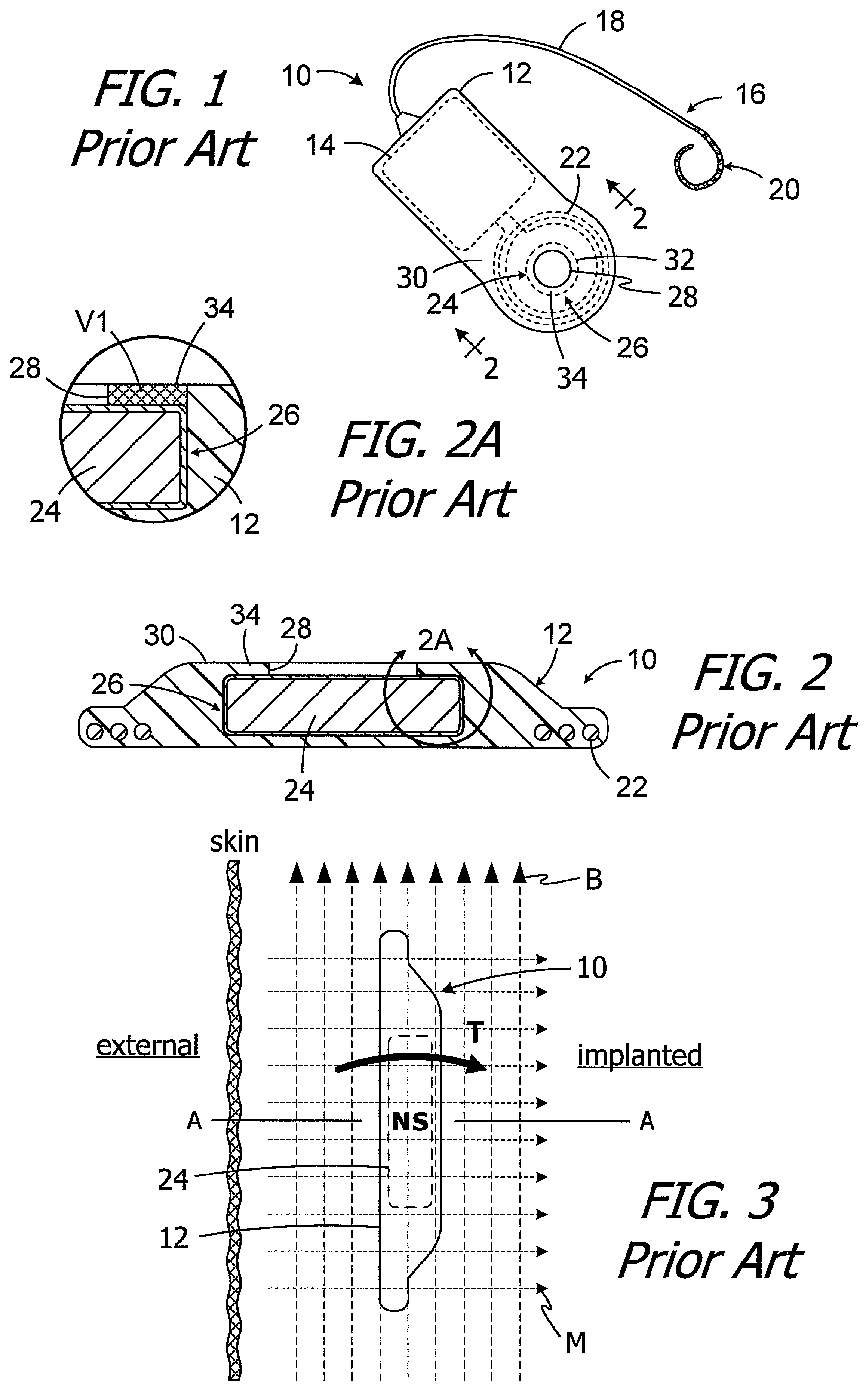
One example of a conventional cochlear implant (or "implantable cochlear stimulator") is the cochlear implant 10 illustrated in FIGS. 1 and 2. The cochlear implant 10 includes a flexible housing 12 formed from a silicone elastomer or other suitable material, a processor assembly 14, a cochlear lead 16 with a flexible body 18 and an electrode array 20, and an antenna 22 that may be used to receive data and power by way of an external antenna that is associated with, for example, a sound processor unit. A cylindrical positioning magnet 24, with north and south magnetic dipoles that are aligned in the axial direction of the disk, is located within the housing 12. The magnet 24 is used to maintain the position of a headpiece transmitter over the antenna 22.
It is sometimes necessary to remove the magnet from the cochlear implant, and then reinsert the magnet, in situ, i.e., with the cochlear implant accessed by way of an incision in the skin. To that end, the positioning magnet 24 is carried within an internal magnet pocket 26 and can be inserted into, and removed from, the housing pocket by way of a magnet aperture 28 that extends through the housing top wall 30. The magnet 22 is larger than the magnet aperture 28, i.e., the outer perimeter of the magnet is greater than the perimeter of the magnet aperture. The portion of the top wall 30 between the aperture 28 and the outer edge 32 of the magnet 24 forms a retainer 34 that, absent deformation of the aperture and retainer, prevents the magnet from coming out of the housing 12. The volume V1 of the ring of housing material that forms the retainer 34 (which is the same flexible material that forms the remainder of the housing 12) is shown with cross-hatching in the cross-section illustrated in FIG. 2A. During installation and removal, the aperture 28 and retainer 34 are stretched or otherwise deformed so that the magnet 24 can pass through the aperture 28.
The present inventors have determined that conventional cochlear implants are susceptible to improvement. For example, some conventional cochlear implants may not be compatible with magnetic resonance imaging ("MRI") systems. As illustrated in FIG. 3, the implant magnet 24 produces a magnetic field M in a direction that is perpendicular to the patient's skin and parallel to the axis A. This magnetic field direction is not aligned with, and may be perpendicular to (as shown), the direction of the MRI magnetic field B. The misalignment of the interacting magnetic fields M and B is problematic for a number of reasons. The dominant MRI magnetic field B (typically 1.5 Tesla or more) may generate a significant amount of torque T on the implant magnet 24. The torque T may be sufficient to deform the retainer 34 and dislodge the implant magnet 24 from the pocket 26 by way of the aperture 28 and/or reverse the magnet. In particular, the present inventors have determined that the volume V1 of flexible housing material that forms the retainer 34 can be insufficient to resist the torque T on the implant magnet 24.
One proposed solution involves surgically removing the implant magnet 24 prior to an MRI procedure and then surgically replacing the implant magnet thereafter. The present inventors have determined that a solution which allows an MRI procedure to be performed without magnet removal/replacement surgery, but which also permits magnet removal/replacement if otherwise necessary, would be desirable.
SUMMARY
A cochlear implant in accordance with one of the present inventions includes a cochlear lead, a housing including a magnet pocket and a magnet aperture, a magnet, located within the magnet pocket, having a top surface adjacent to the magnet aperture that defines a top magnet outer perimeter and a bottom surface adjacent to the bottom wall that defines a bottom magnet outer perimeter that is greater than the top magnet outer perimeter, an antenna within the housing, a stimulation processor within the housing. The present inventions also include systems with such a cochlear implant in combination with a headpiece.
A cochlear implant in accordance with one of the present inventions includes a cochlear lead, a flexible housing formed from a first flexible material having a first hardness and including a magnet pocket and a magnet aperture, a magnet with a side surface within the magnet pocket, a flexible buttress located within the flexible housing and adjacent to the side surface of the magnet, the flexible buttress being formed from a second flexible material having a second hardness that is greater than the first hardness, an antenna within the housing, a stimulation processor within the housing. The present inventions also include systems with such a cochlear implant in combination with a headpiece.
There are a number of advantages associated with such apparatus. For example, the torque applied to the implant magnet by a strong magnetic field, such as an MRI magnetic field, will not dislodge the implant magnet from the within the housing and/or reverse the magnet. As a result, surgical removal of the cochlear implant magnet prior to an MRI procedure, and then surgical replacement thereafter, is not required. In those instances where removal is required, the present cochlear implants need not preclude such removal and replacement. Additionally, the present cochlear implants prevent the implant magnet from being dislodged and/or reversed without increasing the thickness and volume of the implant or substantially increasing the rigidity of the implant.
The above described and many other features of the present inventions will become apparent as the inventions become better understood by reference to the following detailed description when considered in conjunction with the accompanying drawings.
BRIEF DESCRIPTION OF THE DRAWINGS
Detailed descriptions of the exemplary embodiments will be made with reference to the accompanying drawings.
FIG. 1 is a plan view of a conventional cochlear implant.
FIG. 2 is a section view taken along line 2-2 in FIG. 1.
FIG. 2A is an enlarged view of a portion of FIG. 2.
FIG. 3 is a side view showing a conventional cochlear implant in an MRI magnetic field.
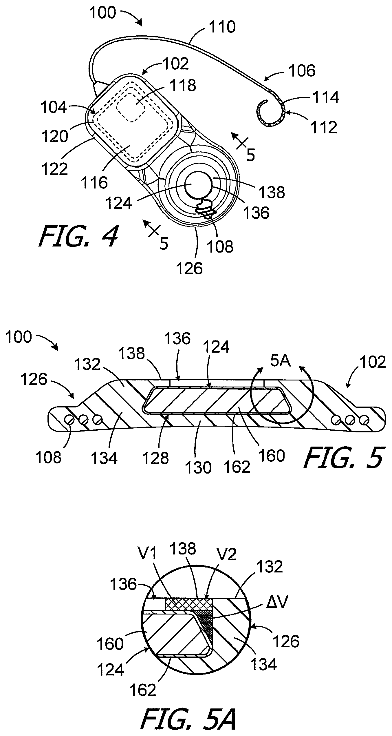
FIG. 4 is a plan view of a cochlear implant in accordance with one embodiment of a present invention.
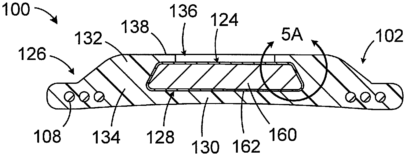
FIG. 5 is a section view taken along line 5-5 in FIG. 4.
FIG. 5A is an enlarged view of a portion of FIG. 5.
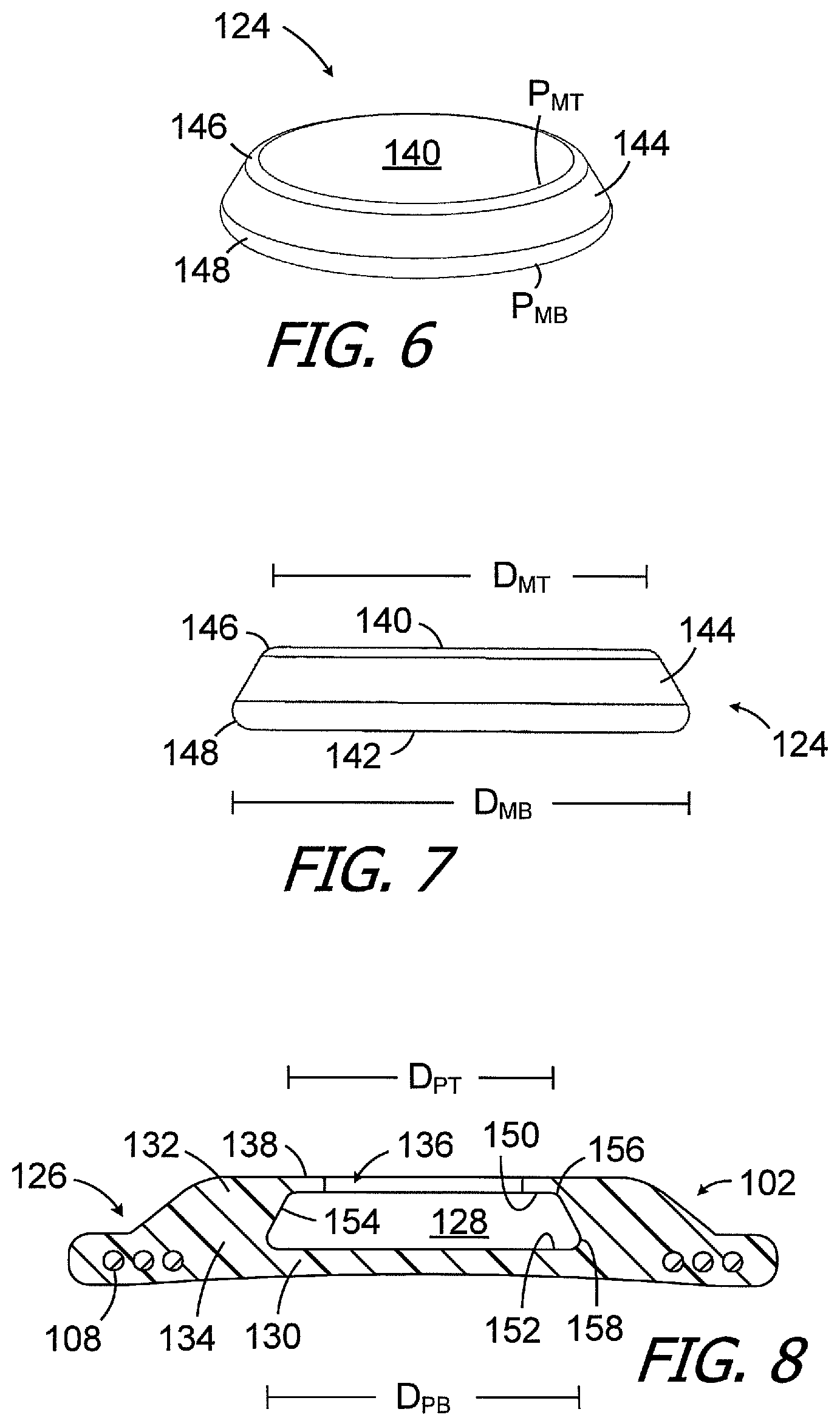
FIG. 6 is a perspective view of a magnet in accordance with one embodiment of a present invention.
FIG. 7 is a side view of the magnet illustrated in FIG. 6.
FIG. 8 is the section view illustrated in FIG. 5 with the magnet removed.
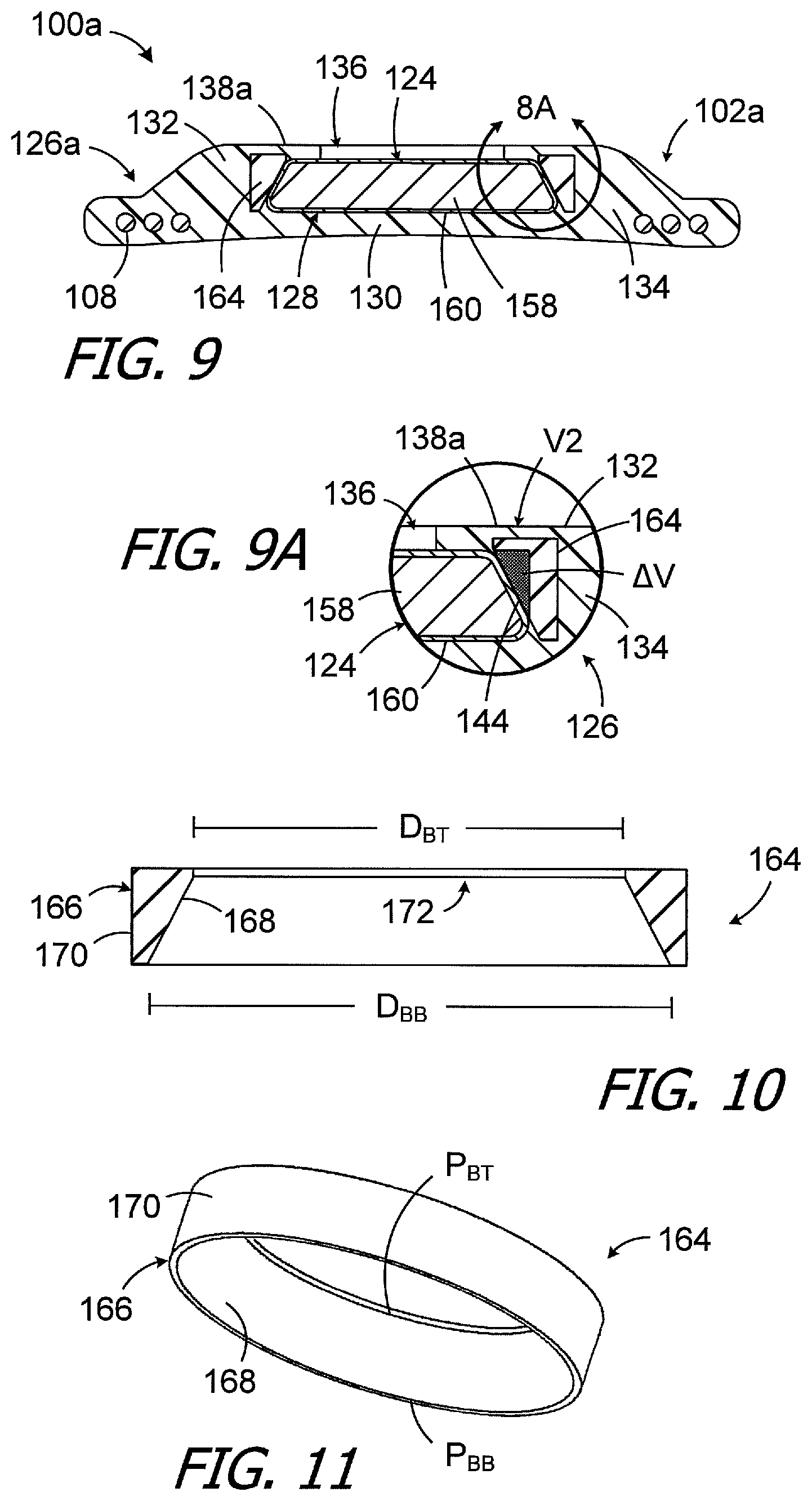
FIG. 9 is a section view of a cochlear implant in accordance with one embodiment of a present invention.
FIG. 9A is an enlarged view of a portion of FIG. 9.
FIG. 10 is a section view of a flexible magnet buttress in accordance with one embodiment of a present invention.
FIG. 11 is a perspective view of the flexible magnet buttress illustrated in FIG. 10.
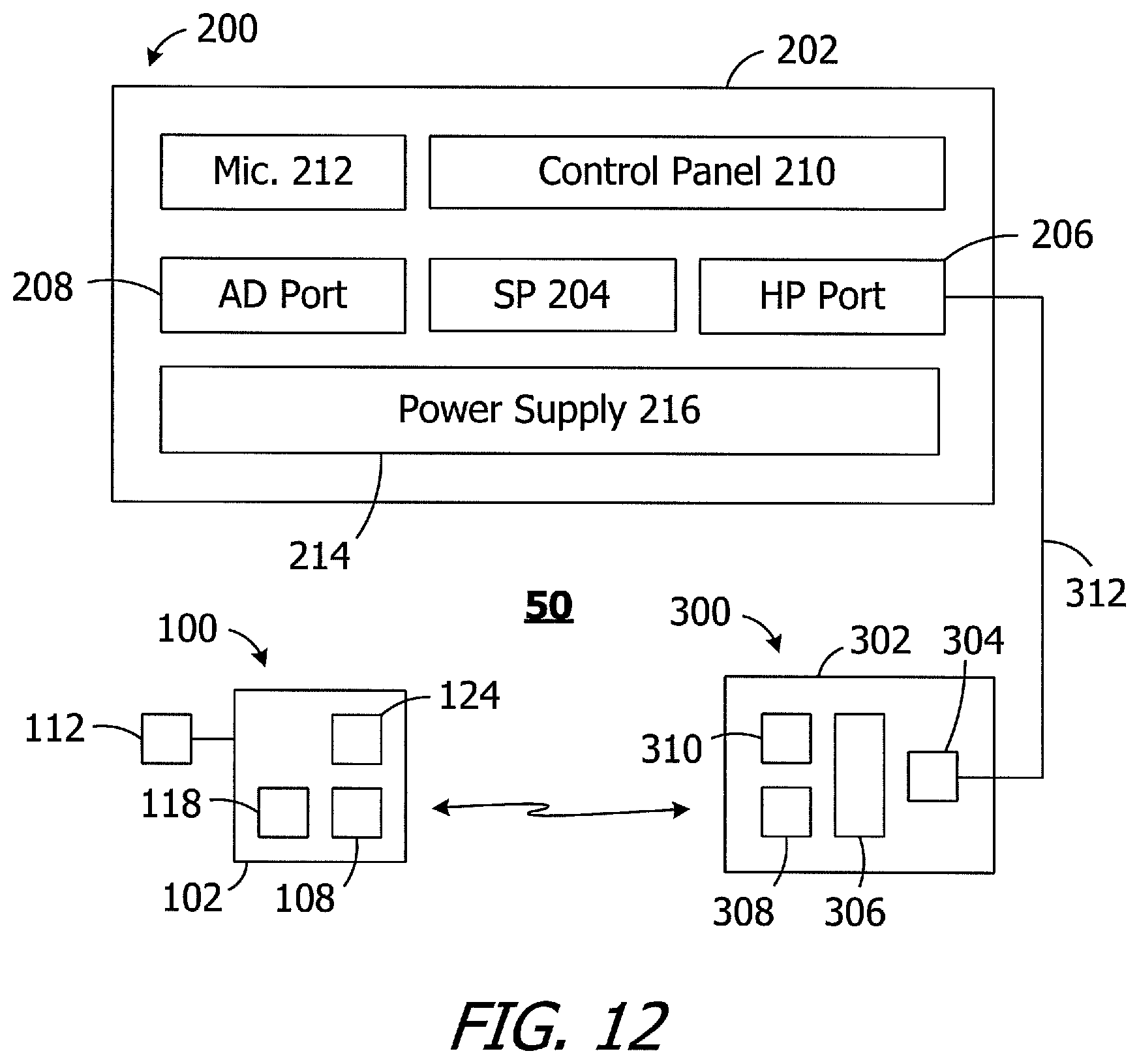
FIG. 12 is a block diagram of a cochlear implant system in accordance with one embodiment of a present invention.
DETAILED DESCRIPTION OF THE EXEMPLARY EMBODIMENTS
The following is a detailed description of the best presently known modes of carrying out the inventions. This description is not to be taken in a limiting sense, but is made merely for the purpose of illustrating the general principles of the inventions.
One example of a cochlear implant (or "implantable cochlear stimulator") in accordance with the present inventions is the cochlear implant 100 illustrated in FIGS. 4-8. Referring first to FIG. 4, the exemplary cochlear implant 100 includes a resilient flexible housing 102 formed from a silicone elastomer or other suitable material, a processor assembly 104, a cochlear lead 106, and an antenna 108 that may be used to receive data and power by way of an external antenna that is associated with, for example, a sound processor unit. The cochlear lead 106 may include a flexible body 110, an electrode array 112 at one end of the flexible body 102, and a plurality of wires (not shown) that extend through the flexible body from the electrodes 114 (e.g., platinum electrodes) in the array 112 to the other end of the flexible body. The exemplary antenna 108 is a coil antenna with one or more loops (or "turns"), and three loops are shown in the illustrated embodiment. The exemplary processor assembly 104, which is connected to the electrode array 112 and antenna 108, includes a printed circuit board 116 with a stimulation processor 118 that is located within a hermetically sealed case 120. The stimulation processor 118 converts stimulation data into stimulation signals that stimulate the electrodes 114 of the electrode array 112. The hermetically sealed case 120 is located within a processor portion 122 of the housing 102. A positioning magnet 124 is located within an antenna portion 126 of the housing 102. The magnet 124, which is used to maintain the position of a headpiece transmitter over the antenna 108, is centered relative to the antenna 108.
Turning to FIG. 5, the exemplary housing antenna portion 126 includes a magnet pocket 128 which is surrounded by a bottom wall 130 that is located under the magnet pocket (in the illustrated orientation), a top wall 132 that is located above the magnet pocket (in the illustrated orientation) and a side wall 134 that is lateral of, and extends around, the magnet pocket. During use, the housing bottom wall 130 faces the patient's skull and the outer surface of the bottom wall defines a portion of the bottom surface of the cochlear implant 100, which is the surface of the cochlear implant that faces the patient's skull. The magnet 124 can be inserted into, and removed from, the magnet pocket 128 by way of a magnet aperture 136 that extends through the housing top wall 132. The magnet 124 is larger than the magnet aperture 136 and portions of the top wall 132 and side wall 134 between the magnet aperture 136 and the side surface of the magnet 124 form a retainer 138.
As the strength of a conventional retainer (e.g., retainer 34 in FIG. 2) may be insufficient to prevent a conventional magnet from being dislodged during an MRI procedure, the present implant housing 102 and magnet 124 are configured so as to increase the volume of material that defines the retainer 138, as compared to the conventional retainer in an otherwise identical cochlear implant, without increasing the thickness and volume of the implant. To that end, and referring to FIGS. 6-8, the exemplary magnet 124 has a top surface 140, a bottom surface 142, and a side surface 144 between the top and bottom surfaces. The perimeter P.sub.MT of the top surface 140 is less than the perimeter P.sub.MB of the bottom surface 142. In the illustrated implementation, the magnet 124 has a frustoconical shape and, accordingly, the top and bottom surface perimeters P.sub.MT and P.sub.MB are circular and the diameter D.sub.MT of the top surface 140 is less than the diameter D.sub.MB of the bottom surface 142. The top and bottom corners (or "edges") 146 and 148 of the exemplary magnet 124 are rounded such that the cross-section is substantially trapezoidal (i.e., trapezoidal but for the rounded corners). The rounded edges ease insertion and removal of the magnet 124 to and from the pocket 128. The exemplary magnet pocket 128 (FIG. 8), which is similarly shaped, has a top surface 150, a bottom surface 152, a side surface 154 between the top and bottom surfaces, and rounded top and bottom corners 156 and 158. Here too, the perimeter of the top surface 150 is less than the perimeter of the bottom surface 152 and, in the illustrated implementation, the magnet pocket 128 has a frustoconical shape. The top and bottom surface perimeters of the magnet pocket 128 are, therefore, circular and the diameter D.sub.PT of the pocket top surface 150 is less than the diameter D.sub.PB of the bottom surface 122.
Turing to FIG. 5A, and as compared to the retainer 34, an additional volume .DELTA.V of material is added to the volume V1 to form the volume V2 that defines the retainer 138. The material in the volume V2, which is the same flexible material that forms the remainder of the housing 102, is shown with both cross-hatching (volume V1) and gray (volume .DELTA.V) in the cross-section illustrated in FIG. 5A. In the illustrated implementation, the respective configurations of the magnet 124 and the housing pocket 128 results in a retainer material volumetric increase of about 45%, as compared to an otherwise identical implant with a cylindrical magnet in a cylindrical pocket (e.g., the magnet 24 in pocket 26) having a diameter equal to the bottom surface diameter of the magnet 124, without increasing the volume or thickness of the implant. The torque generated by an MRI magnetic field will not dislodge the magnet 124 from the housing 102 and/or reverse the magnet within the housing in the manner described above with reference to FIGS. 1-3. Nevertheless, if necessary, the flexibility of the housing material allows the magnet 124 may be removed and replaced in situ. One example of a tool that may be used to remove the magnet 124, and then replace the magnet, is disclosed in PCT Pub. No. WO2014/164023.
Although the present inventions are not so limited, the exemplary magnet 124 includes a magnetic element 160 (FIGS. 5 and 5A) or magnetic object of some other shape formed from a ferromagnetic material and a thin hermetically sealed housing 162 formed from, for example, biocompatible metals and/or plastics. Such housing materials may, in some instances, be non-magnetic or paramagnetic. Suitable materials include, but are not limited to, titanium or titanium alloys, polyether ether ketone (PEEK), low-density polyethylene (LDPE), high-density polyethylene (HDPE) and polyamide. In particular, exemplary metals include commercially pure titanium (e.g., Grade 2) and the titanium alloy Ti-6Al-4V (Grade 5). With respect to size and shape, and although the present inventions are not so limited, in some implementations, the bottom magnet diameter D.sub.MB may range from 9 mm to 16 mm, the top magnet diameter D.sub.MT may range from 6 mm to 12 mm, and the thickness may range from 1.5 mm to 3.5 mm. The bottom magnet diameter D.sub.MB of the exemplary magnet 124 is 13.0 mm, the top magnet diameter D.sub.MT is 10.5 mm, and the thickness is 2.2 mm, in the illustrated embodiment. It should be noted, however, that magnet size is a function of the strength of the ferromagnetic material and, as stronger materials become available, the size may be reduced. The dimensions of the magnet pocket 128 may be equal to those of the magnet 124.
Another exemplary cochlear implant is generally represented by reference numeral 100 in FIGS. 9 and 9A. Cochlear implant 100a is substantially similar to cochlear implant 100 and similar elements are represented by similar reference numerals. Here, however, a portion of the material that forms the retainer is harder than the material that forms the remainder of the housing, thereby increasing the strength of the retainer. By way of example, but not limitation, the exemplary housing 102a includes antenna portion 126a with a buttress 164 that is adjacent to (and in some instances is in contact with) the magnet side wall 144. The buttress 164 is formed from flexible material that is harder than the material that forms the remainder of the housing 102a. The buttress 164 forms part of the retainer 138a and, as a result, the retainer 138a is stiffer than the retainer 138. Turning to FIGS. 10 and 11, the buttress 164 includes a generally annular body 166 with an inner surface 168 having a size and shape that corresponds to the size and shape of the magnet side wall 144. The perimeter P.sub.BT and diameter D.sub.BT at the top of the inner surface 168 are equal to (or are close to equal to) the perimeter P.sub.MT and the diameter D.sub.MT of the magnet top 140, and the perimeter P.sub.BB and diameter D.sub.BB of the bottom of the inner surface 168 are equal to (or are close to equal to) the perimeter P.sub.MB and the diameter D.sub.MB of the magnet bottom 144. The buttress annular body 166 also has outer surface 170 as well as an opening 172 that is adjacent to the magnet aperture 136 and through which the magnet 124 can pass when a tool is used to remove and/or replace the magnet in the manner described in, for example, PCT Pub. No. WO2014/164023.
The volume of the buttress 164 may be larger than the volume .DELTA.V created by the configurations of the magnet 124 and magnet pocket 128 (which is shown in gray in FIG. 9A), may be the same as the volume .DELTA.V, or may be less than the volume .DELTA.V. In the illustrated implementation, the volume of the buttress 164 is greater than the volume .DELTA.V, and the additional buttress volume further strengthens the area around the magnet pocket 128. With respect to materials, the buttress 164 may be formed from a silicone elastomer or other suitable flexible material that is harder than the material that forms the remainder of the housing, yet still allows the housing 102a to conform to the skull and the magnet to be removed if necessary. In some instances, the buttress material may be from 27% to 63% harder than the housing material. For example, the buttress material may have a hardness that ranges from 70 to 90 Shore A, while the housing material may have a hardness that ranges from 55 to 70 Shore A. The buttress 164 may, for example, be a separately molded structure onto which the remainder of the housing 102a is overmolded.
As illustrated in FIG. 12, the exemplary cochlear implant system 50 includes the cochlear implant 100 (or 100a), a sound processor, such as the illustrated body worn sound processor 200 or a behind-the-ear sound processor, and a headpiece 300.
The exemplary body worn sound processor 200 in the exemplary ICS system 50 includes a housing 202 in which and/or on which various components are supported. Such components may include, but are not limited to, sound processor circuitry 204, a headpiece port 206, an auxiliary device port 208 for an auxiliary device such as a mobile phone or a music player, a control panel 210, one or microphones 212, and a power supply receptacle 214 for a removable battery or other removable power supply 216 (e.g., rechargeable and disposable batteries or other electrochemical cells). The sound processor circuitry 204 converts electrical signals from the microphone 212 into stimulation data. The exemplary headpiece 300 includes a housing 302 and various components, e.g., a RF connector 304, a microphone 306, an antenna (or other transmitter) 308 and a positioning magnet apparatus 310, that are carried by the housing. The magnet apparatus 310 may consist of a single magnet or may consist of one or more magnets and a shim. The headpiece 300 may be connected to the sound processor headpiece port 206 by a cable 312. The positioning magnet apparatus 310 is attracted to the magnet 124 of the cochlear stimulator 100, thereby aligning the antenna 308 with the antenna 108. The stimulation data and, in many instances power, is supplied to the headpiece 300. The headpiece 300 transcutaneously transmits the stimulation data, and in many instances power, to the cochlear implant 100 by way of a wireless link between the antennas. The stimulation processor 118 converts the stimulation data into stimulation signals that stimulate the electrodes 114 of the electrode array 112.
In at least some implementations, the cable 312 will be configured for forward telemetry and power signals at 49 MHz and back telemetry signals at 10.7 MHz. It should be noted that, in other implementations, communication between a sound processor and a headpiece and/or auxiliary device may be accomplished through wireless communication techniques. Additionally, given the presence of the microphone(s) 212 on the sound processor 200, the microphone 306 may be also be omitted in some instances. The functionality of the sound processor 200 and headpiece 300 may also be combined into a single head wearable sound processor. Examples of head wearable sound processors are illustrated and described in U.S. Pat. Nos. 8,811,643 and 8,983,102, which are incorporated herein by reference in their entirety.
Although the inventions disclosed herein have been described in terms of the preferred embodiments above, numerous modifications and/or additions to the above-described preferred embodiments would be readily apparent to one skilled in the art. By way of example, but not limitation, the inventions include any combination of the elements from the various species and embodiments disclosed in the specification that are not already described. It is intended that the scope of the present inventions extend to all such modifications and/or additions and that the scope of the present inventions is limited solely by the claims set forth below.
* * * * *
D00000
D00001
D00002
D00003
D00004
D00005
XML
uspto.report is an independent third-party trademark research tool that is not affiliated, endorsed, or sponsored by the United States Patent and Trademark Office (USPTO) or any other governmental organization. The information provided by uspto.report is based on publicly available data at the time of writing and is intended for informational purposes only.
While we strive to provide accurate and up-to-date information, we do not guarantee the accuracy, completeness, reliability, or suitability of the information displayed on this site. The use of this site is at your own risk. Any reliance you place on such information is therefore strictly at your own risk.
All official trademark data, including owner information, should be verified by visiting the official USPTO website at www.uspto.gov. This site is not intended to replace professional legal advice and should not be used as a substitute for consulting with a legal professional who is knowledgeable about trademark law.