Surgical instrument for dispensing tacks and solution
Abuzaina , et al. October 20, 2
U.S. patent number 10,806,455 [Application Number 15/582,806] was granted by the patent office on 2020-10-20 for surgical instrument for dispensing tacks and solution. This patent grant is currently assigned to COVIDIEN LP. The grantee listed for this patent is Covidien LP. Invention is credited to Ferass Abuzaina, Amin Elachchabi, Gregory Fischvogt, Ali Irfan.


View All Diagrams
| United States Patent | 10,806,455 |
| Abuzaina , et al. | October 20, 2020 |
Surgical instrument for dispensing tacks and solution
Abstract
A surgical tack applier comprising a handle assembly, an inner tube, a plurality of fasteners and a solution is disclosed. The handle assembly includes an actuator associated therewith. The inner tube extends distally from the handle assembly and defines a longitudinal axis. The inner tube is rotatable about the longitudinal axis. The plurality of fasteners are disposed at least partially within the inner tube and are selectively ejectable therefrom. The solution is disposed within the inner tube and is dispensable through a distal opening of the inner tube.
| Inventors: | Abuzaina; Ferass (Highlands Mills, NY), Elachchabi; Amin (Hamden, CT), Irfan; Ali (Shelton, CT), Fischvogt; Gregory (Denver, CO) | ||||||||||
|---|---|---|---|---|---|---|---|---|---|---|---|
| Applicant: |
|
||||||||||
| Assignee: | COVIDIEN LP (Mansfield,
MA) |
||||||||||
| Family ID: | 1000005124120 | ||||||||||
| Appl. No.: | 15/582,806 | ||||||||||
| Filed: | May 1, 2017 |
Prior Publication Data
| Document Identifier | Publication Date | |
|---|---|---|
| US 20170231631 A1 | Aug 17, 2017 | |
Related U.S. Patent Documents
| Application Number | Filing Date | Patent Number | Issue Date | ||
|---|---|---|---|---|---|
| 13835223 | Mar 15, 2013 | 9655621 | |||
| Current U.S. Class: | 1/1 |
| Current CPC Class: | A61B 17/08 (20130101); A61B 17/10 (20130101); A61B 17/068 (20130101); A61B 17/064 (20130101); A61B 2017/00367 (20130101); A61B 2017/0648 (20130101) |
| Current International Class: | A61B 17/10 (20060101); A61B 17/064 (20060101); A61B 17/068 (20060101); A61B 17/08 (20060101); A61B 17/00 (20060101) |
References Cited [Referenced By]
U.S. Patent Documents
| 3866510 | February 1975 | Eibes et al. |
| 4392493 | July 1983 | Niemeijer |
| 4840626 | June 1989 | Linsky |
| 4884572 | December 1989 | Bays et al. |
| 5085661 | February 1992 | Moss |
| 5171247 | December 1992 | Hughett et al. |
| 5171249 | December 1992 | Stefanchik et al. |
| 5176306 | January 1993 | Helmerl et al. |
| 5207697 | May 1993 | Carusillo et al. |
| 5228256 | July 1993 | Dreveny |
| 5236563 | August 1993 | Loh |
| 5246441 | September 1993 | Ross et al. |
| 5246450 | September 1993 | Thornton et al. |
| 5258000 | November 1993 | Gianturco |
| 5312023 | May 1994 | Green et al. |
| 5330487 | July 1994 | Thornton et al. |
| 5344061 | September 1994 | Crainich |
| 5356064 | October 1994 | Green et al. |
| 5381943 | January 1995 | Allen et al. |
| 5382254 | January 1995 | McGarry et al. |
| 5398861 | March 1995 | Green |
| 5403327 | April 1995 | Thornton et al. |
| 5433721 | July 1995 | Hooven et al. |
| 5439468 | August 1995 | Schulze et al. |
| 5466243 | November 1995 | Schmieding et al. |
| 5467911 | November 1995 | Tsuruta et al. |
| 5474566 | December 1995 | Alesi et al. |
| 5474567 | December 1995 | Stefanchik et al. |
| 5522844 | June 1996 | Johnson |
| 5527319 | June 1996 | Green et al. |
| 5553765 | September 1996 | Knodel et al. |
| 5562685 | October 1996 | Mollenauer et al. |
| 5564615 | October 1996 | Bishop et al. |
| 5582615 | December 1996 | Foshee et al. |
| 5582616 | December 1996 | Bolduc |
| 5584425 | December 1996 | Savage et al. |
| 5588581 | December 1996 | Conlon et al. |
| 5601571 | February 1997 | Moss |
| 5601573 | February 1997 | Fogelberg et al. |
| 5626613 | May 1997 | Schmieding |
| 5628752 | May 1997 | Asnis et al. |
| 5649931 | July 1997 | Bryant et al. |
| 5662662 | September 1997 | Bishop et al. |
| 5681330 | October 1997 | Hughett et al. |
| 5683401 | November 1997 | Schmieding et al. |
| 5685474 | November 1997 | Seeber |
| 5697935 | December 1997 | Moran et al. |
| 5709692 | January 1998 | Mollenauer et al. |
| 5730744 | March 1998 | Justin et al. |
| 5732806 | March 1998 | Foshee et al. |
| 5735854 | April 1998 | Caron et al. |
| 5741268 | April 1998 | Schutz |
| 5762255 | June 1998 | Chrisman et al. |
| 5782844 | July 1998 | Yoon et al. |
| 5810882 | September 1998 | Bolduc et al. |
| 5824008 | October 1998 | Bolduc et al. |
| 5830221 | November 1998 | Stein et al. |
| 5833695 | November 1998 | Yoon |
| 5843087 | December 1998 | Jensen et al. |
| 5897564 | April 1999 | Schulze et al. |
| 5904693 | May 1999 | Dicesare et al. |
| 5910105 | June 1999 | Swain et al. |
| 5911722 | June 1999 | Adler et al. |
| 5928244 | July 1999 | Tovey et al. |
| 5928252 | July 1999 | Steadman et al. |
| 5931844 | August 1999 | Thompson et al. |
| 5941439 | August 1999 | Kammerer et al. |
| 5954259 | September 1999 | Viola et al. |
| 5961524 | October 1999 | Crombie |
| 5964772 | October 1999 | Bolduc et al. |
| 5976160 | November 1999 | Crainich |
| 5997552 | December 1999 | Person et al. |
| 6010513 | January 2000 | Tormala et al. |
| 6013991 | January 2000 | Philipp |
| 6039753 | March 2000 | Meislin |
| 6074395 | June 2000 | Trott et al. |
| 6099537 | August 2000 | Sugai |
| 6126670 | October 2000 | Walker et al. |
| 6132435 | October 2000 | Young |
| 6146387 | November 2000 | Trott et al. |
| 6183479 | February 2001 | Tormala et al. |
| 6228098 | May 2001 | Kayan et al. |
| 6235058 | May 2001 | Huene |
| 6241736 | June 2001 | Sater et al. |
| 6261302 | July 2001 | Voegele et al. |
| 6296656 | October 2001 | Bolduc et al. |
| 6330964 | December 2001 | Kayan et al. |
| 6387113 | May 2002 | Hawkins et al. |
| 6402757 | June 2002 | Moore, III et al. |
| 6425900 | July 2002 | Knodel et al. |
| 6439446 | August 2002 | Perry et al. |
| 6440136 | August 2002 | Gambale et al. |
| 6450391 | September 2002 | Kayan et al. |
| 6457625 | October 2002 | Tormala et al. |
| 6491201 | December 2002 | Whitman |
| 6551333 | April 2003 | Kuhns et al. |
| 6562051 | May 2003 | Bolduc et al. |
| 6572626 | June 2003 | Knodel et al. |
| 6589249 | July 2003 | Sater et al. |
| 6592593 | July 2003 | Parodi et al. |
| 6626916 | September 2003 | Yeung et al. |
| 6632228 | October 2003 | Fortier et al. |
| 6652538 | November 2003 | Kayan et al. |
| 6663656 | December 2003 | Schmieding et al. |
| 6666854 | December 2003 | Lange |
| 6695867 | February 2004 | Ginn et al. |
| 6733506 | May 2004 | McDevitt et al. |
| 6743240 | June 2004 | Smith et al. |
| 6749621 | June 2004 | Pantages et al. |
| 6755836 | June 2004 | Lewis |
| 6773438 | August 2004 | Knodel et al. |
| 6800081 | October 2004 | Parodi |
| 6824548 | November 2004 | Smith et al. |
| 6837893 | January 2005 | Miller |
| 6840943 | January 2005 | Kennefick et al. |
| 6843794 | January 2005 | Sixto, Jr. et al. |
| 6869435 | March 2005 | Blake, III |
| 6884248 | April 2005 | Bolduc et al. |
| 6887244 | May 2005 | Walker et al. |
| 6893446 | May 2005 | Sater et al. |
| 6905057 | June 2005 | Swayze et al. |
| 6929661 | August 2005 | Bolduc et al. |
| 6942674 | September 2005 | Belef et al. |
| 6945979 | September 2005 | Kortenbach et al. |
| 6960217 | November 2005 | Bolduc |
| 6966919 | November 2005 | Sixto, Jr. et al. |
| 6988650 | January 2006 | Schwemberger et al. |
| 7000819 | February 2006 | Swayze et al. |
| 7128754 | October 2006 | Bolduc |
| 7143924 | December 2006 | Scirica et al. |
| 7204847 | April 2007 | Gambale |
| 7229452 | June 2007 | Kayan |
| 7261716 | August 2007 | Strobel et al. |
| 7491232 | February 2009 | Bolduc et al. |
| 7670362 | March 2010 | Zergiebel |
| 7758612 | July 2010 | Shipp |
| 7862573 | January 2011 | Darois et al. |
| 7866525 | January 2011 | Scirica |
| 7867252 | January 2011 | Criscuolo et al. |
| 7927327 | April 2011 | Lu et al. |
| 7931660 | April 2011 | Aranyi et al. |
| 8002811 | August 2011 | Corradi et al. |
| 8034076 | October 2011 | Criscuolo et al. |
| 8061577 | November 2011 | Racenet et al. |
| 8070033 | December 2011 | Milliman et al. |
| 8075570 | December 2011 | Bolduc et al. |
| 8087142 | January 2012 | Levin et al. |
| 8092492 | January 2012 | Hadba |
| 8096459 | January 2012 | Ortiz et al. |
| 8114099 | February 2012 | Shipp |
| 8114101 | February 2012 | Criscuolo et al. |
| 8157830 | April 2012 | Wenchell |
| 8216272 | July 2012 | Shipp |
| 8221433 | July 2012 | Lozier |
| 8231639 | July 2012 | Bolduc et al. |
| 8282670 | October 2012 | Shipp |
| 8292933 | October 2012 | Zergiebel |
| 8323314 | December 2012 | Blier |
| 8328823 | December 2012 | Aranyi et al. |
| 8343176 | January 2013 | Criscuolo et al. |
| 8343184 | January 2013 | Blier |
| 8361164 | January 2013 | Hoganson |
| 8382778 | February 2013 | Criscuolo et al. |
| 8414627 | April 2013 | Corradi et al. |
| 8465520 | June 2013 | Blier |
| 8474679 | July 2013 | Felix |
| 8579919 | November 2013 | Bolduc et al. |
| 8579920 | November 2013 | Nering et al. |
| 8597311 | December 2013 | Criscuolo et al. |
| 8617184 | December 2013 | Oepen |
| 8668718 | March 2014 | Euteneuer |
| 8728120 | May 2014 | Blier |
| 8758400 | June 2014 | Ginn |
| 8777969 | July 2014 | Kayan |
| 8821522 | September 2014 | Criscuolo et al. |
| 8821557 | September 2014 | Corradi et al. |
| 8852215 | October 2014 | Criscuolo et al. |
| 8968311 | March 2015 | Allen, IV et al. |
| 9186138 | November 2015 | Corradi et al. |
| 9259221 | February 2016 | Zergiebel |
| 9655621 | May 2017 | Abuzaina et al. |
| 9662106 | May 2017 | Corradi et al. |
| 9668730 | June 2017 | Sniffin et al. |
| 9801633 | October 2017 | Sholev et al. |
| 9867620 | January 2018 | Fischvogt et al. |
| 9987010 | June 2018 | Zergiebel |
| 10070860 | September 2018 | Zergiebel |
| 2003/0009441 | January 2003 | Holsten et al. |
| 2003/0114839 | June 2003 | Looper et al. |
| 2004/0043016 | March 2004 | Redl |
| 2004/0092937 | May 2004 | Criscuolo et al. |
| 2004/0111089 | June 2004 | Stevens et al. |
| 2004/0127916 | July 2004 | Bolduc et al. |
| 2004/0181222 | September 2004 | Culbert et al. |
| 2004/0243139 | December 2004 | Lewis et al. |
| 2004/0267193 | December 2004 | Bagaoisan |
| 2006/0100629 | May 2006 | Lee |
| 2006/0129152 | June 2006 | Shipp |
| 2006/0129154 | June 2006 | Shipp |
| 2007/0038220 | February 2007 | Shipp |
| 2007/0066981 | March 2007 | Meagher |
| 2007/0162030 | July 2007 | Aranyi et al. |
| 2007/0175948 | August 2007 | Scirica et al. |
| 2008/0083808 | April 2008 | Scirica |
| 2008/0086154 | April 2008 | Taylor et al. |
| 2008/0097523 | April 2008 | Bolduc et al. |
| 2008/0147113 | June 2008 | Nobis et al. |
| 2008/0188868 | August 2008 | Weitzner et al. |
| 2008/0243106 | October 2008 | Coe et al. |
| 2008/0281336 | November 2008 | Zergiebel |
| 2008/0281353 | November 2008 | Aranyi |
| 2008/0312687 | December 2008 | Blier |
| 2009/0118776 | May 2009 | Kelsch et al. |
| 2009/0188965 | July 2009 | Levin et al. |
| 2010/0030262 | February 2010 | McLean et al. |
| 2010/0137999 | June 2010 | Shohat |
| 2010/0270354 | October 2010 | Rimer et al. |
| 2010/0292710 | November 2010 | Daniel et al. |
| 2010/0292713 | November 2010 | Cohn et al. |
| 2010/0292715 | November 2010 | Nering et al. |
| 2011/0021864 | January 2011 | Criscione |
| 2011/0022065 | January 2011 | Shipp |
| 2011/0060349 | March 2011 | Cheng et al. |
| 2011/0071578 | March 2011 | Colesanti et al. |
| 2011/0079627 | April 2011 | Cardinale |
| 2011/0087240 | April 2011 | Shipp |
| 2011/0101066 | May 2011 | Farascioni et al. |
| 2011/0132964 | June 2011 | Weisenburgh, II et al. |
| 2011/0204120 | August 2011 | Crainich |
| 2011/0295282 | December 2011 | Glick et al. |
| 2012/0059397 | March 2012 | Criscuolo et al. |
| 2012/0089131 | April 2012 | Zemlok et al. |
| 2012/0109157 | May 2012 | Criscuolo et al. |
| 2012/0160892 | June 2012 | Scirica |
| 2013/0018392 | January 2013 | Zergiebel |
| 2013/0110088 | May 2013 | Wenchell |
| 2013/0131700 | May 2013 | Criscuolo et al. |
| 2013/0197591 | August 2013 | Corradi et al. |
| 2014/0114329 | April 2014 | Zergiebel |
| 2014/0121684 | May 2014 | Criscuolo et al. |
| 2014/0276967 | September 2014 | Fischvogt et al. |
| 2014/0276969 | September 2014 | Wenchell et al. |
| 2014/0276972 | September 2014 | Abuzaina et al. |
| 2014/0316446 | October 2014 | Kayan |
| 2014/0371765 | December 2014 | Corradi et al. |
| 2015/0001272 | January 2015 | Sniffin et al. |
| 2015/0005748 | January 2015 | Sniffin et al. |
| 2015/0005788 | January 2015 | Sniffin et al. |
| 2015/0005789 | January 2015 | Sniffin et al. |
| 2015/0018847 | January 2015 | Criscuolo et al. |
| 2015/0032130 | January 2015 | Russo |
| 2015/0080911 | March 2015 | Reed |
| 2015/0133970 | May 2015 | Ranucci et al. |
| 2015/0133971 | May 2015 | Ranucci et al. |
| 2015/0133972 | May 2015 | Ranucci et al. |
| 2015/0150558 | June 2015 | Zergiebel |
| 2015/0327859 | November 2015 | Bolduc |
| 2016/0007991 | January 2016 | Bolduc |
| 2016/0007996 | January 2016 | Bolduc |
| 2016/0066971 | March 2016 | Corradi et al. |
| 2016/0074034 | March 2016 | Shipp |
| 2017/0042657 | February 2017 | Criscuolo et al. |
| 2017/0128068 | May 2017 | Zhang et al. |
| 2017/0151048 | June 2017 | Russo |
| 2017/0231631 | August 2017 | Abuzaina et al. |
| 2017/0265859 | September 2017 | Sniffin et al. |
| 2018/0042591 | February 2018 | Russo et al. |
| 2018/0116670 | May 2018 | Fischvogt et al. |
| 10300787 | Sep 2004 | DE | |||
| 10 2010 015009 | Oct 2011 | DE | |||
| 0374088 | Jun 1990 | EP | |||
| 0834280 | Apr 1998 | EP | |||
| 1273272 | Jan 2003 | EP | |||
| 1990013 | Nov 2008 | EP | |||
| 2055241 | May 2009 | EP | |||
| 1908409 | Dec 2010 | EP | |||
| 2399538 | Dec 2011 | EP | |||
| 2484294 | Aug 2012 | EP | |||
| 2853202 | Apr 2015 | EP | |||
| 09149906 | Jun 1997 | JP | |||
| 0016701 | Mar 2000 | WO | |||
| 2002/34140 | May 2002 | WO | |||
| 2003034925 | May 2003 | WO | |||
| 2003/103507 | Dec 2003 | WO | |||
| 2005004727 | Jan 2005 | WO | |||
| 2004112841 | Jul 2005 | WO | |||
| 2009039506 | Mar 2009 | WO | |||
| 2012064692 | May 2012 | WO | |||
| 2013046115 | Apr 2013 | WO | |||
Other References
|
Chinese First Office Action corresponding to Chinese Patent Appln. No. 201480037169.2 dated Jun. 29, 2017. cited by applicant . Chinese First Office Action corresponding to Chinese Patent Appln. No. 201410418879.1 dated Jun. 29, 2017. cited by applicant . European Office Action corresponding to European Patent Appln. No. 14 17 8107.0 dated Oct. 12, 2017. cited by applicant . Australian Examination Report No. 1 corresponding to Australian Patent Appln. No. 2014200870 dated Oct. 26, 2017. cited by applicant . Chinese Second Office Action corresponding to Chinese Patent Appln. No. 201410090675 dated Nov. 6, 2017. cited by applicant . Japanese Office Action corresponding to Japanese Patent Appln. No. 2014-048652 dated Nov. 14, 2017. cited by applicant . Japanese Office Action corresponding to Japanese Patent Appln. No. 2014-047708 dated Nov. 14, 2017. cited by applicant . Chinese Second Office Action corresponding to Chinese Patent Appln. No. 2014103063407 dated Feb. 1, 2018. cited by applicant . Australian Examination Report No. 1 corresponding to Australian Patent Appln. No. 2014202970 dated Mar. 9, 2018. cited by applicant . Japanese Office Action corresponding to Japanese Patent Appln. No. 2014-048652 dated Mar. 15, 2018. cited by applicant . Chinese Second Office Action corresponding to Chinese Patent Appln. No. 201480077682.4 dated Mar. 21, 2018. cited by applicant . Australian Examination Report No. 1 corresponding to Australian Patent Appln. No. 2014202972 dated Mar. 27, 2018. cited by applicant . Extended European Search Report corresponding to counterpart Int'l Appln. No. EP 14 81 7036.8 dated Feb. 2, 2017. cited by applicant . European Office Action corresponding to counterpart Int'l Appln. No. EP 14 19 7885.8 dated Feb. 7, 2017. cited by applicant . Chinese First Office Action corresponding to counterpart Int'l Appln. No. CN 201410090675 dated Feb. 28, 2017. cited by applicant . Extended European Search Report corresponding to counterpart Int'l Appln. No. EP 16 19 8333.3 dated Mar. 15, 2017. cited by applicant . European Office Action corresponding to counterpart Int'l Appln. No. EP 14 15 1663.3 dated May 10, 2017. cited by applicant . Extended European Search Report corresponding to counterpart Int'l Appln. No. EP 17 15 7259.7 dated May 10, 2017. cited by applicant . Chinese First Office Action corresponding to counterpart Int'l Appln. No. CN 2014103559671 dated Jun. 13, 2017. cited by applicant . Australian Examination Report No. 1 corresponding to counterpart Int'l Appln. No. AU 2014200071 dated Jun. 20, 2017. cited by applicant . Australian Examination Report No. 1 corresponding to counterpart Int'l Appln. No. AU 2014201338 dated Jul. 10, 2017. cited by applicant . Extended European Search Report corresponding to EP 14 15 9742, completed Jun. 6, 2014 and dated Jun. 20, 2014; (7 pp). cited by applicant . U.S. Appl. No. 61/776,811, filed Mar. 12, 2013, Wenchell et al. cited by applicant . U.S. Appl. No. 61/783,559, filed Mar. 14, 2013, Fischvogt et al. cited by applicant . Extended European Search Report corresponding to EP No. 10 01 2659.8, completed Dec. 21, 2010 and dated Jan. 3, 2011; 3 pages. cited by applicant . Extended European Search Report corresponding to EP No. 10 01 26465, completed Feb. 11, 2011 and dated Feb. 22, 2011; 10 pages. cited by applicant . Extended European Search Report corresponding to EP No. 11 25 0549.0, completed Sep. 9, 2013 and dated Sep. 17, 2013; 9 pages. cited by applicant . Extended European Search Report corresponding to EP 14 15 9394.7, completed Apr. 16, 2014 and dated Apr. 29, 2014; 8 pages. cited by applicant . Extended European Search Report corresponding to EP 14 15 8946.5, completed Jun. 20, 2014 and dated Jul. 8, 2014; (9 pp). cited by applicant . Extended European Search Report corresponding to EP 14 17 8107.0, completed Nov. 24, 2014 and dated Dec. 3, 2014; (5 pp). cited by applicant . Extended European Search Report corresponding to EP 14 17 4656.0, completed Jan. 16, 2015 and dated Jan. 26, 2015; (7 pp). cited by applicant . Extended European Search Report corresponding to EP 14 18 4907.5, completed Jan. 12, 2015 and dated Jan. 27, 2015; (9 pp). cited by applicant . Extended European Search Report corresponding to counterpart application EP 14 19 7885.8 dated Apr. 30, 2015; 9pp. cited by applicant . Extended European Search Report corresponding to counterpart application EP 14 18 1900.3 dated Apr. 9, 2015; 7pp. cited by applicant . European Office Action corresponding to Patent Application EP 14 15 89465 dated Apr. 26, 2018. cited by applicant . Japanese Office Action corresponding to Patent Application JP 2014-132105 dated May 1, 2018. cited by applicant . Japanese Office Action corresponding to Patent Application JP 2014-047708 dated May 14, 2018. cited by applicant . Chinese Second Office Action corresponding to Patent Application CN 2014103559671 dated May 25, 2018. cited by applicant . Australian Examination Report No. 1 corresponding to Patent Application AU 2014302551 dated Jul. 16, 2018. cited by applicant . Japanese Office Action corresponding to Patent Application JP 2014-047708 dated Aug. 15, 2018. cited by applicant. |
Primary Examiner: Szpira; Julie A
Parent Case Text
CROSS-REFERENCE TO RELATED APPLICATIONS
This application is a Divisional of U.S. patent application Ser. No. 13/835,223 filed Mar. 15, 2013, the disclosure of the above-identified application is hereby incorporated by reference in its entirety.
Claims
The invention claimed is:
1. A method of applying fasteners to tissue, the method comprising: selectively ejecting a first fastener of a plurality of fasteners from a distal opening of an inner tube of a surgical tack applier, wherein the distal opening of the inner tube is the only distal opening of the inner tube; storing an entirety of a solution within the inner tube; and dispensing the solution from within the inner tube of the surgical tack applier through the distal opening of the inner tube.
2. The method according to claim 1, wherein the solution is selected from the group consisting of a paste and a porcine dermal collagen.
3. The method according to claim 1, wherein the solution is disposed in a plurality of pouches, and wherein the method further comprises rupturing at least one pouch of the plurality of pouches.
4. The method according to claim 1, wherein the solution is contained in an ampoule disposed proximally of a proximal-most fastener of the plurality of fasteners, and wherein the method further comprises rupturing the ampoule.
5. The method according to claim 1, wherein dispensing the solution from within the inner tube is performed after all of the fasteners of the plurality of fasteners have been ejected from the inner tube.
6. The method according to claim 1, wherein dispensing the solution from within the inner tube is performed while at least one fastener of the plurality of fasteners is within the inner tube.
7. The method according to claim 1, wherein the inner tube defines a longitudinal axis extending therethrough, and wherein the method further comprises rotating the inner tube about the longitudinal axis with respect to a handle assembly of the surgical instrument.
8. The method according to claim 1, further comprising engaging each fastener of the plurality of fasteners with a coil disposed within the inner tube.
9. The method according to claim 8, further comprising rotating at least one fastener of the plurality of fasteners with respect to the coil.
10. The method according to claim 1, further comprising contacting each fastener of the plurality of fasteners with the solution.
11. The method according to claim 10, wherein contacting each fastener of the plurality of fasteners with the solution is performed before selectively ejecting at least one fastener of the plurality of fasteners from the distal opening of the inner tube of the surgical tack applier.
12. The method according to claim 1, wherein dispensing the solution from within the inner tube of the surgical tack applier through the distal opening of the inner tube further comprises dispensing the solution such that the solution contacts the at least one fastener that has been ejected from the surgical tack applier.
13. The method according to claim 1, further comprising selectively ejecting a second fastener of the plurality of fasteners from the distal opening of the inner tube of the surgical tack applier, wherein the second fastener is ejected after the first fastener is ejected.
14. The method according to claim 1, wherein the distal opening of the inner tube is aligned with a central longitudinal axis of the inner tube.
15. A method of applying fasteners to tissue, the method comprising: selectively ejecting a first fastener of a plurality of fasteners from a distal opening of an inner tube of a surgical tack applier; selectively ejecting a second fastener of the plurality of fasteners from the distal opening of the inner tube of the surgical tack applier, wherein the second fastener is ejected after the first fastener is ejected; and dispensing a solution from within the inner tube of the surgical tack applier through the distal opening of the inner tube.
16. The method according to claim 15, wherein ejecting the second fastener of the plurality of fasteners from the distal opening of the inner tube of the surgical tack applier occurs before dispensing the solution from within the inner tube of the surgical tack applier through the distal opening of the inner tube.
17. The method according to claim 15, wherein the distal opening of the inner tube is aligned with a central longitudinal axis of the inner tube.
18. The method according to claim 15, wherein the inner tube defines a central longitudinal axis extending therethrough, wherein the distal opening of the inner tube is aligned with the central longitudinal axis, and wherein the method further comprises rotating the inner tube about the central longitudinal axis with respect to a handle assembly of the surgical instrument to move the first fastener away from the handle assembly.
19. A method of applying fasteners to tissue, the method comprising: selectively ejecting a first fastener of a plurality of fasteners from a distal opening of an inner tube of a surgical tack applier, wherein the distal opening of the inner tube is the only distal opening of the inner tube; dispensing a solution from within the inner tube of the surgical tack applier through the distal opening of the inner tube, wherein the solution is disposed in a plurality of pouches; and rupturing at least one pouch of the plurality of pouches.
20. A method of applying fasteners to tissue, the method comprising: selectively ejecting a first fastener of a plurality of fasteners from a distal opening of an inner tube of a surgical tack applier, wherein the distal opening of the inner tube is the only distal opening of the inner tube; dispensing a solution from within the inner tube of the surgical tack applier through the distal opening of the inner tube, wherein the solution is contained in an ampoule disposed proximally of a proximal-most fastener of the plurality of fasteners; and rupturing the ampoule.
21. A method of applying fasteners to tissue, the method comprising: selectively ejecting a first fastener of a plurality of fasteners from a distal opening of an inner tube of a surgical tack applier, wherein the distal opening of the inner tube is the only distal opening of the inner tube; dispensing a solution from within the inner tube of the surgical tack applier through the distal opening of the inner tube; and contacting each fastener of the plurality of fasteners with the solution.
22. A method of applying fasteners to tissue, the method comprising: selectively ejecting a first fastener of a plurality of fasteners from a distal opening of an inner tube of a surgical tack applier, wherein the distal opening of the inner tube is the only distal opening of the inner tube; dispensing a solution from within the inner tube of the surgical tack applier through the distal opening of the inner tube; and selectively ejecting a second fastener of the plurality of fasteners from the distal opening of the inner tube of the surgical tack applier, wherein the second fastener is ejected after the first fastener is ejected.
Description
BACKGROUND
1. Technical Field
The present disclosure relates to a surgical instrument for dispensing tacks and a solution. More particularly, the present disclosure relates to a tacker instrument for use in applying surgical fasteners through a prosthetic mesh and into tissue and for dispensing a solution adjacent at least some of the tacks.
2. Background of Related Art
Various surgical procedures require instruments capable of applying fasteners to tissue to form tissue connections or to secure objects to tissue. For example, during hernia repair procedures it is often desirable to fasten a mesh to body tissue. In certain hernias, such as direct or indirect inguinal hernias, a part of the intestine protrudes through a defect in the abdominal wall to form a hernial sac. The defect may be repaired using an open surgery procedure in which a relatively large incision is made and the hernia is closed off outside the abdominal wall by suturing. The mesh is attached with sutures over the opening to provide reinforcement.
Less invasive surgical procedures are currently available to repair a hernia. For example, in laparoscopic procedures, the hernia repair surgery is performed through a small incision in the abdomen while in endoscopic procedures, the hernia repair surgery is performed through narrow endoscopic tubes or cannulas inserted through small incisions in the body. Laparoscopic and endoscopic procedures generally require the use of long and narrow surgical instruments capable of reaching deep within the body and configured to seal with the incision or tube they are inserted through. Additionally, the instruments must be capable of being actuated remotely, that is, from outside the body.
Currently, endoscopic techniques for hernia repair utilize fasteners, such as, surgical staples or clips, to secure the mesh to the tissue to provide reinforcement in the repair and structure for encouraging tissue regrowth. The staples or clips are compressed against the tissue and mesh to secure the two together.
One other type of fastener suited for use in affixing mesh to tissue, during procedures such as hernia repair, is a coil fastener having a helically coiled body portion terminating in a tissue penetrating tip or a hollow screw type fastener having an external thread. Unique instruments have been developed to rotate these fasteners into tissue. Examples of some of these types of surgical fasteners and surgical instruments are disclosed in U.S. Pat. Nos. 5,258,000 and 5,830,221, the contents of which are incorporated by reference herein.
In hernia repair surgery, e.g., inguinal or ventral hernia repair, adhesion may occur between the tissue and the fastener. Accordingly, the present disclosure relates to a solution, e.g., a collagen-based paste, that can be applied from the same tube where the fasteners are ejected from, to or adjacent at least some of the ejected fasteners to help minimize adhesion between the fastener and the tissue.
SUMMARY
The present disclosure relates to a surgical tack applier comprising a handle assembly, an inner tube, a plurality of fasteners and a solution. The handle assembly includes an actuator associated therewith. The inner tube extends distally from the handle assembly and defines a longitudinal axis. The inner tube is rotatable about the longitudinal axis. The plurality of fasteners are disposed at least partially within the inner tube and are selectively ejectable therefrom. The solution is disposed within the inner tube and is dispensable through a distal opening of the inner tube.
In disclosed embodiments, the solution is configured to minimize adhesion between a patient's tissue and the plurality of fasteners.
In disclosed embodiments, the solution is selected from the group consisting of a paste, a collagen-based paste, and porcine dermal collagen. Here, it is disclosed that the solution is stored completely within the inner tube. It is further disclosed that the solution is disposed proximally of each of the plurality of fasteners. It is further disclosed that the solution is disposed in contact with each of the plurality of fasteners. It is further disclosed that the entirety of the solution is disposed within the inner tube and proximally of a proximal-most fastener. Here, it is disclosed that the solution is disposed within an ampoule, and wherein the ampoule is disposed completely within the inner tube.
In disclosed that the solution is stored within a plurality of pouches. It is further disclosed that each of the plurality of pouches may be disposed on a portion of an individual anchor.
The present disclosure also relates to a method of applying fasteners to tissue. The method comprises the step of providing a surgical tack applier. The surgical tack applier comprises a handle assembly including an actuator associated therewith, an inner tube extending distally from the handle assembly, defining a longitudinal axis, and being rotatable about the longitudinal axis, a plurality of fasteners disposed at least partially within the inner tube, and a solution disposed within the inner tube. The method also comprises the steps of selectively ejecting at least one of the plurality of fasteners from a distal opening of the inner tube, and dispensing the solution from within the inner tube through the distal opening of the inner tube.
In disclosed embodiments of the method, the solution is selected from the group consisting of a paste, a collagen-based paste and a porcine dermal collagen. Here, it is disclosed that the solution is disposed in a plurality of pouches, and the method further comprises the step of rupturing at least one pouch. It is further disclosed that the entirety of the solution is disposed in an ampoule disposed proximally of a proximal-most anchor, and the method further comprises the step of rupturing the ampoule. It is further disclosed that the step of dispensing the solution from within the inner tube is performed after all of the anchors have been ejected from the inner tube. It is further disclosed that the step of dispensing the solution from within the inner tube is performed while at least one anchor is within the inner tube.
BRIEF DESCRIPTION OF THE DRAWINGS
Embodiments of the present disclosure are described herein with reference to the accompanying drawings, wherein:
FIG. 1 is a perspective view of a surgical tacker instrument in accordance with embodiments of the present disclosure;
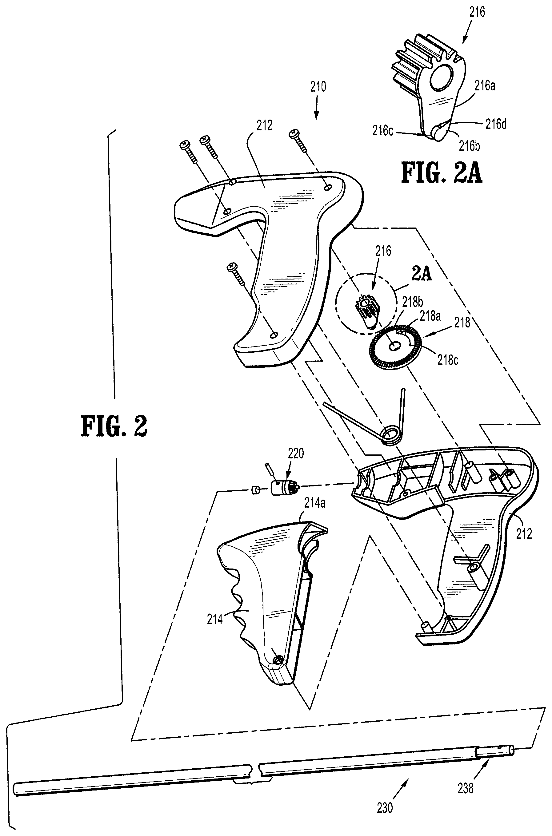
FIG. 2 is a perspective, assembly view of the surgical tacker instrument shown in FIG. 1;
FIG. 2a is an enlarged view of the area of detail indicated in FIG. 2;
FIG. 3 is a perspective, assembly view of an anchor retaining/advancing assembly of the surgical tacker instrument of FIG. 1;
FIG. 4 is an enlarged view of the area of detail indicated in FIG. 3;
FIG. 5 is a cross-sectional view of a portion of the anchor retaining/advancing assembly taken along line 5-5 in FIG. 1;
FIG. 6 is a cross-sectional view of a portion of the anchor retaining/advancing assembly taken along line 6-6 in FIG. 1;
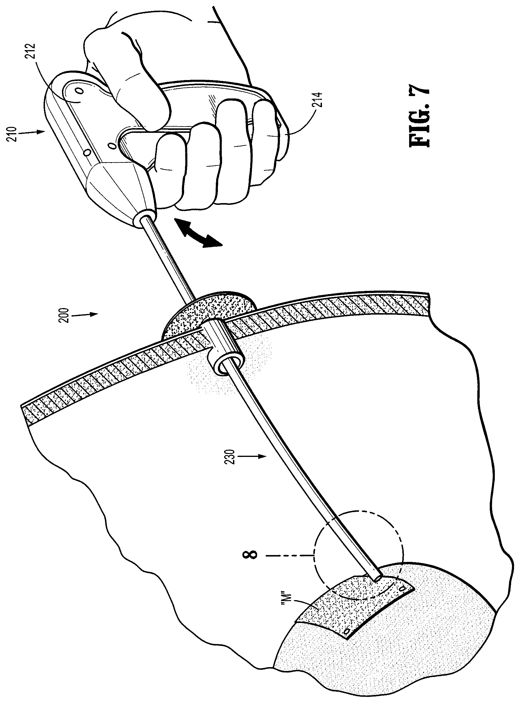
FIG. 7 is an in-situ view of the surgical tacker instrument of the present disclosure applying anchors to mesh and tissue;
FIG. 8 is an enlarged view of the area of detail indicated in FIG. 7 and further includes a partial cut-away view of a distal portion of the anchor retaining/advancing assembly;
FIG. 9 is a perspective, assembly view of another surgical tacker instrument in accordance with the present disclosure;
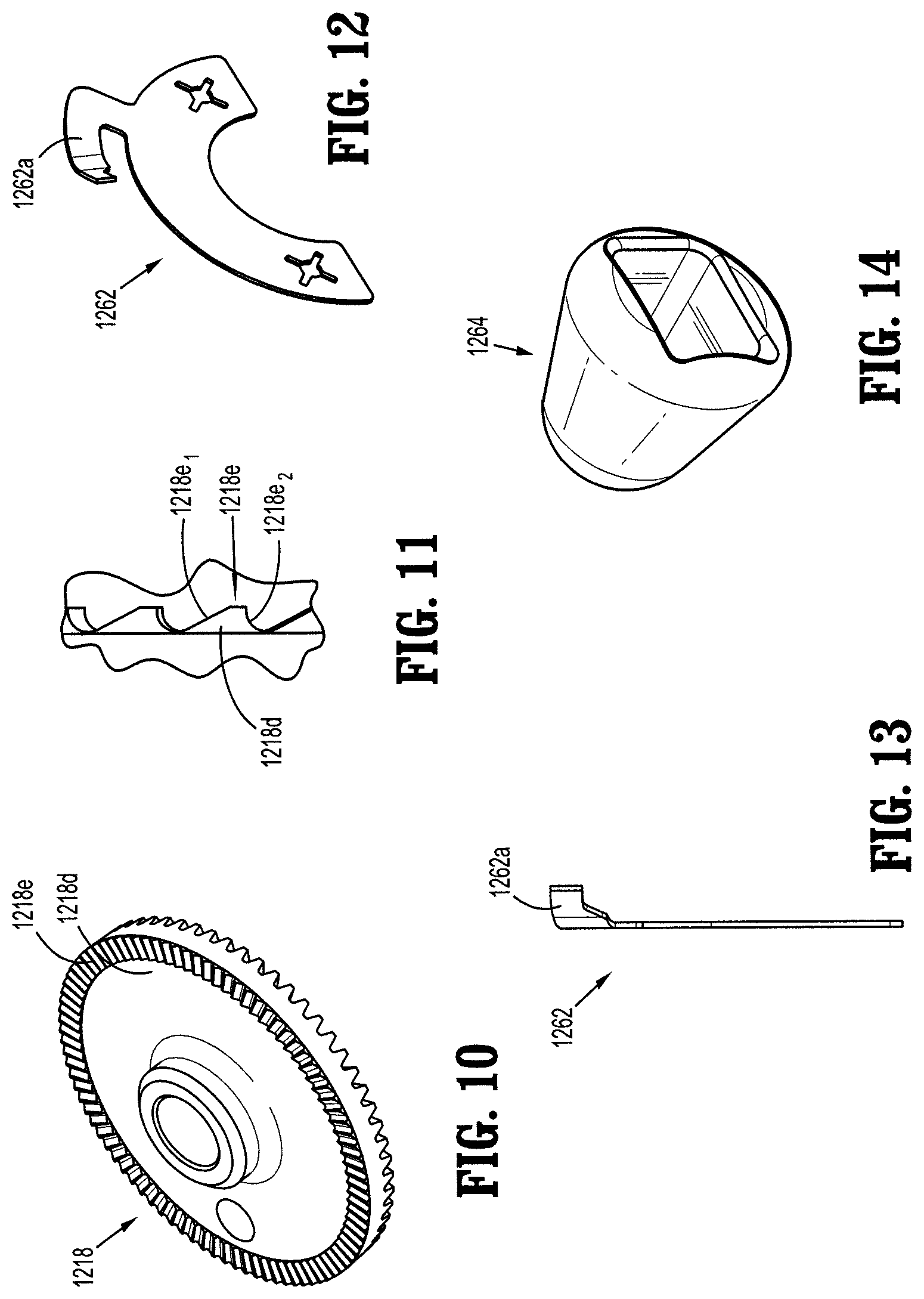
FIGS. 10-14 illustrate various features of the surgical tacker instrument of FIG. 9;
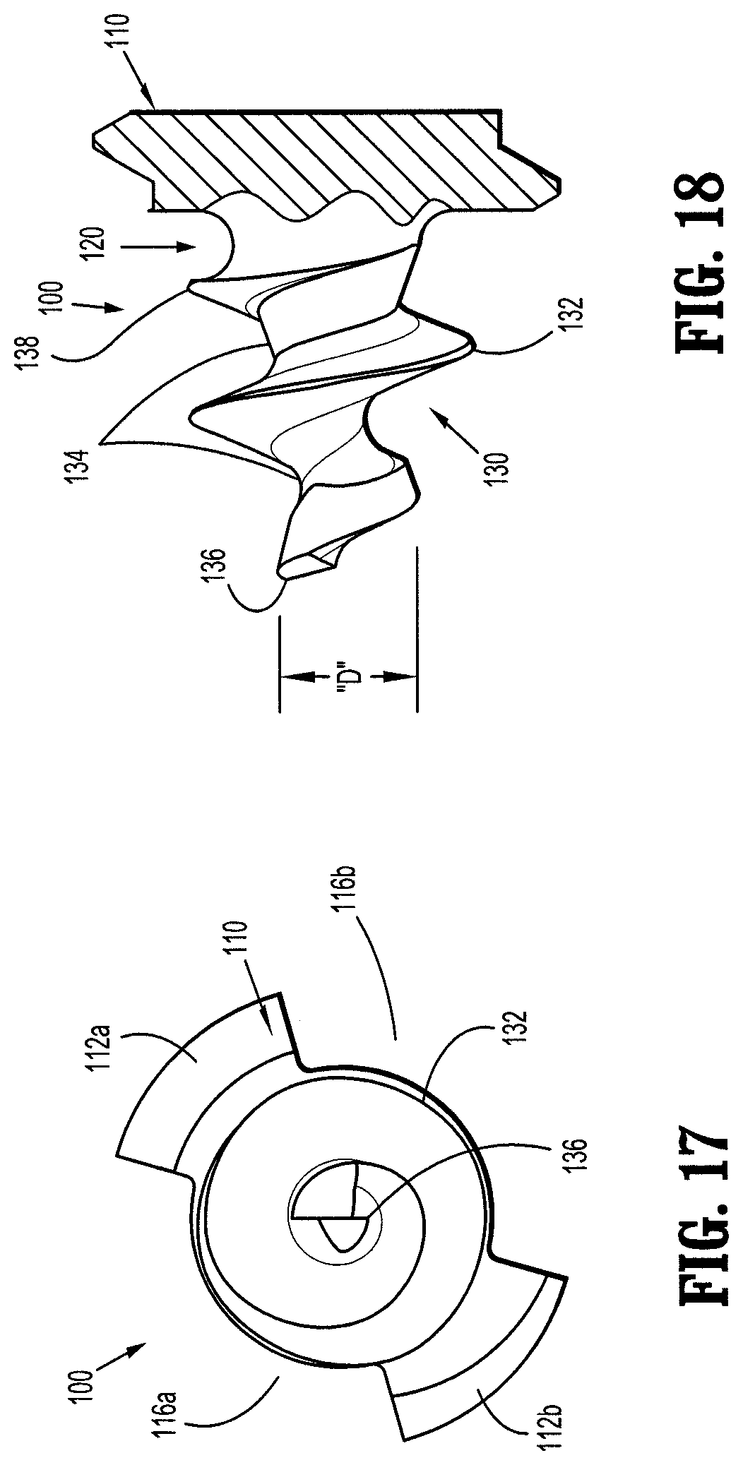
FIGS. 15-18 illustrate various views of an anchor for use in the surgical tacker instrument of FIGS. 1 and 9;
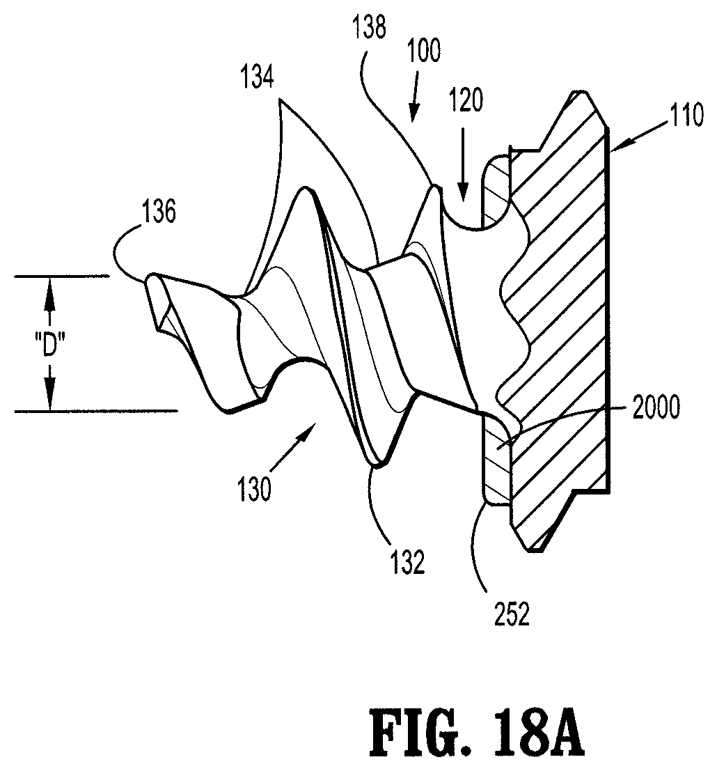
FIG. 18A illustrates an anchor including a solution disposed adjacent a distal surface of a head section; and
FIGS. 19-21 illustrate various embodiments of the surgical tacker instrument of FIGS. 1 and 9 including a solution therein.
DETAILED DESCRIPTION OF EMBODIMENTS
Embodiments of the presently disclosed surgical systems, apparatuses and/or devices are described in detail with reference to the drawings, in which like reference numerals designate identical or corresponding elements in each of the several views. As used herein the term "distal" refers to portions of the system, apparatus and/or device, or component thereof, that are farther from the user, while the term "proximal" refers to portions of the system, apparatus and/or device, or component thereof, that are closer to the user.
Referring to FIG. 1, a tacking instrument or tacker 200, for use in installing surgical fasteners in tissue is disclosed. Tacker 200 generally includes a handle assembly 210 and an anchor retaining/advancing assembly 230 extending from handle assembly 210 and configured to store and selectively release or fire a plurality of fasteners or anchors 100 therefrom.
As shown in FIGS. 1, 2 and 7, handle assembly 210 includes a handle housing 212 pivotably supporting a trigger 214. With specific reference to FIG. 2, trigger 214 defines a gear rack 214a formed thereon for operative engagement with a pinion gear 216 rotatably supported in handle housing 212. In disclosed embodiments, gear rack 214a and pinion gear 216 are dimensioned such that one complete squeeze of trigger 214 results in one complete revolution of pinion gear 216. As shown in FIG. 2a, pinion gear 216 includes an arm 216a extending radially therefrom and a cam or ramp 216b extending from arm 216a. Cam 216b includes a front end 216c having a height and tail end 216d tapering into arm 216a.
Handle assembly 210 further includes a bevel gear 218 operatively engaged with pinion gear 216. Bevel gear 218 defines an arcuate slot 218a formed therein for selectively receiving and engaging cam 216b of pinion gear 216. Slot 218a includes a front end wall 218b configured to engage front end 216c of cam 216b of pinion gear 216.
In use, as pinion gear 216 is rotated, upon the squeezing or actuation of trigger 214, front end 216c of cam 216b of pinion gear 216 engages front end wall 218a of slot 218b of bevel gear 218 resulting in concomitant rotation of bevel gear 218. Upon the completion of the actuation of trigger 214 and release thereof, pinion gear 216 rotates in an opposite direction and rear end 216d of cam 216b thereof cams out of slot 218b of bevel gear 218 and along a surface thereof. In disclosed embodiments, pinion gear 216 makes a complete revolution until front end 216c of cam 216b of pinion gear 216 re-engages or clears front end wall 218a of slot 218b of bevel gear 218. As such, cam 216b of pinion gear 216 re-enters slot 218b of bevel gear 218. Bevel gear 218 is maintained from rotating in an opposite direction, upon the opposite direction rotation of pinion gear 216, due to a coefficient of static friction between bevel gear 218 and a surface of handle housing 212 or an axis upon which bevel gear 218 is supported which will tend to maintain bevel gear 218 stationary.
With reference to FIGS. 2 and 3, handle assembly 210 further includes a pinion-bevel gear 220 having gear teeth 220a operatively engaged with gear teeth 218c formed on front end wall 218a of bevel gear 218. Pinion-bevel gear 220 is pinned to a proximal end of an inner tube 238 of anchor retaining/advancing assembly 230.
In use, as described above, upon squeezing of trigger 214, rotation of gear rack 214a causes pinion gear 216 to rotate. Rotation of pinion gear 216 results in rotation of bevel gear 218 and, in turn, rotation of pinion-bevel gear 220 and rotation of anchor retaining/advancing assembly 230.
Referring now to FIGS. 3-6, anchor retaining/advancing assembly 230 includes an outer tube 232 secured to and extending from handle housing 212, a stiffener tube 234 concentrically disposed within outer tube 232, a spiral or coil 236 fixedly disposed within stiffener tube 234 at a location proximate a distal end thereof, and an inner tube 238 rotatably disposed within coil 236.
Inner tube 238 includes a proximal end portion 240 and a distal end portion 242. Proximal end portion 240 of inner tube 238 extends into handle housing 212 and is secured to pinion-bevel gear 220 by a pin 222. Distal end portion 242 of inner tube 238 is slotted, defining a pair of tines 242a and a pair of channels 242b. Distal end portion 242 of inner tube 238 is capable of accepting a plurality of anchors 100 within inner tube 238. In particular, and with additional reference to FIG. 4, anchors 100 are loaded into anchor retaining/advancing assembly 230 such that the pair of opposing threaded sections 112a, 112b of anchors 100 extend through channels 242b of distal end portion 242 of inner tube 238 and are slidably disposed within the groove of coil 236, and the pair of tines 242a of distal end portion 242 of inner tube 238 are disposed within the pair of slotted sections 116 of anchors 100. It is envisioned that each anchor 100 is loaded into anchor retaining/advancing assembly 230 such that adjacent anchors 100 are not in contact with one another so as to not damage distal tips 136 thereof.
In operation, as inner tube 238 is rotated about its longitudinal axis, with respect to coil 236, the pair of tines 242a of inner tube 238 transmits the rotation to anchors 100 and advances anchors 100 distally due to head threads 114a, 114b of anchors 100 engaging with coil 236.
It is envisioned that coil 236 includes twenty-four threads per inch, and the overall length of each anchor 100 is between about 0.1 inches and about 0.3 inches (e.g., approximately equal to 0.203 inches). In such an embodiment, five full turns of inner tube 238 results in anchor 100 being advanced the approximate length of anchor (e.g., 0.203 inches).
Reference may be made to U.S. Provisional Patent Application No. 61/776,811, filed on Mar. 12, 2013, the entire contents of which are incorporated herein by reference, for a further detailed discussion of the construction and operation of tacker 200.
Reference may also be made to U.S. Provisional Patent Application No. 61/783,559, filed on Mar. 14, 2013, the entire contents of which are incorporated herein by reference, for a further detailed discussion of the construction and operation of a tacker which is configured and adapted for articulation and which may incorporate some of the principles of the present disclosure.
Turning now to FIGS. 9-14, a second embodiment of a tacker 1200 is shown. Tacker 1200 is substantially identical to tacker 200 and thus will only be described further herein to the extent necessary to identify differences in construction and/or operation.
As seen in FIGS. 9-14, tacker 1200 is provided with a ratchet mechanism 1260 which is configured to inhibit or prevent inner tube 1238 from backing-out after an anchor 100 has been at least partially driven into tissue. Ratchet mechanism 1260 includes a series of ratchet teeth 1218e formed on a rear end wall 1218d of a bevel gear 1218 (see FIG. 10). Further details of a ratchet mechanism are disclosed in commonly-owned U.S. patent application Ser. No. 10/123,490, the entire contents of which being hereby incorporated by reference herein.
With specific reference to FIG. 13, ratchet mechanism 1260 further includes a spring clip 1262 secured within handle assembly 1210. Spring clip 1262 includes a resilient finger 1262a configured for engagement with ratchet teeth 1218e formed on rear end wall 1218d of bevel gear 1218.
As shown in FIG. 11, each ratchet tooth 1218e includes a shallow angled side 1218e.sub.1 and a steep angled side 1218e.sub.2. In this manner, resilient finger 1262a of spring clip 1262 engages with ratchet teeth 1218e in such a manner that as bevel gear 1218 is rotated in a first direction resilient finger 1262a cams over shallow angled side 1218e.sub.1 of ratchet teeth 1218e. Also, if bevel gear 1218 is rotated in a second direction (opposite to the first direction), resilient finger 1262a stops against steep angled side 1218e.sub.2 of ratchet teeth 1218e thereby preventing or inhibiting bevel gear 1218 from rotating in the second direction. As such, any reverse rotation or "backing-out" of anchor 100 or inner tube 1238 (tending to cause bevel gear 1218 to rotate in the second direction), during a driving or firing stroke, is inhibited or prevented.
Referring now to FIGS. 9 and 14, tacker 1200 includes a plug 1264 disposed within inner tube 1238. In disclosed embodiments, plug 1264 is fabricated from a polymeric thermoplastic material (Monsanto Santoprene 271-87, available from Monsanto, Inc.) and dimensioned to create a fluid-tight seal within inner tube 1238. In this manner, escape or leakage of insufflations gas (and/or solution 2000, as discussed below) through inner tube 1238 is inhibited or prevented.
With reference to FIGS. 15-18, anchor 100 of the present disclosure, which is usable with tacker 200 and 1200, is shown. Anchor 100 includes a head section 110, a mesh retention section 120, and a threaded tissue-snaring section 130. Head section 110 includes a pair of opposing threaded sections 112a, 112b having respective head threads 114a, 114b, and a pair of opposing open or slotted sections 116a, 116b. A distal surface of head section 110 is formed onto or integral with a proximal end of mesh retention section 120.
Mesh retention section 120 of anchor 100 extends from and between a distal end of head section 110 and a proximal end of tissue-snaring section 130. Mesh retention section 120 functions to lock, anchor or otherwise retain a surgical mesh "M" on to anchor 100 when anchor 100 is screwed into the mesh to a depth past a proximal-most segment 138 of tissue-snaring thread 132. This is achieved because there is no thread located in mesh retention section 120 that would allow the mesh "M" to be unscrewed from anchor 100.
In the illustrated embodiments, mesh retention section 120 is generally cylindrical or conical in shape with a dimension transverse to its longitudinal axis that is smaller than the transverse dimension of head 110 and the transverse dimension of proximal-most segment 138 of tissue-snaring thread 138.
Threaded tissue-snaring section 130 of anchor 100 includes helical threads 132 formed onto a tapered truncated body section 134. A distal point or tip 136 defines the terminus of the distal most tissue-snaring thread 132.
As shown in FIG. 18, body section 134 of tissue-snaring section 130 is tapered, i.e., becoming smaller toward the distal end of threaded tissue-snaring section 130, and terminates, or truncates, distally prior to reaching an apex. Body section 134 includes a concave taper such that, for a given length, a minimum diameter body section 134 is defined upon truncation thereof which is approximately less than 0.01 inches, for example.
Anchor 100 includes a transverse dimension "D" (FIG. 18), of a distal-most thread in the threaded tissue-snaring section 130 which, in disclosed embodiments, is as large as design constraints will allow or approximately greater than 0.040 inches. It is envisioned that a small truncated body diameter and a large value of "D" minimizes tissue indentation. The tissue-snaring threads 132 terminate at distal tip 136, which is distal of the truncation point of body section 134. This geometry allows for ease of mesh penetration and minimizes indentation of the mesh into soft tissue as compared to a non-truncated body with tapered threads.
For a given force applied to a surgical mesh "M" by the surgeon, exerting a distal force on an applier 200, the larger the dimension "D," the less the pressure to cause indentation of an underlying tissue and surgical mesh "M."
Additionally, and with reference to FIGS. 18A-21, tackers 200 and 1200 of the present disclosure are usable with a solution 2000. While solution 2000 is at least usable with tackers 200 and 1200, only its use with tacker 200 is described herein. Solution 2000 may be a paste-like solution, a collagen-based solution, or a collagen paste solution, for example. For instance, solution 2000 may include porcine dermal collagen, which is sold by under the trade name Permacol.TM.. Here, solution 2000 may be an injectable Permacol.TM. or a Permacol.TM. paste with a viscosity tailored to the desired application. It is envisioned that Permacol.TM. sheets or other collagen sheets are cryomilled and prepared into suspensions by mixing the cryomilled power with water and/or saline. Here, the mixing concentration will determine the viscosity of the solution.
Solution 2000 is positioned within inner tube 238 and is dispensible from distal end 242 of inner tube 238, as discussed below. It is envisioned that solution 2000 is formulated to help reduce or prevent adhesion between the surgical mesh "M" and/or anchor 100 and a patient's tissue.
With specific reference to the embodiment illustrated in FIG. 19, the entirety of solution 2000 is disposed within an ampoule 2100. Ampoule 2100 is disposed within inner tube 238 and proximally of the proximal-most anchor 100. It is envisioned that ampoule 2100 includes at least one threaded portion 2110 on at least a portion of its perimeter. In the illustrated embodiment, ampoule 2100 includes two threaded portions 2110: one adjacent its proximal and one adjacent its distal end, but it is envisioned that ampoule 2100 includes more or fewer threaded portions 2110 disposed at any suitable location on or near ampoule 2100. Further, threaded portions 2110 may include any suitable number of threads and may be of any suitable length. As shown, threaded portion 2110 of ampoule 2100 engages coil 236, such that the rotation of bevel gear 220 (and, thus inner tube 238) to cause ejection of anchors 100 also causes ampoule 2100 to advance distally.
In this embodiment, a user initially ejects all anchors 100 from inner tube 238 (e.g., through mesh "M" and into tissue). Continued actuation of tacker 200 advances ampoule 2100 such that solution 2000 therein is able to be dispensed from distal end 242 of inner tube 238 onto/adjacent head section 110 of each anchor 100, for instance. It is envisioned that a distal tip 2120 of ampoule 2100 is frangible. Here, once distal tip 2120 is accessible (e.g., extends distally from inner tube 238), a user may rupture ampoule 2100 by causing distal tip 2120 to contact/depress against anchor 100, mesh "M," or tissue, for example, to cause solution 2000 from within ampoule 2100 to ooze/flow from ampoule 2100. The user can then position distal end 242 of inner tube 238 adjacent each anchor 100, individually, such that solution 2000 oozes/flows onto at least a portion of each anchor 100, for instance.
With specific reference to the embodiment illustrated in FIG. 20, solution 2000 is disposed proximally-adjacent, and in contact with, a proximal-facing surface 111 of head section 110 of anchor 100. Here, solution 2000 is mechanically engaged with, adhered to, or otherwise disposed on head section 110 of anchor 100 and is distally advanced along with anchor 100. In this embodiment, solution 2000 is either in direct contact with head section 110, or solution 2000 is enclosed in a puncturable impermeable or semi-permeable pouch, sac or membrane 250. It is envisioned that the viscosity of the solution 2000 that is used helps determine whether solution 2000 is in direct contact with head section 110 (solution 2000 has a relatively low viscosity) or whether solution 2000 is enclosed in a pouch 250 (solution 2000 has a relatively high viscosity).
When used in this embodiment, each anchor 100 is ejected from tacker 200 having its own pouch 250 of solution 2000 associated therewith, such that mesh retention section 120, and threaded tissue-snaring section 130 extend at least partially through mesh "M" and into tissue. In the embodiment where solution 2000 is in direct contact with head section 110, it is envisioned that solution 2000 flows/oozes at least partially around head section 110 substantially immediately after firing of anchor 100.
In the embodiment where solution 2000 is enclosed in a pouch 250, pouch 250 (including solution 2000 therein) remains on head section 110 of anchor 100 after anchor 100 is positioned in relation to mesh "M" and the patient. Subsequently, the user of tacker 200 may then use the distal end of anchor retaining/advancing assembly 230 to puncture pouch 250 to cause solution 2000 to be released adjacent anchor 100. Here, it is envisioned that the distal end of anchor retaining/advancing assembly 230 includes a suitable shape (e.g., a point-like) tip 243 (FIG. 20), or knurling, to facilitate puncturing of pouch 250. In this embodiment, it is envisioned that the user punctures each pouch 250 directly after its associated anchor 100 is emplaced through mesh "M" and into tissue. Alternatively, all anchors 100 can be ejected from inner tube 238 prior to pouches 250 being punctured. Any combination of these methods is also envisioned by the present disclosure.
Additionally, and with reference to FIG. 18A, it is envisioned for solution 2000 to be disposed on the distal surface of head section 110 of anchor 100. In such an embodiment, when solution 2000 is within a pouch 252 disposed on the distal surface of head section 110, it is envisioned that pouch automatically ruptures when anchor 100 is applied through mesh "M."That is, the distal surface of head section 110 compresses pouch 252 against the mesh "M," which results in pouch 252 rupturing, and the solution 2000 flowing/oozing from pouch 252 and around the periphery of head section 110 of anchor 100.
Referring to FIG. 21, another embodiment of tacker 200 is shown. Here, tacker 200 includes a plurality of anchors 100 within inner tuber 238, and also includes solution 2000 filling at least part of the remainder of the volume of inner tube 238. That is, in this embodiment, solution 2000 fills the voids between each anchor 100, proximally of the proximal-most anchor 100, distally of the distal-most anchor 100 and/or between each adjacent anchor 100. Here, when a user actuates handle assembly 120 to eject anchors 100, solution 2000 is automatically dispensed as well. It is envisioned that solution 2000 and anchors 100 are positioned within inner tube 238 during assembly of tacker 200. For example, inner tuber 238 may be injected with a first dosage of solution 2000, loaded with a first anchor 100, injected with a second dosage of solution 2000, followed by a second anchor 100, etc.
Additionally, methods using the disclosed tacker 200, 1200 including solution 2000, are also envisioned and part of the present disclosure.
While the present disclosure relates to anchors 100 and solution 2000 used with a manually-actuatable tacker 200, 1200, it is envisioned that anchors 100 and/or solution 2000 are usable with a powered tacker instrument, such as that described in U.S. Pat. No. 7,931,660 to Aranyi, et al., the entire contents of which being hereby incorporated by reference herein.
It will be understood that various modifications may be made to the embodiments disclosed herein. For example, the disclosed tacker devices may be configured so that the anchor retaining/advancing assembly is removable, and or disposable, from the associated handle assembly. Therefore, the above description should not be construed as limiting, but merely as exemplifications of particular embodiments. Those skilled in the art will envision other modifications within the scope and spirit of the claims appended hereto.
* * * * *
D00000
D00001
D00002
D00003
D00004
D00005
D00006
D00007
D00008
D00009
D00010
D00011
D00012

D00013

XML
uspto.report is an independent third-party trademark research tool that is not affiliated, endorsed, or sponsored by the United States Patent and Trademark Office (USPTO) or any other governmental organization. The information provided by uspto.report is based on publicly available data at the time of writing and is intended for informational purposes only.
While we strive to provide accurate and up-to-date information, we do not guarantee the accuracy, completeness, reliability, or suitability of the information displayed on this site. The use of this site is at your own risk. Any reliance you place on such information is therefore strictly at your own risk.
All official trademark data, including owner information, should be verified by visiting the official USPTO website at www.uspto.gov. This site is not intended to replace professional legal advice and should not be used as a substitute for consulting with a legal professional who is knowledgeable about trademark law.