Reference signal distribution in multi-module systems
Chayat , et al. October 13, 2
U.S. patent number 10,804,954 [Application Number 16/704,009] was granted by the patent office on 2020-10-13 for reference signal distribution in multi-module systems. This patent grant is currently assigned to VAYYAR IMAGING LTD.. The grantee listed for this patent is VAYYAR IMAGING LTD.. Invention is credited to Naftali Chayat, Jonathan Rosenfeld.


| United States Patent | 10,804,954 |
| Chayat , et al. | October 13, 2020 |
Reference signal distribution in multi-module systems
Abstract
Systems of multiple transmitters and multiple receivers, allowing receivers to identify the transmitters from which reference signals originate. Identification is according to frequency offset patterns based on transmitter and local oscillator frequencies, and is particularly suitable in radio-frequency integrated-circuit devices and MIMO radar systems.
| Inventors: | Chayat; Naftali (Kfar Saba, IL), Rosenfeld; Jonathan (Ramat Hasharon, IL) | ||||||||||
|---|---|---|---|---|---|---|---|---|---|---|---|
| Applicant: |
|
||||||||||
| Assignee: | VAYYAR IMAGING LTD. (Yehud,
IL) |
||||||||||
| Family ID: | 1000005115156 | ||||||||||
| Appl. No.: | 16/704,009 | ||||||||||
| Filed: | December 5, 2019 |
Prior Publication Data
| Document Identifier | Publication Date | |
|---|---|---|
| US 20200119762 A1 | Apr 16, 2020 | |
Related U.S. Patent Documents
| Application Number | Filing Date | Patent Number | Issue Date | ||
|---|---|---|---|---|---|
| 16008068 | Jun 14, 2018 | ||||
| 15473884 | Mar 30, 2017 | 10020836 | |||
| PCT/IL2015/050973 | Sep 24, 2015 | ||||
| 62057286 | Sep 30, 2014 | ||||
| Current U.S. Class: | 1/1 |
| Current CPC Class: | H04B 1/48 (20130101); H04B 17/12 (20150115); H04B 17/21 (20150115); H04B 17/14 (20150115) |
| Current International Class: | H04B 1/48 (20060101); H04B 17/21 (20150101); H04B 17/14 (20150101); H04B 17/12 (20150101) |
References Cited [Referenced By]
U.S. Patent Documents
| 8705654 | April 2014 | Khlat et al. |
| 2002/0039889 | April 2002 | Boos |
| 2003/0038618 | February 2003 | Gumm |
| 2005/0090212 | April 2005 | Earls et al. |
| 2006/0121871 | June 2006 | Kim |
| 2009/0116374 | May 2009 | Henriksson et al. |
| 2009/0315761 | December 2009 | Walter |
| 2010/0056083 | March 2010 | Kim et al. |
| 2011/0271155 | November 2011 | Tran |
| 2012/0309328 | December 2012 | Morrison et al. |
| 2000-013255 | Jan 2000 | JP | |||
| 2003-273818 | Sep 2003 | JP | |||
Other References
|
International Search Report for PCT Application No. PCT/IL2015/050973 dated Jan. 19, 2017. cited by applicant. |
Primary Examiner: Vo; Nguyen T
Attorney, Agent or Firm: Cohen; Mark Cohen; Pearl Zedek Latzer Baratz
Parent Case Text
This application is a Continuation Application of U.S. patent application Ser. No. 16/008,068, filed Jun. 14, 2018, titled `Reference signal distribution in multi-module systems`, which is a Divisional Application of U.S. patent application Ser. No. 15/473,884, filed Mar. 30, 2017, titled `Reference signal distribution in multi-module systems`, which is a continuation of PCT International Application No. PCT/IL2015/050973, International Filing Date Sep. 24, 2015, claiming priority of U.S. Provisional Patent Application No. 62/057,286, filed Sep. 30, 2014.
Claims
What is claimed is:
1. A radio-frequency (RF) system comprising: a plurality of transmitters, each transmitter having a predetermined transmitting frequency, wherein the difference between transmitting frequencies of any two transmitters of the plurality of transmitters is a transmitter frequency offset which is substantially an integer multiple of a predetermined df coefficient, and for any selected transmitter of the plurality of transmitters, the frequency differences between the transmitting frequency of the selected transmitter and the transmitting frequency of every other transmitter of the plurality have distinct absolute values.
2. The radio-frequency (RF) system of claim 1, further comprising at least one receiver having a predetermined local oscillator frequency.
3. The radio-frequency (RF) system of claim 2, further comprising a plurality of receivers, each receiver of which has a respective predetermined local oscillator frequency.
4. The radio-frequency (RF) system of claim 3, wherein each receiver local oscillator frequency is the same as a transmitting frequency of a transmitter of the plurality of transmitters, and wherein each receiver is operative to receive a signal input and a local oscillator input.
5. The radio-frequency (RF) system of claim 4, wherein a receiver of the plurality of receivers is a reference signal receiver.
6. The radio-frequency (RF) system of claim 5, wherein the transmitting frequency of at least one transmitter of the plurality of transmitters is provided to a respective reference signal receiver.
7. The radio-frequency (RF) system of claim 3, wherein the RF system is a multiple input/multiple output (MIMO) radar system.
8. The multiple input/multiple output (MIMO) radar system of claim 7, wherein each receiver local oscillator frequency is the same as a transmitting frequency of a transmitter of the plurality of transmitters, and wherein each receiver is operative to receive a signal input and a local oscillator input.
9. The multiple input/multiple output (MIMO) radar system of claim 8, wherein a receiver of the plurality of receivers is a reference signal receiver.
10. The multiple input/multiple output (MIMO) radar system of claim 9, wherein the transmitting frequency of at least one transmitter of the plurality of transmitters is provided to a respective reference signal receiver.
11. The multiple input/multiple output (MIMO) radar system of claim 7, wherein the plurality of transmitters consists of four transmitters, and wherein the transmitter frequency offsets are respectively 0, 1, 3, and 4 times the predetermined df coefficient.
12. The multiple input/multiple output (MIMO) radar system of claim 7, wherein the plurality of transmitters consists of eight transmitters, and wherein the transmitter frequency offsets are respectively 0, 1, 3, 4, 9, 10, 12 and 13 times the predetermined df coefficient.
13. The radio-frequency (RF) system of claim 1, wherein the plurality of transmitters consists of four transmitters, and wherein the transmitter frequency offsets are respectively 0, 1, 3, and 4 times the predetermined df coefficient.
14. The radio-frequency (RF) system of claim 1, wherein the plurality of transmitters consists of eight transmitters, and wherein the transmitter frequency offsets are respectively 0, 1, 3, 4, 9, 10, 12 and 13 times the predetermined df coefficient.
Description
FIELD
The present invention is directed to multi-module radio-frequency calibration, in particular to the calibration of radio frequency integrated circuits (RFIC).
BACKGROUND
Multi-module systems typically require sharing of frequency and phase reference signals for real-time calibration. In such systems, it is desirable to measure transmission characteristics between arbitrarily-selected ports of the modules. For example, in a phased-array radar system it is necessary to know the relative phase characteristics at the respective antennas in order to be able to direct a phased beam in a particular direction. In another example, multiple input/multiple output (MIMO) radar systems require referencing received signals to one another.
Under ideal conditions, measurement of reference signals is generally stratightforward. When transmission losses are high, however, signal leakage among module ports interferes with reference measurement. For example, when making multi-port measurements with a vector network analyzer (VNA) there is typically some signal leakage between the VNA's ports, which limits the dynamic range of the measurements. This problem is particularly pronounced in the case of a single RFIC, where the isolation is limited because of the small inter-port distances and the inherently-restricted isolation of the RFIC, the package, and the printed circuit board (PCB). Here, the likely limit for isolation is on the order of 50 dB, achieved between the most distantly-separated RFIC ports.
A known improvement to the above-described isolation problem is to use a separate shielded RFIC for each port. In this way, the signal transmitted to the device (or medium) under test (hereinafter denoted as "DUT") has a significantly better isolation, and only the signal passing through the DUT reaches the other RFIC. Unfortunately, however, this introduces the problem of providing a phase reference to the mated RFIC. RFICs may have distinct synthesizers, so the phase of a signal from one RFIC downconverted within another RFIC cannot be directly measured--only comparative measurements can be made. This requires that a sample of the reference signal be provided to the receiving RFIC. The straightforward approach for providing the reference is to bring a sample of the transmitted signal to the receiving RFIC via a receiving port, and then measure the phase difference between the signal from the DUT and the reference signal from the transmitting RFIC. However, bringing a signal at the test frequency can contaminate the signal from the DUT, because the receiving RFIC has limited isolation. The problem could be lessened by weakening the reference signal, but doing so also reduces measurement accuracy because of the degraded signal-to-noise ratio of the reference.
Under the conditions and restrictions described above, it would be desirable to have methods for reducing or eliminating signal leakage; reducing or eliminating the affects of signal leakage on measurements; and making accurate measurements in spite of signal leakage. These goals are met by embodiments of the present invention.
SUMMARY
Various embodiments of the present invention provide efficient and ordered distribution of reference signals in RF systems having multiple receivers and transmitters. These embodiments provide reference sharing among the different ports of the modules, in configurations including, but not limited to: a star coupler featuring all-to-all reference coupling; and neighboring module-to-module reference sharing.
In addition, certain embodiments of the present invention provide isolation for reference signals that are being shared among modules, by furnishing each reference signal with a unique signature, allowing individual reference signals to be identified and separated as necessary throughout the system. According to various embodiments of the invention, signatures can be applied via frequency-shifting or binary phase-shift encoding.
Therefore, according to an embodiment of the present invention there is provided a radio-frequency transmitter-receiver system including: (a) a transmitter for transmitting a transmitted signal at a transmission frequency; (b) a receiver for receiving the transmitted signal as a received transmitted signal, wherein: (c) the receiver includes a local oscillator having a local oscillator signal at a local oscillator frequency, for downconverting the received transmitted signal from the transmission frequency to an intermediate frequency as a receiver intermediate frequency signal; (d) a transmitter downconverter associated with the transmitter, for downconverting the transmitted signal from the transmission frequency to the intermediate frequency as a transmitter intermediate frequency signal; (e) a reference signal path from the local oscillator to the transmitter downconverter, for conveying the local oscillator signal from the local oscillator to the transmitter downconverter; and (f) a phase comparator, for measuring a phase difference between the receiver intermediate frequency signal and the transmitter intermediate frequency signal.
In addition, according to another embodiment of the present invention, there is also provided a method for calibrating a radio-frequency transmitter-receiver system having a transmitter with a transmitted signal, a receiver with a local oscillator signal and a receiver intermediate frequency signal, and a transmitter downconverter, the method including: (a) downconverting the transmitted signal via the downconverter to a transmitter intermediate frequency signal according to the local oscillator signal; (b) measuring a phase difference between the receiver intermediate frequency signal and the transmitter intermediate frequency signal; and (c) calibrating the transmitter-receiver system according to the phase difference.
BRIEF DESCRIPTION OF THE DRAWINGS
The subject matter disclosed may best be understood by reference to the following detailed description when read with the accompanying drawings in which:
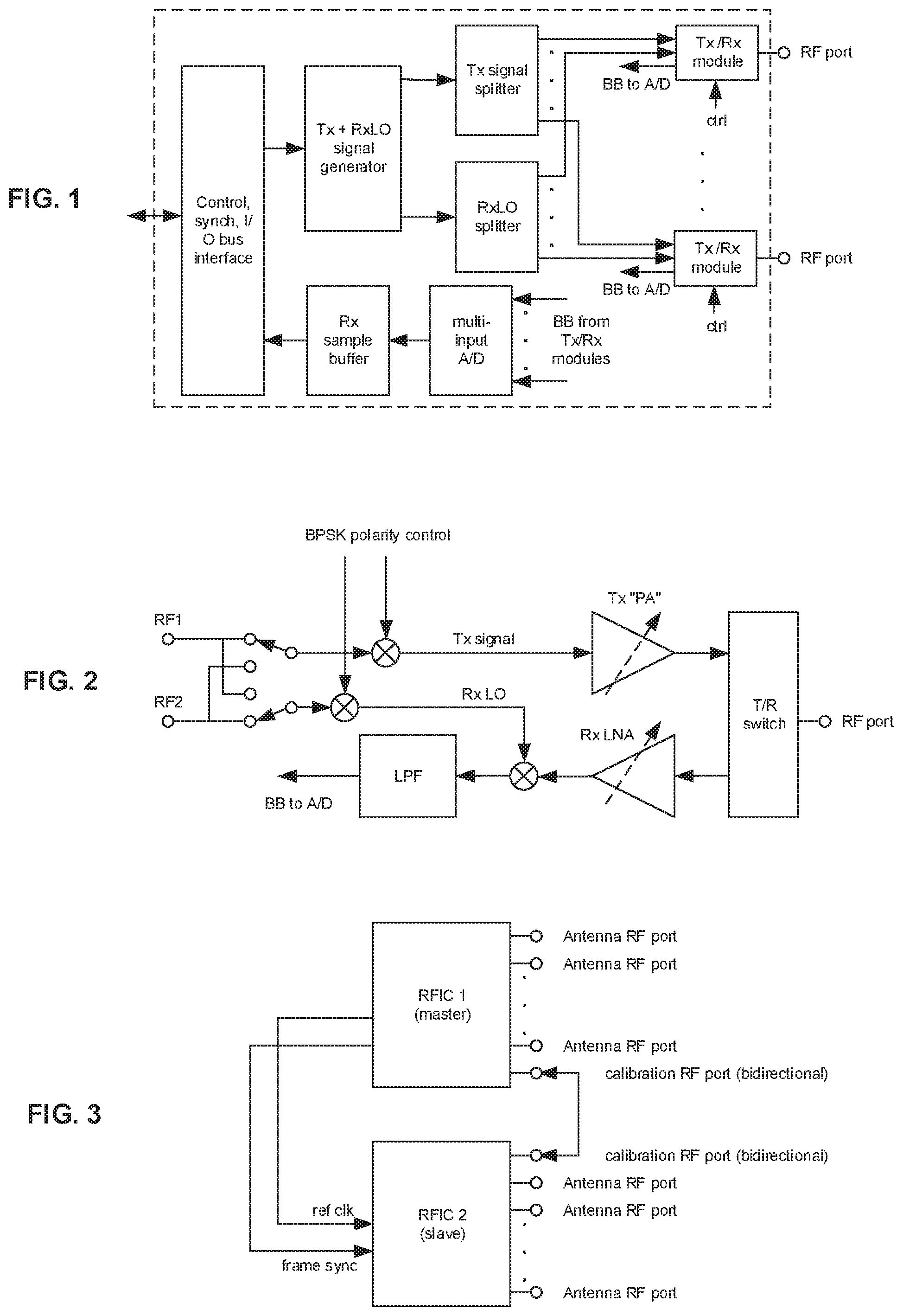
FIG. 1 is a top-level block diagram of a radio-frequency integrated circuit (RFIC).
FIG. 2 is a block diagram of an exemplary transmit/receive module.
FIG. 3 is a block diagram of a system of two RFICs.
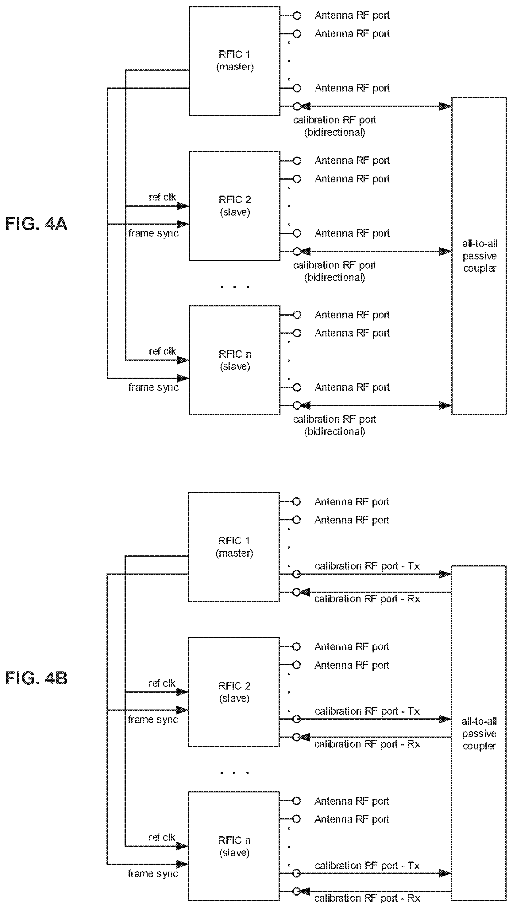
FIG. 4A is a block diagram of a multi-module RFIC system having bidirectional ports used for calibration.
FIG. 4B is a block diagram of a multi-module RFIC system having dedicated ports used for calibration.
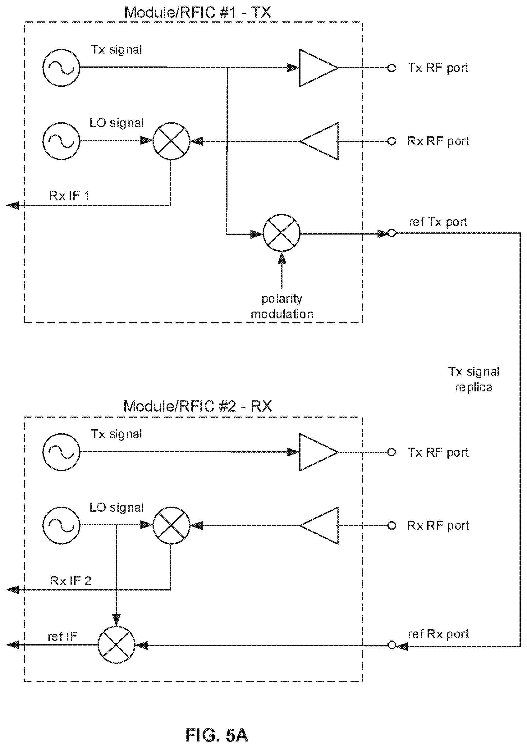
FIG. 5A is a block diagram showing a reference signal sent from a transmitting module to a receiving module.
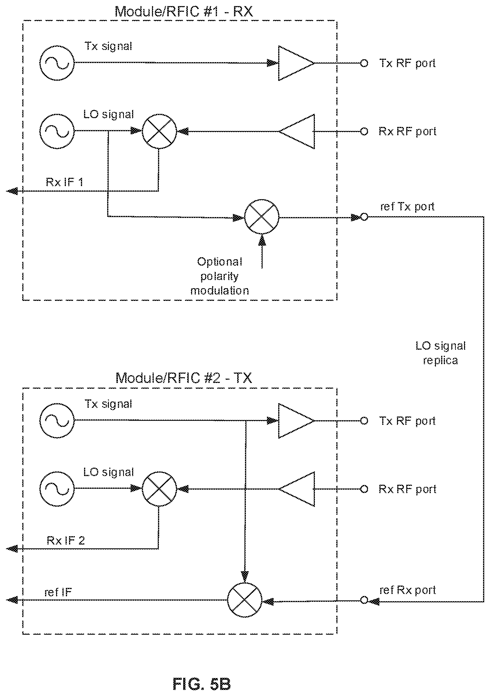
FIG. 5B is a block diagram showing a reference signal sent from a receiving module to a transmitting module.
FIG. 6A is a schematic diagram of a simplified all-to-all symmetric star coupler.
FIG. 6B is a block diagram of a symmetric all-to-all reference signal distributor.
FIG. 6C is a block diagram of an exemplary 8-port all-to-all Butler/Hadamard coupler.
For simplicity and clarity of illustration, elements shown in the figures are not necessarily drawn to scale, and the dimensions of some elements may be exaggerated relative to other elements. In addition, reference labels may be repeated among the figures to indicate corresponding or analogous elements.
DETAILED DESCRIPTION
Certain embodiments of the present invention provide a reference signal that is distinct from the transmitted signal, so that leakage of the reference signal into the signal from the DUT does not cause a measurement error. In some of these embodiments, the reference signal is mathematically orthogonal to the transmitted signal. According to a related embodiment, orthogonality is attained by frequency offsetting; according to another related embodiment, orthogonality is attained by binary phase shift keying (BSPK), either fast or slow.
In one embodiment, the transmitting RFIC conveys the reference to other RFICs using BPSK (a non-limiting example of which uses 1 MHz modulation). The signal to the DUT is sent as a continuous wave (CW). As a result, the reference signal contains no spectral component at 0 Hz (DC). The receiving RFICs receive both the CW signal from the DUT (on one of the ports) and the BPSK-modulated signal (on another port). The reference signal is BPS K-demodulated, downconverted and integrated in software so as to obtain the reference phasor. Because the reference and the DUT signals are orthogonal, there is no mutual contamination. The BPSK modulation can be implemented through BPSK toggling at the TR module sending the reference (though it can introduce noise)--modulation through arbitrary waveform generation (AWG) is not an option since RFIC.sub.1 is dedicated to generating the transmitted CW signal and RFIC.sub.2 is dedicated to generating the CW receive signal. In an alternative embodiment, BPSK modulation is performed on the local oscillator (LO) signal in the transmitting module receiving the reference.
In another embodiment of the present invention, the transmitting chip conveys the reference to the other chips using BPSK modulation on a snapshot-by-snapshot basis. One snapshot is taken with the reference sent at regular polarity and the other at opposite polarity. The two snapshots are summed for the regular signal and subtracted for the reference signal. The snapshot can be halved in time to maintain same resolution bandwidth (RBW). In a related embodiment, BPSK modulation is implemented through software polarity toggling at the transmitting module (software-based toggling avoids injecting noise).
In a further embodiment, the transmitting RFIC sends to the receiving RFIC the receive local oscillator (RX_LO) as a reference rather than the transmitted signal. The receiving RFIC is configured to a RX_LO' frequency which is offset from both the transmitted signal and the RX_LO frequency. In a non-limiting example, the transmitting frequency is 10.010 GHz, RX_LO is 10.008 GHz and RX_LO' is 10.007 GHz. Then the transmitting RFIC will receive the transmission at 2 MHz, while the receiving RFIC will receive the transmission at 3 MHz and RX_LO at 1 MHz by digitally downconverting the 3 MHz with the received 1 MHz downconverted RX_LO signal. In practice, this is done by multiplying the downconverted 3 MHz samples with conjugate of downconverted 1 MHz samples. Because there is no signal conveyed to the receiving RFIC at the transmitting frequency, the measurement of the signal from the DUT is not contaminated by leakage.
In the above example, if RX_LO' is higher in frequency than RX_LO (e.g. LO_RX is 10.007 GHz and RX_LO' is 10.008 GHz) the reference is converted to a "negative frequency" ("-1 MHz"), and during the reconstruction no conjugation is needed.
In respective related embodiments, the above cases extend to arbitrary numbers of multiple receive RFICs. Since only one RFIC transmits at any given time, the processed reference signals are distributed to the other RFICs.
In further embodiments of the present invention, simultaneous transmission is done from multiple RFICs. In a related embodiment, staggered frequencies (by an order of RBW) are used, where the RBW frequency offset does not unsatisfactorily degrade the measurement.
Other embodiments provide BPSK manipulation of the transmitted signals in cases where multiple reference signals need to be distributed. In a related embodiment, BPSK encoding (such as by Hadamard matrix rows) of transmission signals are used to distinguish between the multiple reference signals. In this embodiment, the encodings of the references signals of the RFICs are mutually orthogonal and thus distinguishable. The BPSK code [1 1 . . . 1] is not used, to avoid contaminating the transmitted signal.
A further related embodiment provides multiple RX_LO frequencies, so that the mixed frequency differences are distinct. In a non-limiting example, 4 RFICs with RX_LO frequencies of F.sub.0, F.sub.0+df, F.sub.0+3df and F.sub.0+4df, respectively, can be used. The df coefficients 0, 1, 3, and 4 are chosen to avoid overlaps caused by the oscillator.+-.mixing. That is, RFIC.sub.1 will receive at frequencies +df, +3df and +4df, RFIC.sub.2 will receive the references at -df, +2df and +3df, etc., such that all absolute values are distinct. The scheme can be further extended--for example for 8 RFICs the frequency offsets could be [0,1,3,4,9,10,12,13]df. This technique can be used in conjunction with using the same frequency for transmission and as a local oscillator in each module (such as in FMCW, CW or stepped CW radar), so that each module can receive all the rest of the modules and distinguish between their signals, both in the reference path and in the over-the-air path.
Another embodiment provides orthogonal multiplexing for multi-module operation when several modules are transmitting. This embodiment achieves not only the benefits of reference signal isolation, but also a time- and memory-efficient multiple operation per sweep, such as for a multistatic radar application.
An additional embodiment of the present invention further provides a solution to a problem which arises when demodulating a received signal with a signal derived from the same LO as the transmitted signal. Any spur or artifact situated about the LO contributes to an effective noise floor. Examples of such artifacts include: the image components associated with quadrature modulation imbalance and reference spurs situated about the LO. According to this embodiment of the invention, the problem may be avoided in the multi-module case by shifting the LO of each module relative to all others, thus also shifting the associated artifacts.
A further embodiment of the present invention circumvents the need to send a replica of the transmitted signal to the receiving module. Conveying a replica of the transmitted signal to the receiving module allows characterizing the relative phase between the reference signal path and the signal path through the device or medium under test by measuring the relative phase of intermediate frequency signals resulting from the mixing of the received signal with a local oscillator. However, any leakage of the replica of the transmitted signal in the receiver can contaminate the received signal. A related embodiment of the present invention avoids this problem by avoiding sending a replica of the transmitted signal to the receiving module. Instead, this embodiment provides a replica of the receiving module's local oscillator (LO) back to the transmitting module. The transmitting module then locally mixes (via a dedicated downconverter) the receiving module's LO with the transmitted signal, thereby generating an intermediate frequency (IF) at the transmitter. This transmitter intermediate frequency signal is indicative of the relative phase between the transmitted signal and the receiver's intermediate frequency signal. By performing this operation in the transmitting module rather than in the receiving module, this embodiment guarantees that only the transmitted signal passing through the DUT reaches the receiving module, and that no other signal at same frequency is present there.
* * * * *
D00000
D00001
D00002
D00003
D00004
D00005
XML
uspto.report is an independent third-party trademark research tool that is not affiliated, endorsed, or sponsored by the United States Patent and Trademark Office (USPTO) or any other governmental organization. The information provided by uspto.report is based on publicly available data at the time of writing and is intended for informational purposes only.
While we strive to provide accurate and up-to-date information, we do not guarantee the accuracy, completeness, reliability, or suitability of the information displayed on this site. The use of this site is at your own risk. Any reliance you place on such information is therefore strictly at your own risk.
All official trademark data, including owner information, should be verified by visiting the official USPTO website at www.uspto.gov. This site is not intended to replace professional legal advice and should not be used as a substitute for consulting with a legal professional who is knowledgeable about trademark law.