Waveplate lenses and methods for their fabrication
Tabirian , et al. October 13, 2
U.S. patent number 10,802,302 [Application Number 16/169,717] was granted by the patent office on 2020-10-13 for waveplate lenses and methods for their fabrication. This patent grant is currently assigned to Beam Engineering for Advanced Measurements Co., The United States of America as Represented by the Secretary of the Army. The grantee listed for this patent is Beam Engineering for Advanced Measurements Co., U.S. Government as Represented by the Secretary of the Army. Invention is credited to Brian Kimball, Svetlana Serak, Diane Steeves, Nelson Tabirian.


View All Diagrams
| United States Patent | 10,802,302 |
| Tabirian , et al. | October 13, 2020 |
Waveplate lenses and methods for their fabrication
Abstract
The invention provides for lenses fabricated as planar thin film coatings with continuous structure. The lensing action is due to optical axis orientation modulation in the plane of the lens. The lenses of the current invention are fabricated using photoalignment of a liquid crystal polymer wherein the polarization pattern of radiation used for photoalignment is obtained by propagating the light through an optical system comprising a shape-variant nonlinear spatial light polarization modulators.
| Inventors: | Tabirian; Nelson (Winter Park, FL), Serak; Svetlana (Oviedo, FL), Steeves; Diane (Franklin, MA), Kimball; Brian (Shrewsbury, MA) | ||||||||||
|---|---|---|---|---|---|---|---|---|---|---|---|
| Applicant: |
|
||||||||||
| Assignee: | Beam Engineering for Advanced
Measurements Co. (Orlando, FL) The United States of America as Represented by the Secretary of the Army (Washington, DC) |
||||||||||
| Family ID: | 1000005112919 | ||||||||||
| Appl. No.: | 16/169,717 | ||||||||||
| Filed: | October 24, 2018 |
Prior Publication Data
| Document Identifier | Publication Date | |
|---|---|---|
| US 20190113777 A1 | Apr 18, 2019 | |
Related U.S. Patent Documents
| Application Number | Filing Date | Patent Number | Issue Date | ||
|---|---|---|---|---|---|
| 14214375 | Mar 14, 2014 | 10114239 | |||
| 13860834 | Apr 11, 2013 | ||||
| 12662525 | Apr 21, 2010 | ||||
| 61801251 | Mar 15, 2013 | ||||
| Current U.S. Class: | 1/1 |
| Current CPC Class: | G02F 1/134309 (20130101); G02F 1/133788 (20130101); G02F 1/0136 (20130101); G02F 1/133365 (20130101) |
| Current International Class: | G02F 1/1333 (20060101); G02F 1/1337 (20060101); G02F 1/1343 (20060101); G02F 1/01 (20060101) |
References Cited [Referenced By]
U.S. Patent Documents
| 2435616 | February 1948 | Vittum |
| 3721486 | March 1973 | Bramley |
| 3897136 | July 1975 | Bryngdahl |
| 4160598 | July 1979 | Firester et al. |
| 4301023 | November 1981 | Schuberth |
| 4698816 | October 1987 | Chun |
| 4956141 | September 1990 | Allen |
| 4983332 | January 1991 | Hahn |
| 5032009 | July 1991 | Gibbons |
| 5042950 | August 1991 | Salmon, Jr. |
| 5047847 | September 1991 | Toda |
| 5100231 | March 1992 | Sasnett et al. |
| 5142411 | August 1992 | Fiala |
| 5150234 | September 1992 | Takahashi |
| 5218610 | June 1993 | Dixon |
| 5321539 | June 1994 | Hirabayashi |
| 5325218 | June 1994 | Willett |
| 5446596 | August 1995 | Mostrorocco |
| 5619325 | April 1997 | Yoshida |
| 5621525 | April 1997 | Vogeler et al. |
| 5712721 | January 1998 | Large |
| 5895422 | April 1999 | Hauber |
| 5903330 | May 1999 | Funschilling |
| 5907435 | May 1999 | Ang |
| 5989758 | November 1999 | Komatsu |
| 6091471 | July 2000 | Kim |
| 6107617 | August 2000 | Love et al. |
| 6139147 | October 2000 | Zhang |
| 6170952 | January 2001 | La Haye et al. |
| 6191880 | February 2001 | Schuster |
| 6219185 | April 2001 | Hyde |
| 6320663 | November 2001 | Ershov |
| 6373549 | April 2002 | Tombling et al. |
| 6452145 | September 2002 | Graves et al. |
| 6551531 | April 2003 | Ford |
| 6678042 | January 2004 | Tabirian et al. |
| 6728049 | April 2004 | Tabirian et al. |
| 6792028 | September 2004 | Cook |
| 6911637 | June 2005 | Vorontsov et al. |
| 7048619 | May 2006 | Park |
| 7094304 | August 2006 | Nystrom |
| 7095772 | August 2006 | Delfyett et al. |
| 7196758 | March 2007 | Crawford |
| 7319566 | January 2008 | Prince |
| 7324286 | January 2008 | Glebov |
| 7450213 | November 2008 | Kim et al. |
| 7482188 | January 2009 | Moon |
| 7764426 | July 2010 | Lipson |
| 8045130 | October 2011 | Son |
| 8077388 | December 2011 | Gerton |
| 8264623 | September 2012 | Marrucci |
| 8520170 | August 2013 | Escuti |
| 8582094 | November 2013 | Shortt |
| 8643822 | February 2014 | Tan et al. |
| 8937701 | January 2015 | Rossini |
| 8982313 | March 2015 | Escuti et al. |
| 9535258 | January 2017 | Whiteaker |
| 9541772 | January 2017 | De Sio et al. |
| 9557456 | January 2017 | Tabirian et al. |
| 9592116 | March 2017 | De Sio et al. |
| 9617205 | April 2017 | Tabirian et al. |
| 9658512 | May 2017 | Tabirian et al. |
| 9715048 | July 2017 | Tabirian et al. |
| 9753193 | September 2017 | Tabirian et al. |
| 9976911 | May 2018 | Tabirian et al. |
| 9983479 | May 2018 | Tabirian et al. |
| 10031424 | July 2018 | Tabirian et al. |
| 10036886 | July 2018 | Tabirian et al. |
| 10075625 | September 2018 | Tabirian et al. |
| 10107945 | October 2018 | Tabirian et al. |
| 10114239 | October 2018 | Tabirian et al. |
| 10120112 | November 2018 | Tabirian et al. |
| 10185182 | January 2019 | Tabirian |
| 10191191 | January 2019 | Tabirian et al. |
| 10191296 | January 2019 | Tabirian et al. |
| 10197715 | February 2019 | Tabirian et al. |
| 10274650 | April 2019 | Tabirian et al. |
| 10274805 | April 2019 | Tabirian et al. |
| 10330947 | June 2019 | Tabirian et al. |
| 2001/0002895 | June 2001 | Kawano |
| 2001/0018612 | August 2001 | Carson et al. |
| 2001/0030720 | October 2001 | Ichihashi |
| 2002/0027624 | March 2002 | Seiberle |
| 2002/0097361 | July 2002 | Ham |
| 2002/0167639 | November 2002 | Coates |
| 2003/0021526 | January 2003 | Bouevitch |
| 2003/0072896 | April 2003 | Kwok |
| 2003/0086156 | May 2003 | McGuire, Jr. |
| 2003/0137620 | July 2003 | Wang |
| 2003/0152712 | August 2003 | Motomura |
| 2003/0206288 | November 2003 | Tabirian et al. |
| 2003/0214700 | November 2003 | Sidorin |
| 2003/0218801 | November 2003 | Korniski et al. |
| 2004/0051846 | March 2004 | Blum et al. |
| 2004/0081392 | April 2004 | Li |
| 2004/0105059 | June 2004 | Ohyama |
| 2004/0165126 | August 2004 | Ooi et al. |
| 2005/0030457 | February 2005 | Kuan et al. |
| 2005/0110942 | May 2005 | Ide |
| 2005/0219696 | October 2005 | Albert et al. |
| 2005/0271325 | December 2005 | Anderson et al. |
| 2005/0276537 | December 2005 | Frisken |
| 2005/0280717 | December 2005 | Chen |
| 2006/0008649 | January 2006 | Shinichiro |
| 2006/0055883 | March 2006 | Morris et al. |
| 2006/0109532 | May 2006 | Savas |
| 2006/0221449 | October 2006 | Glebov et al. |
| 2006/0222783 | October 2006 | Hayashi |
| 2007/0019179 | January 2007 | Fiolka |
| 2007/0032866 | February 2007 | Portney |
| 2007/0040469 | February 2007 | Yacoubian |
| 2007/0115551 | May 2007 | Spilman |
| 2007/0122573 | May 2007 | Yasuike |
| 2007/0132930 | June 2007 | Ryu et al. |
| 2007/0247586 | October 2007 | Tabirian |
| 2007/0258677 | November 2007 | Chigrinov |
| 2008/0024705 | January 2008 | Hasegawa |
| 2008/0226844 | September 2008 | Shemo |
| 2008/0278675 | November 2008 | Escuti |
| 2009/0002588 | January 2009 | Lee et al. |
| 2009/0052838 | February 2009 | McDowall |
| 2009/0073331 | March 2009 | Shi |
| 2009/0122402 | May 2009 | Shemo |
| 2009/0135462 | May 2009 | Kumar |
| 2009/0141216 | June 2009 | Marrucci |
| 2009/0201572 | August 2009 | Yonak |
| 2009/0256977 | October 2009 | Haddock |
| 2009/0257106 | October 2009 | Tan |
| 2009/0264707 | October 2009 | Hendricks |
| 2010/0003605 | January 2010 | Gil |
| 2010/0066929 | March 2010 | Shemo |
| 2010/0245954 | September 2010 | Ahling |
| 2011/0069377 | March 2011 | Wu et al. |
| 2011/0075073 | March 2011 | Oiwa |
| 2011/0085117 | April 2011 | Moon et al. |
| 2011/0097557 | April 2011 | May |
| 2011/0109874 | May 2011 | Piers et al. |
| 2011/0135850 | June 2011 | Saha et al. |
| 2011/0188120 | August 2011 | Tabirian et al. |
| 2011/0234944 | September 2011 | Powers |
| 2011/0262844 | October 2011 | Tabirian |
| 2012/0075168 | March 2012 | Osterhout et al. |
| 2012/0140167 | June 2012 | Blum |
| 2012/0162433 | June 2012 | Fuentes Gonzalez |
| 2012/0188467 | July 2012 | Escuti |
| 2013/0057814 | March 2013 | Prushinskiy et al. |
| 2013/0202246 | August 2013 | Meade |
| 2014/0055740 | February 2014 | Spaulding |
| 2014/0211145 | July 2014 | Tabirian |
| 2014/0252666 | September 2014 | Tabirian |
| 2015/0049487 | February 2015 | Connor |
| 2015/0081016 | March 2015 | De Sio et al. |
| 2015/0276997 | October 2015 | Tabirian et al. |
| 2016/0011564 | January 2016 | Tanabe et al. |
| 2016/0023993 | January 2016 | Tabirian |
| 2016/0047955 | February 2016 | Tabirian et al. |
| 2016/0047956 | February 2016 | Tabirian et al. |
| 2016/0209560 | July 2016 | Tabirian et al. |
| 2016/0231592 | August 2016 | Beaton et al. |
| 2016/0270656 | September 2016 | Samec et al. |
| 2016/0363484 | December 2016 | Barak et al. |
| 2016/0363738 | December 2016 | Blum |
| 2017/0010397 | January 2017 | Tabirian et al. |
| 1970734 | Sep 2008 | EP | |||
| 2088456 | Dec 2009 | EP | |||
| 2209751 | May 1989 | GB | |||
| 2001142033 | May 2001 | JP | |||
| 2004226752 | Aug 2004 | JP | |||
| 2007122573 | Nov 2007 | WO | |||
| 2008130555 | Oct 2008 | WO | |||
| 2008130559 | Oct 2008 | WO | |||
Other References
|
Beam Engineering for Advaced Measurements Co., et al., PCT Application No. PCT/US2016/038666 filed Jun. 22, 2016, Notification of Transmittal of the International Search Report and the Written Opinion of the International Searching Authority, or the Declaration dated Oct. 10, 2016, 16 pages. cited by applicant . Marrucci, et al., Pancharatnam-Berry phase optical elements for wave front shaping in the visible domain, Appl. Phys. Lett. 88, 2006, 3 pages. cited by applicant . Sobolewska et al., "On the inscription of period and half period surface relief gratings in azobenzene-functionalized polymers", J. Phys. Chem., vol. 112 (15) Jan. 3, 2008, 10 pages. cited by applicant . Barrett et al., Model of laser driven mass transport in thin films of dye-functionalized polymers, J. Chem. Phys., vol. 109 (4), Jul. 22, 1998, 13 pages. cited by applicant . Tabirian, U.S. Appl. No. 14/214,375, filed Mar. 14, 2014, Office Action Summary dated Jun. 27, 2017, 10 pages. cited by applicant . Tabirian, et al., U.S. Appl. No. 14/688,425, filed Apr. 16, 2015, Office Action Summary dated Oct. 5, 2017, 10 pages. cited by applicant . Serak, et al. Diffractive Waveplate Arrays [Invited], Journal of the Optical Society of America B, May 2017, pp. B56-B63, vol. 34, No. 5, 8 pages. cited by applicant . EMOTO, Optical and Physical Applications of Photocontrollable Materials: Azobenzene-Containing and Liquid Crystalline Polymers, Polymers,Jan. 2012, 150-186, vol. 4, 38 pages. cited by applicant . Tabiryan, et al., The Promise of Diffractive Waveplates, OPN Optics and Photonics News, Mar. 2010, 6 pages. cited by applicant . Tabiryan, et al., Fabricating Vector Vortex Waveplates for Coronagraphy; Aerospace Conference, 2012, EEE; publicly available Apr. 19, 2012, 12 pages. cited by applicant . Tabirian, et al., PCT Application No. PCT/US15/26186 filed Apr. 16, 2015, Notification of Transmittal of the International Search Report and the Written Opinion of the International Searching Authority dated Jul. 14, 2015, 17 pages. cited by applicant . Nersisyan, et al., Study of azo dye surface command photoalignment material for photonics applications, Applied Optics, vol. 49, No. 10, Apr. 1, 2010, 8 pages. cited by applicant . Nersisyan, et al., Characterization of optically imprinted polarization gratings, Applied Optics, vol. 48, No. 21, Jul. 20, 2009, 6 pages. cited by applicant . Nersisyan, et al., Fabrication of Liquid Crystal Polymer Axial Waveplates for UV-IR Wavelengths, Optics Express, vol. 17, No. 14, Jul. 2009, 9 pages. cited by applicant . Niersisyan, et al., Optical Axis Gratings in Liquid Crystals and Their Use for Polarization Insensitive Optical Switching, Journal of Nonlinear Optical Physics & Materials, vol. 18, No. 1, 2009, 47 pages. cited by applicant . Nersisyan, et al., Polarization insensitive imaging through polarization gratings, Optics Express, vol. 17, No. 3, Feb. 2, 2009, 14 pages. cited by applicant . Sarkissian, et al, Longitudinally modulated nematic bandgap structure, Optical Society of America, vol. 23, No. 8, Aug. 2008, 6 pages. cited by applicant . Sarkissian, et al, Polarization-universal bandgap in periodically twisted nematics, Optics Letters, vol. 31, No. 11, Jun. 1, 2006, abstract, 4 pages. cited by applicant . Sarkissian, et al, Periodically Aligned Liquid Crystal: Potential Application for Projection Displays, Mol. Cryst. Liq. Cryst, vol. 451, 2006, 19 pages. cited by applicant . Sarkissian, et al,. Potential application of Periodically Aligned Liquid Crystal cell for projection displays, JThE12, 2005, 3 pages. cited by applicant . Sarkissian, et al., Polarization-Controlled Switching Between Diffraction Orders in Transverse-Periodically Aligned Nematic Liquid Crystals, Optics Letters, Aug. 2006, abstract, 4 pages. cited by applicant . Schadt, et al., Photo-Induced Alignment and Patterning of Hybrid Liquid Crystalline Polymer Films on Single Substrates, Jpn. J. Appl. Phys., vol. 34, Part 2, No. 6B, Jun. 15, 1995, 4 pages. cited by applicant . Schadt , et al., Photo-Generation of Linearly Polymerized Liquid Crystal Aligning Layers Comprising Novel, Integrated Optically Patterned Retarders and Color Filters, Jpn. J. Appl. Phys., vol. 34, Part 1, No. 6A, Jun. 1995, 10 pages. cited by applicant . Schadt, et al., Optical patterning of multi-domain liquid-crystal displays with wide viewing angles, Nature, vol. 381, May 16, 1996, 4 pages. cited by applicant . Escuti, et al., A Polarization-Independent Liquid Crystal Saptial-Light-Modulator, Liquid Crystals X, Proc. of SPIE, vol. 6332, 2006, 9 pages. cited by applicant . Escuti, et al., Polarization-Independent LC Microdisplays Using Liquid Crystal Polarization Gratings: A Viable Solution (?), Dept of Electrical & Computer Engineering @ ILCC, Jul. 1, 2008, 30 pages. cited by applicant . Escuti, et al, Simplified Spectropolarimetry Using Reactive Mesogen Polarization Gratings, Imaging Spectrometry XI, Proc. of SPIE, vol. 6302, 2006, 11 pages. cited by applicant . Gibbons, et al., Surface-mediated alignment of nematic liquid crystals with polarized laser light, Nature, vol. 351, May 2, 1991, 1 page. cited by applicant . Gibbons, et al., Optically Controlled Alignment of Liquid Crystals: Devices and Applications, Molecular Crystals and Liquid Crystals, vol. 251, 1994, 19 pages. cited by applicant . Gibbons, et al., Optically generated liquid crystal gratings, Appl. Phys. Lett., 65, Nov. 14, 1994, 3 pages. cited by applicant . University of Central Florida, School of Optics CREOL PPCE, Optics in the Southeast, Technical Conference and Tabletop Exhibit, Nov. 12-13, 2003, 9 pages. cited by applicant . Ichimura, et al., Surface assisted photoalignment control of lyotropic liquid crystals, Part 1, Characterization and photoalignment of aqueous solutions of a water soluble dyes as lyotropic liquid crystals, J. Materials. Chem., vol. 12, 2002, abstract, 2 pages. cited by applicant . Ichimura, et al., Reversible Change in Alignment Mode of Nematic Liquid Crystals Regulated Photochemically by "Command Surfaces" Modified with an Azobenzene Monolayer, American Chemical Society, Langmuir, vol. 4, No. 5, 1988, 3 pages. cited by applicant . Zel'Dovich, et al, Devices for displaying visual information, Disclosure, School of Optics/CREOL, University of Central Florida, Jul. 2000, 10 pages. cited by applicant . Provenzano, et al., Highly efficient liquid crystal based diffraction grating induced by polarization holograms at the aligning surfaces, Applied Physics Letter 89, 2006, 4 pages. cited by applicant . Titus, et al., Efficient polarization-independent, re ective liquid crystal phase grating, Applied Physics Letter 71, Oct. 20, 1197, 3 pages. cited by applicant . Chen, et al. An Electrooptically Controlled Liquid-Crystal Diffraction Grating, Applied Physics Letter 67, Oct. 30, 1995, 4 pages. cited by applicant . Kim, et al., Unusual Characteristics of Diffraction Gratings in a Liquid Crystal Cell, Advanced Materials, vol. 14, No. 13-14, Jul. 4, 2002, 7 pages. cited by applicant . Pan, et al., Surface Topography and Alignment Effects in UV-Modified Polyimide Films with Micron Size Patterns, Chinese Journal of Physics, vol. 41, No. 2, Apr. 2003, 8 pages. cited by applicant . Fuh, et al., Dynamic studies of holographic gratings in dye-doped liquid-crystal films, Optics Letter, vol. 26, No. 22, Nov. 15, 2001, 3 pages. cited by applicant . Yu, et al., Polarization Grating of Photoaligned Liquid Crystals with Oppositely Twisted Domain Structures, Molecular Crystals Liquid Crystals, vol. 433, 2005, 7 pages. cited by applicant . Crawford, et al., Liquid-crystal diffraction gratings using polarization holography alignment techniques, Journal of Applied Physics 98, 2005, 10 pages. cited by applicant . Seiberle, et al., 38.1 Invited Paper: Photo-Aligned Anisotropic Optical Thin Films, SID 03 Digest, 2003, 4 pages. cited by applicant . Wen, et al., Nematic liquid-crystal polarization gratings by modification of surface alignment, Applied Optics, vol. 41, No. 7, Mar. 1, 2002, 5 pages. cited by applicant . Anagnostis, et al., Replication produces holographic optics in volume, Laser Focus World, vol. 36, Issue 3, Mar. 1, 2000, 6 pages. cited by applicant . Gale, Replicated Diffractive Optics and Micro-Optics, Optics and Photonics News, Aug. 2003, 6 pages. cited by applicant . McEldowney, et al., Creating vortex retarders using photoaligned LC polymers, Optics Letter, vol. 33, No. 2, Jan. 15, 2008, 3 pages. cited by applicant . Stalder, et al., Lineraly polarized light with axial symmetry generated by liquid-crystal polarization converters, Optics Letters vol. 21, No., 1996, 3 pages. cited by applicant . Kakichashvili, et al., Method for phase polarization recording of holograms, Sov. J. Quantum. Electron, vol. 4, No. 6, Dec. 1974, 5 pages. cited by applicant . Todorov, et al., High-Sensitivity Material With Reversible Photo-Induced Anisotropy, Optics Communications, vol. 47, No. 2, Aug. 15, 1983, 4 pages. cited by applicant . Attia, et al., Anisoptropic Gratings Recorded From Two Circularly Polarized Coherent Waves, Optics Communications, vol. 47, No. 2, Aug. 15, 1983, 6 pages. cited by applicant . Cipparrone, et al., Permanent polarization gratings in photosensitive langmuir blodget films, Applied Physics Letter, vol. 77, No. 14, Oct. 2, 2000, 4 pages. cited by applicant . Nikolova, et al., Diffraction Efficiency and Selectivity of Polarization Holographic Recording, Optica Acta: International Journal of Optics, vol. 31, No. 5, 1984, 11 pages. cited by applicant . Lee et al., "Generation of pretilt angles of liquid crystals on cinnamte-based photoalignment . . . ", Opt., Expr., vol. 17 (Dec. 26, 2009), abstract, 4 pages. cited by applicant . Yaroshchuk et al. "Azodyes as photoalignment agents for polymerizable liquid crystals", IDW'06 Digest vol. 1-3, 2006, 4 pages. cited by applicant . Chigrinov et al. "Anchoring properties of photoaligned azo-dye materials" Phys. Rev., E vol. 68, (Dec. 2003), 5 pages. cited by applicant . Pagliusi et al. Surface-induced photorefractivity in twistable nematics: toward the all-optical control of gain, Opt. Expr. vol. 16, Oct. 2008, 9 pages. cited by applicant . M. Honma, T. Nose, Polarization-independent liquid crystal grating fabricated by microrubbing process, Jpn. J. Appl. Phys., Part 1, vol. 42, 2003, 3 pages. cited by applicant . Anderson, G., et al., Broadband Antihole Photon Sieve Telescope, Applied Optics, vol. 16, No. 18., Jun. 2007, 3 pages. cited by applicant . Early, J. et al., Twenty Meter Space Telescope Based on Diffractive Fresnel Lens, SPIE, U.S. Department of Energy, Lawrence Livermore National Laboratory, Jun. 2003, 11 pages. cited by applicant . Martinez-Cuenca, et al., Reconfigurable Shack-Hartmann Sensor Without Moving Elements,Optical Society of America, vol. 35, No. 9, May 2010, 3 pages. cited by applicant . Serak, S., et al., High-efficiency 1.5 mm Thick Optical Axis Grating and its Use for Laser Beam Combining, Optical Society of America, vol. 32, No., Jan. 2007, 4 pages. cited by applicant . Ono et al., Effects of phase shift between two photoalignment substances on diffration properties in liquid crystalline grating cells, Appl. Opt. vol. 48, Jan. 2009, 7 pgs. cited by applicant . Naydenova et al., "Diffraction form polarization holographic gratings with surface relief in side chain azobenzene polyesters" J. Opt. Soc. Am. B, vol. 15, (1998), 14 pages. cited by applicant . Oh et al., Achromatic polarization gratings as highly efficent thin-film polarizing beamsplitters for broadband light Proc. SPIE vol. 6682, (2007), 4 pages. cited by applicant . Nersisyan, S., et al., Polarization insensitive imaging through polarization gratins, Optics Express, vol. 17, No. 3, Feb. 2, 2009, 14 pages. cited by applicant . Oise, Optics in the Southeast, Technical Conference and Tabletop Exhibit, Optical Society of America, Orlando, FL., Nov. 12-13, 2003, 9 pages. cited by applicant . Dierking, Polymer Network-Stabilized Liquid Crystals, Advanced Materials, vol. 12, No. 3, 2000, 15 pages cited by applicant . Pepper, M. et al, Nonlinear Optical Phase Conjugation, IEEE, Sep. 1991, pp. 21-34, 14 pages. cited by applicant . Tabirian, N., Utility U.S. Appl. No. 14/194,808, filed Mar. 2, 2014, Office Action Summary dated Feb. 9, 2018, 10 pages. cited by applicant . Tabirian, N., Utility U.S. Appl. No. 14/324,126, filed Jul. 4, 2014, Office Action Summary dated Feb. 8, 2018, 13 pages. cited by applicant . De Sio, L., et al., "Digital Polarization Holography Advancing Geometrical Phase Optics," 2016, Optics Express, vol. 24, Issue 16, pp. 18297-18306, 10 pages. cited by applicant . Borek, G. and D. Brown, "High-performance diffractive optics for beam shaping," 1999, Proceeding of SPIE, vol. 3633, pp. 51-60, 10 pages. cited by applicant . Gerchberg, et al, practical algorithm for the determination of the phase from image and diffraction plane pictures, 1972, Optik, vol. 35, Issue 2, pp. 237-246, 10 pages. cited by applicant . Tabirian, N., Utility U.S. Appl. No. 15/189,551, filed Jun. 22, 2016, Office Action Summary dated Feb. 27, 2018, 16 pages. cited by applicant . Vernon, J., et al, Recording Polarization Gratings with a Standing Spiral Wave, Applied Physics Letters, Oct. 2013, vol. 103, 4 pages. cited by applicant . Tabirian, et al., Utility U.S. Appl. No. 14/688,197, filed Apr. 16, 2015, Office Action Summary dated Aug. 6, 2018, 19 pages. cited by applicant . Tabirian, et al., Utility U.S. Appl. No. 15/621,553, filed Jun. 13, 2017, Office Action Summary dated Aug. 7, 2018, 11 pages. cited by applicant . Tabiryan, et al., Broadband waveplate lenses, Optics Express 7091, vol. 24, No. 7, Mar. 24, 2016, 12 pages. cited by applicant . Tabiryan, et al. Thin waveplate lenses of switchable focal length--new generation in optics, Optics Express 25783, vol. 23, No. 20, Sep. 19, 2015, 12 pages. cited by applicant . Tabiryan, et al. Superlens in the skies: liquid-crystal-polymer technology for telescopes, Newsroom, 2016, 2 pages. cited by applicant . Nersisyan, et al., The principles of laser beam control with polarization gratings introduced as diffractive waveplates, Proc. of SPIE, vol. 7775, 2010, 10 pages. cited by applicant . Heller, A Giant Leap for Space Telescopes, Foldable Optics, S&TR, Mar. 2003, 7 pages. cited by applicant . Beam Engineering for Advanced Measurements Co., PCT Application No. PCT/US2015026186, The Extended European Search Report, filed on Mar. 8, 2017, 13 pages. cited by applicant . Blinov, et al., Electrooptic Effects in Liquid Crystal MAterials, Springer-Verlag New York, 1994, 17 pages. cited by applicant . Crawford, et al., Liquid Crystals in Complex Geometries; Formed by Polymer and Porous Networks, Taylor and Francis, 1996, 4 pages. cited by applicant . Honma, et al., Liquid-Crystal Fresnel Zone Plate Fabricated by Microorubbing, Japanese Journal of Applied Phsyics, vol. 44, No. 1A, 2005, 4 pages. cited by applicant . Tabirian, N., et al., U.S. Appl. No. 61/757,259, filed Jan. 28, 2013, 29 pages. cited by applicant. |
Primary Examiner: Caley; Michael H
Assistant Examiner: Qureshi; Mariam
Attorney, Agent or Firm: Steinberger; Brian S. Steinberger; Hilary F. Law Offices of Brian S. Steinberger
Government Interests
STATEMENT REGARDING FEDERALLY SPONSORED RESEARCH OR DEVELOPMENT
This invention was made with Government support under Contract No. W911QY-12-C-0016.
RIGHTS OF THE GOVERNMENT
The invention described herein may be manufactured and used by or for the Government of the United States for all governmental purposes without the payment of any royalty.
Parent Case Text
CROSS REFERENCE TO RELATED APPLICATIONS
This application is a Divisional Patent Application of U.S. patent application Ser. No. 14/214,375 filed Mar. 14, 2014, now U.S. Patent 10,114,239, which claims the benefit of priority to Provisional Application No. 61/801,251 filed Mar. 15, 2013, and U.S. patent application Ser. No. 14/214,375 is a Continuation-In-Part of U.S. patent application Ser. No. 13/860,834 filed Apr. 11, 2013, now Abandoned, which is a Continuation of U.S. patent application Ser. No. 12/662,525 filed Apr. 21, 2010, now abandoned. The entire disclosure of each of the applications listed in this paragraph are incorporated herein by specific reference thereto.
Claims
What is claimed is:
1. A planar optical film comprising: a planar birefringent material, an optical axis orientation angle of said planar birefringent material being a continuous nonlinear function of coordinates in a plane of the planar optical film parallel to a plane of a surface of a substrate, said planar birefringent material comprising at least one of a liquid crystal polymer or a liquid crystal; said nonlinear function comprising at least one of: a section of parabolic dependence along a Cartesian coordinate axis in the plane of the optical film, or a section of parabolic dependence on a radius of a polar coordinate system in the plane of the planar optical film; and electrodes for application of electric fields across a layer of the planar optical film of said birefringent material, said electrodes for controlling an orientation pattern in the plane of the planar optical film.
2. The planar optical film as in claim 1 wherein said nonlinear function comprises at least a section of linear dependence of the optical axis orientation angle on the radius of a polar coordinate system in the plane of the planar optical film.
3. The planar optical film as in claim 1, wherein the optical and mechanical characteristics of said planar optical film are controlled by stimuli selected from at least one of temperature, mechanical stress, radiation and electric fields.
4. An imaging system with a planar optical film comprising: at least one waveplate-lens film that includes a planar birefringent material, an optical axis orientation of said planar birefringent material being a continuous nonlinear function of coordinates in a plane of the at least one waveplate-lens film parallel to a plane of a surface of a substrate; said continuous nonlinear function comprising at least one of: a section of parabolic dependence along a Cartesian coordinate axis in the plane of the planar optical film, or a section of parabolic dependence on a radius of a polar coordinate system in the plane of the planar optical film; and at least one variable phase retardation plate to modulate polarization states and distribution of input light passing through the at least one waveplate-lens film.
5. A planar optical film comprising: a first substrate; a second substrate; and a liquid crystalline planar birefringent material, an optical axis orientation of said planar birefringent material being a continuous nonlinear function of coordinates in a plane of the planar optical film parallel to a surface of at least one of the first substrate and the second substrate, the liquid crystalline planar birefringent material sandwiched between the first and the second substrates, the first and the second substrates inducing different orientation states within a plane of the optical film, including a combination of planar alignment and a spatially nonlinear alignment pattern in the plane of the planar optical film; and said continuous nonlinear function comprising at least one of: a section of parabolic dependence along a Cartesian coordinate axis in the plane of the planar optical film, or a section of parabolic dependence on a radius of a polar coordinate system in the plane of the planar optical film.
Description
FIELD OF THE INVENTION
This invention relates to optical lenses, aspheric and apodizing components, and the method of their fabrication. The field of applications of such components includes imaging systems, astronomy, displays, polarizers, optical communication and other areas of laser and photonics technology.
BACKGROUND OF THE INVENTION
Lenses are commonly made by shaping an optical material such as glass. The weight of such lenses increases strongly with diameter making them very expensive and prohibitively heavy for applications requiring large area. Also the quality of a lens typically decreases with increasing size. Diffractive lenses such as Fresnel lenses are relatively thin, however, the structural discontinuity adds to aberrations. Uses of holographic lenses are limited by the compromise of efficiency and dispersion.
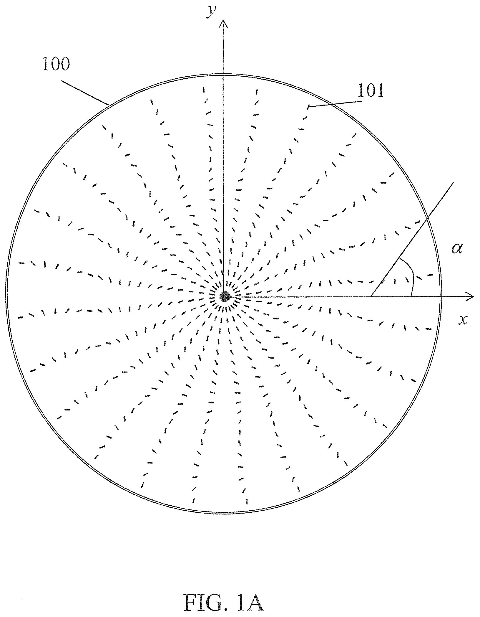
In the present invention, such components are obtained on the basis of diffractive waveplates. An exemplary structure of one of the optical components of interest is schematically shown in FIG. 1. Essentially, it is an optically anisotropic film 100 with the optical axis orientation 101 rotating in the plane of the film, the x,y plane in FIG. 1. The thickness L of the film is defined by half-wave phase retardation condition L=.lamda./n.sub..parallel.-n.sub..perp.), where n.sub..parallel. and n.sub..perp. are the principal values of the refractive indices of the material; and .lamda. is the radiation wavelength. The required half-wave phase retardation condition can be met for as low as a few micrometer thick films, particularly, for liquid crystalline materials. Such a structure imposes a phase shift .PHI.=.+-.2 .alpha.(x,y) on circular polarized beams propagating through it with the sign depending on the handedness of polarization. In simplest realization, the rotation angle .alpha. of the optical axis orientation is a linear function of a single coordinate, .alpha.=2.pi.x/.LAMBDA. with .LAMBDA. characterizing the period of the pattern. With account of .alpha.=2.pi.x/.LAMBDA.=qx, where q=2.pi.x/.LAMBDA., an unpolarized beam is thus diffracted by the diffractive waveplate into +/-1st diffraction orders with the magnitude of the diffraction angle equal to .lamda./.LAMBDA.. The phase .PHI. in the equation above, known as geometrical or Pancharatnam phase, does not depend on wavelength, hence the broadband nature of the diffraction. Due to its half-wave plate nature, there are well developed techniques for making the component essentially achromatic in a wide range of wavelengths. In case of quadratic variation pattern of the optical axis orientation, .alpha..about.x.sup.2 or, in two dimensional case, .alpha..about.x.sup.2+y.sup.2, the parabolic phase modulation profile produces cylindrical or spherical lens action, correspondingly.
Thus, there is a need and an opportunity provided by the current invention for fabricating lenses and other nonlinear phase modulating components that could be obtained in the form of thin film structurally continuous coatings on a variety of substrates.
BRIEF SUMMARY OF THE INVENTION
The objective of the present invention is providing structurally continuous thin film lenses, positive or negative.
The second objective of the present invention is providing a polarizing lens.
The third objective of the present invention is providing a lens with polarization dependent power sign.
The fourth objective of the present invention is providing a lens wherein the power can be varied (increased) without varying (increasing) thickness.
The fifth objective of the present invention is providing means for fabricating aspherical optical components in the form of thin film coatings.
The sixth objective of the present invention is providing thin film variable lens.
The seventh objective of the present invention is providing micro lenses and their arrays as thin film coatings.
The eight objective of the present invention is providing broadband/achromatic thin film lenses for different spectral range.
The ninth objective of the present invention is providing a method for fabricating and replicating waveplate lenses.
Still another objective of the present invention is providing electrically controlled waveplate lenses.
BRIEF DESCRIPTION OF THE SEVERAL VIEWS OF THE DRAWINGS
FIG. 1A shows spatial distribution of optical axis orientation in a vortex waveplate lens.
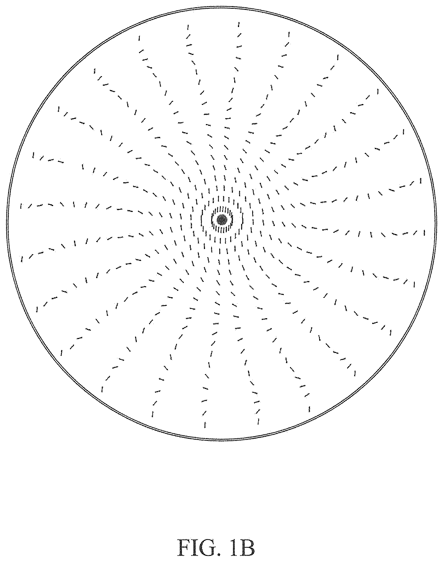
FIG. 1B shows spatial distribution of optical axis orientation in a spherical waveplate lens.
FIG. 1C shows spatial distribution of optical axis orientation in a cylindrical waveplate lens.
FIG. 2 schematically shows a shape-variant polarization converter comprising a concave and a convex lens sandwiching a planar aligned nematic liquid crystal in-between. A cylindrical system is shown for drawing simplicity.
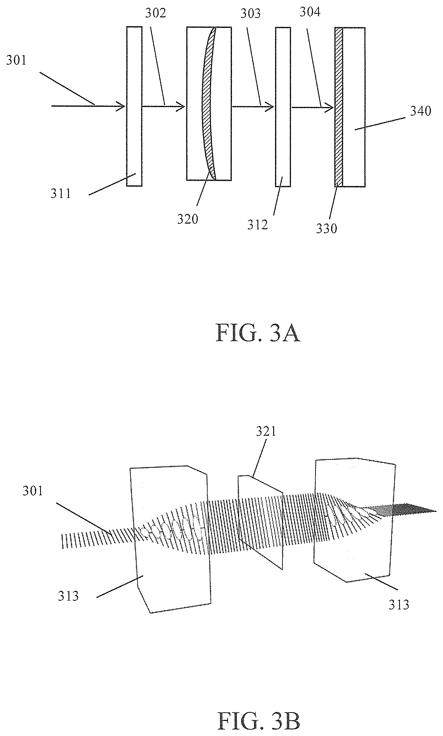
FIG. 3A schematically shows an optical system for recording nonlinear variation patterns for liquid crystal orientation on a substrate coated with a photoaligning material film.
FIG. 3B schematically shows an optical system with a biriefringent wedge acting as spatial light polarization modulator, and twist oriented liquid crystal cells as polarization converter components.
FIG. 4 shows photos of a laser beam received at the output of the optical recording system observed with and without a polarizer for both a cylindrical and a spherical birefringent lens.
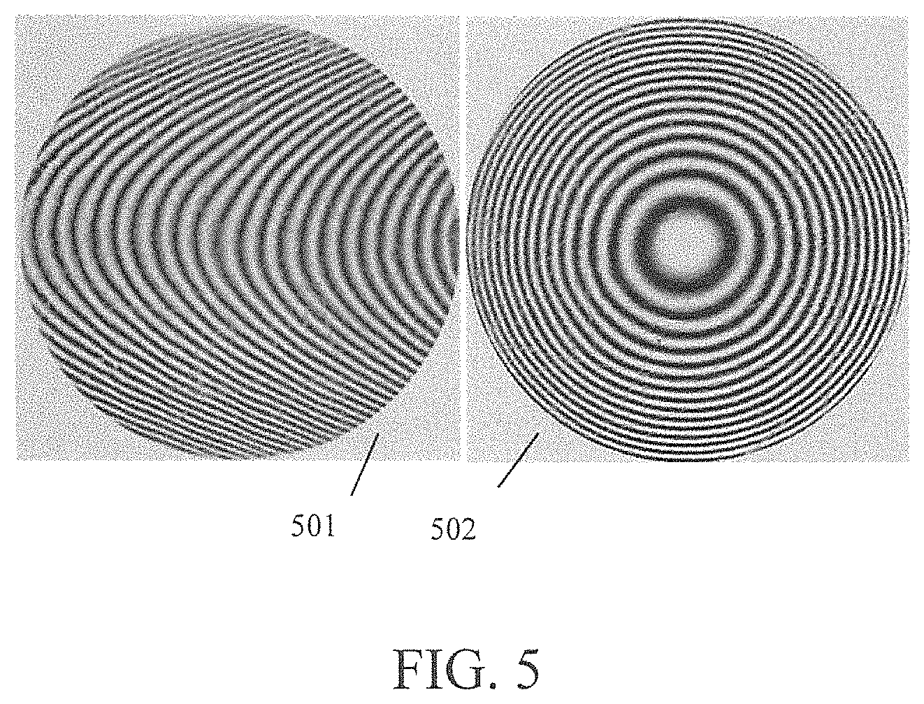
FIG. 5 shows photos of liquid crystal polymer films photoaligned with a cylindrical and spherical lens. Photos are obtained between crossed polarizers.
FIG. 6A shows photos of a laser beam focused with a cylindrical waveplate-lens for different polarization states: linear, right-hand circular, and left-hand circular.
FIG. 6B shows far field photos of a laser beam focused with a cylindrical waveplate-lens for different polarization states: linear, right-hand circular, and left-hand circular.
FIG. 6C shows photos of projections of a triangular aperture with a spherical waveplate-lens for different polarization states: linear, right-hand circular, and left-hand circular. Photos are obtained at planes before, at, and far from the focus of the lens.
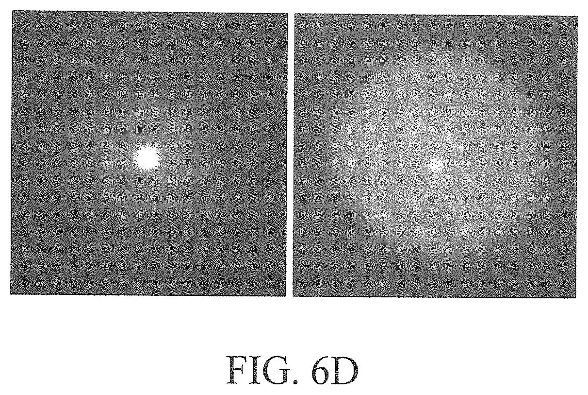
FIG. 6D shows switching the focusing state to defocusing state by switching the handedness of a circular polarized beam.
FIG. 7 shows photos of a cylindrical and spherical waveplate-microlenses.
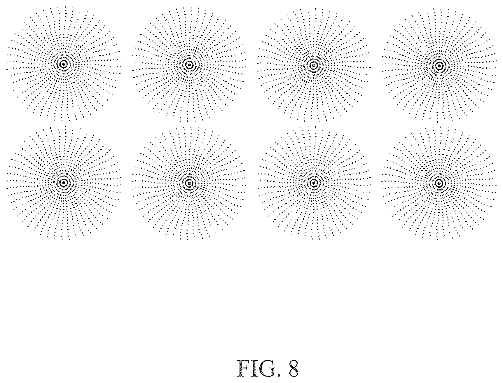
FIG. 8 schematically shows an array of spherical microlenses.
DETAILED DESCRIPTION OF THE INVENTION
Before explaining the disclosed embodiment of the present invention in detail it is to be understood that the invention is not limited in its application to the details of the particular arrangement shown since the invention is capable of other embodiments. Also, the terminology used herein is for the purpose of description and not limitation.
Patterns of optical axis orientation demonstrating examples of waveplate lenses of current invention are shown in FIG. 1. An example of a key component of spatially nonlinear polarization converting system of the present invention shown in FIG. 2 comprises a cylindrical plano-convex lens 202 and a cylindrical plano-concave lens 201 sandwiching a planar aligned nematic liquid crystal (NLC) layer 203. Cylindrical or spherical lenses are used for fabricating cylindrical or spherical waveplate lenses, correspondingly. The focal length of plano-convex and plano-concave lenses can be chosen to create a cell gap between the lenses with depth as small as 1 .mu.m or as large as 1 mm. For example, a lense of focal length F1=150 mm with curvature radii ?? can be combined with a lens of focal length F2=-100 mm with curvature radii ?? for obtaining a gap of 340 .mu.m.
To align the NLC layer within the lenses, the surfaces of the lenses that are in touch with the NLC can be spin-coated with 0.5 wt. % solution of PVA in distilled water at 3000 rpm for 30 s. Then, they can be dried during 20 min at 100.degree. C. and rubbed with a soft cloth in one direction. NLC E48 (Merck) can be used to fill in the cells, as an example.
This shape-variant birefringent film 203 provides spatially varying phase retardation acting as a spatial light polarization modulator (SLPM). The polarization control system may further incorporate additional polarizing optics that ensures equality of the electric field strength of ordinary and extraordinary wave components generated in the SLPM film. For example, when using a linear polarized laser beam 301 in FIG. 3A, a quarter-waveplate 311 can be used for creating a circular polarized light beam incident on the SLPM film 320 as shown in FIG. 3A. Alternatively, a twisted liquid crystal polarization rotator 313 can be used to rotate the polarization of the incident light beam 301 to arrange it at 45 degrees with respect to the anisotropy axis of the SLPM film 320 as show in FIG. 3B. The spatial modulation of polarization obtained at the output of the film is further transformed by a second quarter-waveplate 312 in the schematic shown in FIG. 3A or a twisted nematic film 313 in the example shown in FIG. 3B. Thus, cyclodal distribution of light polarization can be obtained in a particular case of a SLPM film in the form of a birefringent wedge 321 in FIG. 3B. The twist angle, when using NLC cells for controlling the beam polarization at the input and output of the SLPM film may be 45 degrees as depicted schematically in FIG. 3B. The mutual alignment of the axes of the quarter-waveplates in FIG. 3A or the twist NLC cells in FIG. 3B shall be such as the transmitted beam is linear polarized at the absence of the SLPM film.
An expanded beam of an Argon ion laser operating at 488 nm wavelength providing a power density 12 mW/cm.sup.2 can be used for photoalignment of the photoaligning layer 330 deposited on a support substrate 340. The beam propagates through two quarter waveplates and the SLPM film 320 between them in FIG. 3A. In the example shown in FIG. 3B, the beam propagates through the system of two polarization rotators and the SLPM film 321 between them.
The pattern of polarization distribution of the beam at the output of the system can be verified with a linear polarizer on a screen. Cylindrical and spherical cycloidal distribution of polarization is shown in FIG. 4. The item 401 in FIG. 4 corresponds to the pattern observed without polarizers. It shows homogeneous distribution of light intensity since the only parameter being modulated is polarization. In contrast, polarization modulation is revealed between polarizers as parabolic fringes in case of cylindrical lens 402 and concentric modulation pattern in case of a spherical lens 403.
The polarization modulation patterns can be recorded, as an example, on PAAD series photoalignment material layers (available at beamco.com). The PAAD layer is created on a substrate, glass, for example, by spin-coating a solution of PAAD-72(1%)/DMF at 3000 rpm during 30 s. PAAD layer can be pre-exposed with linear polarized LED light, 459 nm wavelength, for example, before recording the lens; the pre-exposure time is approximately 10 min at power density 10 mW/cm.sup.2. The pre-aligned PAAD layer is exposed then to the Argon ion laser beam during 60 s.
Having thus created the required alignment conditions, the PAAD coated substrate can be coated with layers of liquid crystal monomer solution, for example, RMS-03-001C (Merck, Ltd.), followed by photopolymerization with unpolarized UV light at 365 nm wavelength during 5 min. The first layer of the RMS-03-001C can be spin-coated on PAAD-72 layer at a speed 3000 rpm during 1 min. A second layer of RMS-03-001C can be spin-coated on the first layer at a 2000 rpm during 1 min followed by photopolymerization as indicated above to create half-wave phase retardation condition at, for example, 633 nm wavelength.
Alternatively, photoaligned substrates can be used for making electrically or optically controlled liquid crystal cells resulting in electrically or optically controlled waveplate lenses.
Cylindrical and spherical LC polymer lens structures are shown in FIG. 5, items 501 and 502, correspondingly, between crossed polarizers. Focusing and defocusing patterns of a red laser beam on above structures are shown in FIG. 6 at different conditions. The Focal length of the cylindrical waveplate-lenses used in FIG. 6 is 84 cm and 7 cm: photos 601-603 (F=84 cm) are obtained in its focal plane. Photos 607-609 (F=7 cm) correspond to far field zone. Photos 601, and 607 correspond to linear polarized incident light. Photos 602, and 608 correspond to left-hand circular polarized incident beam. The photos 603, and 609 correspond to right-hand circular polarized incident beam.
Projection of a mask with a triangular opening with the aid of a spherical cycloidal lens is shown in FIG. 6. Photos 611, 612, and 613 were taken behind the lens before focus. Photos 621, 622, and 623 were taken at the focus of the lens (F=190 mm), and the Photos 631, 632, and 633 were taken far from the focus. The photos 611, 621 and 631 correspond to linear polarized or unpolarized incident beam. The photos 612, 622 and 632 correspond to left-hand circular polarized incident beam, and the photos 613, 623, and 633 correspond to right-hand circular polarized beam, correspondingly. The focusing conditions can be controlled by using electrically or optically controlled phase retardation plates to modulate the polarization state and distribution in the input light.
Lenses of different focal length can be recorded by simply changing the size of the polarization modulation pattern projected onto the photoalignment layer. FIG. 7 shows examples of lenses of less than a mm diameter. The projection can be simply made by a focusing lens placed after the output quarter-wave plate. Lens size of 0.6 mm, for example, corresponded to a focal length of 3 mm while a lens size of 6 mm exhibited a focal length of 475 mm. Arrays of such microlenses can be printed as schematically shown in FIG. 8.
Although the present invention has been described above by way of a preferred embodiment, this embodiment can be modified at will, within the scope of the appended claims, without departing from the spirit and nature of the subject invention.
* * * * *
D00000
D00001
D00002
D00003
D00004
D00005
D00006
D00007
D00008
D00009
D00010
D00011
D00012
XML
uspto.report is an independent third-party trademark research tool that is not affiliated, endorsed, or sponsored by the United States Patent and Trademark Office (USPTO) or any other governmental organization. The information provided by uspto.report is based on publicly available data at the time of writing and is intended for informational purposes only.
While we strive to provide accurate and up-to-date information, we do not guarantee the accuracy, completeness, reliability, or suitability of the information displayed on this site. The use of this site is at your own risk. Any reliance you place on such information is therefore strictly at your own risk.
All official trademark data, including owner information, should be verified by visiting the official USPTO website at www.uspto.gov. This site is not intended to replace professional legal advice and should not be used as a substitute for consulting with a legal professional who is knowledgeable about trademark law.