Motorized window covering having powered modules
Whitmire , et al. October 13, 2
U.S. patent number 10,801,260 [Application Number 15/956,576] was granted by the patent office on 2020-10-13 for motorized window covering having powered modules. This patent grant is currently assigned to TTI (MACAO COMMERCIAL OFFSHORE) LIMITED. The grantee listed for this patent is TTI (MACAO COMMERCIAL OFFSHORE) LIMITED. Invention is credited to Mark Huggins, J. Luke Jenkins, Tanvi Singh, J. Porter Whitmire.

| United States Patent | 10,801,260 |
| Whitmire , et al. | October 13, 2020 |
Motorized window covering having powered modules
Abstract
A window covering assembly includes one or more powered modules, such as a light, temperature sensor, fan, heater, or motion detector. The window covering assembly is configured so that the modules may be attached to the window covering assembly in numerous configurations, thus permitting tailored features of the window covering assembly.
| Inventors: | Whitmire; J. Porter (Greenville, SC), Huggins; Mark (Anderson, SC), Singh; Tanvi (Pune, IN), Jenkins; J. Luke (Anderson, SC) | ||||||||||
|---|---|---|---|---|---|---|---|---|---|---|---|
| Applicant: |
|
||||||||||
| Assignee: | TTI (MACAO COMMERCIAL OFFSHORE)
LIMITED (Macau, MO) |
||||||||||
| Family ID: | 1000005111996 | ||||||||||
| Appl. No.: | 15/956,576 | ||||||||||
| Filed: | April 18, 2018 |
Prior Publication Data
| Document Identifier | Publication Date | |
|---|---|---|
| US 20180305979 A1 | Oct 25, 2018 | |
Related U.S. Patent Documents
| Application Number | Filing Date | Patent Number | Issue Date | ||
|---|---|---|---|---|---|
| 62487376 | Apr 19, 2017 | ||||
| Current U.S. Class: | 1/1 |
| Current CPC Class: | E06B 9/322 (20130101); E06B 9/42 (20130101); E06B 9/50 (20130101); E06B 9/70 (20130101); E06B 2009/2627 (20130101) |
| Current International Class: | E06B 9/70 (20060101); E06B 9/42 (20060101); E06B 9/50 (20060101); E06B 9/322 (20060101); E06B 9/262 (20060101) |
References Cited [Referenced By]
U.S. Patent Documents
| 5148849 | September 1992 | Faludy |
| 6674255 | January 2004 | Schnebly |
| 6850017 | February 2005 | Domel |
| 6983783 | January 2006 | Carmen, Jr. |
| 7281561 | October 2007 | Anderson |
| 7338050 | March 2008 | Tellez |
| 7931068 | April 2011 | Carmen, Jr. |
| 8307878 | November 2012 | Faller |
| 8417388 | April 2013 | Altonen |
| 8571719 | October 2013 | Altonen |
| 8659246 | February 2014 | Mullet |
| 8666555 | March 2014 | Altonen |
| 8723454 | May 2014 | Skinner |
| 8866343 | October 2014 | Abraham |
| 8901769 | December 2014 | Altonen |
| 8946924 | February 2015 | Pessina |
| 8947027 | February 2015 | Mullet |
| 8975778 | March 2015 | Altonen |
| 9013059 | April 2015 | Altonen |
| 9124130 | September 2015 | Altonen |
| 9152032 | October 2015 | Mullet |
| 9169690 | October 2015 | Blair |
| 9249623 | February 2016 | Mullet |
| 9267327 | February 2016 | Feldstein |
| 9366082 | June 2016 | Feldstein |
| 9410371 | August 2016 | Faller |
| 9670725 | June 2017 | Gill |
| 9745797 | August 2017 | Mullet |
| 9970669 | May 2018 | Chang |
| 9991710 | June 2018 | Altonen |
| 10113360 | October 2018 | Hall |
| 10119330 | November 2018 | Brunk |
| 10358869 | July 2019 | Feldstein |
| 10514963 | December 2019 | Shrivastava |
| 10520784 | December 2019 | Brown |
| 2005/0022946 | February 2005 | Domel |
| 2007/0187042 | August 2007 | Kallstrom |
| 2007/0284053 | December 2007 | Mullet |
| 2008/0053628 | March 2008 | Anderson |
| 2008/0236763 | October 2008 | Kates |
| 2009/0308543 | December 2009 | Kates |
| 2011/0283632 | November 2011 | Sutton |
| 2012/0285666 | November 2012 | Klimaszewski |
| 2014/0045419 | February 2014 | Bartmann |
| 2014/0090787 | April 2014 | Colson |
| 2015/0191959 | July 2015 | Schmohl |
| 2015/0234369 | August 2015 | Wen |
| 2016/0054023 | February 2016 | Baker |
| 2018/0223596 | August 2018 | Hall |
| 2018/0305978 | October 2018 | Whitmire |
| 2018/0305979 | October 2018 | Whitmire |
| 2018/0347272 | December 2018 | Gill |
| 2019/0024452 | January 2019 | Derk, Jr. |
| 2019/0128053 | May 2019 | Patel |
| 2019/0145166 | May 2019 | Campagna |
| 2019/0218859 | July 2019 | Campagna |
| 2019/0226275 | July 2019 | Miller |
| 2019/0271155 | September 2019 | Gilbertson |
| 2019/0384652 | December 2019 | Shrivastava |
| 3002228 | Oct 2018 | CA | |||
| 2004012818 | Jan 2004 | JP | |||
Other References
|
Shimada Junzo, English translation of "JP2004012818A", obtained from <https://worldwide.espacenet.com/?locale=en_EP>. (Year: 2004). cited by examiner. |
Primary Examiner: Shablack; Johnnie A.
Attorney, Agent or Firm: Morgan, Lewis & Bockius, LLP
Parent Case Text
This application claims the benefit of U.S. Provisional Application No. 62/487,376, filed Apr. 19, 2017, the contents of which are hereby incorporated by reference in their entirety.
Claims
What is claimed is:
1. A window covering assembly comprising: a roller; a motor assembly disposed proximate to the roller; a window cover attached to the roller; a receptacle installed on the window covering assembly; a first powered module configured for placement in the receptacle, the first powered module configured to cause performance of a first task; and a second powered module configured for placement in the receptacle, the second powered module configured to cause performance of a second task that is different than the first task, wherein: the window cover is raised when the roller rotates in a first angular direction, the window cover is lowered when the roller rotates in a second angular direction, opposite the first angular direction, the motor assembly interfaces with the roller via a power transmission system, the motor assembly is powered by a battery cell integral to the window covering assembly for actuating the power transmission system, the first powered module and the second powered module have a same outer profile for interchangeable installation within the receptacle, the first powered module and the second powered module are powered by the battery cell, the first powered module includes a light for performing the first task, and the second powered module includes a temperature sensor, a fan, a heater, or a motion sensor for performing the second task.
2. The window covering assembly according to claim 1, wherein the first powered module includes the light and the second powered module includes the heater.
3. The window covering assembly according to claim 1, further comprising a plurality of receptacles configured to receive the first powered module and the second powered module.
4. The window covering assembly according to claim 1, wherein the first powered module includes the light and the second powered module includes the temperature sensor.
5. The window covering assembly according to claim 1, wherein the first powered module includes the light and the second powered module includes the motion sensor.
6. A window covering assembly comprising: a roller; a motor assembly disposed proximate to the roller; a window cover attached to the roller; a receptacle installed on the window covering assembly; a first powered module configured for placement in the receptacle, the first powered module configured to cause performance of a first task; and a second powered module configured for placement in the receptacle, the second powered module configured to cause performance of a second task that is different than the first task, wherein: the window cover is raised when the roller rotates in a first angular direction, the window cover is lowered when the roller rotates in a second angular direction, opposite the first angular direction, the motor assembly interfaces with the roller via a power transmission system, the motor assembly is powered by a battery cell integral to the window covering assembly for actuating the power transmission system, the first powered module and the second powered module have a same outer profile for interchangeable installation within the receptacle, the first powered module and the second powered module are powered by the battery cell.
7. The window covering assembly according to claim 6, wherein: the first powered module includes one of a light, a fan, and a heater, the second powered module includes one of a temperature sensor and a motion sensor, and the first powered module is activated based on a condition sensed by the second powered module.
Description
SUMMARY OF THE INVENTION
The present invention relates to a window covering assembly, and more particularly, to such an assembly that includes one or more powered modules. These modules may be a light, temperature sensor, fan, heater, or motion detector. A user is able to select the appropriate type and quantities of modules for a given window covering assembly.
BRIEF DESCRIPTION OF THE DRAWING
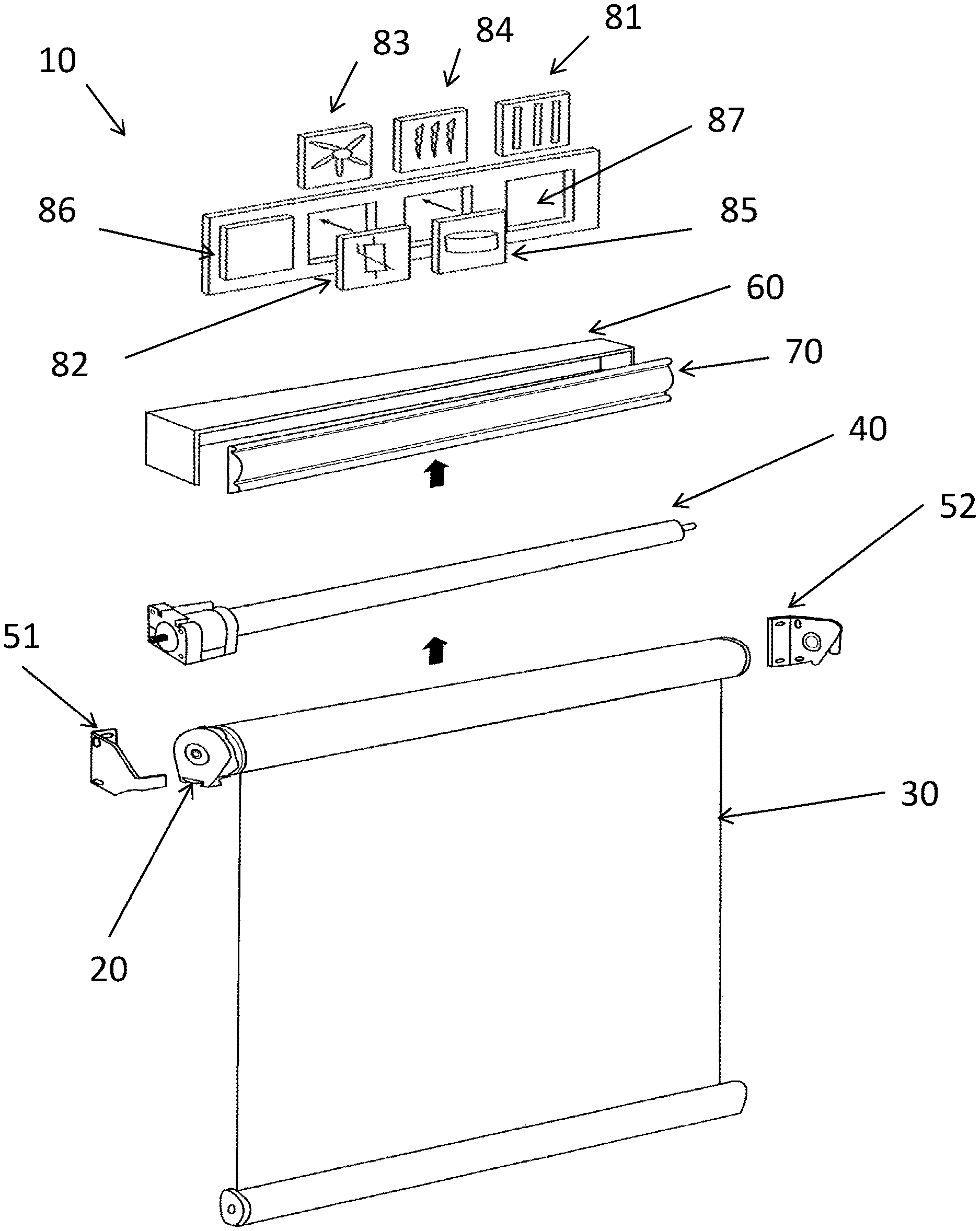
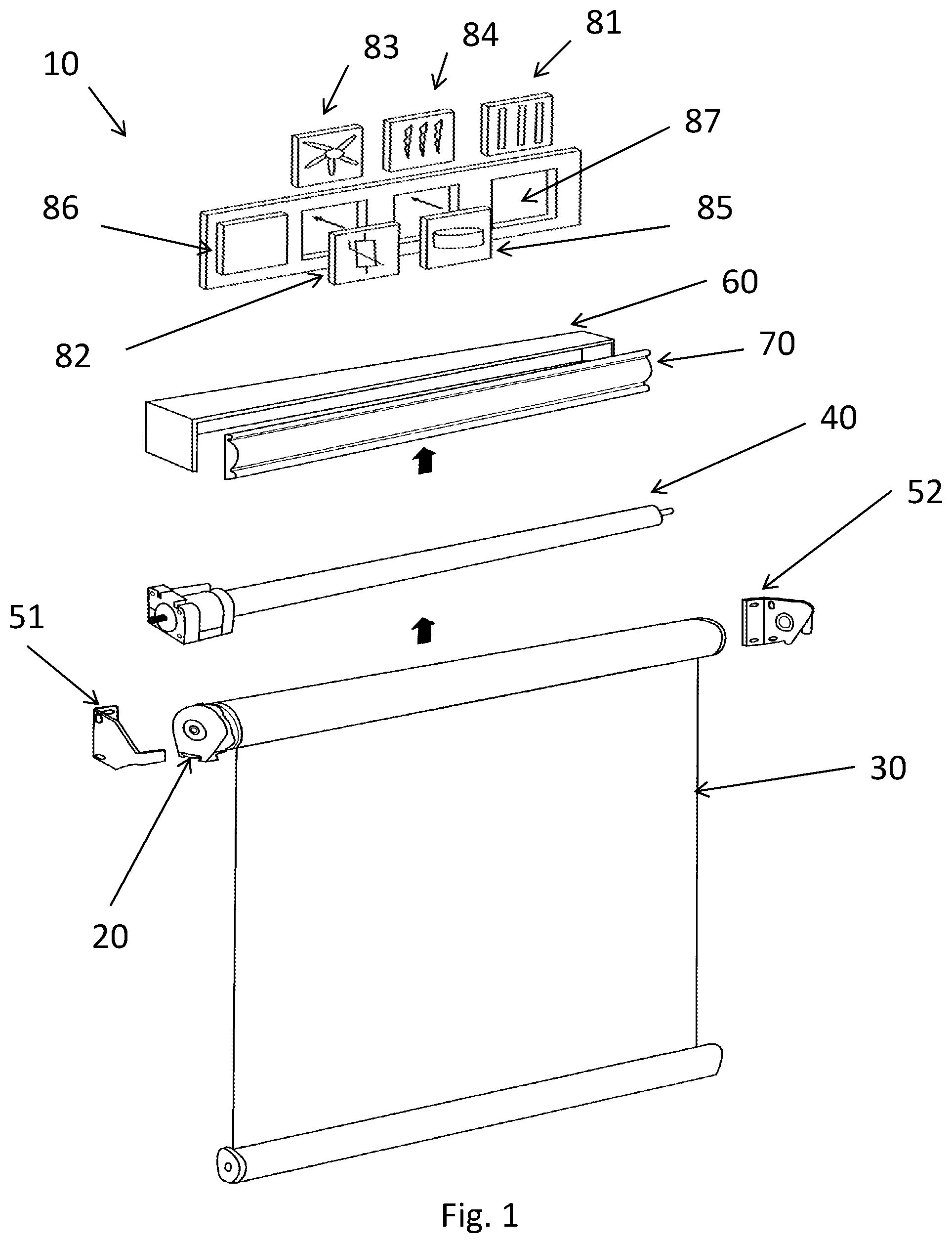
FIG. 1 is an exploded view of a window covering assembly according to one exemplary embodiment of the present invention.
FIG. 2 is a side view of a window covering assembly according to one exemplary embodiment of the present invention.
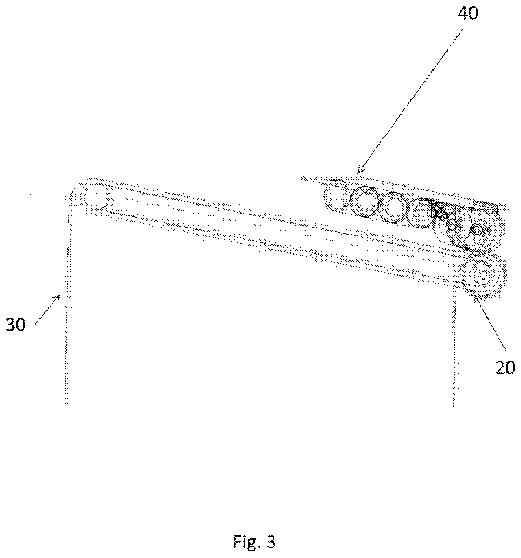
FIG. 3 is a perspective view of a window covering assembly according to one exemplary embodiment of the present invention.
DETAILED DESCRIPTION OF THE PREFERRED EMBODIMENT
Reference will now be made in detail to the preferred embodiment of the present invention, which is illustrated in the accompanying drawing.
FIGS. 1-3 show a window covering assembly according to one embodiment of the present invention. As shown in FIG. 1, the window covering assembly 10 may include a roller 20, around which a window cover 30 is wound. Upon rotation of the roller 20, window cover 30 is either raised or lowered, depending on the direction of rotation of roller 20. In one embodiment, window cover 30 is a screen; however, other window coverings may be used. For example, cellular blinds, as are commonly known in the art, may be used. In case of cellular blinds, the blinds are not wound around roller 20. Rather, a string that is attached to the bottom of the blinds is wound around a spool. Upon rotation of the spool, the bottom of the string is either raised or lowered, depending on the direction of rotation of the spool. This, in turn, either raises or lowers the cellular blinds.
As is also shown in FIG. 1, the window covering assembly 10 may include a motor assembly 40. In one embodiment, this assembly includes a motor which, when activated, causes a shaft to rotate. As shown in FIGS. 2 and 3, this shaft may be connected to a spur gear that interfaces with a matching spur gear on the roller 20. In this way, the roller is caused to rotate and thereby raise or lower the window cover 30. The present invention is not limited to the power transmission system just described. Other gearing mechanisms may be used, and other power transmission systems, including chain drives and belt drives, may be used.
As is also shown in FIG. 1, the window covering assembly 10 may include mounting brackets 51, 52. In one embodiment, these mounting brackets secure the roller 20 and motor assembly 40 to a window frame. A roller channel 60 and valance 70 may be placed over the roller 20 and motor assembly 40 when the window covering assembly 10 is installed in a window frame. This visually obscures the roller 20 and motor assembly 40, increasing the aesthetic appearance of the window covering assembly 10.
In one embodiment of the present invention, one or more powered modules may be attached to the window covering assembly 10. Exemplary powered modules include a light 81, temperature sensor 82, fan 83, heater 84, and motion detector 85. The window covering assembly 10 is configured to receive any configuration of these modules. This allows for a window covering assembly 10 with tailored features. For example, a window covering assembly 10 may include a motion detector and a light. Controls may be provided such that when a person walks in the vicinity of the window covering assembly, the light is turned on. As another example, a window covering assembly 10 may include a temperature sensor and a heater. Controls may be provided such that when the temperature sensor detects that the ambient temperature is below a certain threshold temperature, the heater is activated. It will be apparent to one of skill in the art that the preceding are only exemplary, and any combination of the powered modules may be employed in a window covering assembly 10.
In one embodiment, the modules are powered by a battery cell 86 that is integral to the window covering assembly 10. This battery cell may also be the source of power for the motor assembly 40.
In one embodiment, all of the modules that may be installed on a window covering assembly 10 have the same outer profile, and the window covering assembly has receptacles 87 configured to receive the modules. In this way, any module may be placed in any of the receptacles of the window covering assembly 10.
It will be apparent to those skilled in the art that various modifications and variations can be made in the modular motorized window blinds assembly of the present invention without departing from the spirit or scope of the invention. Thus, it is intended that the present invention cover modifications and variations of this invention provided they come within the scope of the appended claims and their equivalents.
* * * * *
References
D00000
D00001
D00002
D00003
XML
uspto.report is an independent third-party trademark research tool that is not affiliated, endorsed, or sponsored by the United States Patent and Trademark Office (USPTO) or any other governmental organization. The information provided by uspto.report is based on publicly available data at the time of writing and is intended for informational purposes only.
While we strive to provide accurate and up-to-date information, we do not guarantee the accuracy, completeness, reliability, or suitability of the information displayed on this site. The use of this site is at your own risk. Any reliance you place on such information is therefore strictly at your own risk.
All official trademark data, including owner information, should be verified by visiting the official USPTO website at www.uspto.gov. This site is not intended to replace professional legal advice and should not be used as a substitute for consulting with a legal professional who is knowledgeable about trademark law.