Soft top convertible wind deflector
Lovasz , et al. October 13, 2
U.S. patent number 10,800,236 [Application Number 16/276,945] was granted by the patent office on 2020-10-13 for soft top convertible wind deflector. This patent grant is currently assigned to FORD GLOBAL TECHNOLOGIES, LLC. The grantee listed for this patent is FORD GLOBAL TECHNOLOGIES, LLC. Invention is credited to Spencer M. Hicks, Ronald M. Lovasz.


| United States Patent | 10,800,236 |
| Lovasz , et al. | October 13, 2020 |
Soft top convertible wind deflector
Abstract
A vehicle includes a header extending laterally between A-pillars, and a soft top, including a movable frame defining a roof of the vehicle and having a header bow that is selectively securable to the header, the frame movable between a forward closed position and a rearward retracted position. A wind deflector is mounted to the frame adjacent to the header bow and movable with the frame between the closed position and the retracted position, with the wind deflector positioned in front of the header bow when not in the closed position.
| Inventors: | Lovasz; Ronald M. (Allen Park, MI), Hicks; Spencer M. (Pinckney, MI) | ||||||||||
|---|---|---|---|---|---|---|---|---|---|---|---|
| Applicant: |
|
||||||||||
| Assignee: | FORD GLOBAL TECHNOLOGIES, LLC
(Dearborn, MI) |
||||||||||
| Family ID: | 1000005111108 | ||||||||||
| Appl. No.: | 16/276,945 | ||||||||||
| Filed: | February 15, 2019 |
Prior Publication Data
| Document Identifier | Publication Date | |
|---|---|---|
| US 20200262281 A1 | Aug 20, 2020 | |
| Current U.S. Class: | 1/1 |
| Current CPC Class: | B60J 7/223 (20130101); B60J 7/1291 (20130101) |
| Current International Class: | B60J 7/22 (20060101); B60J 7/12 (20060101) |
| Field of Search: | ;296/109,116,107.09 |
References Cited [Referenced By]
U.S. Patent Documents
| 2827328 | March 1958 | O'Kane |
| 4538852 | September 1985 | Lobo |
| 5833305 | November 1998 | Watzlawick et al. |
| 6416120 | July 2002 | Schutt |
| 6443520 | September 2002 | Schmaelzle et al. |
| 9073420 | July 2015 | Bauer |
| 9908392 | March 2018 | Nania |
| 10059386 | August 2018 | Caples |
| 2005/0110306 | May 2005 | Queveau |
| 2017/0305244 | October 2017 | Kamioka |
| 2018/0001753 | January 2018 | Kroeber |
| 2018/0272848 | September 2018 | Biasi Da Silva et al. |
| 19535593 | Mar 1997 | DE | |||
| 19646240 | May 1998 | DE | |||
| 102013102643 | Sep 2014 | DE | |||
Other References
|
Machine Translation of DE19646240A1, printed from the EPO website, May 26, 2020. cited by examiner. |
Primary Examiner: Morrow; Jason S
Attorney, Agent or Firm: Coppiellie; David MacMillan, Sobanski & Todd, LLC
Claims
The invention claimed is:
1. A vehicle comprising: a header extending laterally between A-pillars; a soft top, including a movable frame defining a roof of the vehicle and having a header bow that is selectively securable to the header, the frame movable between a forward closed position and a rearward retracted position; and a wind deflector mounted to the frame adjacent to the header bow and movable with the frame between the closed position and the retracted position, with the wind deflector positioned in front of the header bow when not in the closed position, wherein the wind deflector includes a deflector beam configured to direct air up over the header bow when the soft top is not in the closed position, and wherein the deflector includes a pair of longitudinally extending arms that support the deflector beam on the header bow.
2. The vehicle of claim 1 wherein the arms are configured to pivot the deflector beam under the header bow when the soft top is in the closed position and pivot the deflector beam in front of the header bow when the soft top is not in the closed position.
3. The vehicle of claim 1 wherein the header bow is configured to be exposed to an air stream flowing past the vehicle when in the retracted position.
4. A method of operating a soft top of a vehicle comprising: releasing a header bow of a soft top from a header of the vehicle; pivoting a wind deflector from under the header bow to in front of the header bow as the header bow moves out of contact with the header; and redirecting air flow, with the wind deflector, up and over the header bow as the vehicle moves forward.
5. The method of claim 4 further comprising: moving the wind deflector rearward with the header bow as the soft top moves rearward from the closed position to the retracted position.
6. The method of claim 5 wherein the wind deflector includes a laterally extending deflector beam and arms extending from the deflector beam that mount the deflector beam to the header bow; and the arms pivoting the deflector beam from a position under the header bow when the soft top is in the closed position to in front of the header bow when the soft top is not in a closed position.
7. The method of claim 4 wherein the wind deflector includes a laterally extending deflector beam and arms extending from the deflector beam that mount the deflector beam to the header bow; and the arms pivoting the deflector beam from a position under the header bow when the soft top is in the closed position to in front of the header bow when the soft top is not in a closed position.
8. A vehicle comprising: a header extending laterally between A-pillars; a soft top, including a movable frame defining a roof of the vehicle and having a header bow that is selectively securable to the header, the frame movable between a forward closed position and a rearward retracted position; and a wind deflector mounted to the frame adjacent to the header bow and movable with the frame between the closed position and the retracted position, with the wind deflector positioned in front of the header bow when not in the closed position, wherein the wind deflector is configured to pivot the deflector beam under the header bow when the soft top is in the closed position and pivot the deflector beam in front of the header bow when the soft top is not in the closed position.
Description
BACKGROUND OF THE INVENTION
The present invention relates to a vehicle having a soft top convertible roof and more particularly to a wind deflector for such a vehicle roof.
For many conventional vehicles having convertible roofs the soft top or convertible top are designed to stow inside the vehicle structure when retracted, which protects the soft material while in such retracted position. However, for some vehicles, it may be preferred to have the soft top/convertible sit above the vehicle structure when the in fully retracted position, which allows the air flow from vehicle movement to enter the front (leading) edge of the top. This air flow when in such an exposed retracted position may allow for buffeting or ballooning of the soft top to occur.
SUMMARY OF THE INVENTION
An embodiment contemplates a vehicle including a header extending laterally between A-pillars; a soft top, including a movable frame defining a roof of the vehicle and having a header bow that is selectively securable to the header, the frame movable between a forward closed position and a rearward retracted position; and a wind deflector mounted to the frame adjacent to the header bow and movable with the frame between the closed position and the retracted position, with the wind deflector positioned in front of the header bow when not in the closed position.
An embodiment contemplates a method of operating a soft top of a vehicle may comprise releasing a header bow of a soft top from a header of the vehicle; pivoting a wind deflector from under the header bow to in front of the header bow as the header bow moves out of contact with the header; and redirecting air flow, with the wind deflector, up and over the header bow as the vehicle moves forward.
An advantage of an embodiment is a wind deflector that is located at the front of the soft top/soft convertible top header bow avoids potentially undesirable buffeting or ballooning of the top when in the fully retracted position. In addition, the wind deflector articulates automatically as the soft top/convertible top system moves from the closed position to the top fully retracted position.
BRIEF DESCRIPTION OF THE DRAWINGS
FIG. 1 is a schematic side view of a portion of a vehicle having a soft top shown in a mostly closed position.
FIG. 2 is a schematic perspective view of a wind deflector.
FIG. 3 is a schematic view similar to FIG. 1, showing the wind deflector in a different position.
FIG. 4 is a schematic view similar to FIG. 1, showing the soft top in a partially open (partially retracted) position.
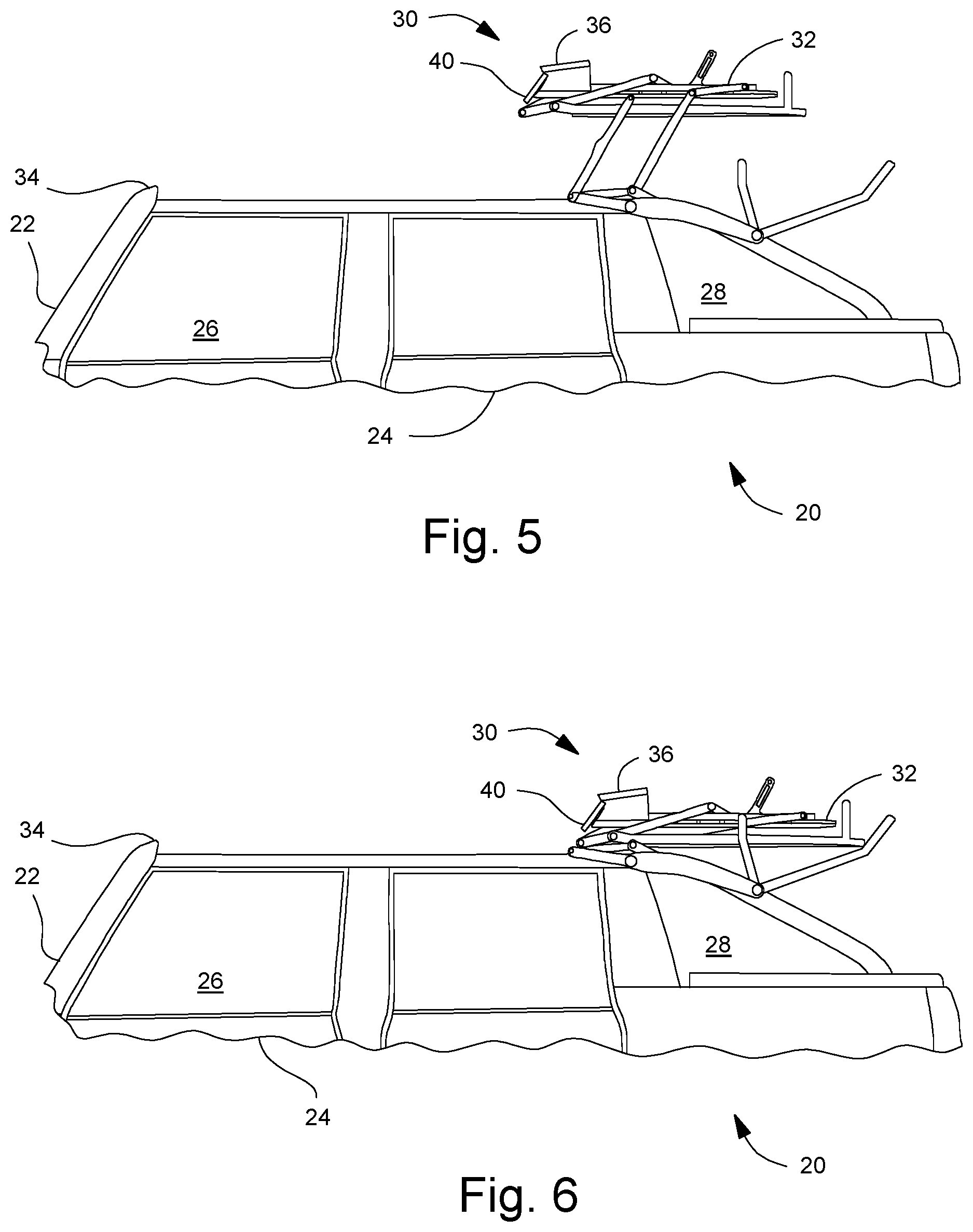
FIG. 5 is a schematic view similar to FIG. 1, showing the soft top in a mostly open (mostly retracted) position.
FIG. 6 is a schematic view similar to FIG. 1, showing the soft top in a fully open (retracted) position.
DETAILED DESCRIPTION
FIGS. 1-6 illustrate a vehicle 20 having A-pillars 22 extending vertically along the sides of a windshield, side doors 24, providing access to a passenger compartment 26, and a rear cargo area 28.
The vehicle 20 has a soft top 30, which is a frame 32 covered by a soft material, such as cloth, that essentially forms the roof of the vehicle 20. The soft top 30 is movable between a closed position, where it extends over and seals the top of the passenger compartment 26, and a retracted position where the roof is open to outside of the vehicle 20. The figures herein show a soft top where the middle portion of the roof is covered with the frame 32 and soft material between rigid portions of the vehicle body, but the soft top may also include vehicles where the entire roof is formed from the frame 32 and soft material as well.
Extending laterally (i.e., side-to-side) between the top of each A-pillar 22, along the top of the windshield, is a header 34. The frame 32 includes header bow 36 that is selectively securable to and releasable from the header 34. When the soft top 30 is in the closed position, with the intent to keep it closed, then the header bow 36 is secured to (such as with a latch) the header 34. When one wishes to open the soft top 30, one releases the header bow 36 from the header 34 and then moves the header bow 36 rearward relative to the vehicle 20 until the soft top 30 is in its retraced position (shown in FIG. 6).
Mounted to the front of and movable longitudinally with the header bow 36 is a wind deflector 40. The wind deflector 40 includes longitudinal arms 42 with attachment flanges 46 that secure the wind deflector 40 to the header bow 36 while allowing the wind deflector 40 to pivot relative to the header bow 36. Extending between the arms 42 is a deflector beam 44 that is shaped to deflect air upward over the header bow 36 when the header bow 36 is not latched to the header 34.
When the soft top 30 is in the closed position, the wind deflector 40 is located on the B-side of the header bow 36. The B-side is under the header bow 36 and soft top 30 (i.e., within the vehicle passenger compartment 26). When the header bow 36 is unlatched from the header 34 and starts to move rearward, the wind deflector 40 pivots downward and forward relative to the header bow 36 (see FIG. 1), which positions the deflector beam 44 in the vehicle air stream in front of the header bow 36. As the soft top 30 continues to be moved rearward relative to the vehicle 20, the wind deflector 40 continues to position the deflector beam 44 in the vehicle air stream in front of the header bow 36 (see FIGS. 3-6). As can be seen in these figures, this position in front of the header bow 36 remains throughout all of the partial open positions (FIGS. 3-5) of the soft top 30 and in the fully retracted position (see FIG. 6) as the frame 32 of the soft top 30 is moved rearward.
As noted above, then, this position of the wind deflector 40 the deflector beam 44 redirects the air flow (as the vehicle moves in a forward direction) upward over the top of the header bow 36 for all positions when the header bow 36 is not latched to the header 34 (i.e., the closed position). By deflecting the air flow in this way, the air flow does not catch on the underside of the soft cloth material, thereby preventing buffeting or ballooning under the cloth, which may potentially damage the cloth of the soft top 30.
While certain embodiments of the present invention have been described in detail, those familiar with the art to which this invention relates will recognize various alternative designs and embodiments for practicing the invention as defined by the following claims.
* * * * *
D00000
D00001
D00002
D00003
XML
uspto.report is an independent third-party trademark research tool that is not affiliated, endorsed, or sponsored by the United States Patent and Trademark Office (USPTO) or any other governmental organization. The information provided by uspto.report is based on publicly available data at the time of writing and is intended for informational purposes only.
While we strive to provide accurate and up-to-date information, we do not guarantee the accuracy, completeness, reliability, or suitability of the information displayed on this site. The use of this site is at your own risk. Any reliance you place on such information is therefore strictly at your own risk.
All official trademark data, including owner information, should be verified by visiting the official USPTO website at www.uspto.gov. This site is not intended to replace professional legal advice and should not be used as a substitute for consulting with a legal professional who is knowledgeable about trademark law.