Turbine section of high bypass turbofan
Adams , et al. October 6, 2
U.S. patent number 10,794,293 [Application Number 16/025,094] was granted by the patent office on 2020-10-06 for turbine section of high bypass turbofan. This patent grant is currently assigned to RAYTHEON TECHNOLOGIES CORPORATION. The grantee listed for this patent is United Technologies Corporation. Invention is credited to Paul R. Adams, Wesley K. Lord, Shankar S. Magge, Frederick M. Schwarz, Joseph B. Staubach, Gabriel L. Suciu.


| United States Patent | 10,794,293 |
| Adams , et al. | October 6, 2020 |
Turbine section of high bypass turbofan
Abstract
A turbofan engine according to an example of the present disclosure includes, among other things, an engine case and a gaspath through the engine case. A fan has a circumferential array of fan blades. The engine further has a compressor, a combustor, a gas generating turbine, and a low pressure turbine section. A speed reduction mechanism couples the low pressure turbine section to the fan. A bypass area ratio is greater than about 6.0. The low pressure turbine section airfoil count to bypass area ratio is below about 170.
| Inventors: | Adams; Paul R. (Glastonbury, CT), Magge; Shankar S. (South Windsor, CT), Staubach; Joseph B. (Colchester, CT), Lord; Wesley K. (South Glastonbury, CT), Schwarz; Frederick M. (Glastonbury, CT), Suciu; Gabriel L. (Glastonbury, CT) | ||||||||||
|---|---|---|---|---|---|---|---|---|---|---|---|
| Applicant: |
|
||||||||||
| Assignee: | RAYTHEON TECHNOLOGIES
CORPORATION (Farmington, CT) |
||||||||||
| Family ID: | 1000005096383 | ||||||||||
| Appl. No.: | 16/025,094 | ||||||||||
| Filed: | July 2, 2018 |
Prior Publication Data
| Document Identifier | Publication Date | |
|---|---|---|
| US 20190048803 A1 | Feb 14, 2019 | |
Related U.S. Patent Documents
| Application Number | Filing Date | Patent Number | Issue Date | ||
|---|---|---|---|---|---|
| 15292472 | Oct 13, 2016 | 10060357 | |||
| 14793785 | Jul 8, 2015 | ||||
| 14692090 | Apr 21, 2015 | ||||
| 13599175 | Apr 21, 2015 | 9010085 | |||
| 13475252 | Sep 30, 2014 | 8844265 | |||
| 11832107 | Sep 4, 2012 | 8256707 | |||
| 61593190 | Jan 31, 2012 | ||||
| 61498516 | Jun 17, 2011 | ||||
| Current U.S. Class: | 1/1 |
| Current CPC Class: | F02K 3/075 (20130101); F02C 9/18 (20130101); F01D 5/06 (20130101); F02C 3/107 (20130101); F02C 7/20 (20130101); F01D 25/24 (20130101); F02C 3/04 (20130101); F01D 11/122 (20130101); F02C 7/36 (20130101); F02K 3/06 (20130101); F04D 19/02 (20130101); F05D 2260/40311 (20130101); F05B 2250/283 (20130101); F05D 2240/35 (20130101); F05D 2240/60 (20130101); F05D 2220/32 (20130101); F05D 2220/323 (20130101) |
| Current International Class: | F02C 7/36 (20060101); F02K 3/06 (20060101); F02K 3/075 (20060101); F02C 9/18 (20060101); F01D 25/24 (20060101); F02C 3/04 (20060101); F02C 7/20 (20060101); F04D 19/02 (20060101); F01D 11/12 (20060101); F01D 5/06 (20060101); F02C 3/107 (20060101) |
References Cited [Referenced By]
U.S. Patent Documents
| 2258792 | April 1941 | New |
| 2936655 | May 1960 | Peterson et al. |
| 3021731 | February 1962 | Stoeckicht |
| 3194487 | July 1965 | Tyler et al. |
| 3287906 | November 1966 | McCormick |
| 3327971 | June 1967 | Stewart et al. |
| 3352178 | November 1967 | Lindgren et al. |
| 3412560 | November 1968 | Gaubatz |
| 3664612 | May 1972 | Skidmore et al. |
| 3747343 | July 1973 | Rosen |
| 3754484 | August 1973 | Roberts |
| 3814549 | June 1974 | Cronstedt |
| 3820719 | June 1974 | Clark |
| 3892358 | July 1975 | Gisslen |
| 3932058 | January 1976 | Harner et al. |
| 3935558 | January 1976 | Miller et al. |
| 3988889 | November 1976 | Chamay et al. |
| 4037809 | July 1977 | Legrand |
| 4044973 | August 1977 | Moorehead |
| 4130872 | December 1978 | Harloff |
| 4266741 | May 1981 | Murphy |
| 4284174 | August 1981 | Salvana et al. |
| 4289360 | September 1981 | Zirin |
| 4313711 | February 1982 | Lee |
| 4478551 | October 1984 | Honeycutt, Jr. et al. |
| 4595340 | June 1986 | Klassen et al. |
| 4649114 | March 1987 | Miltenburger et al. |
| 4696156 | September 1987 | Burr et al. |
| 4966338 | October 1990 | Gordon |
| 4969325 | November 1990 | Adamson et al. |
| 4979362 | December 1990 | Vershure, Jr. |
| 5102379 | April 1992 | Pagluica et al. |
| 5136839 | August 1992 | Armstrong |
| 5141400 | August 1992 | Murphy et al. |
| 5174525 | December 1992 | Schilling |
| 5273393 | December 1993 | Jones et al. |
| 5275357 | January 1994 | Seelen et al. |
| 5277382 | January 1994 | Seelen et al. |
| 5317877 | June 1994 | Stuart |
| 5320307 | June 1994 | Spofford et al. |
| 5361580 | November 1994 | Ciokajlo et al. |
| 5372338 | December 1994 | Carlin et al. |
| 5409184 | April 1995 | Udall et al. |
| 5433674 | July 1995 | Sheridan et al. |
| 5443229 | August 1995 | O'Brien et al. |
| 5447411 | September 1995 | Curley et al. |
| 5452575 | September 1995 | Freid |
| 5466198 | November 1995 | McKibbin et al. |
| 5474258 | December 1995 | Taylor et al. |
| 5497961 | March 1996 | Newton |
| 5524847 | June 1996 | Brodell et al. |
| 5677060 | October 1997 | Terentieva et al. |
| 5746391 | May 1998 | Rodgers et al. |
| 5778659 | July 1998 | Duesler et al. |
| 5810287 | September 1998 | O'Boyle et al. |
| 5857836 | January 1999 | Stickler et al. |
| 5860276 | January 1999 | Newton |
| 5871175 | February 1999 | Demouzon et al. |
| 5871176 | February 1999 | Demouzon et al. |
| 5871177 | February 1999 | Demouzon et al. |
| 5915917 | June 1999 | Eveker et al. |
| 5921500 | July 1999 | Ellis et al. |
| 5927644 | July 1999 | Ellis et al. |
| 5975841 | November 1999 | Lindemuth et al. |
| 5985470 | November 1999 | Spitsberg et al. |
| 6106233 | August 2000 | Walker et al. |
| 6126110 | October 2000 | Seaquist et al. |
| 6138949 | October 2000 | Manende et al. |
| 6189830 | February 2001 | Schnelz et al. |
| 6223616 | May 2001 | Sheridan |
| 6315815 | November 2001 | Spadaccini et al. |
| 6318070 | November 2001 | Rey et al. |
| 6387456 | May 2002 | Eaton, Jr. et al. |
| 6474597 | November 2002 | Cazenave |
| 6478545 | November 2002 | Crall et al. |
| 6517027 | February 2003 | Abruzzese |
| 6517341 | February 2003 | Brun et al. |
| 6524072 | February 2003 | Brownell et al. |
| 6607165 | August 2003 | Manteiga et al. |
| 6619030 | September 2003 | Seda et al. |
| 6652222 | November 2003 | Wojtyczka et al. |
| 6708925 | March 2004 | Udall |
| 6709492 | March 2004 | Spadaccini et al. |
| 6814541 | November 2004 | Evans et al. |
| 6899518 | May 2005 | Lucas et al. |
| 6935591 | August 2005 | Udall |
| 7021042 | April 2006 | Law |
| 7021585 | April 2006 | Loewenstein et al. |
| 7055330 | June 2006 | Miller et al. |
| 7134286 | November 2006 | Markarian et al. |
| 7328580 | February 2008 | Lee et al. |
| 7374403 | May 2008 | Decker et al. |
| 7445433 | November 2008 | Chivers et al. |
| 7591754 | September 2009 | Duong et al. |
| 7654075 | February 2010 | Udall |
| 7662059 | February 2010 | McCune |
| 7677493 | March 2010 | Diochon et al. |
| 7694505 | April 2010 | Schilling |
| 7806651 | October 2010 | Kennepohl et al. |
| 7824305 | November 2010 | Duong et al. |
| 7828682 | November 2010 | Smook |
| 7841165 | November 2010 | Orlando et al. |
| 7926260 | April 2011 | Sheridan et al. |
| 7997868 | August 2011 | Liang et al. |
| 8205432 | June 2012 | Sheridan |
| 8834099 | September 2014 | Topol et al. |
| 8869504 | October 2014 | Schwarz et al. |
| 2001/0010798 | August 2001 | Dailey et al. |
| 2002/0172593 | November 2002 | Udall |
| 2003/0163984 | September 2003 | Seda et al. |
| 2006/0090448 | May 2006 | Henry et al. |
| 2006/0228206 | October 2006 | Decker et al. |
| 2006/0248900 | November 2006 | Suciu et al. |
| 2008/0003096 | January 2008 | Kohli et al. |
| 2008/0098718 | May 2008 | Henry et al. |
| 2008/0116009 | May 2008 | Sheridan et al. |
| 2008/0317588 | December 2008 | Grabowski et al. |
| 2009/0056343 | March 2009 | Suciu et al. |
| 2009/0092487 | April 2009 | McCune et al. |
| 2009/0185908 | July 2009 | Chung et al. |
| 2009/0304473 | December 2009 | Holze et al. |
| 2009/0304518 | December 2009 | Kodama et al. |
| 2009/0314881 | December 2009 | Suciu et al. |
| 2010/0105516 | April 2010 | Sheridan et al. |
| 2010/0148396 | June 2010 | Xie et al. |
| 2010/0212281 | August 2010 | Sheridan |
| 2010/0218483 | September 2010 | Smith |
| 2010/0259013 | October 2010 | Schreiber |
| 2010/0331139 | December 2010 | McCune |
| 2011/0056183 | March 2011 | Sankrithi et al. |
| 2011/0123326 | May 2011 | DiBenedetto et al. |
| 2011/0159797 | June 2011 | Beltman et al. |
| 2011/0293423 | December 2011 | Bunker et al. |
| 2012/0124964 | May 2012 | Hasel et al. |
| 2012/0251306 | October 2012 | Reinhardt et al. |
| 2012/0291449 | November 2012 | Adams et al. |
| 2013/0186058 | July 2013 | Sheridan et al. |
| 2013/0224003 | August 2013 | Kupratis et al. |
| 2014/0174056 | June 2014 | Suciu et al. |
| 2015/0089958 | April 2015 | Suciu et al. |
| 2015/0233303 | August 2015 | Sheridan et al. |
| 2015/0377122 | December 2015 | Adams et al. |
| 0791383 | Aug 1997 | EP | |||
| 1142850 | Oct 2001 | EP | |||
| 1617044 | Jan 2006 | EP | |||
| 2359975 | Aug 2011 | EP | |||
| 2535548 | Dec 2012 | EP | |||
| 3115576 | Jan 2017 | EP | |||
| 1516041 | Jun 1978 | GB | |||
| 2010969 | Jul 1979 | GB | |||
| 2041090 | Sep 1980 | GB | |||
| 2426792 | Dec 2006 | GB | |||
| 2440345 | Jan 2008 | GB | |||
| 2007038674 | Apr 2007 | WO | |||
| 2014152101 | Sep 2014 | WO | |||
Other References
|
Honeywell LF507. Jane's Aero-engines, Aero-engines--Turbofan. Feb. 9, 2012. cited by applicant . Honeywell TFE731. Jane's Aero-engines, Aero-engines--Turbofan. Jul. 18, 2012. cited by applicant . NASA Conference Publication. Quiet, powered-lift propulsion. Cleveland, Ohio. Nov. 14-15, 1978. pp. 1-420. cited by applicant . "Civil Turbojet/Turbofan Specifications", Jet Engine Specification Database (Apr. 3, 2005). cited by applicant . Kandebo, S.W. (1993). Geared-turbofan engine design targets cost, complexity. Aviation Week & Space Technology, 148(8). Start p. 32. cited by applicant . Hendricks, E.S. and Tong, M.T. (2012). Performance and weight estimates for an advanced open rotor engine. NASA/TM-2012-217710. pp. 1-13. cited by applicant . Guynn, M. D., Berton, J.J., Fisher, K. L., Haller, W.J., Tong, M. T., and Thurman, D.R. (2011). Refined exploration of turbofan design options for an advanced single-aisle transport. NASA/TM-2011-216883. pp. 1-27. cited by applicant . Zalud, T. (1998). Gears put a new spin on turbofan performance. Machine Design, 70(20), p. 104. cited by applicant . Kurzke, J. (2008). Preliminary Design, Aero-engine design: From state of the art turbofans towards innovative architectures. pp. 1-72. cited by applicant . Zamboni, G. and Xu, L. (2009). Fan root aerodynamics for large bypass gas turbine engines: Influence on the engine performance and 3D design. Proceedings of ASME Turbo Expo 2009: Power for Land, Sea and Air. Jun. 8-12, 2009, Orlando, Florida, USA. pp. 1-12. cited by applicant . Han, J., Dutta, S., and Ekkad, S.V. (2000). Gas turbine heat transfer and cooling technology. New York, NY: Taylor & Francis. pp. 1-25, 129-157, and 160-249. cited by applicant . Mattingly, J.D. (1996). Elements of gas turbine propulsion. New York, New York: McGraw-Hill, Inc. pp. 1-18, 50-62, 85-87, 95-104, 121-123, 223-234, 242-245, 278-280, 303-309, 323-326, 462-479, 517-520, 563-565, 673-675, 582-685, 697-699, 703-705, 802-805, 862-864, and 923-925. cited by applicant . Declaration of Reza Abhari, Ph.D. In re U.S. Pat. No. 8,844,265. Executed Jun. 28, 2016. pp. 1-91. cited by applicant . Declaration of John Eaton, Ph.D. In re U.S. Pat. No. 8,869,568. Executed Mar. 28, 2016. pp. 1-87. cited by applicant . Declaration of Reza Abhari. In re U.S. Pat. No. 8,695,920. Executed Nov. 30. pp. 1-67. cited by applicant . Declaration of Reza Abhari. In re U.S. Pat. No. 8,448,895. Executed Nov. 28. pp. 1-81. cited by applicant . Declaration of Reza Abhari. In re U.S. Pat. No. 8,695,920, claims 1-4, 7-14, 17 and 19. Executed Nov. 29. pp. 1-102. cited by applicant . Declaration of Dr. Magdy Attia. In re U.S. Pat. No. 8,313,280. Executed Oct. 21, 2016. pp. 1-88. cited by applicant . Lord, W.K., MacMartin, D.G., and Tillman, T.G. (2000). Flow control opportunities in gas turbine engines. American Institute of Aeronautics and Astronautics. pp. 1-15. cited by applicant . Daly, M. Ed. (2010). Jane's Aero-Engine. Issue Twenty-seven. Mar. 2010. p. 633-636. cited by applicant . Roux, E (2007). Turbofan and turbojet engines database handbook. Editions Elodie Roux. Blagnac: France. pp. 1-595. cited by applicant . Wilfert, G. (2008). Geared fan. Aero-Engine Design: From State of the Art Turbofans Towards Innovative Architectures, von Karman Institute for Fluid Dynamics, Belgium, Mar. 3-7, 2008. pp. 1-26. cited by applicant . Declaration of Dr. Magdy Attia. In re U.S. Pat. No. 8,517,668. Executed Dec. 8, 2016. pp. 1-81. cited by applicant . Cramoisi, G. Ed. (2012). Death in the Potomac: The crash of Air Florida Flight 90. Air Crash Investigations. Accident Report NTSB/AAR-82-8. p. 45-47. cited by applicant . Norton, M. and Karczub, D. (2003). Fundamentals of noise and vibration analysis for engineers. Press Syndicate of the University of Cambridge. New York: New York. p. 524. cited by applicant . U.S. Department of Transportation: Federal Aviation Administration Advisory Circular. Runway overrun prevention. Dated: Nov. 6, 2007. p. 1-8 and Appendix 1 p. 1-15, Appendix 2 p. 1-6, Appendix 3 p. 1-3, and Appendix 4 p. 1-5. cited by applicant . U.S. Department of Transportation: Federal Aviation Administration Advisory Circular. Standard operating procedures for flight deck crewmembers. Dated: Feb. 27, 2003. p. 1-6 and Appendices. cited by applicant . Vasudevan, A.K. and Petrovic, J.J. (1992). A comparative overview of molybedenum disilicide composites. Materials Science and Engineering, A155, 1992. pp. 1-17. cited by applicant . Clarke, D.R. and Levi, C.G. (2003). Materials design for the next generation thermal barrier coatings. Annual. Rev. Mater. Res. vol. 33. 2003. pp. 383-417. cited by applicant . Lee, K.N. (2000). Current status of environmental barrier coatings for Si-Based ceramics. Surface and Coatings Technology 133-134, 2000. pp. 1-7. cited by applicant . Bornstein, N. (1993). Oxidation of advanced intermetallic compound. Journal de Physique IV, 1993, 03 (C9), pp. C9-367-C9-373. cited by applicant . Krenkel, W., Naslain, R., and Schneider, H. Eds. (2001). High temperature ceramic matrix composites pp. 224-229. Weinheim, DE: Wiley-VCH Verlag GmbH. cited by applicant . Gibala, R., Ghosh, A.K., Van Aken, D.C., Srolovitz, D.J., Basu, A., Chang, H., . . . Yang, W. (1992). Mechanical behavior and interface design of MoSi2-based alloys and composites. Materials Science and Engineering, A155, 1992. pp. 147-158. cited by applicant . Shah, D.M. (1992). MoSi2 and other silicides as high temperature structural materials. Superalloys 1992. The Minerals, Metals, & Materials Society. pp. 409-422. cited by applicant . Zhao, J.C. and Westbrook, J.H. (2003). Ultrahigh-temperature materials for jet engines. MRS Bulletin. vol. 28 (9). Sep. 2003. pp. 622-630. cited by applicant . Tsirlin, M., Pronin, Y.E., Florina, E.K., Mukhametov, S. Kh., Khatsernov, M.A., Yun, H.M., . . . Kroke, E. (2001). Experimental investigation of multifunctional interphase coatings on Sic fibers for non-oxide high temperature resistant CMCs. High Temperature Ceramic Matrix Composites. 4th Int'l Conf. on High Temp. Ceramic Matrix Composites. Oct. 1-3, 2001. pp. 149-156. cited by applicant . Jacobson, N.S. (1993). Corrosion of silicon-based ceramics in combustion environments. J. Am. Ceram. Soc. 76 (1). pp. 3-28. cited by applicant . Jorgensen, P.J., Wadsworth, M.E., and Cutler, I.B. (1961). Effects of water vapor on oxidation of silicon carbide. J. Am. Ceram. Soc. 44(6). pp. 248-261. cited by applicant . Xu, Y., Cheng, L., Zhang, L., Ying, H., and Zhou, W. (1999). Oxidation behavior and mechanical properties of C/SiC composites with Si-MoSi2 oxidation protection coating. J. of Mat. Sci. vol. 34. 1999. pp. 6009-6014. cited by applicant . Sundaram, S.K., Hsu, J-Y., Speyer, R.F. (1995). Molten glass corrosion resistance of immersed combustion-heating tube materials in e-glass. J. Am. Ceram. Soc. 78(7). pp. 1940-1946. cited by applicant . Jeng, Y.-L., Lavernia, E.J. (1994). Processing of molybdenum disilicide. J. of Mat. Sci. vol. 29. 1994. pp. 2557-2571. cited by applicant . Suzuki, Y., Morgan, P.E.D., and Niihara, K. (1998). Improvement in mechanical properties of powder-processed MoSi2 by the addition of Sc2O3 and Y2O3. J. Am. Ceram. Soci. 81(12). pp. 3141-3149. cited by applicant . Webster, J.D., Westwood, M.E., Hayes, F.H., Day, R.J., Taylor, R., Duran, A., . . . Vogel, W.D. (1998). Oxidation protection coatings for C/SiC based on yttrium silicate. Journal of European Ceramic Society vol. 18. 1998. pp. 2345-2350. cited by applicant . Petrovic, J.J., Castro, R.G., Vaidya, R.U., Peters, M.I., Mendoza, D., Hoover, R.C., and Gallegos, D.E. (2001). Molybdenum disilicide materials for glass melting sensor sheaths. Ceramic Engineering and Science Proceedings. vol. 22(3). 2001. pp. 59-64. cited by applicant . Kahn, H., Tayebi, N., Ballarini, R., Mullen, R.L., Heuer, A.H. (2000). Fracture toughness of polysilicon MEMS devices. Sensors and Actuators vol. 82. 2000. pp. 274-280. cited by applicant . Muhlstein, C.L, Stach, E.A., and Ritchie, R.O. (2002). A reaction-layer mechanism for the delayed failure of micron-scale polycrystalline silicon structural films subjected to high-cycle fatigue loading. Acta Materialia vol. 50. 2002. pp. 3579-3595. cited by applicant . Sundaram, S.K., Hsu, J-Y., Speyer, R.F. (1994). Molten glass corrosion resistance of immersed combustion-heating tube materials in soda-lime-silicate glass. J. Am. Ceram. Soc. 77(6). pp. 1613-1623. cited by applicant . Leckie, F.A. and Dal Bello, D.J. (2009). Strength and stiffness of engineering systems. Mechanical Engineering Series. Springer. pp. 1-3. cited by applicant . El-Sayad, A.F. (2008). Aircraft propulsion and gas turbine engines. Boca Raton, FL: CRC Press. pp. 215-219 and 855-860. cited by applicant . Bunker, R.S. (2005). A review of shaped hole turbine film-cooling technology. Journal of Heat Transfer vol. 127. Apr. 2005. pp. 441-453. cited by applicant . Winn, A. (Ed). (1990). Wide Chord Fan Club. Flight International, 4217(137). May 23-29, 1990. pp. 34-38. cited by applicant . Parker, R.G. and Lin, J. (2001). Modeling, modal properties, and mesh stiffness variation instabilities of planetary gears. Prepared for NASA. NASA/CR-2001-210939. May 2001. pp. 1-111. cited by applicant . Mancuso, J.R. and Corcoran, J.P. (2003). What are the differences in high performance flexible couplings for turbomachinery? Proceedings of the Thirty-Second Turbomachinery Symposium. 2003. pp. 189-207. cited by applicant . Dudley, D.W., Ed. (1962). Handbook of practical gear design. Lancaster, PA: Technomic Publishing Company, Inc. pp. 3.96-102 and 8.12-18. cited by applicant . Dudley, D.W., Ed. (1962). Gear handbook. New York, NY: McGraw-Hill. pp. 3.14-18 and 12.7-12.21. cited by applicant . Dudley, D.W., Ed. (1994). Practical gear design. New York, NY: McGraw-Hill. pp. 119-124. cited by applicant . Product Brochure. Garrett TFE731. Allied Signal. Copyright 1987. pp. 1-24. cited by applicant . Honeywell Learjet 31 and 35136 TFE731-2 to 2C Engine Upgrade Program. Sep. 2005. pp. 1-4. cited by applicant . Honeywell Sabreliner 65 TFE731-3 to -3D Engine Upgrade Program. Oct. 2005. pp. 1-4. cited by applicant . U.S. Department of Transportation: Federal Aviation Administration Type Certificate Data Sheet No. E6WE. Dated: May 9, 2000. p. 1-. cited by applicant . Kurzke, J. (2012). GasTurb 12: Design and off-design performance of gas turbines. Retrieved from: https://www.scribd.com/document/153900429/GasTurb-12. cited by applicant . Ahmad, F. and Mizramoghadam, A.V. (1999). Single v. two stage high pressure turbine design of modern aero engines. ASME. Prestend at the International Gast Turbine & Aeroengine Congress & Exhibition. Indianapolis, Indiana. Jun. 7-10, 1999. pp. 1-9. cited by applicant . Riegler, C., and Bichlmaier, C. (2007). The geared turbofan technology--Opportunities, challenges and readiness status. Porceedings CEAS. Sep. 10-13, 2007. Berlin, Germany. pp. 1-12. cited by applicant . Davies, D. and Miller, D.C. (1971). A variable pitch fan for an ultra quiet demonstrator engine. 1976 Spring Convention: Seeds for Success in Civil Aircraft Design in the Next Two Decades. pp. 1-18. cited by applicant . Middleton, P. (1971). 614: VFW's jet feederliner. Flight International, Nov. 4, 1971. p. 725, 729-732. cited by applicant . Schaefer, J.W., Sagerser, D.R., and Stakolich, E.G. (1977). Dynamics of high-bypass-engine thrust reversal using a variable-pitch fan. Technical Report prepare for NASA. NASA-TM-X-3524. May 1, 1977. pp. 1-33. cited by applicant . Savelle, S.A. and Garrard, G.D. (1996). Application of transient and dynamic simulations to the U.S. Army T55-L-712 helicopter engine. The American Society of Mechanical Engineers. Presented Jun. 10-13, 1996. pp. 1-8. cited by applicant . Drago, R.J. and Margasahayam, R.N. (1987). Stress analysis of planet gears with integral bearings; 3D finite-element model development and test validation. 1987 MSC NASTRAN World Users Conference. Los Angeles, CA. Mar. 1987. pp. 1-14. cited by applicant . Baker, R.W. (2000). Membrane technology and applications. New York, NY: McGraw-Hill. pp. 87-153. cited by applicant . Cheryan, M. (1998). Ultrafiltration and microfiltration handbook. Lancaster, PA: Tecnomic Publishing Company, Inc. pp. 171-236. cited by applicant . Seader, J.D. and Henley, E.J. (1998). Separation process principles. New York, NY: John Wiley & Sons, Inc. pp. 722-726 and 764-771. cited by applicant . Spadaccini, L.J., and Huang, H. (2002). On-line fuel deoxygenation for coke suppression. ASME, Jun. 2002. pp. 1-7. cited by applicant . Darrah, S. (1987). Jet fuel deoxygenation. Interim Report for Period Mar. 1987-Jul. 1988. pp. 1-22. cited by applicant . Bucknell, R.L. (1973). Influence of fuels and lubricants on turbine engine design and performance, fuel and lubricant analyses. Final Technical Report, Mar. 1971-Mar. 1973. pp. 1-252. cited by applicant . Hazlett, R.N. (1991). Thermal oxidation stability of aviation turbine fuels. Philadelphia, PA: ASTM. pp. 1-163. cited by applicant . Taylor, W.F. (1974). Deposit formation from deoxygenated hydrocarbons. I. General features. Ind. Eng. Chem., Prod. Res. Develop., vol. 13(2). 1974. pp. 133-138. cited by applicant . Taylor, W.F. (1974). Deposit formation from deoxygenated hydrocarbons. II. Effect of trace sulfur compounds. Ind. Eng. Chem., Prod. Res. Dev., vol. 15(1). 1974. pp. 64-68. cited by applicant . Taylor, W.F. and Frankenfeld, J.W. (1978). Deposit fromation from deoxygenated hydrocarbons. 3. Effects of trace nitrogen and oxygen compounds. Ind. Eng. Chem., Prod. Res. Dev., vol. 17(1). 1978. pp. 86-90. cited by applicant . Frankenfeld, J.W. and Taylor, W.F. (1980). Deposit fromation from deoxygenated hydrocarbons. 4. Studies in pure compound systems. Ind. Eng. Chem., Prod. Res. Dev., vol. 19(1). 1978. pp. 65-70. cited by applicant . Hemighaus, G., Boval, T., Bacha, J., Barnes, F., Franklin, M., Gibbs, L., . . . Morris, J. (2007). Aviation fuels: Techincal review. Chevron Products Company. pp. 1-94. Retrieved from: https://www.cgabusinessdesk.com/document/aviation_tech_review.pdf. cited by applicant . Spadaccini, L.J., Sobel, D.R., and Huang, H. (2001). Deposit formation and mitigation in aircraft fuels. Journal of Eng. For Gas Turbine and Power, vol. 123. Oct. 2001. pp. 741-746. cited by applicant . Edwards, T. and Zabarnick, S. (1993). Supercritical fuel deposition mechanisms. Ind. Eng. Chem. Res. vol. 32. 1993. pp. 3117-3122. cited by applicant . Huang, H., Sobel, D.R., and Spadaccini, L.J. (2002). Endothermic heat-sink of hydrocarbon fuels for scramjet cooling. AIAA/ASME/SAE/ASEE, Jul. 2002. pp. 1-7. cited by applicant . Bessarabov, D.G., Jacobs, E.P., Sanderson, R.D., and Beckman, I.N. (1996). Use of nonporous polymeric flat-sheet gas-separation membranes in a membrane-liquid contactor: experimental studies. Journal of Membrane Sciences, vol. 113. 1996. pp. 275-284. cited by applicant . Matsumoto, T., Toshiro, U., Kishida, A., Tsutomu, F., Maruyama, I., and Akashi, M. (1996). Novel functional polymers: Poly (dimethylsiloxane)-polyamide multiblock copolymer. VII. Oxygen permeability of aramid-silicone membranes in a gas-membrane-liquid system. Journal of Applied Polymer Science, vol. 64(6). May 9, 1997. pp. 1153-1159. cited by applicant . Technical Data. Teflon. WS Hampshire Inc. Retrieved from: http://catalog.wshampshire.com/Asset/psg_teflon_ptfe.pdf. cited by applicant . Anderson, N.E., Loewenthal, S.H., and Black, J.D. (1984). An analytical method to predict efficiency of aircraft gearboxes. NASA Technical Memorandum prepared for the Twentieth Joint Propulsion Conference. Cincinnati, OH. Jun. 11-13, 1984. pp. 1-25. cited by applicant . Edkins, D.P., Hirschkron, R., and Lee, R. (1972). TF34 turbofan quiet engine study. Final Report prepared for NASA. NASA-CR-120914. Jan. 1, 1972. pp. 1-99. cited by applicant . Waters, M.N. and Schairer, E.T. (1977). Analysis of turbofan propulsion system weight and dimensions. NASA Technical Memorandum. Jan. 1977. pp. 1-65. cited by applicant . Meyer, A.G. (1988). Transmission development of TEXTRON Lycoming's geared fan engine. Technical Paper. Oct. 1988. pp. 1-12. cited by applicant . Dudley, D.W., Ed. (1962). Gear handbook. New York, NY: McGraw-Hill. pp. 14-17 (TOC, Preface, and Index). cited by applicant . Hughes, C. (2002). Aerodynamic performance of scale-model turbofan outlet guide vanes designed for low noise. Prepared for the 40th Aerospace Sciences Meeting and Exhibit. Reno, NV. NASA/TM-2001-211352. Jan. 14-17, 2002. pp. 1-38. cited by applicant . Kaplan, B., Nicke, E., Voss, C. (2006), Design of a highly efficient low-noise fan for ultra-high bypass engines. Proceedings of GT2006 for ASME Turbo Expo 2006: Power for Land, Sea and Air. Barcelona, SP. May 8-11, 2006. pp. 1-10. cited by applicant . Gates, D. Bombardier flies at higher market. Seattle Times. Jul. 13, 2008. pp. C6. cited by applicant . Decker, S. and Clough, R. (2016). GE wins shot at voiding pratt patent in jet-engine clash. Bloomberg Technology. Retrieved from: https://www.bloomberg.com/news/articles/2016-06-30/ge-wins-shot-to-invali- date-pratt-airplane-engine-patent-in-u-s. cited by applicant . Trembley, Jr., H.F. (1977). Determination of effects of ambient conditions on aircraft engine emissions. ALF 502 combustor rig testing and engine verification test. Prepared for Environmental Protection Agency. Sep. 1977. pp. 1-256. cited by applicant . Lewicki, D.G., Black, J.D., Savage, M., and Coy, J.J. (1985). Fatigue life analysis of a turboprop reduction gearbox. NASA Technical Memorandum. Prepared for the Design Technical Conference (ASME). Sep. 11-13, 1985. pp. 1-26. cited by applicant . McCune, M.E. (1993). Initial test results of 40,000 horsepower fan drive gear system for advanced ducted propulsion systems. AIAA 29th Joint Conference and Exhibit. Jun. 28-30, 1993. pp. 1-10. cited by applicant . Wright, G.H. and Russell, J.G. (1990). The M.45SD-02 variable pitch geared fan engine demonstrator test and evaluation experience. Aeronautical Journal., vol. 84(836). Sep. 1980. pp. 268-277. cited by applicant . Drago, R.J. (1974). Heavy-lift helicopter brings up drive ideas. Power Transmission Design. Mar. 1987. pp. 1-15. cited by applicant . Krantz, T.L. (1990). Experimental and analytical evaluation of efficiency of helicopter planetary stage. NASA Technical Paper. Nov. 1990. pp. 1-19. cited by applicant . Heingartner, P., MBA, D., Brown, D. (2003). Determining power losses in the helical gear mesh; Case Study. ASME 2003 Design Engineering Technical Conferences. Chicago, IL. Sep. 2-6, 2003. pp. 1-7. cited by applicant . Thulin, R.D., Howe, D.C., and Singer, I.D. (1982). Energy efficient engine: High pressure turbine detailed design report. Prepared for NASA. NASA CR-165608. Received Aug. 9, 1984. pp. 1-178. cited by applicant . Reshotko, M., Karchmer, A., Penko, P.F. (1977). Core noise measurements on a YF-102 turbofan engine. NASA TM X-73587. Prepared for Aerospace Sciences Meeting sponsored by the American Institute of Aeronautics and Astronautics. Jan. 24-26, 2977. cited by applicant . Gray, D.E. (1978). Energy efficient engine preliminary design and integration studies. Prepared for NASA. NASA CR-135396. Nov. 1978. pp. 1-366. cited by applicant . Reynolds, C.N. (1985). Advanced prop-fan engine technology (APET) single- and counter-rotation gearbox/pitch change mechanism. Prepared for NASA. NASA CR-168114 (vol. I). Jul. 1985. pp. 1-295. cited by applicant . McArdle, J.G. and Moore, A.S. (1979). Static test-stand performance of the YF-102 turobfan engine with several exhaust configurations for the Quiet Short-Haul Research Aircraft (QSRA). Prepared for NASA. NASA-TP-1556. Nov. 1979. pp. 1-68. cited by applicant . Mattingly, J.D. (1996). Elements of gas turbine propulsion. New York, New York: McGraw-Hill, Inc. pp. 1-18, 50-62, 85-87, 95-104, 121-123, 223-234, 242-245, 278-285, 303-309, 323-326, 462-479, 517-520, 563-565, 630-632, 568-670, 673-675, 682-685, 697-705, 726-727, 731-732, 802-805, 828-830 and appendices. cited by applicant . Falchetti, F., Quiniou, H., and Verdier, L. (1994). Aerodynamic design and 3D Navier-Stokes analysis of a high specific flow fan. ASME. Presented at the International Gas Turbine and Aeroengine Congress and Exposition. The Hague, Netherlands. Jun. 13-16, 1994. pp. 1-10. cited by applicant . Datasheet. CF6-80C2 high-bypass turbofan engines. Retreived from https://geaviation.com/sites/default/files/datasheet-CF6-80C2.pdf. cited by applicant . Salemme, C.T. and Murphy, G.C. (1979). Metal spar/superhybrid shell composite fan blades. Prepared for NASA. NASA-CR-159594. Aug. 1979. pp. 1-127. cited by applicant . "Press release. The GE90 engine. Retreived from: https://www.geaviation.com/commercial/engines/ge90-engine; https://www.geaviation.com/press-release/ge90-engine-family/ge90-115b-fan- -completing-blade-testing-schedule-first-engine-test; and https://www.geaviation.com/press-release/ge90-engine-family/ge'scomposite- -fan-blade-revolution-turns-20-years-old". cited by applicant . Datasheet. Genx.TM. high bypass turbofan engines. Retreived from: https://www.geaviation.com/sites/default/files/datasheet-genx.pdf. cited by applicant . McMillian, A. (2008) Material development for fan blade containment casing. Abstract. p. 1. Conference on Engineering and Physics: Synergy for Success 2006. Journal of Physics: Conference Series vol. 105. London, UK. Oct. 5, 2006. cited by applicant . Kurzke, J. (2009). Fundamental differences between conventional and geared turbofans. Proceedings of ASME Turbo Expo: Power for Land, Sea, and Air. 2009, Orlando, Florida. pp. 145-153. cited by applicant . Agarwal, B.D and Broutman, L.J. (1990). Analysis and performance of fiber composites, 2nd Edition. John Wiley & Sons, Inc. New York: New York. pp. 1-30, 50-1, 56-8, 60-1, 64-71, 87-9, 324-9, 436-7. cited by applicant . Carney, K., Pereira, M. Revilock, and Matheny, P. (2003). Jet engine fan blade containment using two alternate geometries. 4th European LS-DYNA Users Conference. pp. 1-10. cited by applicant . Brines, G.L. (1990). The turbofan of tomorrow. Mechanical Engineering: The Journal of the American Society of Mechanical Engineers, 108(8), 65-67. cited by applicant . Faghri, A. (1995). Heat pipe and science technology. Washington, D.C.: Taylor & Francis. pp. 1-60. cited by applicant . Hess, C. (1998). Pratt & Whitney develops geared turbofan. Flug Revue 43(7). Oct. 1998. cited by applicant . Grady, J.E., Weir, D.S., Lamoureux, M.C., and Martinez, M.M. (2007). Engine noise research in NASA's quiet aircraft technology project. Papers from the International Symposium on Air Breathing Engines (ISABE). 2007. cited by applicant . Griffiths, B. (2005). Composite fan blade containment case. Modern Machine Shop. Retrieved from: http://www.mmsonline.com/articles/composite-fan-blade-containment-case pp. 1-4. cited by applicant . Hall, C.A. and Crichton, D. (2007). Engine design studies for a silent aircraft. Journal of Turbomachinery, 129, 479-487. cited by applicant . Haque, A. and Shamsuzzoha, M., Hussain, F., and Dean, D. (2003). S20-glass/epoxy polymer nanocomposites: Manufacturing, structures, thermal and mechanical properties. Journal of Composite Materials, 37(20), 1821-1837. cited by applicant . Brennan, P.J. and Kroliczek, E.J. (1979). Heat pipe design handbook. Prepared for National Aeronautics and Space Administration by B & K Engineering, Inc. Jun. 1979. pp. 1-348. cited by applicant . Horikoshi, S. and Serpone, N. (2013). Introduction to nanoparticles. Microwaves in nanoparticle synthesis. Wiley-VCH Verlag GmbH & Co. KGaA. pp. 1-24. cited by applicant . Kerrebrock, J.L. (1977). Aircraft engines and gas turbines. Cambridge, MA: The MIT Press. p. 11. cited by applicant . Xie, M. (2008). Intelligent engine systems: Smart case system. NASA/CR-2008-215233. pp. 1-31. cited by applicant . Knip, Jr., G. (1987). Analysis of an advanced technology subsonic turbofan incorporating revolutionary materials. NASA Technical Memorandum. May 1987. pp. 1-23. cited by applicant . Willis, W.S. (1979). Quiet clean short-haul experimental engine (QCSEE) final report NASA/CR-159473 pp. 1-289. cited by applicant . Kojima, Y., Usuki, A. Kawasumi, M., Okada, A., Fukushim, Y., Kurauchi, T., and Kamigaito, O. (1992). Mechanical properties of nylon 6-clay hybrid. Journal of Materials Research, 8(5), 1185-1189. cited by applicant . Kollar, L.P. and Springer, G.S. (2003). Mechanics of composite structures. Cambridge, UK: Cambridge University Press. p. 465. cited by applicant . Ramsden, J.M. (Ed). (1978). The new European airliner. Flight International, 113(3590). Jan. 7, 1978. pp. 39-43. cited by applicant . Langston, L. and Faghri, A. Heat pipe turbine vane cooling. Prepared for Advanced Turbine Systems Annual Program Review. Morgantown, West Virginia. Oct. 17-19, 1995. pp. 3-9. cited by applicant . Oates, G.C. (Ed). (1989). Aircraft propulsion systems and technology and design. Washington, D.C.: American Institute of Aeronautics, Inc. pp. 341-344. cited by applicant . Lau, K., Gu, C., and Hui, D. (2005). A critical review on nanotube and nanotube/nanoclay related polymer composite materials. Composites: Part B 37(2006) 425-436. cited by applicant . Shorter Oxford English dictionary, 6th Edition. (2007). vol. 2, N-Z. p. 1888. cited by applicant . Lynwander, P. (1983). Gear drive systems: Design and application. New York, New York: Marcel Dekker, Inc. pp. 145, 355-358. cited by applicant . Sweetman, B. and Sutton, O. (1998). Pratt & Whitney's surprise leap. Interavia Business & Technology, 53.621, p. 25. cited by applicant . Mattingly, J.D. (1996). Elements of gas turbine propulsion. New York, New York: McGraw-Hill, Inc. pp. 8-15. cited by applicant . Pyrograf-III Carbon Nanofiber. Product guide. Retrieved Dec. 1, 2015 from: http://pyrografproducts.com/Merchant5/merchant.mvc?Screen=cp_nanofiber. cited by applicant . Nanocor Technical Data for Epoxy Nanocomposites using Nanomer 1.30E Nanoclay. Nnacor, Inc. Oct. 2004. cited by applicant . Ratna, D. (2009). Handbook of thermoset resins. Shawbury, UK: iSmithers. pp. 187-216. cited by applicant . Wendus, B.E., Stark, D.F., Holler, R.P., and Funkhouser, M.E. (2003). Follow-on technology requirement study for advanced subsonic transport. NASA/CR-2003-212467. pp. 1-37. cited by applicant . Silverstein, C.C., Gottschlich, J.M., and Meininger, M. The feasibility of heat pipe turbine vane cooling. Presented at the International Gas Turbine and Aeroengine Congress and Exposition, The Hague, Netherlands. Jun. 13-16, 1994.pp. 1-7. cited by applicant . Merriam-Webster's collegiate dictionary, 11th Ed. (2009). p. 824. cited by applicant . Merriam-Webster's collegiate dictionary, 10th Ed. (2001). p. 1125-1126. cited by applicant . Whitaker, R. (1982). ALF 502: plugging the turbofan gap. Flight International, p. 237-241, Jan. 30, 1982. cited by applicant . Hughes, C. (2010). Geared turbofan technology. NASA Environmentally Responsible Aviation Project. Green Aviation Summit. NASA Ames Research Center. Sep. 8-9, 2010. pp. 1-8. cited by applicant . Gliebe, P.R. and Janardan, B.A. (2003). Ultra-high bypass engine aeroacoustic study. NASA/CR-2003-21252. GE Aircraft Engines, Cincinnati, Ohio. Oct. 2003. pp. 1-103. cited by applicant . Moxon, J. How to save fuel in tomorrow's engines. Flight International. Jul. 30, 1983. 3873(124). pp. 272-273. cited by applicant . File History for U.S. Appl. No. 12/131,876. cited by applicant . Cusick, M. (1981). Avco Lycoming's ALF 502 high bypass fan engine. Society of Automotive Engineers, inc. Business Aircraft Meeting & Exposition. Wichita, Kansas. Apr. 7-10, 1981. pp. 1-9. cited by applicant . Fledderjohn, K.R. (1983). The TFE731-5: Evolution of a decade of business jet service. SAE Technical Paper Series. Business Aircraft Meeting & Exposition. Wichita, Kansas. Apr. 12-15, 1983. pp. 1-12. cited by applicant . Dickey, T.A. and Dobak, E.R. (1972). The evolution and development status of ALF 502 turbofan engine. National Aerospace Engineering and Manufacturing Meeting. San Diego, California. Oct. 2-5, 1972. pp. 1-12. cited by applicant . Gunston, B. (Ed.) (2000). Jane's aero-engines, Issue seven. Coulsdon, Surrey, UK: Jane's Information Group Limited. pp. 510-512. cited by applicant . Ivchenko-Progress D-436. Jane's Aero-engines, Aero-engines--Turbofan. Feb. 8, 2012. cited by applicant . Ivchenko-Progress AI-727M. Jane's Aero-engines, Aero-engines--Turbofan. Nov. 27, 2011. cited by applicant . Ivchenko-Progress D-727. Jane's Aero-engines, Aero-engines--Turbofan. Feb. 7, 2007. cited by applicant . Turbomeca Aubisque. Jane's Aero-engines, Aero-engines--Turbofan. Nov. 2, 2009. cited by applicant . Aviadvigatel D-110. Jane's Aero-engines, Aero-engines--Turbofan. Jun. 1, 2010. cited by applicant . Rolls-Royce M45H. Jane's Aero-engines, Aero-engines--Turbofan. Feb. 24, 2010. cited by applicant . Honeywell LF502. Jane's Aero-engines, Aero-engines--Turbofan. Feb. 9, 2012. cited by applicant . Munt, R. (1981). Aircraft technology assessment: Progress in low emissions engine. Technical Report. May 1981. pp. 1-171. cited by applicant . Avco Lycoming Divison. ALF 502L Maintenance Manual. Apr. 1981. pp. 1-118. cited by applicant . Type Certificate Data Sheet No. E6NE. Department of Transportation Federal Aviation Administration. Jun. 7, 2002. pp. 1-10. cited by applicant . Trembley, Jr., H.F. (1977). Determination of effects of ambient conditions on aircraft engine emissions. Prepared for Environmental Protection Agency. Ann Arbor, Michigan. Sep. 1977 pp. 1-256. cited by applicant . Honeywell LF502. Jane's Aero-engines, Aero-engines--Turbofan. Aug. 17, 2016. cited by applicant . Rauch, D. (1972). Design study of an air pump and integral lift engine ALF-504 using the Lycoming 502 core. Prepare for NASA. Jul. 1972. pp. 1-182. cited by applicant . Dassault Falcon 900EX Easy Systems Summary. Retrieved from: http://www.smartcockpit.com/docs/F900EX-Engines.pdf pp. 1-31. cited by applicant . Honeywell TFE731 Pilot Tips. pp. 1-143. cited by applicant . Honeywell TFE731-5AR to -5BR Engine Conversion Program. Sep. 2005. pp. 1-4. cited by applicant . Garret TFE731 Turbofan Engine (Cat C). Chapter 79: Lubrciation System. TTFE731 Issue 2. 2010. pp. 1-24. cited by applicant . McArdle, J.G. (1979). Static test-stand performance of the YF-102 turbofan engine with several exhaust configurations for the quiet short-haul research aircraft (QSRA). NASA Technical Paper. Nov. 1979. pp. 1-68. cited by applicant . Notice of Opposition for European Patent No. 2535548 (13813216.2) dated Apr. 29, 2019 by Safran Aircraft Engines. cited by applicant . Rolly-Royce RB211. Jane's Aero-Engines. Jane's by IHS Markit. Feb. 24, 2010. cited by applicant . Petition for Inter Partes Review of U.S. Pat. No. 9,709,070. General Electric Company, Petitioner, v. United Technologies Corporation, Patent Owner. IPR2020-00083. Oct. 23, 2019. cited by applicant . Mattingly, J.D. (1996). Elements of gas turbine propulsion. New York, New York: McGraw-Hill, Inc. pp. 1-18, 50-62, 85-87, 95-104, 121-123, 223-234, 242-245, 278-285, 303-309, 323-326, 462-479, 517-520, 563-565, 630-632, 573-675, 682-685, 697-699, 703-705, 802-805, 862-864, and 923-925. cited by applicant . Walsh, P.P. and Fletcher, P. (2004). Gas turbine performance, 2nd Edition. Oxford, UK: Blackwell Science. pp. 186-191. cited by applicant . Koff, B.L. (2003). Gas turbine technology evolution--A designers perspective. AIAA/ICAS International Air and Space Symposium and Exposition. Jul. 14-16, 2003. AIAA 2003-2722. pp. 1-15. cited by applicant . Tapken, U., Raitor, T., and Enghardt, L. (2009). Tonal noise radiation from an UHBR fan-optimized in-duct radial mode analysis. AIAA/CEAS Aeroacoustics Conference. May 11-13, 2009. AIAA 2009-3288. pp. 1-15. cited by applicant . Gray, D.E. and Gardner, W.B. (1983). Energy efficient engine program technology benefit/cost study--vol. 2. NASA CR-174766. Oct. 1983. pp. 1-118. cited by applicant . The European Search Report for EP Application No. 19184027.1, dated Nov. 25, 2019. cited by applicant . Summons to Attend Oral Proceedings for EP Application No. 16178679.3 dated Sep. 17, 2019. cited by applicant . Office Action for U.S. Appl. No. 14/102,764 dated Feb. 21, 2014. cited by applicant . General Electric F101. Janes's Aero-Engines. Jane's by IHS Markit. Oct. 11, 2012. cited by applicant . General Electric F101. Scramble--The Aviation Magazine. Oct. 24, 2011. Retrieved May 17, 2013 from: http://wiki.scramble.nl/index.php?title=General_Electric_F101#F101-GE-100- . cited by applicant . Notice of Allowance and allowed claims for U.S. Appl. No. 13/475,252 dated May 27, 2014. cited by applicant . Notice of Allowance and allowed claims for U.S. Appl. No. 14/102,764 dated May 30, 2014. cited by applicant . Applicant-Admitted Prior Art: V2500 Fact Sheet, International Aero Engines, http://i-a-e.com/wp-content/uploads/2012/03/facts.pdf Jun. 15, 2012. cited by applicant . Applicant-Admitted Prior Art: Diagram "GE 90 Engine Airflow" http://ctr-sgi1.stanford.edu/CITS/ge90.html downloaded Jun. 15, 2012. cited by applicant . Applicant-Admitted Prior Art: TFE 731-20 PR Sheet, http://design.ae.utexas.edu/subject/work/TFE731_4.jpg downloaded Jun. 15, 2012. cited by applicant . Applicant-Admitted Prior Art: Rolls Royce Trent 800, cutaway view, http://www.epower-propulsion.com/epower/gallery/ABP-RR%20Trent%20800%20cu- taway.htm downloaded Jun. 15, 2012. cited by applicant . Applicant-Admitted Prior Art: Rolls-Royce Trent cutaway view from http://web.mit.edu/aeroastro/labs/gtl/early_GT_history_html downloaded Jun. 15, 2012. cited by applicant . Applicant-admitted prior art: Garrett TFE 731-3 sectional view from http://perso.ovh.net/.about.caeaxtke/fr/coll/falcon50_5.html downloaded Jun. 15, 2012. cited by applicant . Applicant-admitted prior art: Rolls-Royce Trent 1000 cutaway view from http://hackedgadgets.com/2011/08/02/how-to-build-a-rolls-royce-trent-1000- -jet-engine-used-in-the-boeing-787/ downloaded Jun. 15, 2012. cited by applicant . Applicant-admitted prior art: Rolls-Royce Trent cutaway view from http://www.warandtactics.com/smf/planet-earth-the-serious-stuff-non-mil-n- ews/a-380-emergency-landing!/ downloaded Jun. 15, 2012. cited by applicant . Ivchenko-Progress AI-727M. Jane's Aero-Engines. Jane's by IHS Markit. Nov. 11, 2017. cited by applicant . Rolls-Royce M45H. Jane's Aero-Engines. Jane's by IHS Markit. Feb. 24, 2010. cited by applicant . Turbomeca Aubisque. Jane's Aero-Engines. Jane's by IHS Markit. Nov. 2, 2009. cited by applicant . Aviadvigatel D-110. Jane's Aero-Engines. Jane's by IHS Markit. Jun. 1, 2010. cited by applicant . Honeywell LF502. Jane's Aero-Engines. Jane's by IHS Markit. Feb. 9, 2012. cited by applicant . Honeywell LF507. Jane's Aero-Engines. Jane's by IHS Markit. Feb. 9, 2012. cited by applicant . Honeywell TFE731. Jane's Aero-Engines. Jane's by IHS Markit. Jul. 18, 2012. cited by applicant . Ivchenko-Progress D-727. Jane's Aero-Engines. Jane's by IHS Markit. Feb. 7, 2007. cited by applicant . Ivchenko-Progress D-436. Jane's Aero-Engines. Jane's by IHS Markit. Feb. 8, 2012. cited by applicant . Applicant-Admitted Prior Art: Flight International, Avco Lycoming ALF502F-2 Cutaway, 2007, http://www.flightglobal.com/airspace/media/aeroenginesjetcutaways/avco-ly- coming-alf502r-2-cutaway-5582.aspx. cited by applicant . Applicant-Admitted Prior Art: Flight International, Avco Lycoming LF507F Cutaway, 2007, http://www.flightglobal.com/airspace/media/aeroenginesjetcutaways/avco-ly- coming-alf502r-2-cutaway-5582.aspx. cited by applicant . Applicant-Admitted Prior Art: Flight International, Avco Lycoming TFE531 Cutaway, 2007, http://www.flightglobal.com/airspace/media/aeroenginesjetcutaways/avco-ly- coming-alf502r-2-cutaway-5582.aspx. cited by applicant . Decision for Inter Partes Review of U.S. Pat. No. 8,844,265. Claims 1, 2, 6-16, and 20. General Electric Company, Petitioner v. United Technologies Corporation, Patent Owner. Entered Date of Jan. 3, 2017. cited by applicant . European Search Report for European Application No. 16178668.6 dated Nov. 22, 2016. cited by applicant . Sabnis, J. (2010). The PW1000G PurePower new engine concept and its impact on MRO. Av Week Engine MRO Forum. Dec. 1, 2010. pp 1-45. cited by applicant . European Search Report for European Application No. 16178691.8 dated Dec. 7, 2016. cited by applicant . European Search Report for European Application No. 16178679.3 dated Dec. 1, 2016. cited by applicant . Reuters. (2014). GE exec says avoided geared design in jet engine battle with Pratt. Retrieved from: https://www.reuters.com/article/us-general-electric-united-tech-engine/ge- -exec-says-avoided-geared-design-in-jet-engine-battle-with-pratt-idUSKBN0H- A2H620140915. cited by applicant . Schairer, E.T. (1977). Recent conceptual design studies of single turbofan engine aircraft. Society of Automotive Engineers. Business Aircraft Meeting. Mar. 29-Apr. 1, 1977. pp. 1-17, Table 1 and Figures 1-15. cited by applicant . European Search Report for European Patent Application No. 19184028.9 completed Oct. 10, 2019. cited by applicant . Third Party Observation submitted by Rolls-Royce Plc for European Patent Application No. 18184558.7 dated Dec. 17, 2019. cited by applicant. |
Primary Examiner: Kim; Craig
Attorney, Agent or Firm: Carlson, Gaskey & Olds, P.C.
Parent Case Text
CROSS-REFERENCE TO RELATED APPLICATION
This application is a continuation of U.S. patent application Ser. No. 15/292,472, filed Oct. 13, 2016, which is a continuation of U.S. patent application Ser. No. 14/793,785, filed Jul. 8, 2015, which is a continuation-in-part of U.S. patent application Ser. No. 14/692,090, filed Apr. 21, 2015, which was a continuation of U.S. patent application Ser. No. 13/599,175, filed Aug. 30, 2012, which was a continuation of U.S. patent application Ser. No. 13/475,252, now U.S. Pat. No. 8,844,265, issued Sep. 30, 2014, filed May 18, 2012, which was a continuation-in-part of U.S. patent application Ser. No. 11/832,107, filed Aug. 1, 2007, and claimed the benefit of U.S. Patent Provisional Application No. 61/593,190, filed Jan. 31, 2012, and U.S. Provisional Application No. 61/498,516, filed Jun. 17, 2011.
Claims
The invention claimed is:
1. A turbofan engine comprising: a fan including a fan rotor and a circumferential array of fan blades; a compressor in fluid communication with the fan, the compressor including a four-stage second compressor section and a nine-stage first compressor section, the second compressor section including a second compressor section inlet with a second compressor section inlet annulus area; a fan duct including a fan duct annulus area outboard of the second compressor section inlet, wherein the ratio of the fan duct annulus area to the second compressor section inlet annulus area defines a bypass area ratio between 8.0 and 20.0; a combustor in fluid communication with the compressor; a shaft assembly having a first portion and a second portion; a turbine in fluid communication with the combustor, the turbine having a two-stage first turbine section coupled to the first portion of the shaft assembly to drive the first compressor section, and a second turbine section coupled to the second portion of the shaft assembly to drive the fan, the second turbine section being a four-stage turbine section, the second turbine section including blades and vanes, and a second turbine airfoil count defined as the numerical count of all of the blades and vanes in the second turbine section; and a planetary gearbox coupled to the fan and rotatable by the second turbine section through the second portion of the shaft assembly to allow the second turbine section to turn faster than the fan, the gearbox having a speed reduction ratio between 2:1 and 13:1 determined by the ratio of diameters within the gearbox, and wherein the planetary gearbox is intermediate the second compressor section and the second portion of the shaft assembly such that the fan rotor and the second compressor section are rotatable at a common speed; wherein a ratio of the second turbine airfoil count to the bypass area ratio is less than 150, and wherein the second turbine section further includes a maximum gas path radius and the fan blades include a maximum radius, and a ratio of the maximum gas path radius to the maximum radius of the fan blades is less than 0.55.
2. The turbofan engine as recited in claim 1, further comprising a fan case and vanes, the fan case encircling the fan and supported by the vanes.
3. The turbofan engine as recited in claim 2, wherein the fan is a single fan, and each fan blade includes a platform and an outboard end having a free tip.
4. The turbofan engine as recited in claim 3, wherein the gearbox carries a plurality of gears associated with journals.
5. The turbofan engine as recited in claim 3, further comprising: an engine aft mount location to support an engine mount when the engine is mounted and react at least a thrust load of the engine; and an engine forward mount location.
6. The turbofan engine as recited in claim 5, wherein the engine forward mount location is axially proximate to the gearbox.
7. The turbofan engine as recited in claim 6, wherein the engine forward mount location engages with an intermediate case.
8. The turbofan engine as recited in claim 5, wherein the engine aft mount location engages with an engine thrust case.
9. The turbofan engine as recited in claim 8, wherein the engine aft mount location is located between the second turbine section and the first turbine section.
10. The turbofan engine as recited in claim 1, wherein the second turbine section includes a plurality of blade stages interspersed with a plurality of vane stages, and each stage of the second turbine section includes a disk with a circumferential array of blades, each blade including an airfoil extending from an inner diameter to an outer diameter, wherein the inner diameter is associated with a platform and the outer diameter is associated with a shroud.
11. The turbofan engine as recited in claim 10, wherein in at least one stage the shroud is integral with the airfoil.
12. The turbofan engine as recited in claim 11, wherein the shroud includes outboard sealing ridges configured to seal with abradable seals.
13. The turbofan engine as recited in claim 12, wherein the abradable seals include honeycomb.
14. The turbofan engine as recited in claim 13, further comprising a case associated with the second turbine section, wherein the abradable seals are fixed to the case.
15. The turbofan engine as recited in claim 14, wherein each stage of the second turbine section includes a disk, with a circumferential array of blades, each blade including an airfoil extending from an inner diameter to an outer diameter, wherein the inner diameter is associated with a platform and the outer diameter is unshrouded.
16. The turbofan engine as recited in claim 14, further comprising a stationary blade outer air seal, and a rotational gap between the tip and the stationary blade outer air seal.
17. The turbofan engine as recited in claim 16, wherein each of the plurality of vane stages includes a vane, each vane including an airfoil extending from an inner diameter to an outer diameter, wherein the inner diameter is associated with a platform and the outer diameter is associated with a shroud.
18. The turbofan engine as recited in claim 17, further comprising a case associated with the second turbine section, wherein the shroud is fixed to the case.
19. The turbofan engine as recited in claim 18, wherein each platform carries a seal.
20. The turbofan engine as recited in claim 1, wherein a hub-to-tip ratio (Ri:Ro) of the second turbine section is between 0.4 and 0.5 measured at the maximum Ro axial location in the second turbine section.
21. A turbofan engine comprising: a fan including a fan rotor and a circumferential array of fan blades; a compressor in fluid communication with the fan, the compressor including a second compressor section and a first compressor section, the second compressor section including a second compressor section inlet with a second compressor section inlet annulus area; a fan duct including a fan duct annulus area outboard of the second compressor section inlet, wherein the ratio of the fan duct annulus area to the second compressor section inlet annulus area defines a bypass area ratio between 8.0 and 20.0; a combustor in fluid communication with the compressor; a shaft assembly having a first portion and a second portion; a turbine in fluid communication with the combustor, the turbine having a first turbine section coupled to the first portion of the shaft assembly to drive the first compressor section, and a second turbine section coupled to the second portion of the shaft assembly to drive the fan, the second turbine section including blades and vanes, and a second turbine airfoil count defined as the numerical count of all of the blades and vanes in the second turbine section; and a planetary gearbox coupled to the fan and rotatable by the second turbine section through the second portion of the shaft assembly to allow the second turbine section to turn faster than the fan, the gearbox having a speed reduction ratio between 2:1 and 13:1 determined by the ratio of diameters within the gearbox, and wherein the planetary gearbox is intermediate the second compressor section and the second portion of the shaft assembly such that the fan rotor and the second compressor section are rotatable at a common speed; wherein a ratio of the second turbine airfoil count to the bypass area ratio is less than 150; wherein the second turbine section further includes a maximum gas path radius and the fan blades include a maximum radius, and a ratio of the maximum gas path radius to the maximum radius of the fan blades is less than 0.55, and wherein a hub-to-tip ratio (Ri:Ro) of the second turbine section is between 0.4 and 0.5 measured at the maximum Ro axial location in the second turbine section.
22. The turbofan engine as recited in claim 21, wherein the first turbine is a two-stage first turbine and the second turbine section is a four-stage second turbine.
23. The turbofan engine as recited in claim 22, wherein the first compressor is a nine-stage first compressor.
24. The turbofan engine as recited in claim 23, wherein the second compressor is a four-stage second compressor.
25. The turbofan engine as recited in claim 23, further comprising a fan case and vanes, the fan case encircling the fan and supported by the vanes, and wherein the gearbox carries a plurality of gears associated with journals.
26. The turbofan engine as recited in claim 23, further comprising an engine intermediate case, including an engine forward mount location proximate to the gearbox and configured to support an engine mount when the engine is mounted, and an engine thrust case including an engine aft mount location configured to support an engine mount and react at least a thrust load when the engine is mounted, wherein the engine aft mount location is located between the second turbine section and the first turbine section.
27. The turbofan engine as recited in claim 21, wherein: the fan is a single fan; the ratio of the maximum gas path radius to the maximum radius of the fan blades is between 0.35 and 0.50; and the hub-to-tip ratio (Ri:Ro) is between 0.42 and 0.48.
Description
BACKGROUND
The disclosure relates to turbofan engines. More particularly, the disclosure relates to low pressure turbine sections of turbofan engines which power the fans via a speed reduction mechanism.
There has been a trend toward increasing bypass ratio in gas turbine engines. This is discussed further below. There has generally been a correlation between certain characteristics of bypass and the diameter of the low pressure turbine section sections of turbofan engines.
SUMMARY
One aspect of the disclosure involves a turbofan engine having an engine case and a gaspath through the engine case. A fan has a circumferential array of fan blades. The engine further has a compressor in fluid communication with the fan, a combustor in fluid communication with the compressor, a turbine in fluid communication with the combustor, wherein the turbine includes a low pressure turbine section having 3 to 6 blade stages. A speed reduction mechanism couples the low pressure turbine section to the fan. A bypass area ratio is greater than about 6.0. A ratio of the total number of airfoils in the low pressure turbine section divided by the bypass area ratio is less than about 170, said low pressure turbine section airfoil count being the total number of blade airfoils and vane airfoils of the low pressure turbine section.
In additional or alternative embodiments of any of the foregoing embodiments, the bypass area ratio may be greater than about 8.0 or may be between about 8.0 and about 20.0.
In additional or alternative embodiments of any of the foregoing embodiments, a fan case may encircle the fan blades radially outboard of the engine case.
In additional or alternative embodiments of any of the foregoing embodiments, the compressor may comprise a low pressure compressor section and a high pressure compressor section.
In additional or alternative embodiments of any of the foregoing embodiments, the blades of the low pressure compressor section and low pressure turbine section may share a low shaft.
In additional or alternative embodiments of any of the foregoing embodiments, the high pressure compressor section and a high pressure turbine section of the turbine may share a high shaft.
In additional or alternative embodiments of any of the foregoing embodiments, there are no additional compressor or turbine sections.
In additional or alternative embodiments of any of the foregoing embodiments, the speed reduction mechanism may comprise an epicyclic transmission coupling the low speed shaft to a fan shaft to drive the fan with a speed reduction.
In additional or alternative embodiments of any of the foregoing embodiments, the low pressure turbine section may have an exemplary 2 to 6 blade stages or 2 to 3 blade stages.
In additional or alternative embodiments of any of the foregoing embodiments, a hub-to-tip ratio (Ri:Ro) of the low pressure turbine section may be between about 0.4 and about 0.5 measured at the maximum Ro axial location in the low pressure turbine section.
In additional or alternative embodiments of any of the foregoing embodiments, a ratio of maximum gaspath radius along the low pressure turbine section to maximum radius of the fan may be less than about 0.55, or less than about 0.50, or between about 0.35 and about 0.50.
In additional or alternative embodiments of any of the foregoing embodiments, the ratio of low pressure turbine section airfoil count to bypass area ratio may be between about 10 and about 150.
In additional or alternative embodiments of any of the foregoing embodiments, the airfoil count of the low pressure turbine section may be below about 1600.
In additional or alternative embodiments of any of the foregoing embodiments, the engine may be in combination with a mounting arrangement (e.g., of an engine pylon) wherein an aft mount reacts at least a thrust load.
The details of one or more embodiments are set forth in the accompanying drawings and the description below. Other features, objects, and advantages will be apparent from the description and drawings, and from the claims.
BRIEF DESCRIPTION OF THE DRAWINGS
FIG. 1 is an axial sectional view of a turbofan engine.
FIG. 2 is an axial sectional view of a low pressure turbine section of the engine of FIG. 1.
FIG. 3 is transverse sectional view of transmission of the engine of FIG. 1.
FIG. 4 shows another embodiment.
FIG. 5 shows yet another embodiment.
Like reference numbers and designations in the various drawings indicate like elements.
DETAILED DESCRIPTION
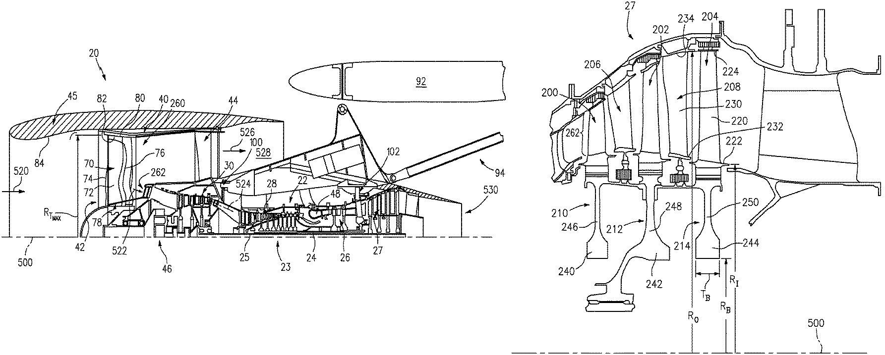
FIG. 1 shows a turbofan engine 20 having a main housing (engine case) 22 containing a rotor shaft assembly 23. An exemplary engine is a high-bypass turbofan. In such an engine, the normal cruise condition bypass area ratio of air mass flowing outside the case 22 (e.g., the compressor sections and combustor) to air mass passing through the case 22 is typically in excess of about 4.0 and, more narrowly, typically between about 4.0 and about 12.0. Via high 24 and low 25 shaft portions of the shaft assembly 23, a high pressure turbine section (gas generating turbine) 26 and a low pressure turbine section 27 respectively drive a high pressure compressor section 28 and a low pressure compressor section 30. As used herein, the high pressure turbine section experiences higher pressures that the low pressure turbine section. A low pressure turbine section is a section that powers a fan 42. Although a two-spool (plus fan) engine is shown, one of many alternative variations involves a three-spool (plus fan) engine wherein an intermediate spool comprises an intermediate pressure compressor between the low fan and high pressure compressor section and an intermediate pressure turbine between the high pressure turbine section and low pressure turbine section.
The engine extends along a longitudinal axis 500 from a fore end to an aft end. Adjacent the fore end, a shroud (fan case) 40 encircles the fan 42 and is supported by vanes 44. An aerodynamic nacelle around the fan case is shown and an aerodynamic nacelle 45 around the engine case is shown.
The low shaft portion 25 of the rotor shaft assembly 23 drives the fan 42 through a speed reduction mechanism 46. An exemplary speed reduction mechanism is an epicyclic transmission, namely a star or planetary gear system. As is discussed further below, an inlet airflow 520 entering the nacelle is divided into a portion 522 passing along a core flowpath 524 and a bypass portion 526 passing along a bypass flowpath 528. With the exception of diversions such as cooling air, etc., flow along the core flowpath sequentially passes through the low pressure compressor section, high pressure compressor section, a combustor 48, the high pressure turbine section, and the low pressure turbine section before exiting from an outlet 530.
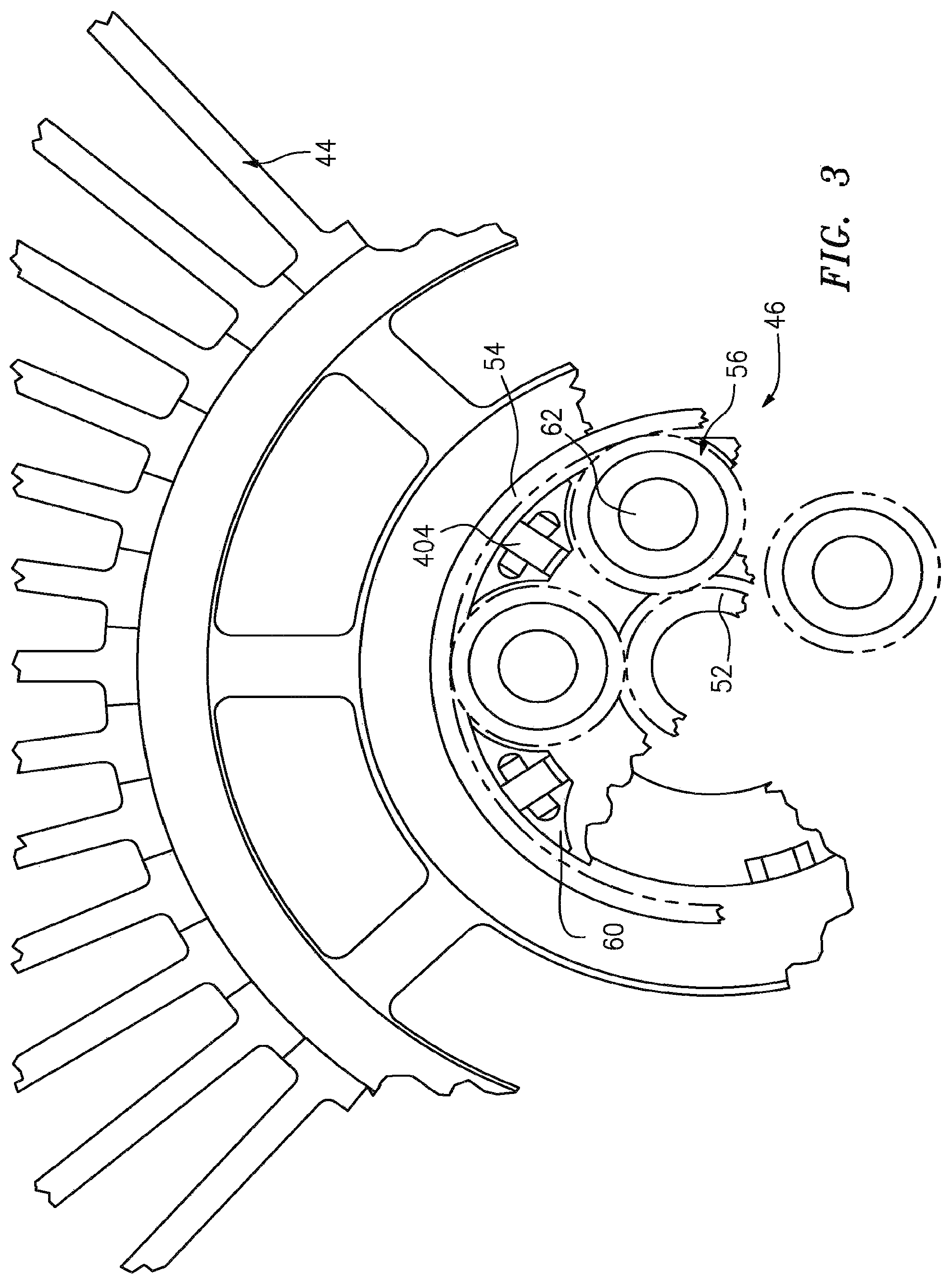
FIG. 3 schematically shows details of the transmission 46. A forward end of the low shaft 25 is coupled to a sun gear 52 (or other high speed input to the speed reduction mechanism). The externally-toothed sun gear 52 is encircled by a number of externally-toothed star gears 56 and an internally-toothed ring gear 54. The exemplary ring gear is coupled to the fan to rotate with the fan as a unit.
The star gears 56 are positioned between and enmeshed with the sun gear and ring gear. A cage or star carrier assembly 60 carries the star gears via associated journals 62. The exemplary star carrier is substantially irrotatably mounted relative via fingers 404 to the case 22.
Another transmission/gearbox combination has the star carrier connected to the fan and the ring is fixed to the fixed structure (case) is possible and such is commonly referred to as a planetary gearbox.
The speed reduction ratio is determined by the ratio of diameters within the gearbox. An exemplary reduction is between about 2:1 and about 13:1.
The exemplary fan (FIG. 1) comprises a circumferential array of blades 70. Each blade comprises an airfoil 72 having a leading edge 74 and a trailing edge 76 and extending from an inboard end 78 at a platform to an outboard end 80 (i.e., a free tip). The outboard end 80 is in close facing proximity to a rub strip 82 along an interior surface 84 of the nacelle and fan case.
To mount the engine to the aircraft wing 92, a pylon 94 is mounted to the fan case and/or to the other engine cases. The exemplary pylon 94 may be as disclosed in U.S. patent application Ser. No. 11/832,107 (US2009/0056343A1). The pylon comprises a forward mount 100 and an aft/rear mount 102. The forward mount may engage the engine intermediate case (IMC) and the aft mount may engage the engine thrust case. The aft mount reacts at least a thrust load of the engine.
To reduce aircraft fuel burn with turbofans, it is desirable to produce a low pressure turbine with the highest efficiency and lowest weight possible. Further, there are considerations of small size (especially radial size) that benefit the aerodynamic shape of the engine cowling and allow room for packaging engine subsystems.
FIG. 2 shows the low pressure turbine section 27 as comprising an exemplary three blade stages 200, 202, 204. An exemplary blade stage count is 2-6, more narrowly, 2-4, or 2-3, 3-5, or 3-4. Interspersed between the blade stages are vane stages 206 and 208. Each exemplary blade stage comprises a disk 210, 212, and 214, respectively. A circumferential array of blades extends from peripheries of each of the disks. Each exemplary blade comprises an airfoil 220 extending from an inner diameter (ID) platform 222 to an outer diameter (OD) shroud 224 (shown integral with the airfoil
An alternative may be an unshrouded blade with a rotational gap between the tip of the blade and a stationary blade outer air seal (BOAS). Each exemplary shroud 224 has outboard sealing ridges which seal with abradable seals (e.g., honeycomb) fixed to the case. The exemplary vanes in stages 206 and 208 include airfoils 230 extending from ID platforms 232 to OD shrouds 234. The exemplary OD shrouds 234 are directly mounted to the case. The exemplary platforms 232 carry seals for sealing with inter-disk knife edges protruding outwardly from inter-disk spacers which may be separate from the adjacent disks or unitarily formed with one of the adjacent disks.
Each exemplary disk 210, 212, 214 comprises an enlarged central annular protuberance or "bore" 240, 242, 244 and a thinner radial web 246, 248, 250 extending radially outboard from the bore. The bore imparts structural strength allowing the disk to withstand centrifugal loading which the disk would otherwise be unable to withstand.
A turbofan engine is characterized by its bypass ratio (mass flow ratio of air bypassing the core to air passing through the core) and the geometric bypass area ratio (ratio of fan duct annulus area outside/outboard of the low pressure compressor section inlet (i.e., at location 260 in FIG. 1) to low pressure compressor section inlet annulus area (i.e., at location 262 in FIG. 2). High bypass engines typically have bypass area ratio of at least four. There has been a correlation between increased bypass area ratio and increased low pressure turbine section radius and low pressure turbine section airfoil count. As is discussed below, this correlation may be broken by having an engine with relatively high bypass area ratio and relatively low turbine size.
By employing a speed reduction mechanism (e.g., a transmission) to allow the low pressure turbine section to turn very fast relative to the fan and by employing low pressure turbine section design features for high speed, it is possible to create a compact turbine module (e.g., while producing the same amount of thrust and increasing bypass area ratio). The exemplary transmission is a epicyclic transmission. Alternative transmissions include composite belt transmissions, metal chain belt transmissions, fluidic transmissions, and electric means (e.g., a motor/generator set where the turbine turns a generator providing electricity to an electric motor which drives the fan).
Compactness of the turbine is characterized in several ways. Along the compressor and turbine sections, the core gaspath extends from an inboard boundary (e.g., at blade hubs or outboard surfaces of platforms of associated blades and vanes) to an outboard boundary (e.g., at blade tips and inboard surfaces of blade outer air seals for unshrouded blade tips and at inboard surfaces of OD shrouds of shrouded blade tips and at inboard surfaces of OD shrouds of the vanes). These boundaries may be characterized by radii R.sub.I and R.sub.O, respectively, which vary along the length of the engine.
For low pressure turbine radial compactness, there may be a relatively high ratio of radial span (R.sub.O-R.sub.I) to radius (R.sub.O or R.sub.I). Radial compactness may also be expressed in the hub-to-tip ratio (R.sub.I:R.sub.O). These may be measured at the maximum R.sub.O location in the low pressure turbine section. The exemplary compact low pressure turbine section has a hub-to-tip ratio close to about 0.5 (e.g., about 0.4-0.5 or about 0.42-0.48, with an exemplary about 0.46).
Another characteristic of low pressure turbine radial compactness is relative to the fan size. An exemplary fan size measurement is the maximum tip radius R.sub.Tmax. of the fan blades. An exemplary ratio is the maximum R.sub.O along the low pressure turbine section to R.sub.Tmax. of the fan blades. Exemplary values for this ratio are less than about 0.55 (e.g., about 0.35-55), more narrowly, less than about 0.50, or about 0.35-0.50.
To achieve compactness the designer may balance multiple physical phenomena to arrive at a system solution as defined by the low pressure turbine hub-to-tip ratio, the fan maximum tip radius to low pressure turbine maximum R.sub.O ratio, the bypass area ratio, and the bypass area ratio to low pressure turbine airfoil count ratio. These concerns include, but are not limited to: a) aerodynamics within the low pressure turbine, b) low pressure turbine blade structural design, c) low pressure turbine disk structural design, and d) the shaft connecting the low pressure turbine to the low pressure compressor and speed reduction device between the low pressure compressor and fan. These physical phenomena may be balanced in order to achieve desirable performance, weight, and cost characteristics.
The addition of a speed reduction device between the fan and the low pressure compressor creates a larger design space because the speed of the low pressure turbine is decoupled from the fan. This design space provides great design variables and new constraints that limit feasibility of a design with respect to physical phenomena. For example the designer can independently change the speed and flow area of the low pressure turbine to achieve optimal aerodynamic parameters defined by flow coefficient (axial flow velocity/wheel speed) and work coefficient (wheel speed/square root of work). However, this introduces structural constraints with respect blade stresses, disk size, material selection, etc.
In some examples, the designer can choose to make low pressure turbine section disk bores much thicker relative to prior art turbine bores and the bores may be at a much smaller radius R.sub.B. This increases the amount of mass at less than a "self sustaining radius". Another means is to choose disk materials of greater strength than prior art such as the use of wrought powdered metal disks to allow for extremely high centrifugal blade pulls associated with the compactness.
Another variable in achieving compactness is to increase the structural parameter AN.sup.2 which is the annulus area of the exit of the low pressure turbine divided by the low pressure turbine rpm squared at its redline or maximum speed. Relative to prior art turbines, which are greatly constrained by fan blade tip mach number, a very wide range of AN.sup.2 values can be selected and optimized while accommodating such constraints as cost or a countering, unfavorable trend in low pressure turbine section shaft dynamics. In selecting the turbine speed (and thereby selecting the transmission speed ratio, one has to be mindful that at too high a gear ratio the low pressure turbine section shaft (low shaft) will become dynamically unstable.
The higher the design speed, the higher the gear ratio will be and the more massive the disks will become and the stronger the low pressure turbine section disk and blade material will have to be. All of these parameters can be varied simultaneously to change the weight of the turbine, its efficiency, its manufacturing cost, the degree of difficulty in packaging the low pressure turbine section in the core cowling and its durability. This is distinguished from a prior art direct drive configuration, where the high bypass area ratio can only be achieved by a large low pressure turbine section radius. Because that radius is so very large and, although the same variables (airfoil turning, disk size, blade materials, disk shape and materials, etc.) are theoretically available, as a practical matter economics and engine fuel burn considerations severely limit the designer's choice in these parameters.
Another characteristic of low pressure turbine section size is airfoil count (numerical count of all of the blades and vanes in the low pressure turbine). Airfoil metal angles can be selected such that airfoil count is low or extremely low relative to a direct drive turbine. In known prior art engines having bypass area ratio above 6.0 (e.g. 8.0-20), low pressure turbine sections involve ratios of airfoil count to bypass area ratio above 190.
With the full range of selection of parameters discussed above including, disk bore thickness, disk material, hub to tip ratio, and R.sub.O/R.sub.Tmax., the ratio of airfoil count to bypass area ratio may be below about 170 to as low as 10. (e.g., below about 150 or an exemplary about 10-170, more narrowly about 10-150). Further, in such embodiments the airfoil count may be below about 1700, or below about 1600.
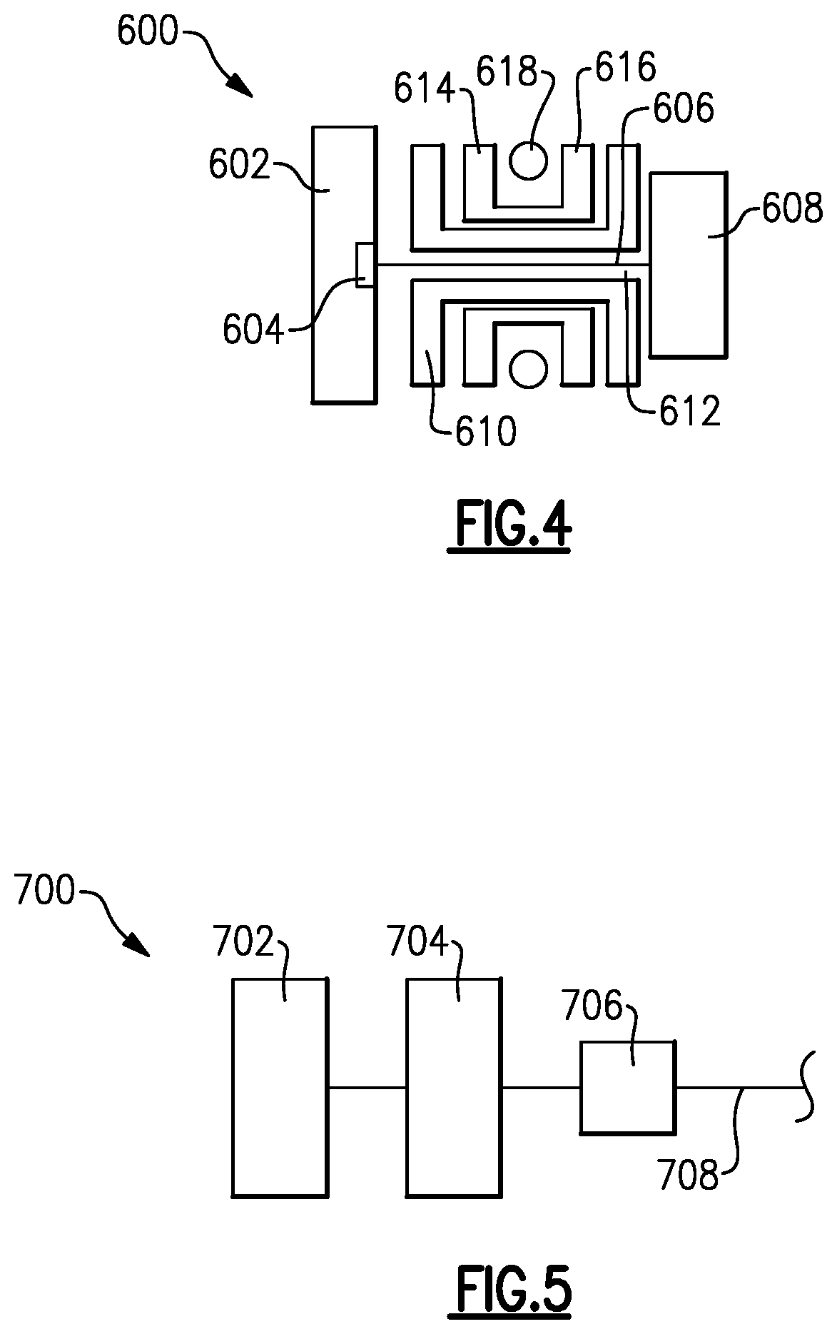
FIG. 4 shows an embodiment 600, wherein there is a fan drive turbine 608 driving a shaft 606 to in turn drive a fan rotor 602. A gear reduction 604 may be positioned between the fan drive turbine 608 and the fan rotor 602. This gear reduction 604 may be structured and operate like the gear reduction disclosed above. A compressor rotor 610 is driven by an intermediate pressure turbine 612, and a second stage compressor rotor 614 is driven by a turbine rotor 216. A combustion section 618 is positioned intermediate the compressor rotor 614 and the turbine section 616.
FIG. 5 shows yet another embodiment 700 wherein a fan rotor 702 and a first stage compressor 704 rotate at a common speed. The gear reduction 706 (which may be structured as disclosed above) is intermediate the compressor rotor 704 and a shaft 708 which is driven by a low pressure turbine section.
One or more embodiments have been described. Nevertheless, it will be understood that various modifications may be made. For example, when reengineering from a baseline engine configuration, details of the baseline may influence details of any particular implementation. Accordingly, other embodiments are within the scope of the following claims.
* * * * *
References
-
scribd.com/document/153900429/GasTurb-12
-
cgabusinessdesk.com/document/aviation_tech_review.pdf
-
catalog.wshampshire.com/Asset/psg_teflon_ptfe.pdf
-
bloomberg.com/news/articles/2016-06-30/ge-wins-shot-to-invalidate-pratt-airplane-engine-patent-in-u-s
-
geaviation.com/sites/default/files/datasheet-CF6-80C2.pdf
-
geaviation.com/commercial/engines/ge90-engine
-
-
-
-
mmsonline.com/articles/composite-fan-blade-containment-casepp
-
pyrografproducts.com/Merchant5/merchant.mvc?Screen=cp_nanofiber
-
smartcockpit.com/docs/F900EX-Engines.pdfpp
-
wiki.scramble.nl/index.php?title=General_Electric_F101#F101-GE-100
-
i-a-e.com/wp-content/uploads/2012/03/facts.pdfJun
-
ctr-sgi1.stanford.edu/CITS/ge90.htmldownloadedJun
-
design.ae.utexas.edu/subject/work/TFE731_4.jpgdownloadedJun
-
epower-propulsion.com/epower/gallery/ABP-RR%20Trent%20800%20cutaway.htmdownloadedJun
-
web.mit.edu/aeroastro/labs/gtl/early_GT_history_htmldownloadedJun
-
perso.ovh.net/.about.caeaxtke/fr/coll/falcon50_5.htmldownloadedJun
-
hackedgadgets.com/2011/08/02/how-to-build-a-rolls-royce-trent-1000-jet-engine-used-in-the-boeing-787/downloadedJun
-
warandtactics.com/smf/planet-earth-the-serious-stuff-non-mil-news/a-380-emergency-landing!/downloadedJun
-
flightglobal.com/airspace/media/aeroenginesjetcutaways/avco-lycoming-alf502r-2-cutaway-5582.aspx
-
reuters.com/article/us-general-electric-united-tech-engine/ge-exec-says-avoided-geared-design-in-jet-engine-battle-with-pratt-idUSKBN0HA2H620140915
D00000
D00001
D00002
D00003
D00004
XML
uspto.report is an independent third-party trademark research tool that is not affiliated, endorsed, or sponsored by the United States Patent and Trademark Office (USPTO) or any other governmental organization. The information provided by uspto.report is based on publicly available data at the time of writing and is intended for informational purposes only.
While we strive to provide accurate and up-to-date information, we do not guarantee the accuracy, completeness, reliability, or suitability of the information displayed on this site. The use of this site is at your own risk. Any reliance you place on such information is therefore strictly at your own risk.
All official trademark data, including owner information, should be verified by visiting the official USPTO website at www.uspto.gov. This site is not intended to replace professional legal advice and should not be used as a substitute for consulting with a legal professional who is knowledgeable about trademark law.