Heated dosing mixer
Rohde , et al. September 29, 2
U.S. patent number 10,787,946 [Application Number 16/135,211] was granted by the patent office on 2020-09-29 for heated dosing mixer. This patent grant is currently assigned to Faurecia Emissions Control Technologies, USA, LLC. The grantee listed for this patent is Faurecia Emissions Control Technologies, USA, LLC. Invention is credited to Madhuri Gandikota, John G. Rohde.


| United States Patent | 10,787,946 |
| Rohde , et al. | September 29, 2020 |
Heated dosing mixer
Abstract
A vehicle exhaust system includes a mixer housing that has a doser opening and defines an internal mixing chamber. A doser injects fluid into the mixer housing through the doser opening. A flow passage has an inlet end positioned adjacent the doser opening and an outlet end open to the mixing chamber. At least one heating device associated with the flow passage.
| Inventors: | Rohde; John G. (Columbus, IN), Gandikota; Madhuri (Columbus, IN) | ||||||||||
|---|---|---|---|---|---|---|---|---|---|---|---|
| Applicant: |
|
||||||||||
| Assignee: | Faurecia Emissions Control
Technologies, USA, LLC (Columbus, IN) |
||||||||||
| Family ID: | 1000005082114 | ||||||||||
| Appl. No.: | 16/135,211 | ||||||||||
| Filed: | September 19, 2018 |
Prior Publication Data
| Document Identifier | Publication Date | |
|---|---|---|
| US 20200088081 A1 | Mar 19, 2020 | |
| Current U.S. Class: | 1/1 |
| Current CPC Class: | F01N 3/2892 (20130101); F01N 3/208 (20130101); F01N 3/2066 (20130101); F01N 2610/146 (20130101); F01N 2240/20 (20130101); F01N 2240/16 (20130101); F01N 2610/02 (20130101) |
| Current International Class: | F01N 3/20 (20060101); F01N 3/28 (20060101) |
References Cited [Referenced By]
U.S. Patent Documents
| 1462219 | July 1923 | Wagner |
| 3150922 | September 1964 | Ashley |
| 3524631 | August 1970 | Mare |
| 4033123 | July 1977 | Masaki et al. |
| 4054418 | October 1977 | Miller et al. |
| 4094934 | June 1978 | Tuckey et al. |
| 4420933 | December 1983 | Kajitani et al. |
| 4459805 | July 1984 | Kamiya et al. |
| 4538413 | September 1985 | Shinzawa et al. |
| 4576617 | March 1986 | Renevot |
| 4662172 | May 1987 | Shinzawa et al. |
| 4912920 | April 1990 | Hirabayashi |
| 5020991 | June 1991 | Schaale et al. |
| 5605042 | February 1997 | Stutzenberger |
| 5606856 | March 1997 | Linder et al. |
| 5648022 | July 1997 | Gohara et al. |
| 5826428 | October 1998 | Blaschke |
| 6192677 | February 2001 | Tost |
| 6382600 | May 2002 | Mahr |
| 6401455 | June 2002 | Mathes et al. |
| 6444177 | September 2002 | Muller et al. |
| 6449947 | September 2002 | Liu et al. |
| 6460340 | October 2002 | Chauvette et al. |
| 6513323 | February 2003 | Weigl et al. |
| 6516610 | February 2003 | Hodgson |
| 6527865 | March 2003 | Sajoto et al. |
| 6539708 | April 2003 | Hofmann et al. |
| 6637196 | October 2003 | Tost |
| 6722123 | April 2004 | Liu et al. |
| 6755014 | June 2004 | Kawai et al. |
| 7059118 | June 2006 | Ripper et al. |
| 7509799 | March 2009 | Amou et al. |
| 7730721 | June 2010 | Kimura et al. |
| 7784273 | August 2010 | Kanaya et al. |
| 7814745 | October 2010 | Levin et al. |
| 7849676 | December 2010 | Witte-Merl |
| 7895828 | March 2011 | Satou |
| 7963104 | June 2011 | Girard et al. |
| 7980063 | July 2011 | Cooke |
| 7992379 | August 2011 | Suzuki et al. |
| 8006487 | August 2011 | Gaiser |
| 8033101 | October 2011 | Amon et al. |
| 8079211 | December 2011 | Levin et al. |
| 8097055 | January 2012 | Staley et al. |
| 8114364 | February 2012 | Harinath et al. |
| 8173088 | May 2012 | Makartchouk et al. |
| 8216537 | July 2012 | Kouvetakis et al. |
| 8240137 | August 2012 | Liu et al. |
| 8250859 | August 2012 | Torisaka et al. |
| 8371114 | February 2013 | Hayashi et al. |
| 8371256 | February 2013 | Durrett et al. |
| 8393834 | March 2013 | Brugman |
| 8397492 | March 2013 | Kowada |
| 8425851 | April 2013 | Kimura |
| 8438839 | May 2013 | Floyd et al. |
| 8499739 | August 2013 | Cox et al. |
| 8539761 | September 2013 | Lebas et al. |
| 8607550 | December 2013 | Tangemann et al. |
| 8622316 | January 2014 | Haeberer et al. |
| 8646258 | February 2014 | Vanvolsem et al. |
| 8661792 | March 2014 | Greber et al. |
| 8677738 | March 2014 | Floyd et al. |
| 8700246 | April 2014 | Kurikuma et al. |
| 8726643 | May 2014 | Way et al. |
| 8756921 | June 2014 | Troxler et al. |
| 8776509 | July 2014 | Wikaryasz et al. |
| 8893481 | November 2014 | Katou et al. |
| 8899026 | December 2014 | Loman et al. |
| 8915069 | December 2014 | Loman |
| 8916101 | December 2014 | Iljima et al. |
| 8955312 | February 2015 | Watahiki et al. |
| 8966884 | March 2015 | Kruse et al. |
| 8991160 | March 2015 | Katou et al. |
| 9003775 | April 2015 | Wright et al. |
| 9003782 | April 2015 | Werni et al. |
| 9057312 | June 2015 | Munnannur et al. |
| 9062582 | June 2015 | Loman et al. |
| 9062589 | June 2015 | Katou et al. |
| 9103258 | August 2015 | Norling et al. |
| 9140163 | September 2015 | Loman |
| 9145810 | September 2015 | Bisaiji et al. |
| 9188039 | November 2015 | Nagel et al. |
| 9194267 | November 2015 | Loman |
| 9266075 | February 2016 | Chapman et al. |
| 9289724 | March 2016 | Stanavich et al. |
| 9308495 | April 2016 | Kimura |
| 9341100 | May 2016 | Petry |
| 9346017 | May 2016 | Greber |
| 9364790 | June 2016 | Sampath et al. |
| 9394821 | July 2016 | Assalve et al. |
| 9410464 | August 2016 | Hicks et al. |
| 9422844 | August 2016 | Suzuki et al. |
| 9441522 | September 2016 | Crandell et al. |
| 9464546 | October 2016 | Perrot et al. |
| 9494067 | November 2016 | Niaz |
| 9518496 | December 2016 | Hill et al. |
| 9587543 | March 2017 | Haverkamp et al. |
| 9670811 | June 2017 | De Rudder et al. |
| 9714598 | July 2017 | Alano et al. |
| 9719397 | August 2017 | Alano et al. |
| 9726064 | August 2017 | Alano |
| 9810127 | November 2017 | Kloeckner et al. |
| 9849424 | December 2017 | Davidson et al. |
| 9890682 | February 2018 | Clayton, Jr. |
| 9920676 | March 2018 | Freeman et al. |
| 2001/0018826 | September 2001 | Rusch |
| 2003/0110763 | June 2003 | Pawson et al. |
| 2003/0226412 | December 2003 | Rumminger et al. |
| 2004/0047232 | March 2004 | Terentiev |
| 2005/0150211 | July 2005 | Crawley et al. |
| 2006/0070374 | April 2006 | Gaiser et al. |
| 2006/0218902 | October 2006 | Arellano et al. |
| 2007/0092143 | April 2007 | Higgins |
| 2007/0092413 | April 2007 | Hirata et al. |
| 2007/0163241 | July 2007 | Meingast et al. |
| 2007/0175204 | August 2007 | Shirai et al. |
| 2007/0193252 | August 2007 | McKinley et al. |
| 2008/0011777 | January 2008 | Cooke |
| 2008/0022663 | January 2008 | Dodge |
| 2008/0022670 | January 2008 | Ichikawa |
| 2008/0092526 | April 2008 | Kunkel et al. |
| 2008/0141667 | June 2008 | Winter et al. |
| 2008/0256931 | October 2008 | Kawakita et al. |
| 2008/0282687 | November 2008 | Park et al. |
| 2008/0295497 | December 2008 | Kornherr et al. |
| 2009/0012066 | January 2009 | Izumo et al. |
| 2009/0031714 | February 2009 | Jochumsen et al. |
| 2009/0044524 | February 2009 | Fujino |
| 2009/0064668 | March 2009 | Herrick et al. |
| 2009/0084094 | April 2009 | Goss et al. |
| 2009/0107126 | April 2009 | Bugos et al. |
| 2009/0120066 | May 2009 | VanderGriend et al. |
| 2009/0127511 | May 2009 | Bruck et al. |
| 2009/0249769 | October 2009 | Flanagan et al. |
| 2010/0000203 | January 2010 | Kowada |
| 2010/0005790 | January 2010 | Zhang |
| 2010/0005791 | January 2010 | Ranganathan et al. |
| 2010/0071355 | March 2010 | Brown et al. |
| 2010/0101222 | April 2010 | Oesterle et al. |
| 2010/0146950 | June 2010 | Hayashi et al. |
| 2010/0186393 | July 2010 | Kowada |
| 2010/0196225 | August 2010 | Harinath et al. |
| 2010/0199645 | August 2010 | Telford |
| 2010/0212292 | August 2010 | Rusch et al. |
| 2010/0212301 | August 2010 | De Rudder et al. |
| 2010/0257849 | October 2010 | Kowada |
| 2010/0263359 | October 2010 | Haverkamp et al. |
| 2010/0300080 | December 2010 | Peters et al. |
| 2010/0307138 | December 2010 | Chen |
| 2010/0319329 | December 2010 | Khadiya |
| 2011/0036082 | February 2011 | Collinot |
| 2011/0041488 | February 2011 | Bisaiji et al. |
| 2011/0061374 | March 2011 | Noritake |
| 2011/0079003 | April 2011 | Sun et al. |
| 2011/0107743 | May 2011 | Ranganathan et al. |
| 2011/0107749 | May 2011 | Tsujimoto et al. |
| 2011/0113759 | May 2011 | Tilinski et al. |
| 2011/0113764 | May 2011 | Salanta et al. |
| 2011/0126529 | June 2011 | Park |
| 2011/0131958 | June 2011 | Adelman et al. |
| 2011/0162347 | July 2011 | Katare et al. |
| 2011/0167810 | July 2011 | Lebas et al. |
| 2011/0239631 | October 2011 | Bui et al. |
| 2011/0257849 | October 2011 | Alberius et al. |
| 2011/0274590 | November 2011 | Floyd et al. |
| 2012/0174561 | July 2012 | Troxler et al. |
| 2012/0204541 | August 2012 | Li et al. |
| 2012/0216513 | August 2012 | Greber et al. |
| 2012/0322012 | December 2012 | Tsumagari et al. |
| 2012/0324872 | December 2012 | Jaruvatee et al. |
| 2013/0164181 | June 2013 | Ilijima et al. |
| 2013/0164182 | June 2013 | Iijima et al. |
| 2013/0164183 | June 2013 | Iijima et al. |
| 2013/0170973 | July 2013 | Staskowiak et al. |
| 2013/0216442 | August 2013 | Brunel et al. |
| 2013/0239546 | September 2013 | Levin et al. |
| 2013/0263575 | October 2013 | Sun |
| 2013/0269325 | October 2013 | Hadden et al. |
| 2013/0291519 | November 2013 | Patel et al. |
| 2013/0303365 | November 2013 | Yin et al. |
| 2014/0093439 | April 2014 | De Rudder et al. |
| 2014/0230418 | August 2014 | Perrot et al. |
| 2014/0318112 | October 2014 | Solbrig et al. |
| 2014/0325967 | November 2014 | Kimura |
| 2014/0334987 | November 2014 | Stanavich et al. |
| 2014/0334988 | November 2014 | Stanavich et al. |
| 2015/0004083 | January 2015 | Makartchouk et al. |
| 2015/0040547 | February 2015 | Brockman et al. |
| 2015/0047329 | February 2015 | Way et al. |
| 2015/0071826 | March 2015 | Sampath et al. |
| 2015/0101313 | April 2015 | Mitchell et al. |
| 2015/0152766 | June 2015 | Brunel |
| 2015/0240689 | August 2015 | Guilbaud et al. |
| 2015/0267596 | September 2015 | Tobben |
| 2015/0290585 | October 2015 | Nagata et al. |
| 2015/0315943 | November 2015 | Gschwind |
| 2015/0354432 | December 2015 | Gehrlein et al. |
| 2015/0361853 | December 2015 | Nagata et al. |
| 2016/0032808 | February 2016 | Kobe et al. |
| 2016/0084133 | March 2016 | Sampath et al. |
| 2016/0115847 | April 2016 | Chapman et al. |
| 2016/0129397 | May 2016 | Lee et al. |
| 2016/0131007 | May 2016 | Kauderer et al. |
| 2016/0138454 | May 2016 | Alano et al. |
| 2016/0184783 | June 2016 | Tyni et al. |
| 2016/0201539 | July 2016 | Tongu et al. |
| 2016/0215673 | July 2016 | Noren, IV et al. |
| 2016/0251990 | September 2016 | Dimpelfeld et al. |
| 2016/0319720 | November 2016 | Alano |
| 2016/0332126 | November 2016 | Nande et al. |
| 2016/0348557 | December 2016 | Dalimonte et al. |
| 2016/0361694 | December 2016 | Brandl et al. |
| 2017/0066012 | March 2017 | Hornback |
| 2017/0082007 | March 2017 | Alano et al. |
| 2017/0107877 | April 2017 | Johnson et al. |
| 2017/0167344 | June 2017 | Alano et al. |
| 2017/0175606 | June 2017 | Peace |
| 2018/0023446 | January 2018 | Dimpelfeld |
| 2018/0080360 | March 2018 | Kurpejovic |
| 2018/0142597 | May 2018 | Riepshoff et al. |
| 2018/0156092 | June 2018 | Inclan et al. |
| 2018/0171849 | June 2018 | Saupe et al. |
| 101732992 | Jun 2010 | CN | |||
| 202012386 | Oct 2011 | CN | |||
| 202360191 | Aug 2012 | CN | |||
| 202467984 | Oct 2012 | CN | |||
| 203452874 | Feb 2014 | CN | |||
| 205164443 | Apr 2016 | CN | |||
| 106014560 | Oct 2016 | CN | |||
| 205627632 | Oct 2016 | CN | |||
| 4417238 | Sep 1994 | DE | |||
| 10241697 | Apr 2003 | DE | |||
| 10312212 | Nov 2003 | DE | |||
| 102005061145 | Jun 2007 | DE | |||
| 102007034316 | Jan 2009 | DE | |||
| 102008023585 | Jan 2009 | DE | |||
| 102007051510 | Apr 2009 | DE | |||
| 202008001022 | Jun 2009 | DE | |||
| 102008008563 | Aug 2009 | DE | |||
| 102007052262 | Feb 2010 | DE | |||
| 102008040476 | Feb 2010 | DE | |||
| 102008041486 | Feb 2010 | DE | |||
| 102008052757 | Apr 2010 | DE | |||
| 102008059602 | Jun 2010 | DE | |||
| 102009046280 | May 2011 | DE | |||
| 102011008895 | Jul 2012 | DE | |||
| 102011075594 | Nov 2012 | DE | |||
| 102011077156 | Dec 2012 | DE | |||
| 102012209689 | Dec 2013 | DE | |||
| 102013012909 | Feb 2015 | DE | |||
| 102014104224 | Oct 2015 | DE | |||
| 0268026 | May 1988 | EP | |||
| 0956895 | Nov 1999 | EP | |||
| 1314864 | May 2003 | EP | |||
| 1596044 | Nov 2005 | EP | |||
| 2221459 | Aug 2010 | EP | |||
| 2405109 | Jan 2012 | EP | |||
| 2465602 | Jun 2012 | EP | |||
| 2492465 | Aug 2012 | EP | |||
| 2551481 | Jan 2013 | EP | |||
| 2687286 | Jan 2014 | EP | |||
| 2860369 | Apr 2015 | EP | |||
| 2860370 | Apr 2015 | EP | |||
| 2873157 | Jan 2006 | FR | |||
| 2897646 | Aug 2007 | FR | |||
| 2910533 | Jun 2008 | FR | |||
| 2965011 | Mar 2012 | FR | |||
| 2977632 | Jan 2013 | FR | |||
| 3004755 | Oct 2014 | FR | |||
| 3007068 | Dec 2014 | FR | |||
| 174131 | Jan 1922 | GB | |||
| 1215148 | Dec 1970 | GB | |||
| 2537061 | Oct 2016 | GB | |||
| H0296212 | Apr 1990 | JP | |||
| H04365303 | Dec 1992 | JP | |||
| H11159320 | Jun 1999 | JP | |||
| 2001030093 | Feb 2001 | JP | |||
| 2004339991 | Dec 2004 | JP | |||
| 2005127271 | May 2005 | JP | |||
| 2005155404 | Jun 2005 | JP | |||
| 2005214175 | Aug 2005 | JP | |||
| 2005273578 | Oct 2005 | JP | |||
| 2006017043 | Jan 2006 | JP | |||
| 2006167576 | Jun 2006 | JP | |||
| 2007000783 | Jan 2007 | JP | |||
| 2007000784 | Jan 2007 | JP | |||
| 2007040149 | Feb 2007 | JP | |||
| 2007073957 | Mar 2007 | JP | |||
| 2007115748 | May 2007 | JP | |||
| 2007146700 | Jun 2007 | JP | |||
| 2008014213 | Jan 2008 | JP | |||
| 2009002213 | Jan 2009 | JP | |||
| 2009030560 | Feb 2009 | JP | |||
| 2009114910 | May 2009 | JP | |||
| 2009156068 | Jul 2009 | JP | |||
| 2009156069 | Jul 2009 | JP | |||
| 2009167806 | Jul 2009 | JP | |||
| 2009209822 | Sep 2009 | JP | |||
| 5066435 | Nov 2012 | JP | |||
| 5114219 | Jan 2013 | JP | |||
| 2013002367 | Jan 2013 | JP | |||
| 2014095367 | May 2014 | JP | |||
| 2016188579 | Nov 2016 | JP | |||
| 100679716 | Jan 2007 | KR | |||
| 20090105593 | Oct 2009 | KR | |||
| 102013086287 | Apr 2010 | KR | |||
| 20110049152 | May 2011 | KR | |||
| 10-2014-0002326 | Jan 2014 | KR | |||
| 8200991 | Aug 1983 | SE | |||
| 531199 | Jan 2009 | SE | |||
| 2004113690 | Dec 2004 | WO | |||
| 2008034981 | Mar 2008 | WO | |||
| 2008049757 | May 2008 | WO | |||
| 2008122724 | Oct 2008 | WO | |||
| 2009012819 | Jan 2009 | WO | |||
| 2009024815 | Feb 2009 | WO | |||
| 2009030858 | Mar 2009 | WO | |||
| 2009098096 | Aug 2009 | WO | |||
| 2009127449 | Oct 2009 | WO | |||
| 2010055239 | May 2010 | WO | |||
| 2010149410 | Dec 2010 | WO | |||
| 2011110885 | Sep 2011 | WO | |||
| 2012052560 | Apr 2012 | WO | |||
| 2012120000 | Sep 2012 | WO | |||
| 2013004517 | Jan 2013 | WO | |||
| 2013010700 | Jan 2013 | WO | |||
| 2013035112 | Mar 2013 | WO | |||
| 2013099312 | Jul 2013 | WO | |||
| 2013099313 | Jul 2013 | WO | |||
| 2014098728 | Jun 2014 | WO | |||
| 2015012829 | Jan 2015 | WO | |||
| 2015018849 | Feb 2015 | WO | |||
| 2015076765 | May 2015 | WO | |||
| 2015105500 | Jul 2015 | WO | |||
| 2015130640 | Sep 2015 | WO | |||
| 2015151282 | Oct 2015 | WO | |||
| 2016013319 | Jan 2016 | WO | |||
| 2016036298 | Mar 2016 | WO | |||
| 2016158993 | Oct 2016 | WO | |||
| 2017054179 | Apr 2017 | WO | |||
| 2017084549 | May 2017 | WO | |||
| 2017102813 | Jun 2017 | WO | |||
| 2018054490 | Mar 2018 | WO | |||
Attorney, Agent or Firm: Carlson, Gaskey & Olds, P.C.
Claims
The invention claimed is:
1. A vehicle exhaust system comprising: a mixer housing defining an internal mixing chamber, wherein the mixer housing includes a doser opening; an inlet baffle and an outlet baffle positioned within the mixer housing with the internal mixing chamber being positioned between the inlet and the outlet baffles, and wherein the doser opening is formed in the mixer housing between the inlet and outlet baffles; a doser to inject fluid into the mixer housing through the doser opening, wherein the fluid includes at least urea and water; a flow passage having an inlet end positioned adjacent the doser opening and an outlet end open to the mixing chamber, and wherein the flow passage is positioned within the internal mixing chamber between the inlet and outlet baffles; and at least one heating device associated with the flow passage.
2. The vehicle exhaust system according to claim 1 wherein the at least one heating device is an electric coil that heats a surface of the flow passage.
3. The vehicle exhaust system according to claim 1 wherein the flow passage comprises a cylindrical tube or cone, and wherein the inlet baffle includes at least one main inlet opening that receives a majority of exhaust gas entering the mixer housing and at least one additional opening that directs a portion of exhaust gas toward an outer surface of the flow passage.
4. The vehicle exhaust system according to claim 1 wherein the flow passage comprises a cylindrical tube or cone, and wherein the heating device heats a surface of the flow passage.
5. The vehicle exhaust system according to claim 1 wherein the flow passage comprises a solid or porous body, and wherein the flow passage comprises a cylindrical tube or cone.
6. The vehicle exhaust system according to claim 5 wherein the flow passage extends from a base end to a distal end, and wherein the base end of the flow passage is positioned adjacent the doser opening such that a gap is formed within the mixer housing between the base end of the flow passage and an inner surface of the mixer housing that surrounds the doser opening.
7. The vehicle exhaust system according to claim 6 wherein exhaust gas is directed into the base end of the flow passage to mix with fluid sprayed into the base end of the flow passage such that a mixture of evaporated fluid and exhaust gas exits the outlet end of the flow passage.
8. The vehicle exhaust system according to claim 1 wherein the at least one heating device is positioned at the outlet end of the flow passage.
9. The vehicle exhaust system according to claim 8 wherein the at least one heating device surrounds an outer surface of the flow passage.
10. The vehicle exhaust system according to claim 8 wherein an inner surface of the flow passage surrounds the at least one heating device.
11. The vehicle exhaust system according to claim 1 including a control that selectively activates the at least one heating device when a temperature of the exhaust gas is below a predetermined temperature.
12. The vehicle exhaust system according to claim 11 including at least one temperature sensor that measures exhaust gas temperature prior to entering the mixing chamber.
13. The vehicle exhaust system according to claim 11 wherein the at least one heating device heats the flow passage such that all fluid injected by the doser evaporates prior to entering the mixing chamber.
14. The vehicle exhaust system according to claim 11 wherein an amount of energy required to heat the flow passage is determined by the control based on an amount of injected fluid and the temperature of the exhaust gas.
15. A vehicle exhaust system comprising: a mixer housing defining an internal mixing chamber, wherein the mixer housing includes a doser opening; a doser to inject fluid into the mixer housing through the doser opening; a flow passage having an inlet end positioned adjacent the doser opening and an outlet end open to the mixing chamber; and at least one heating device associated with the flow passage, wherein the at least one heating device is a heated plate that heats a surface of the flow passage.
16. A vehicle exhaust system comprising: a mixer housing defining an internal mixing chamber, wherein the mixer housing includes a doser opening; an inlet baffle and an outlet baffle positioned within the mixer housing with the internal mixing chamber being positioned between the inlet and the outlet baffles, and wherein the doser opening is formed in the mixer housing between the inlet and outlet baffles; a doser to inject fluid into the mixer housing through the doser opening, wherein the fluid includes at least urea and water; a flow passage comprising a solid or porous body that has an inlet end positioned adjacent the doser opening and an outlet end open to the mixing chamber, and wherein the flow passage is positioned within the internal mixing chamber between the inlet and outlet baffles; at least one heating device positioned at the outlet end of the flow passage to heat the flow passage such that all fluid injected by the doser evaporates prior to entering the mixing chamber; and a control that selectively activates the at least one heating device when a temperature of the exhaust gas is below a predetermined temperature.
17. The vehicle exhaust system according to claim 16 wherein the at least one heating device comprises an electric coil or heated plate, and wherein the flow passage comprises a cylindrical tube or cone.
18. The vehicle exhaust system according to claim 16 wherein the flow passage comprises a cylindrical tube or cone, and wherein the inlet baffle includes at least one main inlet opening that receives a majority of exhaust gas entering the mixer housing and at least one additional opening that directs a portion of exhaust gas toward an outer surface of the flow passage, or wherein the heating device heats a surface of the flow passage.
19. A method for injecting a reducing agent into an exhaust component comprising the steps of: providing a mixer housing that defines an internal mixing chamber, and positioning an inlet baffle and an outlet baffle within the mixer housing with the internal mixing chamber being positioned between the inlet and the outlet baffles; providing a doser opening in the mixer housing between the inlet and outlet baffles; positioning a doser to inject fluid into the mixer housing through the doser opening, wherein the fluid includes at least urea and water; positioning a flow passage in the mixer housing such that an inlet end of the flow passage is positioned adjacent the doser opening and an outlet end of the flow passage is open to the mixing chamber; positioning the flow passage within the internal mixing chamber between the inlet an outlet baffles and; and using at least one heating device to heat the flow passage.
20. The method according to claim 19 wherein the flow passage comprises a cylindrical tube or cone, and including providing the inlet baffle with at least one main inlet opening that receives a majority of exhaust gas entering the mixer housing and at least one additional opening that directs a portion of exhaust gas toward an outer surface of the flow passage, or using the heating device to heat a surface of the flow passage.
21. The method according to claim 19 including heating the flow passage such that all fluid injected by the doser evaporates prior to entering the mixing chamber.
22. The method according to claim 21 including selectively activating the at least one heating device when a temperature of the exhaust gas is below a predetermined temperature.
Description
BACKGROUND OF THE INVENTION
An exhaust system includes catalyst components to reduce emissions. The exhaust system includes an injection system that injects a diesel exhaust fluid (DEF), or a reducing agent such as a solution of urea and water for example, upstream of a selective catalytic reduction (SCR) catalyst which is used to reduce NOx emissions. A mixer is positioned upstream of the SCR catalyst and mixes engine exhaust gases and products of urea transformation. The injection system includes a doser that sprays the fluid into the exhaust stream. The fluid spray should be transformed as much as possible into ammonia (NH.sub.3) before reaching the SCR catalyst.
Providing for ultra-low NOx emissions requires dosing at low temperatures to address reducing emissions at cold start and low load cycles. Dosing DEF at low temperatures is a thermolysis and deposit formation problem as there is insufficient heat. Some configurations require ammonia dosing by converting DEF to ammonia prior to introduction into the mixer. This requires storing ammonia and/or heating DEF external to the mixer. This is disadvantageous from a packaging and cost perspective.
SUMMARY OF THE INVENTION
In one exemplary embodiment, a vehicle exhaust system has a mixer housing that includes a doser opening and defines an internal mixing chamber. A doser injects fluid into the mixer housing through the doser opening. A flow passage has an inlet end positioned adjacent the doser opening and an outlet end open to the mixing chamber. At least one heating device associated with the flow passage.
In a further embodiment of the above, the heating device is an electric coil that heats a surface of the flow passage.
In a further embodiment of any of the above, the heating device is a heated plate that heats a surface of the flow passage.
In a further embodiment of any of the above, the heating device is positioned at the outlet end of the flow passage.
In a further embodiment of any of the above, the heating device surrounds an outer surface of the flow passage.
In a further embodiment of any of the above, an inner surface of the flow passage surrounds the heating device.
In a further embodiment of any of the above, the system includes a control that selectively activates the heating device when a temperature of the exhaust gas is below a predetermined temperature.
In a further embodiment of any of the above, the system includes at least one temperature sensor that measures exhaust gas temperature prior to entering the mixing chamber.
In a further embodiment of any of the above, the heating device heats the flow passage such that all fluid injected by the doser evaporates prior to entering the mixing chamber.
In a further embodiment of any of the above, an amount of energy required to heat the flow passage is determined based on an amount of injected fluid and the temperature of the exhaust gas.
In a further embodiment of any of the above, the flow passage comprises a solid or porous body, and wherein the flow passage further comprises a cylindrical tube or cone.
In a further embodiment of any of the above, the base end of the flow passage is positioned adjacent the dose opening such that a gap is formed within the mixer housing between the base end of the flow passage and an inner surface of the mixer housing that surrounds the doser opening.
In a further embodiment of any of the above, exhaust gas is directed into the base end of the flow passage to mix with fluid sprayed into the base end of the flow passage such that a mixture of evaporated fluid and exhaust gas exits the outlet end of the flow passage.
In another exemplary embodiment, a vehicle exhaust system includes a mixer housing, a doser to inject fluid into the mixer housing through a doser opening in the mixer housing, and a flow passage comprising a solid or porous body that has an inlet end positioned adjacent the doser opening and an outlet end open to the mixing chamber. At least one heating device is positioned at the outlet end of the flow passage to heat the flow passage such that all fluid injected by the doser evaporates prior to entering the mixing chamber. The system also includes a control that selectively activates the heating device when a temperature of the exhaust gas is below a predetermined temperature.
In a further embodiment of any of the above, the heating device comprises an electric coil or heated plate, and the flow passage comprises a cylindrical tube or cone.
In another exemplary embodiment, a method for injecting a reducing agent into an exhaust component comprising the steps of: providing a mixer housing that defines an internal mixing chamber; providing a doser opening in the mixer housing; positioning a doser to inject fluid into the mixer housing through the doser opening; positioning a flow passage in the mixer housing such that an inlet end of the flow passage is positioned adjacent the doser opening and an outlet end of the flow passage is open to the mixing chamber; and using at least one heating device to heat the flow passage.
In a further embodiment of any of the above, the method includes heating the flow passage such that all fluid injected by the doser evaporates prior to entering the mixing chamber.
In a further embodiment of any of the above, the method includes selectively activating the heating device when a temperature of the exhaust gas is below a predetermined temperature.
These and other features of this application will be best understood from the following specification and drawings, the following of which is a brief description.
BRIEF DESCRIPTION OF THE DRAWINGS
FIG. 1 schematically illustrates one example of an exhaust system with a mixer according to the subject invention.
FIG. 2 is an inlet end view of the mixer.
FIG. 3 is a section view of the mixer of FIG. 2.
FIG. 4 is a schematic side cross-sectional view of a flow passage as used in a doser sub-assembly.
FIG. 5 is one example of a flow passage with a heating device as used with the mixer of FIG. 2.
FIG. 6 is another example of a flow passage with a heating device.
FIG. 7 is another example of a flow passage with a heating device.
DETAILED DESCRIPTION
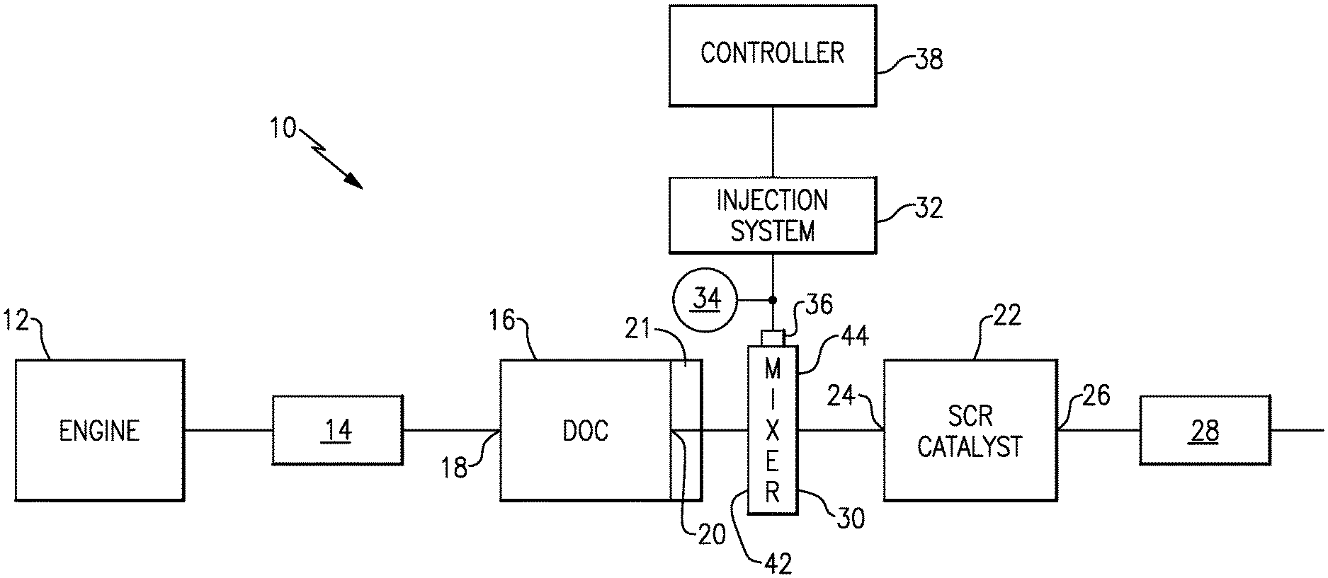
FIG. 1 shows a vehicle exhaust system 10 that conducts hot exhaust gases generated by an engine 12 through various upstream exhaust components 14 to reduce emission and control noise as known. The various upstream exhaust components 14 can include one or more of the following: pipes, filters, valves, catalysts, mufflers etc.
In one example configuration, the upstream exhaust component 14 comprises at least one pipe that directs engine exhaust gases into a diesel oxidation catalyst (DOC) 16 having an inlet 18 and an outlet 20. Downstream of the DOC 16 there may be a diesel particulate filter (DPF) 21 that is used to remove contaminants from the exhaust gas as known. Downstream of the DOC 16 and optional DPF 21 is a selective catalytic reduction (SCR) catalyst 22 having an inlet 24 and an outlet 26. The outlet 26 communicates exhaust gases to downstream exhaust components 28. Optionally, component 22 can comprise a catalyst that is configured to perform a selective catalytic reduction function and a particulate filter function. The various downstream exhaust components 28 can include one or more of the following: pipes, filters, valves, catalysts, mufflers etc. These upstream 14 and downstream 28 components can be mounted in various different configurations and combinations dependent upon vehicle application and available packaging space.
A mixer 30 is positioned downstream from the outlet 20 of the DOC 16 or DPF 21 and upstream of the inlet 24 of the SCR catalyst 22. The upstream catalyst and downstream catalyst can be in-line or in parallel. The mixer 30 is used to generate a swirling or rotary motion of the exhaust gas.
An injection system 32 is used to inject a reducing agent, such as a solution of urea and water for example, into the exhaust gas stream upstream from the SCR catalyst 22 such that the mixer 30 can mix the urea and exhaust gas thoroughly together. The injection system 32 includes a fluid supply 34, a doser 36 defining a doser axis A, and a controller 38 that controls injection of the urea as known.
The mixer 30 comprises a mixer housing 40 having an inlet end 42 configured to receive the engine exhaust gases and an outlet end 44 to direct a mixture of swirling engine exhaust gas and products transformed from urea to the SCR catalyst 22. Examples of a mixer 30 that can be used in the exhaust system 10 can be found in U.S. Pat. Nos. 8,661,792 and 9,266,075 for example, which are also assigned to the assignee of the present application and are hereby incorporated by reference.
FIGS. 2-3 show one example of a mixer 30 that includes an inlet baffle 46 and an outlet baffle 48. The inlet baffle 46 is at the upstream or inlet end 42 of the mixer 30. The inlet baffle 46 is configured to initiate swirling of the primary exhaust gas flow through the mixer 30. In one example, the inlet baffle 46 includes at least one large inlet opening 50 (FIG. 2) that receives the majority of the exhaust gas, and which is configured to initiate the swirling motion. The inlet baffle 46 also includes a plurality of perforations, slots, or additional inlet openings 52 that ensure optimal homogenization of exhaust gases and reduces back pressure.
The inlet 46 and outlet 48 baffles are fixed to the mixer housing 40 which defines an internal mixing chamber 56 between the inlet 46 and outlet 48 baffles. Exhaust gas and injected fluid spray, which is injected via the doser 36, are mixed within the mixing chamber 56. Positioned within the mixing chamber 56 is a flow passage 58 (FIG. 3). In one example, the flow passage 58 comprises a tube, cone, or other similar structure that is positioned within the mixing chamber 56, which is enclosed by the mixer housing 40 and the inlet 46 and outlet 48 baffles. The flow passage 58 protects the injected spray from direct impingement of exhaust flow entering the mixing chamber 56 via the primary opening 50 of the inlet baffle 46. In one example, the flow passage 58 comprises a variable geometry flow diverting passage.
In addition to the primary inlet opening 50 and the secondary openings 52, the inlet baffle 46 also includes one or more openings 60 that direct a small portion of exhaust gas away from the primary flow path and toward an outer surface 62 of the flow passage 58. In one example, three openings 60a, 60b, 60c are used to direct exhaust gas toward the outer surface 62 of the flow passage 58. The openings 60a, 60b, 60c are spaced apart from each other about an outer peripheral edge of the inlet baffle 46.
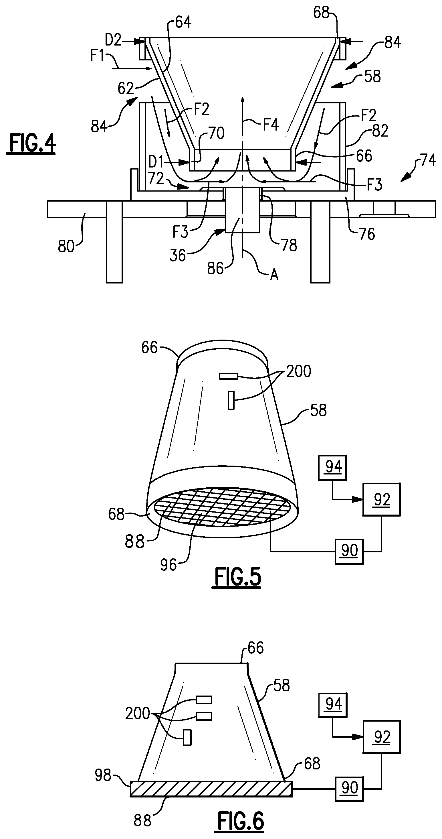
FIG. 4 shows one example of the flow passage 58 in greater detail. In this example, the flow passage 58 comprises a cone that has an outer surface 62 and an inner surface 64. The flow passage 58 has a base end 66 and extends to a distal end 68 that is defined by a diameter that is greater than a diameter of the base end 66. The base end 66 comprises a tubular section 70 of a generally constant diameter D1 and the distal end 68 is defined by a diameter D2 that is greater than D1. Optionally, a reverse configuration can have the inlet end with a larger diameter than the outlet end. The inner 64 and outer 62 surfaces of the flow passage 58 taper outwardly from the tubular section 70 to the distal end 68. In one example, the flow passage 58 is concentric with the doser axis A. In one example, the flow passage 58 may also having a continuously increasing taper from the base end 66 to the distal end 68.
The exhaust gas is directed to enter the base end 66 of the flow passage 58 in an evenly distributed manner about a gap 72 between the base end 66 and an inner surface of the mixer housing 40. A doser sub-assembly 74 is mounted to align with the doser axis A at the base end 66 of the flow passage 58. The doser sub-assembly 74 includes a plate 76 with an opening 78 that aligns with an opening in the mixer housing 40. A doser mount structure 80 abuts against the plate 76 and holds the doser 36. The doser sub-assembly 74 includes a cylindrical housing or sleeve 82 with one or more openings 84.
As shown in FIG. 4, the doser 36 includes a doser tip 86 that is configured to spray the reducing agent into the mixer 30 through the opening 78. The base end 66 of the flow passage 58 is positioned adjacent the opening 78 such that the gap 72 is formed within the doser sub-assembly 74 around the doser tip 86. Exhaust gas is directed to enter the base end 66 of the flow passage 58 through the annular gap 72 in a direction transverse to the doser axis A.
In one example, the sleeve 82 is fixed to the plate 76 and surrounds at least a portion of the flow passage 58. The openings 84 of the sleeve 82 direct exhaust gas in a first flow direction F1 against the outer surface 62 of the flow passage 58. The exhaust gas then flows in a second flow direction F2 along the outer surface 62 of the flow passage 58 toward the base end 66. The exhaust gas then flows in a third flow direction F3 to enter the annular gap 72 extending circumferentially around the base end 66. After flowing through the annular gap 72, the exhaust gas flows in a fourth flow direction F4 where it mixes with the reducing agent and to exits the flow passage 58 at the distal end 68. In one example, the fourth flow direction F4 extends generally along the doser axis A and is opposite of the second flow direction F2. Further, the third flow direction F3 is perpendicular to the fourth flow direction F4.
As shown in FIG. 3, the doser sub-assembly 74 is positioned between the inlet baffle 46 and outlet baffle 48 of the mixer 30. The openings 60 in the inlet baffle 46 and the openings 84 in the sleeve 82 facilitate an even distribution of the gas around the base of the flow passage 58 (FIG. 4) such that an evenly distributed flow enters the annular gap 72. In one example, the openings 84 are spaced circumferentially about the cylindrical body of the sleeve 82.
In another example shown in FIG. 7, a flow passage 58' comprises a cylindrical tube 100 that has an outer surface 102 and an inner surface 104. The flow passage 58' has a base end 106 and extends to a distal end 108 such that the tube 100 is defined by a constant diameter. In one example, the flow passage 58' is concentric with the doser axis A. The flow passage 58 is positioned within the mixing chamber 56 in manner similar to that described above with regard to the flow passage 58 that comprises a cone such that exhaust gas is evenly distributed around the base end 106 of the flow passage 58'.
In each of these examples, the flow passage 58, 58' comprises a solid structure or body that extends completely about the axis A. However, the flow passages 58, 58' may optionally include one or more slots 200 (FIGS. 5-7) for discrete amounts of exhaust gas to enter the flow passage to mix with the injected fluid and exhaust gas entering the inlet end of the flow passage 58, 58'. The slots 200 can have different shapes and/or sizes and can be positioned in any pattern to provide an optimum mixing configuration. In another example, instead of comprising a solid body, the flow passage 58, 58' can comprise a porous structure such as a metal mesh.
The doser 36 sprays the fluid into the flow passage 58 to mix with the exhaust gas entering via the gap 72. The fluid should be transformed as much as possible into ammonia (NH.sub.3) before exiting the mixer 30 and reaching the SCR catalyst 22. However, dosing at low temperatures has a tendency to create a deposits as there is insufficient heat to evaporate the fluid spray injected by the doser 36.
In order to address this problem, the subject invention provides at least one heating device 88 that is associated with the flow passage 58. The heating device 88 is connected to a power supply 90 and a control 92 selectively activates the heating device 88 when a temperature of the exhaust gas is below a predetermined temperature. The control 92 can be a dedicated electronic control unit, or can be part of the controller 38 for the injection system 32, or can be incorporated into another electronic control unit in the vehicle. One or more temperature sensors 94 can be used to measure exhaust gas temperature prior to entering the mixing chamber 56. The sensors 94 communicate data to the control 92. Typically, the control 92 activates the heating device 88 under cold start or low load conditions, for example. The heating device 88 heats the flow passage 58, 58' such that all fluid spray injected by the doser 36 evaporates prior to exiting the flow passage 58, 58' and entering the mixing chamber 56. In one example, an amount of energy required to heat the flow passage 58, 58' is determined based on an amount of injected fluid and the temperature of the exhaust gas.
In one example (FIG. 5), the heating device 88 is a heated plate 96 that heats a surface of the flow passage 58. The plate 96 is positioned within the flow passage 58 near the distal end 68, for example, such that the flow passage 58 completely surrounds the plate 96. The plate 96 can comprise a grid configuration or include multiple perforations/openings such that the ammonia/exhaust gas mixture can exit the flow passage 58 and enter the swirling flow pattern generated by the mixer 30. The swirling gas mixture then exits the mixer 30 via openings in the outlet baffle 48 and is directed toward the SCR catalyst 22.
In another example (FIG. 6), the heating device 88 is an electric coil 98 that heats a surface of the flow passage 58. The coil 98 is positioned at the outlet or distal end 68 of the flow passage 58. In one example, the coil 98 completely surrounds the outer surface 62 of the flow passage 58 at the distal end 68.
In another example (FIG. 7), the heating device 88 is positioned within an inner cavity 110 defined by the tube 100. The heating device 88 can be positioned at or near the distal end 108, for example. In this example, the heating 88 device comprises the heated plate 96, however, the device could also comprise a coil 98 positioned within or surrounding the tube 100.
In each example, the control 92 activates the plate 96 or coil 98 to heat the flow passage 58 to ensure that all fluid spray injected by the doser 36 evaporates prior to exiting the flow passage 58 and entering the mixing chamber 56. The plate 96 and coil 98 are examples of heating devices 88 that can be used to heat the flow passage 58; however, other types of heating devices could also be used.
As discussed above, the SCR device 22 is used to reduce NOx emissions by using ammonia (NH3) as the catalytic reductant. NH3 is injected as DEF fluid using the doser 36. The catalytic reduction is based on the ammonia decomposition and SCR activation; however, both of these have difficulty occurring at lower temperatures. The first step in ammonia decomposition is to evaporate the water in the DEF fluid, which is a process referred to as thermolysis, i.e. the breakdown of molecules by the action of heat. During the process of mixing, the DEF fluid takes this energy from the exhaust heat. At lower temperatures, the exhaust does not have enough energy, and the water does not evaporate completely which can result in significant deposit formation. This therefore limits the ability to dose at lower temperatures and the NOx produced by the exhaust system can pass to the tail pipe untreated.
The subject invention enables dosing of DEF fluid at lower temperatures by using the heating device 88 to heat surfaces in the mixer to help with the decomposition process when the exhaust gas energy itself is not sufficient to complete the process. The DEF spray impinges on the heated surfaces, which causes the water in the spray to evaporate before it can enter the mixing chamber thereby significantly reducing deposit formation. The amount of energy required to heat the surfaces is based on the amount of DEF injected and energy available in the exhaust. It is also essential that some exhaust gas flows through the heated surface along with the DEF at all times. This helps the heated surface from overheating.
Although an embodiment of this invention has been disclosed, a worker of ordinary skill in this art would recognize that certain modifications would come within the scope of this invention. For that reason, the following claims should be studied to determine the true scope and content of this invention.
* * * * *
D00000
D00001
D00002
D00003
D00004
XML
uspto.report is an independent third-party trademark research tool that is not affiliated, endorsed, or sponsored by the United States Patent and Trademark Office (USPTO) or any other governmental organization. The information provided by uspto.report is based on publicly available data at the time of writing and is intended for informational purposes only.
While we strive to provide accurate and up-to-date information, we do not guarantee the accuracy, completeness, reliability, or suitability of the information displayed on this site. The use of this site is at your own risk. Any reliance you place on such information is therefore strictly at your own risk.
All official trademark data, including owner information, should be verified by visiting the official USPTO website at www.uspto.gov. This site is not intended to replace professional legal advice and should not be used as a substitute for consulting with a legal professional who is knowledgeable about trademark law.