Vehicular camera system
Achenbach , et al. September 29, 2
U.S. patent number 10,787,125 [Application Number 15/457,056] was granted by the patent office on 2020-09-29 for vehicular camera system. This patent grant is currently assigned to MAGNA ELECTRONICS INC.. The grantee listed for this patent is MAGNA ELECTRONICS INC.. Invention is credited to Garret F. Achenbach, Christopher L. Van Dan Elzen, Brian J. Winden.


View All Diagrams
| United States Patent | 10,787,125 |
| Achenbach , et al. | September 29, 2020 |
Vehicular camera system
Abstract
A camera system for a vehicle includes a camera module having an imager assembly, a main circuit board and a camera housing, with the imager assembly including (i) an imager disposed on an imager circuit board and (ii) a lens assembly having a lens barrel accommodating a lens. A bracket is configured to attach at the vehicle windshield and to receive the camera module. The lens barrel extends from a portion of the lens assembly that is enclosed by the camera housing through an aperture to protrude outside the camera housing. With the camera module received by the bracket and with the bracket attached at the windshield, a forward portion of the camera housing is below the lens barrel. A separate stray light shield is disposed at the forward portion of the camera housing to reduce incidence of stray light at the lens.
| Inventors: | Achenbach; Garret F. (Rochester Hills, MI), Winden; Brian J. (Rochester, MI), Van Dan Elzen; Christopher L. (Rochester, MI) | ||||||||||
|---|---|---|---|---|---|---|---|---|---|---|---|
| Applicant: |
|
||||||||||
| Assignee: | MAGNA ELECTRONICS INC. (Auburn
Hills, MI) |
||||||||||
| Family ID: | 1000005081409 | ||||||||||
| Appl. No.: | 15/457,056 | ||||||||||
| Filed: | March 13, 2017 |
Prior Publication Data
| Document Identifier | Publication Date | |
|---|---|---|
| US 20170182944 A1 | Jun 29, 2017 | |
Related U.S. Patent Documents
| Application Number | Filing Date | Patent Number | Issue Date | ||
|---|---|---|---|---|---|
| 14233507 | 9596387 | ||||
| PCT/US2012/048993 | Jul 31, 2012 | ||||
| 61583431 | Jan 5, 2012 | ||||
| 61514191 | Aug 2, 2011 | ||||
| Current U.S. Class: | 1/1 |
| Current CPC Class: | H04N 5/2253 (20130101); B60R 1/04 (20130101); B60R 11/04 (20130101); H04N 5/2257 (20130101); H04N 5/2254 (20130101); B60R 1/00 (20130101); H04N 5/2251 (20130101); B60R 1/12 (20130101); H04N 5/2252 (20130101); B60R 2300/303 (20130101); B60K 2370/173 (20190501); B60R 2001/1253 (20130101); B60K 2370/777 (20190501); B60K 2370/21 (20190501); B60K 2370/152 (20190501); B60R 2300/102 (20130101); B60R 2011/0026 (20130101); B60R 2300/105 (20130101); B60R 2300/806 (20130101); B60R 2300/804 (20130101); B60R 2300/8026 (20130101); B60R 2001/1215 (20130101); Y10T 29/49169 (20150115); B60R 2300/607 (20130101) |
| Current International Class: | H04N 5/225 (20060101); H05K 7/20 (20060101); B60R 1/00 (20060101); B60R 1/04 (20060101); B60R 1/12 (20060101); B60R 11/04 (20060101); B60R 11/00 (20060101) |
References Cited [Referenced By]
U.S. Patent Documents
| 4514530 | April 1985 | Sellstrom et al. |
| 4634884 | January 1987 | Hayashimoto |
| 4712879 | December 1987 | Lynam et al. |
| 4786966 | November 1988 | Hanson et al. |
| 5073012 | December 1991 | Lynam |
| 5076673 | December 1991 | Lynam et al. |
| 5096287 | March 1992 | Kakinami et al. |
| 5098287 | March 1992 | Duncan et al. |
| 5115346 | May 1992 | Lynam |
| 5130804 | July 1992 | Tamura |
| 5140455 | August 1992 | Varaprasad et al. |
| 5142407 | August 1992 | Varaprasad et al. |
| 5151816 | September 1992 | Varaprasad et al. |
| 5204615 | April 1993 | Richards |
| 5253109 | October 1993 | O'Farrell et al. |
| 5371659 | December 1994 | Pastrick et al. |
| 5406414 | April 1995 | O'Farrell et al. |
| 5497306 | March 1996 | Pastrick |
| 5525264 | June 1996 | Cronin et al. |
| 5550677 | August 1996 | Schofield et al. |
| 5559556 | September 1996 | Kagebeck |
| 5567360 | October 1996 | Varaprasad et al. |
| 5610756 | March 1997 | Lynam et al. |
| 5657539 | August 1997 | Orikasa et al. |
| 5668663 | September 1997 | Varaprasad et al. |
| 5669699 | September 1997 | Pastrick et al. |
| 5670935 | September 1997 | Schofield et al. |
| 5724187 | March 1998 | Varaprasad et al. |
| 5760962 | June 1998 | Schofield et al. |
| 5796094 | August 1998 | Schofield et al. |
| 5821532 | October 1998 | Beaman et al. |
| 5823654 | October 1998 | Pastrick et al. |
| 5854708 | December 1998 | Komatsu et al. |
| 5872332 | February 1999 | Verma |
| 5877897 | March 1999 | Schofield et al. |
| 5910854 | June 1999 | Varaprasad et al. |
| 5920061 | July 1999 | Feng |
| 5949331 | September 1999 | Schofield et al. |
| 5978017 | November 1999 | Tino |
| 6002544 | December 1999 | Yatsu |
| 6013372 | January 2000 | Hayakawa et al. |
| 6071606 | June 2000 | Yamazaki et al. |
| 6072814 | June 2000 | Ryan et al. |
| 6087953 | July 2000 | DeLine et al. |
| 6097023 | August 2000 | Schofield et al. |
| 6117193 | September 2000 | Glenn |
| 6124886 | September 2000 | DeLine et al. |
| 6151065 | November 2000 | Steed |
| 6154306 | November 2000 | Varaprasad et al. |
| 6172613 | January 2001 | DeLine et al. |
| 6176602 | January 2001 | Pastrick et al. |
| 6178034 | January 2001 | Allemand et al. |
| 6193378 | February 2001 | Tonar et al. |
| 6201642 | March 2001 | Bos |
| 6222447 | April 2001 | Schofield et al. |
| 6243003 | June 2001 | DeLine et al. |
| 6250148 | June 2001 | Lynam |
| 6259475 | July 2001 | Ramachandran et al. |
| 6276821 | August 2001 | Pastrick et al. |
| 6278377 | August 2001 | DeLine et al. |
| 6292311 | September 2001 | Bohn et al. |
| 6302545 | October 2001 | Schofield et al. |
| 6313454 | November 2001 | Bos et al. |
| 6320176 | November 2001 | Schofield et al. |
| 6326613 | December 2001 | Heslin et al. |
| 6329925 | December 2001 | Skiver et al. |
| 6341523 | January 2002 | Lynam |
| 6353392 | March 2002 | Schofield et al. |
| 6396397 | May 2002 | Bos et al. |
| 6420975 | July 2002 | DeLine et al. |
| 6428172 | August 2002 | Hutzel et al. |
| 6445287 | September 2002 | Schofield et al. |
| 6454449 | September 2002 | Nestell et al. |
| 6466136 | October 2002 | DeLine |
| 6481003 | November 2002 | Maeda |
| 6483101 | November 2002 | Webster |
| 6498620 | December 2002 | Schofield et al. |
| 6501387 | December 2002 | Skiver et al. |
| 6523964 | February 2003 | Schofield et al. |
| 6535242 | March 2003 | Strumolo et al. |
| 6559435 | May 2003 | Schofield et al. |
| 6559439 | May 2003 | Tsuchida et al. |
| 6587152 | July 2003 | Sharp et al. |
| 6590658 | July 2003 | Case et al. |
| 6593565 | July 2003 | Heslin et al. |
| 6603612 | August 2003 | Nakano |
| 6611202 | August 2003 | Schofield et al. |
| 6651187 | November 2003 | Lacey, III |
| 6654187 | November 2003 | Ning |
| 6690268 | February 2004 | Schofield et al. |
| 6717610 | April 2004 | Bos et al. |
| 6757109 | June 2004 | Bos |
| 6768422 | July 2004 | Schofield et al. |
| 6774356 | August 2004 | Heslin |
| 6795237 | September 2004 | Marinelli |
| 6805767 | October 2004 | Shinomiya |
| 6806452 | October 2004 | Bos et al. |
| 6822563 | November 2004 | Bos et al. |
| 6824281 | November 2004 | Schofield et al. |
| 6831261 | December 2004 | Schofield et al. |
| 6891563 | May 2005 | Schofield et al. |
| 6897432 | May 2005 | Schmidtke et al. |
| 6946978 | September 2005 | Schofield |
| 6953253 | October 2005 | Schofield et al. |
| 6968736 | November 2005 | Lynam |
| 6977619 | December 2005 | March et al. |
| 7004593 | February 2006 | Weller et al. |
| 7004606 | February 2006 | Schofield |
| 7005974 | February 2006 | McMahon et al. |
| 7015944 | March 2006 | Holz et al. |
| 7031075 | April 2006 | Tsuji |
| 7038577 | May 2006 | Pawlicki et al. |
| 7095123 | August 2006 | Prior |
| 7095572 | August 2006 | Lee et al. |
| 7111996 | September 2006 | Seger |
| 7123168 | October 2006 | Schofield |
| 7188963 | March 2007 | Schofield et al. |
| 7205904 | April 2007 | Schofield |
| 7215479 | May 2007 | Bakin |
| 7255451 | August 2007 | McCabe et al. |
| 7262406 | August 2007 | Heslin et al. |
| 7265342 | September 2007 | Heslin et al. |
| 7268957 | September 2007 | Frenzel et al. |
| 7289037 | October 2007 | Uken et al. |
| 7311406 | December 2007 | Schofield et al. |
| 7325934 | February 2008 | Schofield et al. |
| 7339149 | March 2008 | Schofield et al. |
| 7344261 | March 2008 | Schofield et al. |
| 7355524 | April 2008 | Schofield |
| 7370983 | May 2008 | DeWind et al. |
| 7388182 | June 2008 | Schofield et al. |
| 7391458 | June 2008 | Sakamoto |
| 7402786 | July 2008 | Schofield et al. |
| 7419315 | September 2008 | Hirata et al. |
| 7420159 | September 2008 | Heslin et al. |
| 7423248 | September 2008 | Schofield et al. |
| 7423665 | September 2008 | Ray et al. |
| 7425076 | September 2008 | Schofield et al. |
| 7453509 | November 2008 | Losehand et al. |
| 7480149 | January 2009 | DeWard et al. |
| 7526103 | April 2009 | Schofield et al. |
| 7533998 | May 2009 | Schofield et al. |
| 7536316 | May 2009 | Ozer et al. |
| 7538316 | May 2009 | Heslin et al. |
| 7551103 | June 2009 | Schofield |
| 7579939 | August 2009 | Schofield et al. |
| 7599134 | October 2009 | Bechtel et al. |
| 7616781 | November 2009 | Schofield et al. |
| 7655894 | February 2010 | Schofield et al. |
| 7679498 | March 2010 | Pawlicki et al. |
| 7697027 | April 2010 | McMahon et al. |
| 7728721 | June 2010 | Schofield et al. |
| 7768574 | August 2010 | Humpston |
| 7877175 | January 2011 | Higgins-Luthman |
| 7888629 | February 2011 | Heslin et al. |
| 7889086 | February 2011 | Schafer et al. |
| 7916009 | March 2011 | Schofield et al. |
| 7918570 | April 2011 | Weller et al. |
| 7946505 | May 2011 | Lynam et al. |
| 7965336 | June 2011 | Bingle et al. |
| 7972045 | July 2011 | Schofield |
| 7994462 | August 2011 | Schofield et al. |
| 8063759 | November 2011 | Bos et al. |
| 8064146 | November 2011 | Iwasaki |
| 8070332 | December 2011 | Higgins-Luthman et al. |
| 8090153 | January 2012 | Schofield et al. |
| 8120652 | February 2012 | Bechtel et al. |
| 8142059 | March 2012 | Higgins-Luthman et al. |
| 8162518 | April 2012 | Schofield |
| 8179437 | May 2012 | Schofield et al. |
| 8192095 | June 2012 | Kortan et al. |
| 8194133 | June 2012 | DeWind et al. |
| 8203440 | June 2012 | Schofield et al. |
| 8222588 | July 2012 | Schofield et al. |
| 8223203 | July 2012 | Ohsumi et al. |
| 8239086 | August 2012 | Higgins-Luthman |
| 8254011 | August 2012 | Baur et al. |
| 8256821 | September 2012 | Lawlor et al. |
| 8289142 | October 2012 | Pawlicki et al. |
| 8294608 | October 2012 | Lynam |
| 8314689 | November 2012 | Schofield et al. |
| 8318512 | November 2012 | Shah et al. |
| 8324552 | December 2012 | Schofield et al. |
| 8325986 | December 2012 | Schofield et al. |
| 8339453 | December 2012 | Blake, III et al. |
| 8355839 | January 2013 | Schofield et al. |
| 8376595 | February 2013 | Higgins-Luthman |
| 8386114 | February 2013 | Higgins-Luthman |
| 8405725 | March 2013 | McMahon et al. |
| 8405726 | March 2013 | Schofield et al. |
| 8451332 | May 2013 | Rawlings |
| 8513590 | August 2013 | Heslin et al. |
| 8529075 | September 2013 | Yamada et al. |
| 8531278 | September 2013 | DeWard et al. |
| 8534887 | September 2013 | DeLine |
| 8542451 | September 2013 | Lu et al. |
| 8548315 | October 2013 | Okuda |
| 8629768 | January 2014 | Bos et al. |
| 8665079 | March 2014 | Pawlicki et al. |
| 8743203 | June 2014 | Karner |
| 8763970 | July 2014 | Mordau et al. |
| 8851690 | October 2014 | Uken |
| 8944655 | February 2015 | Verrat-Debailleul |
| 9150165 | October 2015 | Fortin |
| 9156403 | October 2015 | Rawlings |
| 9193308 | November 2015 | Okuda |
| 9266474 | February 2016 | DeWard et al. |
| 9277104 | March 2016 | Sesti et al. |
| 9338334 | May 2016 | Lu et al. |
| 9380219 | June 2016 | Salomonsson et al. |
| 9451138 | September 2016 | Winden et al. |
| 9487159 | November 2016 | Achenbach |
| 9497368 | November 2016 | Winden et al. |
| 9596387 | March 2017 | Achenbach et al. |
| 9630570 | April 2017 | Salomonsson et al. |
| 9635230 | April 2017 | Winden et al. |
| 9871971 | January 2018 | Wang et al. |
| 9878679 | January 2018 | Salomonsson et al. |
| 9883088 | January 2018 | Winden et al. |
| 10033934 | July 2018 | Wang et al. |
| 10046716 | August 2018 | Okuda et al. |
| 10065575 | September 2018 | Salomonsson et al. |
| 10264168 | April 2019 | Winden et al. |
| 10277825 | April 2019 | Wang et al. |
| 2002/0003571 | January 2002 | Schofield |
| 2002/0156559 | October 2002 | Stam et al. |
| 2002/0159270 | October 2002 | Lynam et al. |
| 2003/0090569 | May 2003 | Poechmueller |
| 2003/0137595 | July 2003 | Takachi |
| 2003/0169522 | September 2003 | Schofield et al. |
| 2004/0016870 | January 2004 | Pawlicki et al. |
| 2004/0032321 | February 2004 | McMahon et al. |
| 2004/0051634 | March 2004 | Schofield et al. |
| 2004/0189862 | September 2004 | Gustavsson et al. |
| 2005/0083590 | April 2005 | Tanigawa et al. |
| 2005/0104995 | May 2005 | Spryshak et al. |
| 2005/0141106 | June 2005 | Lee et al. |
| 2005/0184352 | August 2005 | Jeong et al. |
| 2005/0190283 | September 2005 | Ish-Shalom et al. |
| 2005/0232469 | October 2005 | Schofield et al. |
| 2005/0274883 | December 2005 | Nagano |
| 2006/0038668 | February 2006 | DeWard et al. |
| 2006/0049533 | March 2006 | Kamoshita |
| 2006/0050018 | March 2006 | Hutzel et al. |
| 2006/0054802 | March 2006 | Johnston |
| 2006/0056077 | March 2006 | Johnston |
| 2006/0061008 | March 2006 | Karner |
| 2006/0065436 | March 2006 | Gally et al. |
| 2006/0077575 | April 2006 | Nakai et al. |
| 2006/0103727 | May 2006 | Tseng |
| 2006/0125919 | June 2006 | Camilleri et al. |
| 2006/0171704 | August 2006 | Bingle et al. |
| 2006/0184297 | August 2006 | Higgins-Luthman |
| 2006/0202038 | September 2006 | Wang et al. |
| 2007/0096020 | May 2007 | Mitsugi et al. |
| 2007/0109406 | May 2007 | Schofield et al. |
| 2007/0120657 | May 2007 | Schofield et al. |
| 2007/0221826 | September 2007 | Bechtel |
| 2007/0279518 | December 2007 | Apel et al. |
| 2008/0024833 | January 2008 | Kawasaki |
| 2008/0024883 | January 2008 | Iwasaki |
| 2008/0043105 | February 2008 | Kallhammer et al. |
| 2008/0121034 | May 2008 | Lynam |
| 2008/0247751 | October 2008 | Lang et al. |
| 2008/0252882 | October 2008 | Kesterson |
| 2009/0010494 | January 2009 | Bechtel et al. |
| 2009/0046150 | February 2009 | Hayakawa et al. |
| 2009/0085755 | April 2009 | Schafer |
| 2009/0208058 | August 2009 | Schofield et al. |
| 2009/0244361 | October 2009 | Gebauer et al. |
| 2009/0295181 | December 2009 | Lawlor |
| 2010/0103308 | April 2010 | Butterfield et al. |
| 2010/0110192 | May 2010 | Johnston et al. |
| 2010/0118146 | May 2010 | Schofield et al. |
| 2010/0134616 | June 2010 | Seger et al. |
| 2010/0165468 | July 2010 | Yamada et al. |
| 2010/0279438 | November 2010 | An et al. |
| 2010/0279439 | November 2010 | Shah et al. |
| 2010/0283581 | November 2010 | Heigl |
| 2011/0025850 | February 2011 | Maekawa et al. |
| 2011/0035120 | February 2011 | Taylor et al. |
| 2011/0163904 | July 2011 | Alland |
| 2011/0233248 | September 2011 | Flemming et al. |
| 2011/0298968 | December 2011 | Tseng et al. |
| 2012/0008129 | January 2012 | Lu et al. |
| 2012/0013741 | January 2012 | Blake |
| 2012/0069185 | March 2012 | Stein |
| 2012/0075471 | March 2012 | Seger et al. |
| 2012/0081550 | April 2012 | Sewell |
| 2012/0182425 | July 2012 | Higgins-Luthman et al. |
| 2012/0207461 | August 2012 | Okuda |
| 2012/0265416 | October 2012 | Lu |
| 2013/0002873 | January 2013 | Hess |
| 2013/0044021 | February 2013 | Lynam |
| 2014/0000804 | January 2014 | Looi et al. |
| 2014/0015977 | January 2014 | Taylor |
| 2014/0016919 | January 2014 | Okuda |
| 2014/0022657 | January 2014 | Lu et al. |
| 2014/0043465 | February 2014 | Salomonsson |
| 2014/0160284 | June 2014 | Achenbach et al. |
| 2014/0226012 | August 2014 | Achenbach et al. |
| 2015/0015713 | January 2015 | Wang |
| 2015/0042798 | February 2015 | Takeda et al. |
| 2015/0251605 | September 2015 | Uken et al. |
| 2017/0187931 | June 2017 | Onishi et al. |
| 01059596 | Mar 1992 | CN | |||
| 1743887 | Mar 2006 | CN | |||
| 101681530 | Mar 2010 | CN | |||
| 101799614 | Aug 2010 | CN | |||
| 102008044003 | May 2010 | DE | |||
| 102010023593 | Dec 2011 | DE | |||
| 102010023593 | Dec 2011 | DE | |||
| 0889801 | Jan 1999 | EP | |||
| 1271214 | Jan 2003 | EP | |||
| 1351316 | Oct 2003 | EP | |||
| 1605520 | Dec 2005 | EP | |||
| 1025702 | Nov 2006 | EP | |||
| 1504276 | Aug 2012 | EP | |||
| 08084277 | Mar 1996 | JP | |||
| 2006-293100 | Oct 2006 | JP | |||
| 2006-350372 | Dec 2006 | JP | |||
| 2007243550 | Sep 2007 | JP | |||
| 2010042703 | Feb 2010 | JP | |||
| 2001/044850 | Jun 2001 | WO | |||
| 2004/010679 | Jan 2004 | WO | |||
| 2006/029995 | Mar 2006 | WO | |||
| 2006/029996 | Mar 2006 | WO | |||
| 2007/053404 | May 2007 | WO | |||
| WO2008024639 | Feb 2008 | WO | |||
| WO2008127752 | Oct 2008 | WO | |||
| WO2009046268 | Apr 2009 | WO | |||
| WO2010/111465 | Sep 2010 | WO | |||
| 2011/111465 | Sep 2011 | WO | |||
| WO2013/019795 | Feb 2013 | WO | |||
| WO2013/081984 | Jun 2013 | WO | |||
| WO2013/081985 | Jun 2013 | WO | |||
| WO2013/123161 | Aug 2013 | WO | |||
Other References
|
International Search Report and Written Opinion dated Oct. 22, 2012 from corresponding PCT Application No. PCT/US2012/048993. cited by applicant. |
Primary Examiner: Atala; Jamie J
Assistant Examiner: Demosky; Patrick E
Attorney, Agent or Firm: Honigman LLP
Parent Case Text
CROSS REFERENCE TO RELATED APPLICATIONS
The present application is a continuation of U.S. patent application Ser. No. 14/233,507, filed Jul. 31, 2012, now U.S. Pat. No. 9,596,387, which is a 371 U.S. national phase application of PCT Application No. PCT/US2012/048993, filed Jul. 31, 2012, which claims the filing benefits of U.S. provisional application Ser. No. 61/583,431, filed Jan. 5, 2012, and Ser. No. 61/514,191, filed Aug. 2, 2011, which are hereby incorporated herein by reference in their entireties.
Claims
What is claimed is:
1. A camera system for a vehicle, said camera system comprising: a camera module comprising an imager assembly, a main circuit board and a camera housing; wherein said imager assembly comprises (i) an imager disposed on an imager circuit board and (ii) a lens assembly comprising a lens barrel accommodating a lens; a bracket configured to attach at a windshield of a vehicle equipped with said camera system; wherein said bracket is configured to receive said camera module so that, with said camera module received by said bracket and with said bracket attached at the windshield, said camera module is mounted at the windshield with said lens viewing through the windshield in a forward direction of travel of the equipped vehicle; wherein said main circuit board is operatively connected to said imager circuit board, said main circuit board including at least one processor for processing image data captured by said imager; wherein said camera housing houses and encloses said main circuit board, said imager circuit board and a portion of said lens assembly; wherein said camera housing has an aperture; wherein said lens barrel extends from the portion of said lens assembly enclosed by said camera housing through said aperture to protrude outside said camera housing; wherein said camera housing comprises a forward portion in front of where said imager assembly is disposed in said camera housing; wherein said main circuit board is disposed at least within said forward portion; wherein, with said camera module received by said bracket and with said bracket attached at the windshield, said forward portion of said camera housing is below said lens barrel; and a separate stray light shield formed separate from said camera housing, wherein said stray light shield is attached at said forward portion of said camera housing to reduce incidence of stray light at said lens.
2. The camera system of claim 1, wherein said lens assembly is protected against contaminant incursion.
3. The camera system of claim 2, wherein a gasket is disposed at said bracket, and wherein, with said camera module received by said bracket and with said bracket attached at the windshield, said gasket protects said lens from contaminants.
4. The camera system of claim 1, wherein said stray light shield comprises ridges that, with said camera module received by said bracket and with said bracket attached at the windshield, reduce incidence of stray light at said lens.
5. The camera system of claim 1, wherein said stray light shield is detachably attached at said forward portion of said camera housing.
6. The camera system of claim 1, wherein said bracket is configured to attach at attaching elements that are adhesively attached at an in-cabin surface of the windshield.
7. The camera system of claim 1, wherein said imager circuit board extends at least partially through an opening of said main circuit board.
8. The camera system of claim 1, wherein said lens barrel is tilted at an angle with respect to said main circuit board.
9. A camera system for a vehicle, said camera system comprising: a camera module comprising an imager assembly, a main circuit board and a camera housing; wherein said imager assembly comprises (i) an imager disposed on an imager circuit board and (ii) a lens assembly comprising a lens barrel accommodating a lens; a bracket configured to attach at a windshield of a vehicle equipped with said camera system; wherein said bracket is configured to receive said camera module so that, with said camera module received by said bracket and with said bracket attached at the windshield, said camera module is mounted at the windshield with said lens viewing through the windshield in a forward direction of travel of the equipped vehicle; wherein said main circuit board is operatively connected to said imager circuit board, said main circuit board including at least one processor for processing image data captured by said imager; wherein said camera housing houses and encloses said main circuit board, said imager circuit board and a portion of said lens assembly; wherein said camera housing has an aperture; wherein said lens barrel extends from the portion of said lens assembly enclosed by said camera housing through said aperture to protrude outside said camera housing; wherein said camera housing comprises a forward portion in front of where said imager assembly is disposed in said camera housing; wherein said main circuit board is disposed at least within said forward portion; wherein, with said camera module received by said bracket and with said bracket attached at the windshield, said forward portion of said camera housing is below said lens barrel; a separate stray light shield formed separate from said camera housing, wherein said stray light shield is attached at said forward portion of said camera housing to reduce stray light reflected to said lens; wherein said stray light shield is detachably attached at said forward portion of said camera housing; and wherein said stray light shield comprises ridges that, with said camera module received by said bracket and with said bracket attached at the windshield and with said stray light shield attached at said forward portion of said camera housing, reduce incidence of stray light at said lens.
10. The camera system of claim 9, wherein said stray light shield snap attaches at said forward portion of said camera housing.
11. The camera system of claim 10, wherein said stray light shield snap attaches via a mechanical clip and notch connection at each side of said camera housing.
12. The camera system of claim 9, wherein said lens assembly is protected against contaminant incursion.
13. The camera system of claim 12, wherein a gasket is disposed at said bracket, and wherein, with said camera module received by said bracket and with said bracket attached at the windshield, said gasket protects said lens from contaminants.
14. The camera system of claim 9, wherein said bracket is configured to attach at attaching elements that are adhesively attached at an in-cabin surface of the windshield.
15. The camera system of claim 9, wherein said imager circuit board extends at least partially through an opening of said main circuit board.
16. The camera system of claim 9, wherein said lens barrel is tilted at an angle with respect to said main circuit board.
17. A camera system for a vehicle, said camera system comprising: a camera module comprising an imager assembly, a main circuit board and a camera housing; wherein said imager assembly comprises (i) an imager disposed on an imager circuit board and (ii) a lens assembly comprising a lens barrel accommodating a lens; a bracket configured to attach at a windshield of a vehicle equipped with said camera system; wherein said bracket is configured to receive said camera module so that, with said camera module received by said bracket and with said bracket attached at the windshield, said camera module is mounted at the windshield with said lens viewing through the windshield in a forward direction of travel of the equipped vehicle; wherein said main circuit board is operatively connected to said imager circuit board, said main circuit board including at least one processor for processing image data captured by said imager; wherein said lens barrel is tilted at an angle with respect to said main circuit board; wherein said camera housing houses and encloses said main circuit board, said imager circuit board and a portion of said lens assembly; wherein said camera housing has an aperture; wherein said lens barrel extends from the portion of said lens assembly enclosed by said camera housing through said aperture to protrude outside said camera housing; wherein said camera housing comprises a forward portion in front of where said imager assembly is disposed in said camera housing; wherein said main circuit board is disposed at least within said forward portion; wherein said imager circuit board is not accommodated in said forward portion of said camera housing; wherein, with said camera module received by said bracket and with said bracket attached at the windshield, said forward portion of said camera housing is below said lens barrel; and a separate stray light shield formed separate from said camera housing, wherein said stray light shield is attached at said forward portion of said camera housing to reduce incidence of stray light at said lens.
18. The camera system of claim 17, wherein said lens assembly is protected against contaminant incursion.
19. The camera system of claim 18, wherein a gasket is disposed at said bracket, and wherein, with said camera module received by said bracket and with said bracket attached at the windshield, said gasket protects said lens from contaminants.
20. The camera system of claim 17, wherein said stray light shield comprises ridges that, with said camera module received by said bracket and with said bracket attached at the windshield, reduce incidence of stray light at said lens.
21. The camera system of claim 17, wherein said stray light shield is detachably attached at said forward portion of said camera housing.
22. The camera system of claim 17, wherein said bracket is configured to attach at attaching elements that are adhesively attached at an in-cabin surface of the windshield.
23. The camera system of claim 17, wherein said imager circuit board extends at least partially through an opening of said main circuit board.
Description
FIELD OF THE INVENTION
This disclosure relates to vehicles, and more particularly, to a vehicular camera system.
BACKGROUND OF THE INVENTION
Vehicular camera systems can provide vehicle operators with valuable information about driving conditions. For example, a typical vehicle camera system can aid a driver in parking her automobile by alerting her to hazards around her automobile that should be avoided. Other uses for vehicle camera system are also known.
However, front-facing vehicular camera systems may obstruct a driver's field of view and may require space within the vehicle beyond what can readily be provided.
SUMMARY OF THE INVENTION
According to one aspect of this disclosure, a vehicular camera system includes a circuit board that has an opening therein. An imager assembly of the vehicular camera system can include a portion, such as a flexible portion, that extends through the opening in the circuit board.
BRIEF DESCRIPTION OF THE DRAWINGS
The drawings illustrate, by way of example only, embodiments of the present disclosure.
FIG. 1 is a perspective view of a vehicular camera system;
FIG. 2 is a perspective view of a vehicle having the vehicular camera system;
FIG. 3 is a plan view of a main circuit board of the vehicular camera system;
FIG. 4A is a hidden-line top view of the vehicular camera system showing internal components;
FIG. 4B is a hidden-line perspective view of the vehicular camera system showing internal components;
FIG. 4C is a section view of the vehicular camera system along section line C-C of FIG. 4A;
FIG. 5A is an exploded view of the vehicular camera system;
FIG. 5B is an exploded view of the imager assembly;
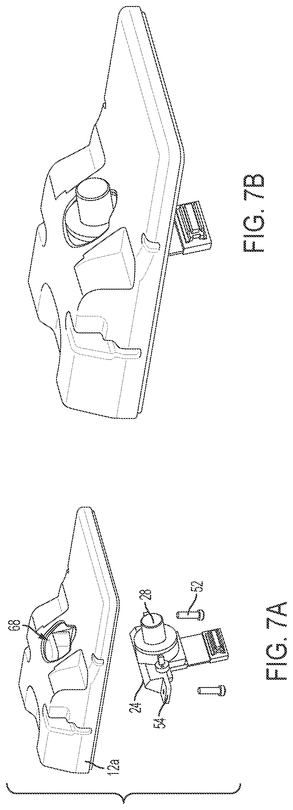
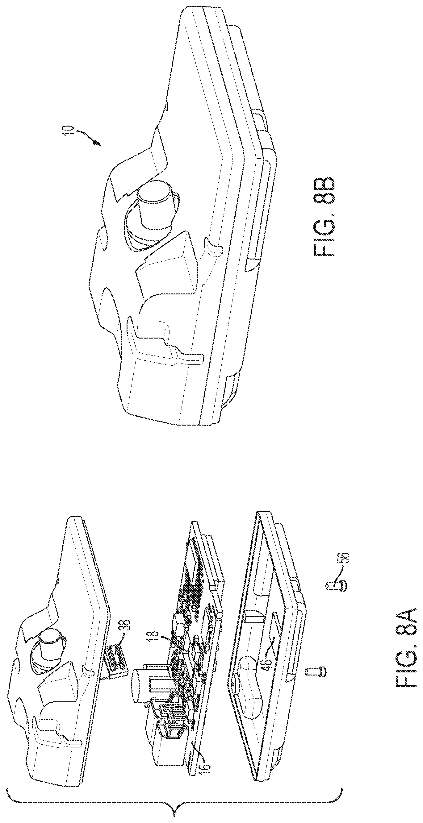
FIGS. 6A-B, 7A-B, 8A-B are perspective views that show a method of assembly of the vehicular camera system;
FIG. 9 is a perspective view of a vehicular camera system with a stray light shield;
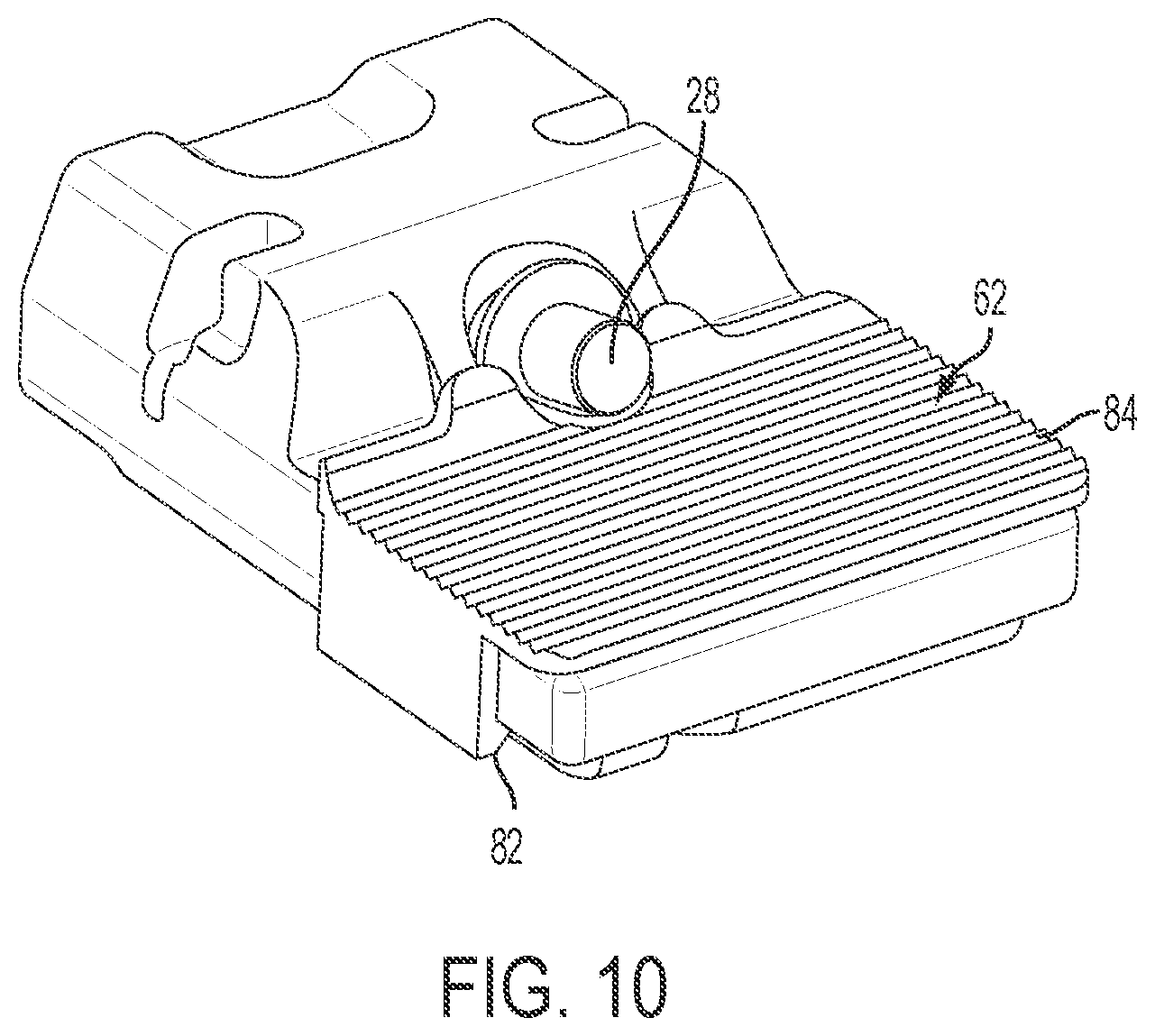
FIG. 10 is a perspective view of a vehicular camera system with another stray light shield;
FIG. 11 is a perspective view of another vehicular camera system of the present invention;
FIGS. 12A and 12B are sectional views taken along the line XII-XII in FIG. 11, showing the camera system mounted at windshields having different windshield angles; and
FIG. 13 is a side elevation and partial sectional view of the vehicular camera system of FIG. 11.
DETAILED DESCRIPTION OF THE INVENTION
A vehicular camera system can be installed on the inside of the front windshield of a vehicle, such as a car, truck, bus, or van. Such a camera system may be used for a variety of functions such as object detection, lane keeping, and high beam control. FIG. 1 shows an example of a vehicular camera system or module 10 configured to be attached in a front-facing manner to a vehicle. The camera system 10 includes a housing 12 and a lens barrel 14 projecting therefrom.
FIG. 2 shows a forward-facing position for a camera system 10 in the vehicle 100. The camera system or module 10 can be attached to the windshield 102, as shown, such as via a frame or bracket that is adhesively attached at the windshield via a plurality of fixing elements or attachment elements. Other positions are also possible. The camera system or camera module of the present invention may utilize aspects of the systems and/or modules described in U.S. Pat. Nos. 7,916,009; 7,888,629; 7,728,721; 7,533,998; 7,536,316; 7,480,149; 7,420,159; 7,289,037; 7,265,342; 7,262,406; 7,004,593; 6,824,281 and/or 6,690,268, and/or U.S. patent application Ser. No. 11/721,406, filed Jun. 11, 2007 and published Dec. 3, 2009 as U.S. Publication No. US-2009-0295181, which are all hereby incorporated herein by reference in their entireties.
Since the camera system 10 uses a portion of the limited amount of space on the windshield 102, which is needed for a clear view of the road and/or placement of other components of the vehicle, the camera housing 12 can be made as small as practical. A height H (see FIG. 4C) of the camera housing 12 tends to have a relatively significant effect on driver and passenger visual perception. As will be discussed below, the components of the camera system 10 can be configured to reduce the height H. In one example, the height H can be reduced to about 28 mm (about 1.1 inches), which is about 15 percent smaller than a comparable camera system.
As shown in FIG. 3, the camera system 10 includes a main circuit board 16, such as a printed circuit board (PCB), that has an opening 18, which may be referred to as a hole or a cut-out section. The opening 18 can be approximately centrally located, as depicted, in the main PCB 16, or, in other examples, can be positioned at other locations. The opening 18 is surrounded by material of the main PCB 16. The opening 18 can be formed by any mechanical technique suitable for the material of the main PCB 16, such as cutting, punching, drilling, or milling, or by another technique, such as laser cutting. The opening 18 can be formed during the fabrication process of PCB material for use as PCBs or can be formed subsequently. In the embodiment shown in FIG. 3, the opening 18 has a rectangular shape with rounded inside corners. In other embodiments other shapes, such as elliptical, can be used for the opening 18.
As seen in FIGS. 4A-C, the main PCB 16 is installed extending along a breadth B and length L of the housing 12. The main PCB 16 is dual-sided and has circuitry or electrical components or elements established at or populated at both sides of the PCB. The main PCB 16 supports or includes or carries or has established thereon a digital image processor 20, memory components, power supply components, and a vehicle connector 22, which are electrically operatively coupled together by conductive traces and vias. The processor 20 and memory are cooperatively configured to provide functions such as image processing, object detection, and lane detection. The main PCB 16 can be multilayered.
In the above-mentioned example where the height H of the camera housing 12 is about 28 mm (about 1.1 inches), the breadth B of the housing 12 can be about 58 mm (about 2.3 inches) and the length can be about 85 mm (about 3.3 inches). A forward height H2 of the housing can be about 10 mm (about 0.4 inches). In addition to the 15 percent reduction in height, these dimensions afford as much as a 35 percent reduction in breadth and a 15 percent reduction in length with respect to the comparable camera system.
An imager assembly 24 extends through the opening 18 of the main PCB 16. The imager assembly 24 includes an imager 26, such as an integrated circuit (IC) imager, which receives light directed by a lens 28 positioned in front of the imager 26 to capture a scene in front of the vehicle. The imager 26 can include a charge-coupled device (CCD), a complementary metal-oxide semiconductor (CMOS) active-pixel sensor (APS), or similar device. The imager 26 is connected to an imager circuit board 30 (such as a PCB), and a lens holder 32 mechanically fixes the lens 28 to the imager PCB 30. The imager PCB 30 and the lens holder 32 extend along the height H of the housing 12 partially through the opening 18 of the main PCB 16, which can allow for the above-mentioned reduction in the height H of the housing 12. The imager PCB 30 extending along the height H need not be parallel to the height H, and the imager PCB 30 can be tilted at an angle, as depicted, resulting in the other components of the imager assembly 24 being tilted as well. The magnitude of such angle can be selected to allow for the height H of the housing 12 to meet an operational constraint. For example, when a taller housing 12 is acceptable, then the angle can be 90 degrees, meaning that the imager PCB 30 extends parallel to the height H or perpendicular to the main PCB 16. When a shorter housing 12 is needed, the magnitude of the angle can be reduced, thereby tilting the imager PCB 30 with respect to the main PCB 16 so that the imager PCB 30 is not perpendicular to the main PCB 16 (as depicted). The location in the vehicle of the camera system 10 can be taken into account when determining the angle of the imager PCB 30. Geometric factors such as windshield slope and shape of the housing 12 as well as the desired field of view of the camera system 10 can be taken into account. In this example, the angle is about 75 degrees. In other examples, the angle can be smaller, such as 60 degrees, or larger.
The imager PCB 30 also includes a flexible portion 34 that terminates at a small rigid PCB terminator 36. The flexible portion 34 can include any of a flexible connector (also known as a flex connector), a flexible PCB, a ribbon cable, wires, or the like. The flexible portion 34 includes conductors that electrically connect the components of the imager PCB 30 to the terminator 36. The terminator 36 has an electrical connector 38 that attaches to a mating electrical connector 40 on the underside 64 of the main PCB 16. The flexible connector or ribbon cable provides image signals/data (such as LVDS signals or the like) to the circuitry of the main PCB. Thus, the imager 26 and the main PCB 16 are operatively connected to allow image signals/data captured by the imager 26 to be received at the processor 20. The underside 64 is located opposite a top side 66 of the main PCB 16 on which the lens 28 is positioned. The electrical connector 38 can be removably attachable to the electrical connector 40.
FIG. 5A shows an exploded view of the camera system 10, where it will be seen that the housing 12 can be subdivided into an upper cover 12a and a lower cover 12b. FIG. 5B shows an exploded view of the imager assembly 24. The housing upper cover 12a includes a lens opening 68 through which the lens 28 of the imager assembly 24 receives light.
Protective components can be installed within the housing 12 and can include a lens gasket 42, an imager resilient member 44, a heat sink 46, and a connector resilient member 48. The lens gasket 42 serves to reduce or eliminate infiltration of dust, particulate or moisture into the imager assembly 24 between the lens 28 and the lens holder 32. The heat sink 46 is positioned on the processor 20 to collect and dissipate heat generated by the processor 20. Each of the resilient members 44, 48 can include a foam cushion, or the like. The imager resilient member 44 is of rectangular shape with a central rectangular opening sized to accommodate the imager 26. The imager resilient member 44 surrounds the imager 26 and is sandwiched between the imager PCB 30 and the lens holder 32, and serves to reduce or eliminate infiltration of dust, particulate, or moisture past the imager PCB 30 and the lens holder 32 to protect the imager 26.
As shown in FIG. 4C, the connector resilient member 48 is sandwiched between the PCB terminator 36 that carries the electrical connector 38 and the lower cover 12b of the housing 12, and accordingly, the connector resilient member 48 transmits force from the lower cover 12b to the electrical connector 38 to ensure that the electrical connector 38 is firmly seated to the mating electrical connector 40 of the main PCB 16 in order to maintain a sound electrical connection between the imager PCB 30 and the main PCB 16. In this example, the thickness of the connector resilient member 48 is selected to be larger than the space between the lower cover 12b of the housing and the terminator 36, so that the resiliency of the connector resilient member 48 provides an effective seating force.
FIGS. 6A-B, 7A-B and 8A-B show a method of assembling the camera system 10.
First, as shown in FIGS. 6A and 6B, the imager assembly 24 is assembled. The lens 28 is screwed into the lens holder 32, or alternatively another technique, such as adhesive bonding, is used to mount the lens 28 to the lens holder 32. The lens holder 32 is fixed to the imager PCB 30 using, for example, one or more fasteners 50 (e.g., screws) that extend through holes 70 in the imager PCB 30 and mate with threaded holes in the lens holder 32. The lens gasket 42 is slid over and around the lens 28.
Next, as shown in FIGS. 7A and 7B, the imager assembly 24 is placed in the housing upper cover 12a such that the lens 28 is aligned with the lens opening 68. The imager assembly 24 is mounted to the inside of the housing upper cover 12a by, for example, one or more fasteners 52 (such as, for example, screws or the like), which can mate with corresponding features (such as, for example, threaded holes or the like) in the upper cover 12a. The lens holder 32 (see also FIG. 4B) includes wings 54 on either side having openings for receiving the fasteners 52.
Next, the main PCB 16 is brought into alignment with the housing upper cover 12a and is fitted so that a portion of the imager assembly 24 extends through the opening 18 of the main PCB 16, as seen best in FIG. 4C. The connector resilient member 48 is positioned on the inside of the housing lower cover 12b, and can be held in place using an adhesive or other technique. The connector 38 is then extended through the opening 18 in the main PCB 16 (as can be seen in FIG. 8A), aligned with the mating connector 40 on the underside 64 of the main PCB 16 by virtue of the flexible portion 34, and mated with the connector 40. The electrical connection between the imager PCB 30 and the main PCB 16 is made. The housing lower cover 12b is then fastened to the housing upper cover 12a via, for example, one or more fasteners 56, which compresses the connector resilient member 48 to firmly seat the camera-side connector 38 on the mating main PCB-side connector 40.
In other examples, the method steps described above can be performed in an order different from that described.
FIG. 9 shows a frame or bracket 60 that can be attached to the camera housing 12 and that provides a stray light shield or light baffle or the like. The stray light shield can function to reduce capture by the camera lens 28 of stray light or glare that may, for example, be reflected off of the windshield. The frame or bracket 60 can be attached to the housing 12 by, for example, a mechanical clip-and-notch structure, referenced at 72, whereby the housing 12 of the accessory or camera module 10 may modularly locate and/or attach at the frame or bracket 60 with the frame or bracket attached at the windshield via fixing elements or attachment elements 76. Narrowing slots 74 can be provided in the frame or bracket to removably mate with knobs or structure on the backs of the fixing elements 76. The pads of fixing elements 76 can be attached to the vehicle windshield by way of an adhesive (and such as by utilizing aspects of the modules described in U.S. patent application Ser. No. 11/721,406, filed Jun. 11, 2007 and published Dec. 3, 2009 as U.S. Publication No. US-2009-0295181, which is hereby incorporated herein by reference in its entirety). Alternatively, the pads can be suction pads. The stray light shield of the frame or bracket 60 may comprise ridges 78 positioned (such as below and in front of the lens) to reduce the amount of light reflected into the lens 28 (such as by utilizing aspects of the vision systems described in U.S. provisional application Ser. No. 61/600,205, filed Feb. 17, 2012, which is hereby incorporated herein by reference in its entirety). Further, a shield gasket 80 can be positioned on the frame or bracket 60 around the lens 28 to reduce incursion of dust, particulate, or moisture into the vicinity of the lens 28. The gasket may utilize aspects of the gaskets described in U.S. patent application Ser. No. 12/393,223, filed Feb. 26, 2009, abandoned, which is hereby incorporated herein by reference in its entirety.
FIG. 10 shows another stray light shield 62 that can be attached to or established at the camera housing 12. The stray light shield 62 can function to reduce capture by the camera lens 28 of stray light or glare that may, for example, be reflected off of the windshield. The stray light shield 62 can be attached to the housing 12 by, for example, a mechanical clip-and-notch structure, at 82, and the module (with the stray light shield at the housing) may be mechanically attached to a frame or bracket adhesively attached at the windshield via a plurality of spaced apart fixing elements or attaching elements or the like. The stray light shield 62 can include ridges 84 positioned to reduce the amount of light reflected into the lens 28. The stray light shield may comprise any suitable material, such as a shield that utilizes aspects of the light baffling system of the vision systems described in U.S. provisional application Ser. No. 61/600,205, filed Feb. 17, 2012, which is hereby incorporated herein by reference in its entirety.
Optionally, and with reference to FIGS. 11-13, a camera module 110 may be adjustable to adapt or configure the module for different windshield applications (having different angles relative to horizontal) of different vehicles, while still providing the desired, generally horizontal, forward field of view of the camera or imager assembly 124. The camera module 110 is configured to mechanically attach to a frame or bracket 160, which includes a plurality of fixing elements or attaching elements 176, which are configured for adhesive attachment to the in-cabin surface of the vehicle windshield. The camera module 110 may attach to the frame or bracket (with the frame or bracket attached at the windshield surface) via any suitable means, such as via a sliding engagement or snap attachment or the like.
As can be seen with reference to FIGS. 12A and 12B, the imager assembly 124 (including the imager 126, lens 128, imager circuit element or board 130 and lens holder 132) extends through the opening 118 of the main circuit element or board 116 and may be adjusted or pivoted relative to the camera module housing 112 and main circuit board 116 to adjust the angle of the imager assembly (and the imager 126 and lens 128) relative to horizontal so as to provide the desired field of view and viewing angle or lens tip angle of the imager assembly for different windshield/vehicle applications. For example, and as shown in FIG. 12A, for a windshield with a reduced slope, the imager assembly 124 is pivoted or adjusted or set to provide the desired or appropriate lens tip angle when the camera module 110 is attached at the frame or bracket 160 at the windshield 102. For a windshield with a greater slope, and such as shown in FIG. 12B, the imager assembly 124 is pivoted or adjusted or set at a different angle relative to the main circuit board 116 to provide the desired or appropriate lens tip angle when the camera module 110 is attached at the frame or bracket 160 at the windshield. In both configurations shown in FIGS. 12A and 12B, the distance D from the inner surface of the windshield 102 to the lower surface of the housing 112 (when the camera module 110 is attached at the frame or bracket 160 at the windshield) is about the same because the camera modules mount or attach at the windshield in the same manner, with only the imager assembly being adjusted or pivoted within the module to adjust the viewing angle or lens tip angle of the imager assembly.
The imager assembly 124 is mounted at the housing 112 (or to the main circuit board 116 or the like) via one or more threaded fasteners. For example, and as shown in FIG. 13, the imager assembly 124 may include a holder or mounting structure 125 (such as a plastic holder or the like) that is attached at the housing 112 and supports the imager 126 and lens assembly 128 and imager circuit board 130). The holder 125 includes a mounting or stationary or fixed portion 125a that may be attached or fastened to a threaded fastener 112a of the housing, whereby a rotatable portion or adjustable portion 125b of holder 125 of imager assembly 124 may be rotatable or pivotable or adjustable relative to the mounting portion 125a to provide for adjustment of the tip angle of the lens 128 and viewing angle of the imager 126 relative to the housing 112 and main circuit board 116. The adjustable portion 125b of the holder 125 of imager assembly 124 thus may be adjusted relative to the mounting portion 125a to provide the desired tip angle or viewing angle and may be secured at the selected or adjusted or appropriate orientation, such as via tightening of a fastener or the like. Optionally, the adjustable portion 125b may have a ratcheting engagement with the mounting portion 125a or may have multiple detent settings, such that an operator adjusts or sets or clicks the adjustable portion 125b to the desired or appropriate angle relative to the mounting portion 125a to set the desired or appropriate viewing angle of the imager and lens for the particular windshield angle of the windshield of the particular vehicle application of the camera module 110. Optionally, instead of having an adjustable holder portion, the holder may be removable and replaceable so that an appropriately angled holder may be selected for the particular windshield application, with the camera and lens and circuit board and the like being common components for various applications.
Thus, the camera module of the present invention provides for a low profile module that may be selected or adjusted to provide a desired viewing angle for the particular application of the camera module. The module thus keeps the lens angle or viewing angle of the imager in the same orientation or position for different windshield angle applications. The module may be adapted or configured for different applications by adjusting the camera holder or installing an appropriate or selected low cost plastic holder or replacing the plastic holder with an appropriate or selected holder, while keeping the camera and lens and PCB and housing the same or common components of the module for the various windshield applications (so that the manufacturer does not have to replace the PCB for different windshield angles), and while keeping the profile of the module the same for various windshield applications. The holder may be threadedly fastened or screwed to the cover or housing, such as at either side of the holder (with one fastener at one side of the holder shown in FIG. 13).
Because of the number of components established at the main circuit board, it is desirable to have the main circuit board comprise a double sided PCB with circuitry and components established at both sides of the circuit board. The flexible connector or cable provides LVDS signals conveying image data captured by the imager to the image processor of the main circuit board. The aperture or opening or hole in the main circuit board provides for passage of the flexible connector through the circuit board so as to establish electrical connection to the opposite side of the main circuit board, and the aperture or opening or hole in the main circuit board also at least partially receives a portion of imager assembly (such as a portion of the imager circuit board and/or imager and/or lens holder and/or lens) to provide a lower profile camera system or module.
Optionally, the camera module may include ventilation means for ventilating the module at the windshield (such as by utilizing aspects of the modules described in U.S. patent application Ser. No. 11/721,406, filed Jun. 11, 2007 and published Dec. 3, 2009 as U.S. Publication No. US-2009-0295181; and/or U.S. patent application Ser. No. 12/393,223, filed Feb. 26, 2009, abandoned, which are hereby incorporated herein by reference in their entireties). For example, the ventilation means may comprise one or more vents or ports or ventilation openings (such as a vent or port or opening established through the housing and/or gasket and/or frame or the like), a gas permeable and fluid impermeable material, a baffle that passes air and that blocks moisture, and/or a breathable membrane and/or the like. Such ventilation means may be provided to reduce moisture or fogging of the windshield at the viewing area of the camera or imager. Optionally, a localized heater element or grid may be established at the windshield (such as a conductive trace, such as a transparent conductive trace or the like, established at the in-cabin surface of the windshield local to the camera module) to provide heating of the windshield at the area through which the camera views, in order to reduce moisture or fogging of the windshield at the viewing area of the camera or imager.
Terms such as top side, underside, and height are used herein in a relative sense and are not intended to be limiting with respect to vertical or horizontal orientation. For example, in a hypothetical example, a camera system may be installed such that a top side is positioned below an underside.
According to an aspect of the present invention, a vehicular camera system includes an imager assembly including an imager disposed on an imager circuit board and a lens positioned to direct light to the imager. The vehicular camera system further includes a main circuit board operatively connected to the imager circuit board. The main circuit board includes at least one processor for processing images captured by the imager. The main circuit board includes an opening, and at least a portion of the imager assembly extends through the opening.
The imager circuit board can extend through the opening of the main circuit board. Optionally, for example, and such as best seen in FIG. 6A, the imager circuit board may have a narrowed portion that is sized to fit at least partially through the aperture or opening of the main circuit board, with the wider portion of the imager circuit board disposed above the main circuit board when the imager assembly is disposed at the main circuit board. Thus, a portion of the imager circuit board extends through the opening of the main circuit board, and optionally, a portion of the imager and/or of the lens holder and/or the lens may extend at least partially through the opening of the main circuit board when the imager assembly is disposed at the main circuit board.
The vehicular camera system can further include a housing having a breadth and a height. The main circuit board can extend generally along the breadth of the housing and the imager circuit board can extend generally along the height of the housing.
The imager circuit board can include a flexible portion that terminates at an electrical connector. The electrical connector can be connected to an underside of the main circuit board, the underside being opposite a top side of the main circuit board at which the lens is positioned.
The vehicular camera system can further include a connector resilient member sandwiched between the electrical connector and the housing to seat the electrical connector to a mating electrical connector positioned on the underside of the main circuit board.
The housing can be configured to be mounted to the front of a vehicle.
The vehicular camera system can further include a lens holder connecting the lens and the imager circuit board.
The lens holder can extend through the opening of the main circuit board.
The opening can be surrounded by material of the main circuit board.
The opening can have a rectangular shape.
The opening can have rounded inside corners.
The imager circuit board can be tilted at an angle with respect to the main circuit board.
The vehicular camera system can further include a stray light shield positioned to reduce stray light reflected to the lens.
According to another aspect of this disclosure, a method of assembling a vehicular camera system includes positioning an imager assembly at a top side of a main circuit board. The imager assembly can have a lens and an imager for capturing images and the main circuit board can have a processor for processing the captured images. The method further includes extending a portion of the imager assembly through an opening in the main circuit board, and operatively connecting the portion of the imager assembly with an underside of the main circuit board opposite the top side.
Extending a portion of the imager assembly through an opening can include extending a flexible portion through the opening.
Operatively connecting can include connecting an electrical connector of the imager assembly with a mating electrical connector of the main circuit board.
The method can further include positioning a connector resilient member between an inside of a housing and the electrical connector.
The method can further include fastening a lower cover of the housing to an upper cover of the housing to compress the connector resilient member to firmly seat the electrical connector to the mating electrical connector.
The method can further include fastening the imager assembly to the upper cover of the housing.
The method can further include attaching a stray light shield to the housing.
The camera or imager or imaging sensor may comprise any suitable camera or imager or sensor. Optionally, the camera may comprise a "smart camera" that includes the imaging sensor array and associated circuitry and image processing circuitry and electrical connectors and the like as part of a camera module, such as by utilizing aspects of the vision systems described in U.S. provisional application Ser. No. 61/563,965, filed Nov. 28, 2011, which is hereby incorporated herein by reference in its entirety.
The vehicle may include any type of sensor or sensors, such as imaging sensors or radar sensors or lidar sensors or ultrasonic sensors or the like. The imaging sensor or camera may capture image data for image processing and may comprise any suitable camera or sensing device, such as, for example, an array of a plurality of photosensor elements arranged in 640 columns and 480 rows (a 640.times.480 imaging array), with a respective lens focusing images onto respective portions of the array. The photosensor array may comprise a plurality of photosensor elements arranged in a photosensor array having rows and columns. The logic and control circuit of the imaging sensor may function in any known manner, such as in the manner described in U.S. Pat. Nos. 5,550,677; 5,877,897; 6,498,620; 5,670,935; 5,796,094 and/or 6,396,397, and/or U.S. provisional application Ser. No. 61/666,146, filed Jun. 29, 2012; Ser. No. 61/653,665, filed May 31, 2012; Ser. No. 61/653,664, filed May 31, 2012; Ser. No. 61/648,744, filed May 18, 2012; Ser. No. 61/624,507, filed Apr. 16, 2012; Ser. No. 61/616,126, filed Mar. 27, 2012; Ser. No. 61/615,410, filed Mar. 26, 2012; Ser. No. 61/613,651, filed 2012; Ser. No. 61/607,229, filed Mar. 6, 2012; Ser. No. 61/605,409, filed Mar. 1, 2012; Ser. No. 61/602,878, filed Feb. 24, 2012; Ser. No. 61/602,876, filed Feb. 24, 2012; Ser. No. 61/600,205, filed Feb. 17, 2012; Ser. No. 61/588,833, filed Jan. 20, 2012; Ser. No. 61/583,381, filed Jan. 5, 2012; Ser. No. 61/579,682, filed Dec. 23, 2012; Ser. No. 61/570,017, filed Dec. 13, 2012; Ser. No. 61/568,791, filed Dec. 9, 2011; Ser. No. 61/567,446, filed Dec. 6, 2011; Ser. No. 61/567,150, filed Dec. 6, 2011; Ser. No. 61/565,713, filed Dec. 1, 2011; Ser. No. 61/559,970, filed Nov. 15, 2011; Ser. No. 61/552,167, filed Oct. 27, 2011; and/or Ser. No. 61/540,256, filed Sep. 28, 2011, and/or PCT Application No. PCT/US2012/048800, filed Jul. 30, 2012 and published Feb. 7, 2013 as International Publication No. WO 2013/019707, and/or PCT Application No. PCT/US2012/048110, filed Jul. 25, 2012 and published Jan. 31, 2013 as International Publication No. WO 2013/016409, and/or U.S. patent application Ser. No. 13/534,657, filed Jun. 27, 2012 and published Jan. 3, 2013 as U.S. Publication No. US-2013-0002873, which are all hereby incorporated herein by reference in their entireties. The system may communicate with other communication systems via any suitable means, such as by utilizing aspects of the systems described in PCT Application No. PCT/US10/038477, filed Jun. 14, 2010, and/or U.S. patent application Ser. No. 13/202,005, filed Aug. 17, 2011, now U.S. Pat. No. 9,126,525, which are hereby incorporated herein by reference in their entireties.
The imaging device and control and image processor and any associated illumination source, if applicable, may comprise any suitable components, and may utilize aspects of the cameras and vision systems described in U.S. Pat. Nos. 5,550,677; 5,877,897; 6,498,620; 5,670,935; 5,796,094; 6,396,397; 6,806,452; 6,690,268; 7,005,974; 7,123,168; 7,004,606; 6,946,978; 7,038,577; 6,353,392; 6,320,176; 6,313,454 and 6,824,281, and/or International Publication No. WO 2010/099416, published Sep. 2, 2010, and/or PCT Application No. PCT/US10/47256, filed Aug. 31, 2010, and/or U.S. patent application Ser. No. 12/508,840, filed Jul. 24, 2009, and published Jan. 28, 2010 as U.S. Pat. Publication No. US 2010-0020170; and/or PCT Application No. PCT/US2012/048110, filed Jul. 25, 2012 and published Jan. 31, 2013 as International Publication No. WO 2013/016409, and/or U.S. patent application Ser. No. 13/534,657, filed Jun. 27, 2012 and published Jan. 3, 2013 as U.S. Publication No. US-2013-0002873, which are all hereby incorporated herein by reference in their entireties. The camera or cameras may comprise any suitable cameras or imaging sensors or camera modules, and may utilize aspects of the cameras or sensors described in U.S. patent application Ser. No. 12/091,359, filed Apr. 24, 2008 and published Oct. 1, 2009 as U.S. Publication No. US-2009-0244361; and/or Ser. No. 13/260,400, filed Sep. 26, 2011, now U.S. Pat. No. 8,542,451, and/or U.S. Pat. Nos. 7,965,336 and/or 7,480,149, which are hereby incorporated herein by reference in their entireties. The imaging array sensor may comprise any suitable sensor, and may utilize various imaging sensors or imaging array sensors or cameras or the like, such as a CMOS imaging array sensor, a CCD sensor or other sensors or the like, such as the types described in U.S. Pat. Nos. 5,550,677; 5,670,935; 5,760,962; 5,715,093; 5,877,897; 6,922,292; 6,757,109; 6,717,610; 6,590,719; 6,201,642; 6,498,620; 5,796,094; 6,097,023; 6,320,176; 6,559,435; 6,831,261; 6,806,452; 6,396,397; 6,822,563; 6,946,978; 7,339,149; 7,038,577; 7,004,606 and/or 7,720,580, and/or U.S. patent application Ser. No. 10/534,632, filed May 11, 2005, now U.S. Pat. No. 7,965,336; and/or PCT Application No. PCT/US2008/076022, filed Sep. 11, 2008 and published Mar. 19, 2009 as International Publication No. WO/2009/036176, and/or PCT Application No. PCT/US2008/078700, filed Oct. 3, 2008 and published Apr. 9, 2009 as International Publication No. WO/2009/046268, which are all hereby incorporated herein by reference in their entireties.
The camera module and circuit chip or board and imaging sensor may be implemented and operated in connection with various vehicular vision-based systems, and/or may be operable utilizing the principles of such other vehicular systems, such as a vehicle headlamp control system, such as the type disclosed in U.S. Pat. Nos. 5,796,094; 6,097,023; 6,320,176; 6,559,435; 6,831,261; 7,004,606; 7,339,149 and/or 7,526,103, which are all hereby incorporated herein by reference in their entireties, a rain sensor, such as the types disclosed in commonly assigned U.S. Pat. Nos. 6,353,392; 6,313,454; 6,320,176 and/or 7,480,149, which are hereby incorporated herein by reference in their entireties, a vehicle vision system, such as a forwardly, sidewardly or rearwardly directed vehicle vision system utilizing principles disclosed in U.S. Pat. Nos. 5,550,677; 5,670,935; 5,760,962; 5,877,897; 5,949,331; 6,222,447; 6,302,545; 6,396,397; 6,498,620; 6,523,964; 6,611,202; 6,201,642; 6,690,268; 6,717,610; 6,757,109; 6,802,617; 6,806,452; 6,822,563; 6,891,563; 6,946,978 and/or 7,859,565, which are all hereby incorporated herein by reference in their entireties, a trailer hitching aid or tow check system, such as the type disclosed in U.S. Pat. No. 7,005,974, which is hereby incorporated herein by reference in its entirety, a reverse or sideward imaging system, such as for a lane change assistance system or lane departure warning system or for a blind spot or object detection system, such as imaging or detection systems of the types disclosed in U.S. Pat. Nos. 7,881,496; 7,720,580; 7,038,577; 5,929,786 and/or 5,786,772, and/or U.S. provisional application Ser. No. 60/628,709, filed Nov. 17, 2004; Ser. No. 60/614,644, filed Sep. 30, 2004; Ser. No. 60/618,686, filed Oct. 14, 2004; Ser. No. 60/638,687, filed Dec. 23, 2004, which are all hereby incorporated herein by reference in their entireties, a video device for internal cabin surveillance and/or video telephone function, such as disclosed in U.S. Pat. Nos. 5,760,962; 5,877,897; 6,690,268 and/or 7,370,983, and/or U.S. patent application Ser. No. 10/538,724, filed Jun. 13, 2005 and published Mar. 9, 2006 as U.S. Publication No. US-2006-0050018, which are hereby incorporated herein by reference in their entireties, a traffic sign recognition system, a system for determining a distance to a leading or trailing vehicle or object, such as a system utilizing the principles disclosed in U.S. Pat. Nos. 6,396,397 and/or 7,123,168, which are hereby incorporated herein by reference in their entireties, and/or the like.
Optionally, the circuit board or chip may include circuitry for the imaging array sensor and or other electronic accessories or features, such as by utilizing compass-on-a-chip or EC driver-on-a-chip technology and aspects such as described in U.S. Pat. No. 7,255,451 and/or U.S. Pat. No. 7,480,149; and/or U.S. patent application Ser. No. 11/226,628, filed Sep. 14, 2005 and published Mar. 23, 2006 as U.S. Publication No. US-2006-0061008, and/or Ser. No. 12/578,732, filed Oct. 14, 2009 and published Apr. 22, 2010 as U.S. Publication No. US-2010-00097469, which are hereby incorporated herein by reference in their entireties.
Optionally, the vision system may include a display for displaying images captured by one or more of the imaging sensors for viewing by the driver of the vehicle while the driver is normally operating the vehicle. Optionally, for example, the vision system may include a video display device disposed at or in the interior rearview mirror assembly of the vehicle, such as by utilizing aspects of the video mirror display systems described in U.S. Pat. No. 6,690,268 and/or U.S. patent application Ser. No. 13/333,337, filed Dec. 21, 2011 and published Jun. 28, 2012 as U.S. Publication No. US-2012-0162427, which are hereby incorporated herein by reference in their entireties. The video mirror display may comprise any suitable devices and systems and optionally may utilize aspects of the compass display systems described in U.S. Pat. Nos. 7,370,983; 7,329,013; 7,308,341; 7,289,037; 7,249,860; 7,004,593; 4,546,551; 5,699,044; 4,953,305; 5,576,687; 5,632,092; 5,677,851; 5,708,410; 5,737,226; 5,802,727; 5,878,370; 6,087,953; 6,173,508; 6,222,460; 6,513,252 and/or 6,642,851, and/or European patent application, published Oct. 11, 2000 under Publication No. EP 0 1043566, and/or U.S. patent application Ser. No. 11/226,628, filed Sep. 14, 2005 and published Mar. 23, 2006 as U.S. Publication No. US-2006-0061008, which are all hereby incorporated herein by reference in their entireties. Optionally, the video mirror display screen or device may be operable to display images captured by a rearward viewing camera of the vehicle during a reversing maneuver of the vehicle (such as responsive to the vehicle gear actuator being placed in a reverse gear position or the like) to assist the driver in backing up the vehicle, and optionally may be operable to display the compass heading or directional heading character or icon when the vehicle is not undertaking a reversing maneuver, such as when the vehicle is being driven in a forward direction along a road (such as by utilizing aspects of the display system described in PCT Application No. PCT/US2011/056295, filed Oct. 14, 2011 and published Apr. 19, 2012 as International Publication No. WO 2012/051500, which is hereby incorporated herein by reference in its entirety).
Optionally, the vision system (utilizing the forward facing camera and a rearward facing camera and other cameras disposed at the vehicle with exterior fields of view) may be part of or may provide a display of a top-down view or birds-eye view system of the vehicle or a surround view at the vehicle, such as by utilizing aspects of the vision systems described in PCT Application No. PCT/US10/25545, filed Feb. 26, 2010 and published on Sep. 2, 2010 as International Publication No. WO 2010/099416, and/or PCT Application No. PCT/US10/47256, filed Aug. 31, 2010 and published Mar. 10, 2011 as International Publication No. WO 2011/028686, and/or PCT Application No. PCT/US11/62834, filed Dec. 1, 2011 and published Jun. 7, 2012 as International Publication No. WO 2012-075250, and/or U.S. patent application Ser. No. 13/333,337, filed Dec. 21, 2011 and published Jun. 28, 2012 as U.S. Publication No. US-2012-0162427, and/or U.S. provisional application Ser. No. 61/615,410, filed Mar. 26, 2012; Ser. No. 61/613,651, filed Mar. 21, 2012; Ser. No. 61/588,833, filed Jan. 20, 2012; Ser. No. 61/570,017, filed Dec. 13, 2011; Ser. No. 61/568,791, filed Dec. 9, 2011; Ser. No. 61/559,970, filed Nov. 15, 2011; Ser. No. 61/540,256, filed Sep. 28, 2011, which are hereby incorporated herein by reference in their entireties.
Optionally, the video mirror display may be disposed rearward of and behind the reflective element assembly and may comprise a display such as the types disclosed in U.S. Pat. Nos. 5,530,240; 6,329,925; 7,855,755; 7,626,749; 7,581,859; 7,446,650; 7,370,983; 7,338,177; 7,274,501; 7,255,451; 7,195,381; 7,184,190; 5,668,663; 5,724,187 and/or 6,690,268, and/or in U.S. patent application Ser. No. 11/226,628, filed Sep. 14, 2005 and published Mar. 23, 2006 as U.S. Publication No. US-2006-0061008; and/or Ser. No. 10/538,724, filed Jun. 13, 2005 and published Mar. 9, 2006 as U.S. Publication No. US-2006-0050018, which are all hereby incorporated herein by reference in their entireties. The display is viewable through the reflective element when the display is activated to display information. The display element may be any type of display element, such as a vacuum fluorescent (VF) display element, a light emitting diode (LED) display element, such as an organic light emitting diode (OLED) or an inorganic light emitting diode, an electroluminescent (EL) display element, a liquid crystal display (LCD) element, a video screen display element or backlit thin film transistor (TFT) display element or the like, and may be operable to display various information (as discrete characters, icons or the like, or in a multi-pixel manner) to the driver of the vehicle, such as passenger side inflatable restraint (PSIR) information, tire pressure status, and/or the like. The mirror assembly and/or display may utilize aspects described in U.S. Pat. Nos. 7,184,190; 7,255,451; 7,446,924 and/or 7,338,177, which are all hereby incorporated herein by reference in their entireties. The thicknesses and materials of the coatings on the substrates of the reflective element may be selected to provide a desired color or tint to the mirror reflective element, such as a blue colored reflector, such as is known in the art and such as described in U.S. Pat. Nos. 5,910,854; 6,420,036 and/or 7,274,501, which are hereby incorporated herein by reference in their entireties.
Optionally, the display or displays and any associated user inputs may be associated with various accessories or systems, such as, for example, a tire pressure monitoring system or a passenger air bag status or a garage door opening system or a telematics system or any other accessory or system of the mirror assembly or of the vehicle or of an accessory module or console of the vehicle, such as an accessory module or console of the types described in U.S. Pat. Nos. 7,289,037; 6,877,888; 6,824,281; 6,690,268; 6,672,744; 6,386,742 and 6,124,886, and/or U.S. patent application Ser. No. 10/538,724, filed Jun. 13, 2005 and published Mar. 9, 2006 as U.S. Publication No. US-2006-0050018, which are hereby incorporated herein by reference in their entireties.
While the foregoing provides certain non-limiting example embodiments, it should be understood that combinations, subsets, and variations of the foregoing are contemplated. The monopoly sought is defined by the claims.
* * * * *
D00000
D00001
D00002
D00003
D00004
D00005
D00006
D00007
D00008
D00009
D00010
D00011
D00012
D00013

D00014

D00015

XML
uspto.report is an independent third-party trademark research tool that is not affiliated, endorsed, or sponsored by the United States Patent and Trademark Office (USPTO) or any other governmental organization. The information provided by uspto.report is based on publicly available data at the time of writing and is intended for informational purposes only.
While we strive to provide accurate and up-to-date information, we do not guarantee the accuracy, completeness, reliability, or suitability of the information displayed on this site. The use of this site is at your own risk. Any reliance you place on such information is therefore strictly at your own risk.
All official trademark data, including owner information, should be verified by visiting the official USPTO website at www.uspto.gov. This site is not intended to replace professional legal advice and should not be used as a substitute for consulting with a legal professional who is knowledgeable about trademark law.