Device to facilitate hauling a fish out of water
Weaver September 29, 2
U.S. patent number 10,785,969 [Application Number 16/009,241] was granted by the patent office on 2020-09-29 for device to facilitate hauling a fish out of water. The grantee listed for this patent is Steven Weaver. Invention is credited to Steven Weaver.


| United States Patent | 10,785,969 |
| Weaver | September 29, 2020 |
Device to facilitate hauling a fish out of water
Abstract
A fish hauling device, including a rope, a plurality of hooks, and a sleeve, including a body comprising a hollow cylinder, a plurality of rope attachment apertures disposed at a first end of the body to allow the rope to be attached thereto, and a plurality of slots to disposed at a second end of the body to allow the plurality of hooks to be attached thereto.
| Inventors: | Weaver; Steven (Cocoa Beach, FL) | ||||||||||
|---|---|---|---|---|---|---|---|---|---|---|---|
| Applicant: |
|
||||||||||
| Family ID: | 1000005080388 | ||||||||||
| Appl. No.: | 16/009,241 | ||||||||||
| Filed: | June 15, 2018 |
Prior Publication Data
| Document Identifier | Publication Date | |
|---|---|---|
| US 20190380317 A1 | Dec 19, 2019 | |
| Current U.S. Class: | 1/1 |
| Current CPC Class: | A01K 97/00 (20130101); A01K 83/04 (20130101) |
| Current International Class: | A01K 83/04 (20060101); A01K 97/00 (20060101) |
References Cited [Referenced By]
U.S. Patent Documents
| 556494 | March 1896 | Dales |
| 573572 | December 1896 | Dales |
| 1470842 | October 1923 | Hyams |
| 1734612 | November 1929 | Coleman |
| 2110382 | March 1938 | Martin |
| 2302206 | November 1942 | Gibson |
| 2445461 | July 1948 | St John |
| 2487344 | November 1949 | Lambert |
| 2557577 | June 1951 | Soma |
| 2569465 | October 1951 | Farr |
| 2600314 | June 1952 | Miner |
| 2639536 | May 1953 | Hartman |
| 2659995 | November 1953 | Hagstrom |
| 2682128 | June 1954 | Weigandt |
| 2722764 | November 1955 | Juhrend |
| 2736124 | February 1956 | Wittmann, Jr. |
| 2763086 | September 1956 | Johnson |
| 2766544 | October 1956 | Silverthorne |
| 2769267 | November 1956 | Ansley |
| 2791057 | May 1957 | Memoli |
| 2848836 | August 1958 | Dodd |
| 2922245 | January 1960 | Sandburg |
| 2982046 | May 1961 | Wilson |
| 3087273 | April 1963 | Udo |
| 3139695 | July 1964 | Makowski |
| 3170756 | February 1965 | Butler |
| 3440756 | April 1969 | Leadbetter |
| 3650062 | March 1972 | Troyer |
| 3653142 | April 1972 | Finch |
| 3688430 | September 1972 | Balch |
| 3738046 | June 1973 | Johnson |
| 3757454 | September 1973 | Shurley |
| 3973351 | August 1976 | Doiron |
| 4069609 | January 1978 | Demy |
| 4141171 | February 1979 | Muddiman |
| 4166334 | September 1979 | Talalaj |
| 4217721 | August 1980 | Hershberger |
| 4438583 | March 1984 | Sullivan |
| 4553348 | November 1985 | Cooper |
| 4648198 | March 1987 | Sauve |
| 4817325 | April 1989 | Thomas |
| 4835897 | June 1989 | Rudolph |
| 4881340 | November 1989 | Davis |
| 4914851 | April 1990 | Acker |
| 5031350 | July 1991 | Rabideau |
| 5319876 | June 1994 | Vlahek |
| 5515638 | May 1996 | Shirley |
| 5564216 | October 1996 | McMillan |
| 5787633 | August 1998 | Taylor |
| 5934007 | August 1999 | Ellestad |
| 6574908 | June 2003 | Sanner |
| 6993866 | February 2006 | Strange |
| 7383659 | June 2008 | Honkanen |
| 2002/0032977 | March 2002 | Wacha |
| 2005/0198889 | September 2005 | Lubinsky |
| 2006/0016118 | January 2006 | Zuk |
| 2006/0042147 | March 2006 | Jenkins |
| 2006/0117641 | June 2006 | Kumlin |
| 2006/0236588 | October 2006 | Rapelje |
| 2006/0260180 | November 2006 | Hong |
| 2007/0033857 | February 2007 | Myers |
| 2012/0047790 | March 2012 | Hess |
| 2014/0325890 | November 2014 | Chennaz |
| 2015/0047248 | February 2015 | Riddle |
| 2015/0327529 | November 2015 | Zimmerman |
| 2016/0135440 | May 2016 | Thompson |
| 2018/0064082 | March 2018 | Scutchfield |
| 2018/0132461 | May 2018 | Caldeira |
| 2019/0141975 | May 2019 | Quiles |
| 2019/0297864 | October 2019 | League |
| 2269867 | Oct 1999 | CA | |||
| 2567615 | Mar 2013 | EP | |||
| 1317262 | Feb 1963 | FR | |||
| 2117798 | Jul 1972 | FR | |||
| 191221576 | Aug 1913 | GB | |||
| 236820 | Jul 1925 | GB | |||
| 2055531 | Mar 1981 | GB | |||
| WO-0219815 | Mar 2002 | WO | |||
| WO-2009144337 | Dec 2009 | WO | |||
Assistant Examiner: Barlow; Morgan T
Attorney, Agent or Firm: The Iwashko Law Firm, PLLC Iwashko; Lev Ivan Gabriel
Claims
The invention claimed is:
1. A fish hauling device, comprising: a rope; a plurality of hooks; and a sleeve, comprising: a body comprising a hollow cylinder, a plurality of rope attachment apertures disposed at a first end of the body to allow the rope to be attached thereto, a plurality of slot indentations disposed at a second end of the body to curvedly protrude inwardly from the sleeve toward a center of the body, such that the plurality of slot indentations only curves inward, and a plurality of slots such that each is disposed on at least a portion of the plurality of slot indentations with the plurality of hooks attached thereto; a plurality of finger slots disposed through a surface of the body; and a split portion disposed along a length of the body between the plurality of finger slots to allow a user to increase a size of the split portion by pulling the body apart using the plurality of finger slots.
2. The fish hauling device of claim 1, wherein each of the plurality of hooks comprises an attachment portion to loop through the slot and wrap around a bottom end of the sleeve, such that the attachment portion is connected to a bottom portion of the sleeve.
3. A fish hauling device, comprising: a rope; a plurality of hooks; and a sleeve, comprising: a cylindrical shaped body, a first rim circumferentially disposed on a first end of the cylindrical shaped body, such that the first rim extends away from an outer surface of the cylindrical shaped body, a plurality of rope attachment apertures disposed on the first rim of the cylindrical shaped body to allow the rope to be attached thereto, a second rim circumferentially disposed on a second end of the cylindrical shaped body, such that the second rim has a different shape than the first rim, a plurality of slot indentations disposed at the second end of the cylindrical shaped body to curvedly protrude inwardly from the second rim toward a center of the cylindrical shaped body, and a plurality of slots, such that each is disposed on at least a portion of the plurality of slot indentations with the plurality of hooks attached thereto; a plurality of finger slots disposed through a surface of the body; and a split portion disposed along a length of the body between the plurality of finger slots to allow a user to increase a size of the split portion by pulling the body apart using the plurality of finger slots.
Description
BACKGROUND
1. Field
The present general inventive concept relates generally to a device to facilitate in hauling a fish out of water.
2. Description of the Related Art
For avid fishermen, hardly any excitement may compare to landing a large catch. However, depending on the surface on which one may be fishing, catching that big fish or hauling it upward can be a difficult and heavy process without the right equipment, resulting to a great disappointment if the fish gets away.
Therefore, there is a need for a device that facilitates hauling a fish out of water once it is caught.
Also, there is a need for a device that facilitates hauling a fish out of water when fishing on a pier or other elevated surface that is far from the water.
SUMMARY
The present general inventive concept provides a device to facilitate in hauling a fish out of water.
Additional features and utilities of the present general inventive concept will be set forth in part in the description which follows and, in part, will be obvious from the description, or may be learned by practice of the general inventive concept.
The foregoing and/or other features and utilities of the present general inventive concept may be achieved by providing a fish hauling device, including a rope, a plurality of hooks, and a sleeve, including a body comprising a hollow cylinder, a plurality of rope attachment apertures disposed at a first end of the body to allow the rope to be attached thereto, and a plurality of slots to disposed at a second end of the body to allow the plurality of hooks to be attached thereto.
The first hauling device may further include a plurality of slot protrusions disposed at the second end of the body to protrude inwardly toward a center of the body.
The first hauling device may further include a plurality of finger slots disposed on a surface of the body to provide a grip for a user.
Each of the plurality of hooks may include an attachment portion to loop through the slot and wrap around a bottom end of the sleeve, such that the attachment portion is connected to a bottom portion of the sleeve.
The fish hauling device may further include a plurality of finger slots disposed on a surface of the body, and a split portion disposed along a length of the body between the plurality of finger slots to allow a user to increase a size of the split portion by pulling the body apart using the plurality of finger slots.
BRIEF DESCRIPTION OF THE DRAWINGS
These and/or other features and utilities of the present generally inventive concept will become apparent and more readily appreciated from the following description of the embodiments, taken in conjunction with the accompanying drawings of which:
FIG. 1 illustrates a fish hauling device, according to an exemplary embodiment of the present general inventive concept;
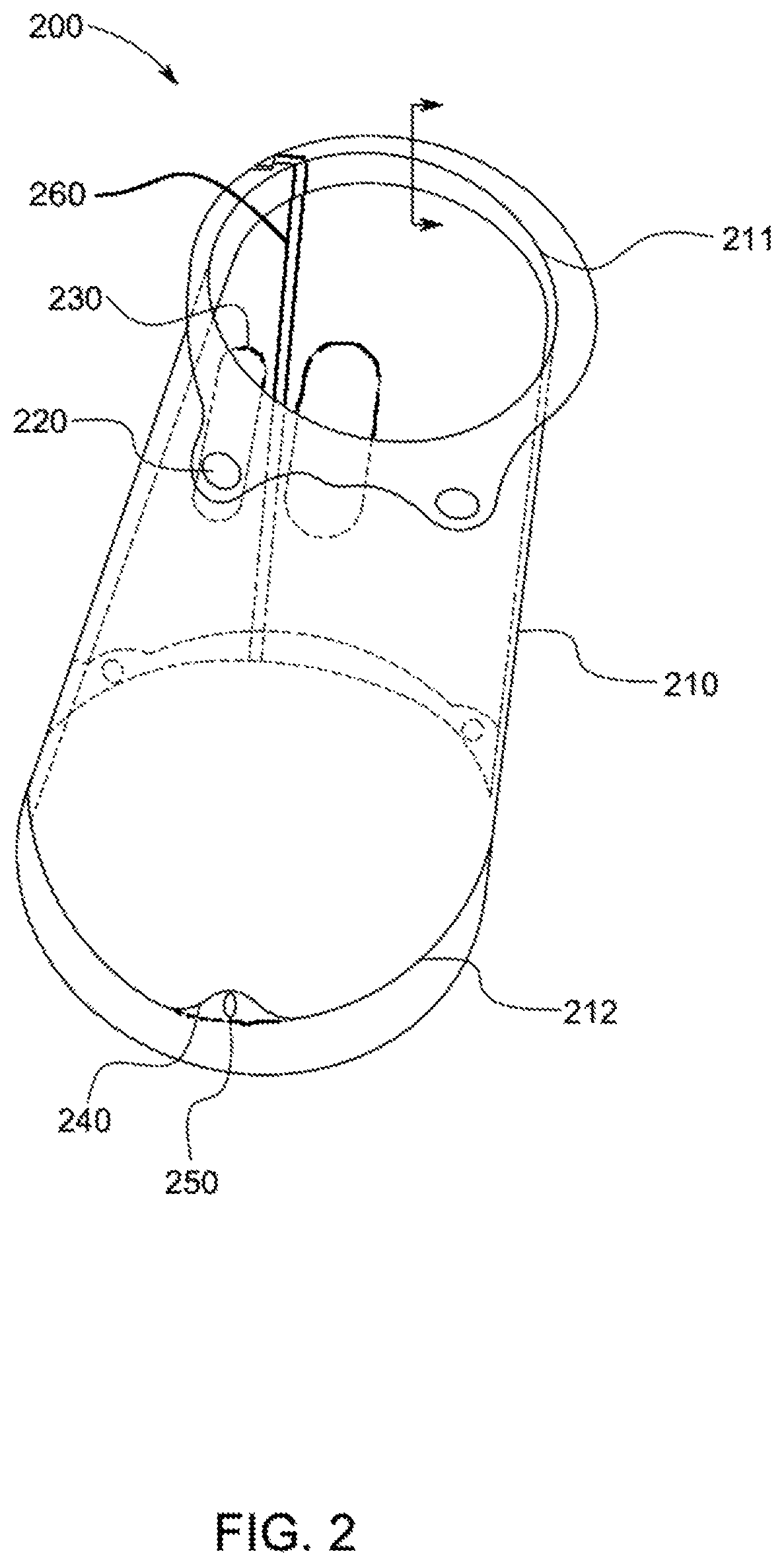
FIG. 2 illustrates a zoomed-in angled perspective view of a sleeve, according to an exemplary embodiment of the present general inventive concept;
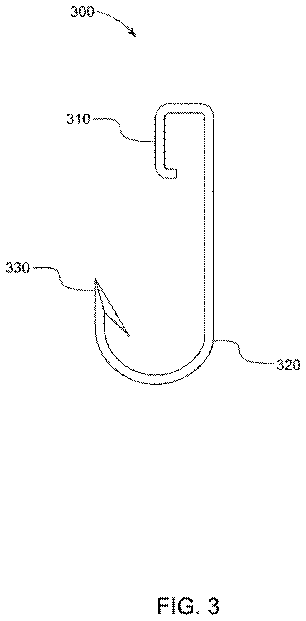
FIG. 3 illustrates a zoomed-in side view of a hook attached to the fish hauling device, according to an exemplary embodiment of the present general inventive concept;
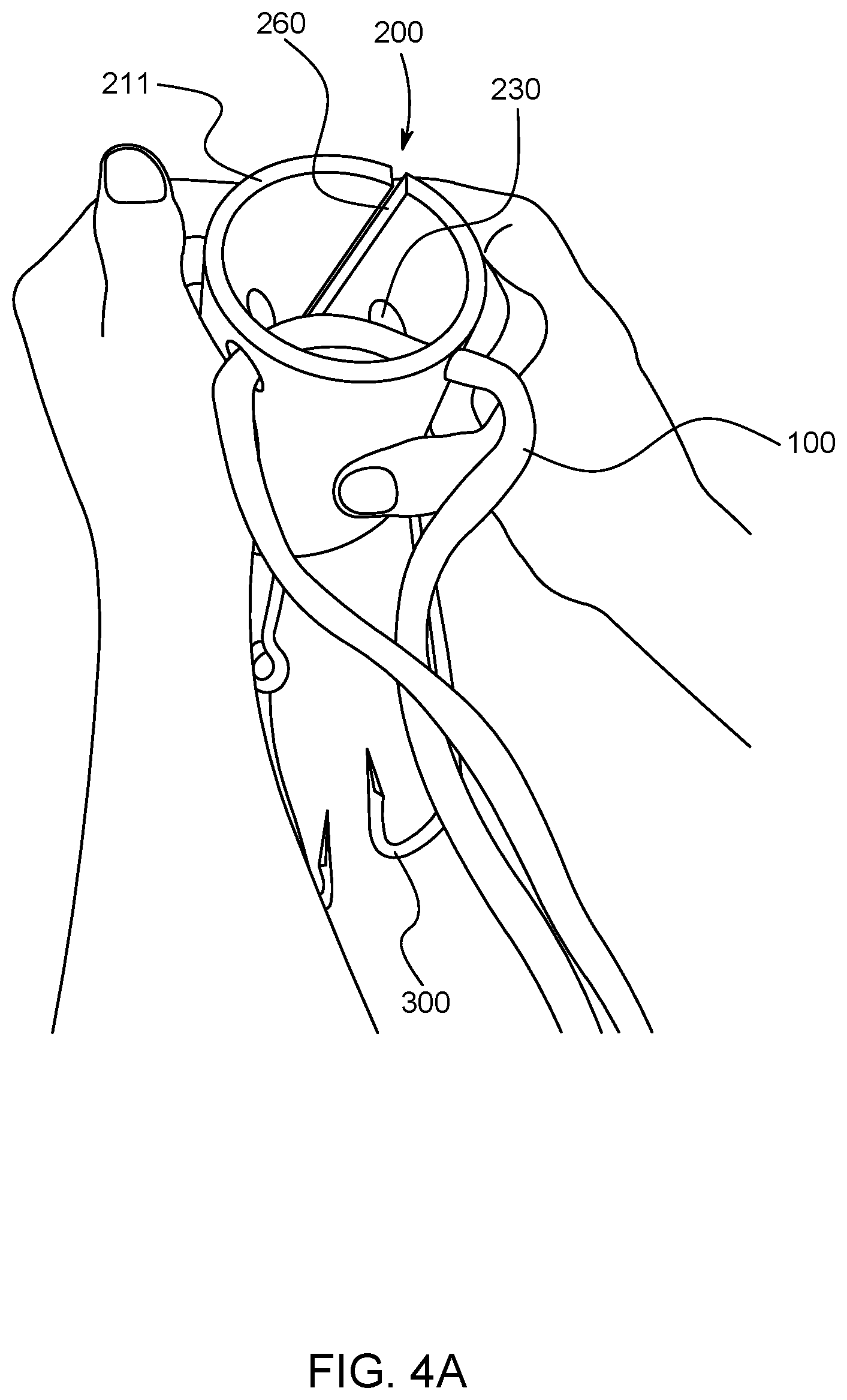
FIG. 4A illustrates a top angled perspective view of the fish hauling device being pulled apart at the split portion by a user utilizing the plurality of finger sots to allow a fishing line to be inserted therein, according to an exemplary embodiment of the present general inventive concept; and
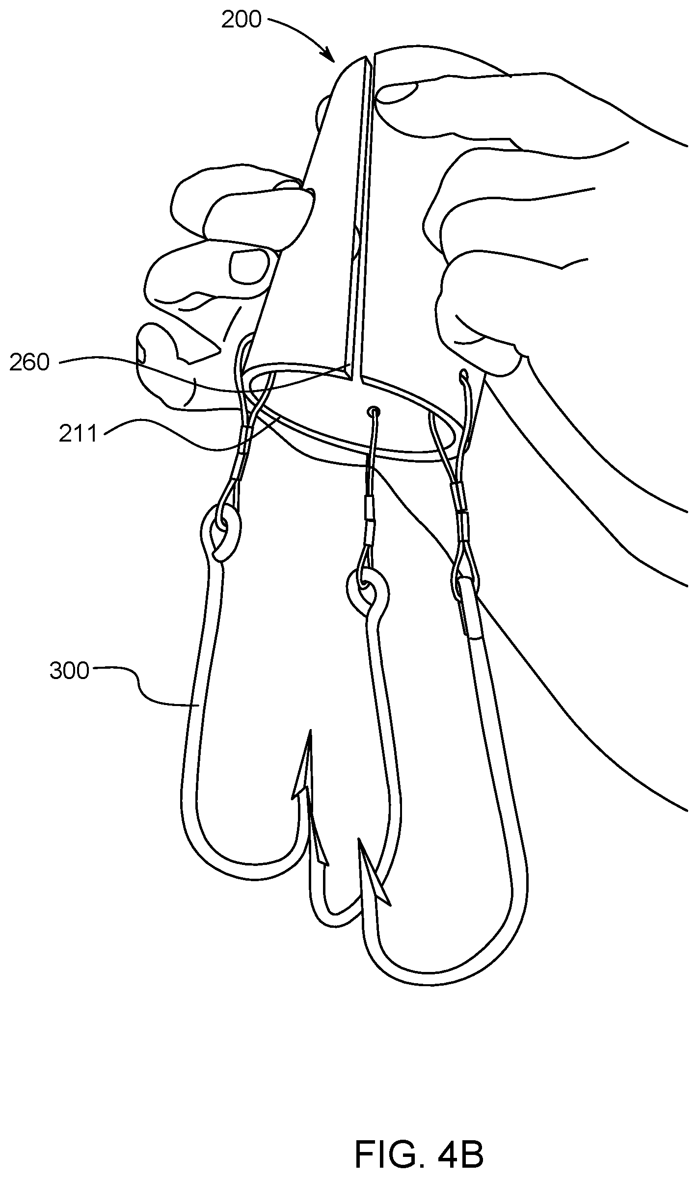
FIG. 4B illustrates a bottom angled perspective view of the fish hauling device being pulled apart at the split portion by a user utilizing the plurality of finger slots to allow a fishing line to be inserted therein, according to an exemplary embodiment of the present general inventive concept.
DETAILED DESCRIPTION
Various example embodiments (a.k.a., exemplary embodiments) will now be described more fully with reference to the accompanying drawings in which some example embodiments are illustrated. In the figures, the thicknesses of lines, layers and/or regions may be exaggerated for clarity.
Accordingly, while example embodiments are capable of various modifications and alternative forms, embodiments thereof are shown by way of example in the figures and will herein be described in detail. It should be understood, however, that there is no intent to limit example embodiments to the particular forms disclosed, but on the contrary, example embodiments are to cover all modifications, equivalents, and alternatives falling within the scope of the disclosure. Like numbers refer to like/similar elements throughout the detailed description.
It is understood that when an element is referred to as being "connected" or "coupled" to another element, it can be directly connected or coupled to the other element or intervening elements may be present. In contrast, when an element is referred to as being "directly connected" or "directly coupled" to another element, there are no intervening elements present. Other words used to describe the relationship between elements should be interpreted in a like fashion (e.g., "between" versus "directly between," "adjacent" versus "directly adjacent," etc.).
The terminology used herein is for the purpose of describing particular embodiments only and is not intended to be limiting of example embodiments. As used herein, the singular forms "a," "an" and "the" are intended to include the plural forms as well, unless the context clearly indicates otherwise. It will be further understood that the terms "comprises," "comprising," "includes" and/or "including," when used herein, specify the presence of stated features, integers, steps, operations, elements and/or components, but do not preclude the presence or addition of one or more other features, integers, steps, operations, elements, components and/or groups thereof.
Unless otherwise defined, all terms (including technical and scientific terms) used herein have the same meaning as commonly understood by one of ordinary skill in the art to which example embodiments belong. It will be further understood that terms, e.g., those defined in commonly used dictionaries, should be interpreted as having a meaning that is consistent with their meaning in the context of the relevant art. However, should the present disclosure give a specific meaning to a term deviating from a meaning commonly understood by one of ordinary skill, this meaning is to be taken into account in the specific context this definition is given herein.
FIG. 1 illustrates a fish hauling device 1, according to an exemplary embodiment of the present general inventive concept.
The fish hauling device 1 may include a rope 100, a sleeve 200, and a plurality of hooks 300, but is not limited thereto.
FIG. 2 illustrates a zoomed-in angled perspective view of the sleeve 200, according to an exemplary embodiment of the present general inventive concept.
FIG. 3 illustrates a zoomed-in side view of a hook 300 attached to the fish hauling device 100, according to an exemplary embodiment of the present general inventive concept.
The fish hauling device 100, and components thereof, may be constructed from metal, plastic, rope, cloth, polyester, cotton, wool, rubber, leather, faux-leather, hooks, loops, wiring, VELCRO, adhesives, and any other material known to one of ordinary skill in the art.
Referring to FIG. 2, the sleeve 200 may include a body 210, a plurality of rope attachment apertures 220, a plurality of finger slots 230, a plurality of slot indentations 240, a plurality of slots 250, and a split portion 260.
The body 210 may have a cylindrical shape, a rectangular prism shape, etc., but is not limited thereto, and may be constructed from plastic (e.g., high density plastic), metal, wood, or any other material known to one of ordinary skill in the art.
The body 210 may have various dimensions, and is not limited to width, length, circumference, thickness, or height.
The body 210 may include a first end 211 and a second end 212, which may include rims having open apertures.
The plurality of rope attachment apertures 220 may be disposed at the first end 211 of the body 210, in order to allow the rope 100 to be woven therethrough.
The plurality of finger slots 230 may be slots disposed throughout the body 110 to a user to easily grip the body 110 and to pull the body 110 apart along at the split portion 260.
The plurality of slot indentations 240 may be disposed at the second end 212 of the body 210, and may protrude inwards toward a center of the body 210.
The plurality of slots 250 may be also called hook mounting slots/apertures to allow the plurality of hooks 300 to each be mounted thereto, and may each be disposed at the second end 212 of the body 210 on at least a portion of the plurality of slot indentations 240.
The split portion 260 may be included along a length of the body 210, in order to allow a finishing line to be inserted within the body 210 without requiring the user to "thread" the fishing line through the first end 211 or the second end 212 of the body 210.
Referring to FIGS. 1 and 2, the plurality of hooks 300 may each be mounted to the plurality of slots 250 such that the plurality of hooks 300 are curved inwards, to allow for easier fish hoisting.
The hook 300, which is preferably provided in plurality, may include an attachment portion 310, a connecting portion 320, and a pointed end 330.
The attachment portion 310 may be connected, at a first end of the hook 300, to the sleeve 200 via the slot 250. More specifically, the attachment portion 310 may have a rounded shape to allow a portion of the hook 300 to enter the slot 250 (i.e., the attachment portion 310 loops through the slot 250 and wrap around a bottom end of the sleeve 200), such that the attachment portion is connected to a bottom portion of the sleeve 200.
The pointed end 330 may be disposed at a second end of the hook 300, and may be utilized to grab onto a fish as the fish is being hauled out the water.
The connecting portion 320 may be disposed between the attachment portion 310 and the pointed end 330, such that the hook 300 is curved along the connecting portion 320.
FIG. 4A illustrates a top angled perspective view of the fish hauling device 1 being pulled apart at the split portion 260 by a user utilizing the plurality of finger sots 230 to allow a fishing line to be inserted therein, according to an exemplary embodiment of the present general inventive concept.
FIG. 4B illustrates a bottom angled perspective view of the fish hauling device 1 being pulled apart at the split portion 260 by a user utilizing the plurality of finger slots 230 to allow a fishing line to be inserted therein, according to an exemplary embodiment of the present general inventive concept.
As illustrated in FIGS. 4A and 4B, the user may place a finger from a left hand into one of the plurality of finger slots 230, and another finger from a right hand into another one of the plurality of finger slots 230, and then use thumbs and or portions of hands of the user to apply pressure to the body 210 until the split portion 260 becomes larger, thereby allowing a fishing line to be inserted thereinside. As such, the split portion 260 may be disposed along a length of the body 210 between at least two of the plurality of finger slots 230 to allow a user to increase a size of the split portion 260 by pulling the body 210 apart using the plurality of finger slots 230.
Although a few embodiments of the present general inventive concept have been shown and described, it will be appreciated by those skilled in the art that changes may be made in these embodiments without departing from the principles and spirit of the general inventive concept, the scope of which is defined in the appended claims and their equivalents.
* * * * *
D00000
D00001
D00002
D00003
D00004
D00005
XML
uspto.report is an independent third-party trademark research tool that is not affiliated, endorsed, or sponsored by the United States Patent and Trademark Office (USPTO) or any other governmental organization. The information provided by uspto.report is based on publicly available data at the time of writing and is intended for informational purposes only.
While we strive to provide accurate and up-to-date information, we do not guarantee the accuracy, completeness, reliability, or suitability of the information displayed on this site. The use of this site is at your own risk. Any reliance you place on such information is therefore strictly at your own risk.
All official trademark data, including owner information, should be verified by visiting the official USPTO website at www.uspto.gov. This site is not intended to replace professional legal advice and should not be used as a substitute for consulting with a legal professional who is knowledgeable about trademark law.