Controlling data transmission in radio access networks
Eyuboglu Sept
U.S. patent number 10,785,791 [Application Number 14/961,448] was granted by the patent office on 2020-09-22 for controlling data transmission in radio access networks. This patent grant is currently assigned to CommScope Technologies LLC. The grantee listed for this patent is COMMSCOPE TECHNOLOGIES LLC. Invention is credited to Vedat Eyuboglu.


View All Diagrams
| United States Patent | 10,785,791 |
| Eyuboglu | September 22, 2020 |
Controlling data transmission in radio access networks
Abstract
An example communication system includes remote units, each which includes one or more radio frequency (RF) units to exchange RF signals with mobile devices, with at least some of the RF signals including information destined for, or originating from, a mobile device. A controller is separated from the remote units by one or more networks. The controller is connected to an external network, and is for implementing a scheduler. The scheduler is for allocating resources for transmission of data representing the information, and is configured to override a pending hybrid automatic repeat request (HARQ) transmission on a HARQ process by scheduling a new HARQ transmission on the HARQ process.
| Inventors: | Eyuboglu; Vedat (Weston, MA) | ||||||||||
|---|---|---|---|---|---|---|---|---|---|---|---|
| Applicant: |
|
||||||||||
| Assignee: | CommScope Technologies LLC
(Hickory, NC) |
||||||||||
| Family ID: | 1000001561930 | ||||||||||
| Appl. No.: | 14/961,448 | ||||||||||
| Filed: | December 7, 2015 |
| Current U.S. Class: | 1/1 |
| Current CPC Class: | H04W 72/1289 (20130101); H04L 1/1812 (20130101) |
| Current International Class: | H04W 72/12 (20090101); H04L 1/18 (20060101) |
References Cited [Referenced By]
U.S. Patent Documents
| 6711144 | March 2004 | Kim et al. |
| 6731618 | May 2004 | Chung et al. |
| 6741862 | May 2004 | Chung et al. |
| 6781999 | August 2004 | Eyuboglu et al. |
| 6985451 | January 2006 | Nattiv et al. |
| 7170871 | January 2007 | Eyuboglu et al. |
| 7200391 | April 2007 | Chung et al. |
| 7242958 | July 2007 | Chung et al. |
| 7277446 | October 2007 | Abi-Nassif et al. |
| 7299278 | November 2007 | Ch'ng |
| 7415242 | August 2008 | Ngan |
| 7515643 | April 2009 | Chung |
| 7558356 | July 2009 | Pollman et al. |
| 7558588 | July 2009 | To et al. |
| 7603127 | October 2009 | Chung et al. |
| 7626926 | December 2009 | Abi-Nassif et al. |
| 7672682 | March 2010 | Sharma et al. |
| 7715466 | May 2010 | Oh et al. |
| 7729243 | June 2010 | Ananthaiyer et al. |
| 7730189 | June 2010 | Harikumar et al. |
| 7751835 | July 2010 | Sharma et al. |
| 7801487 | September 2010 | Mehrabanzad et al. |
| 7831257 | November 2010 | Pollman et al. |
| 7835698 | November 2010 | Eyuboglu et al. |
| 7843892 | November 2010 | Mehrabanzad et al. |
| 7860513 | December 2010 | Chung et al. |
| 7907571 | March 2011 | Raghothaman et al. |
| 7920541 | April 2011 | To et al. |
| 7926098 | April 2011 | Chinitz et al. |
| 7933619 | April 2011 | Kim |
| 7934001 | April 2011 | Harikumar et al. |
| 7953040 | May 2011 | Harikumar et al. |
| 7983672 | July 2011 | Humblet et al. |
| 7983708 | July 2011 | Mehrabanzad et al. |
| 7995493 | August 2011 | Anderlind et al. |
| 8023439 | September 2011 | Rao |
| 8060058 | November 2011 | Ch'ng et al. |
| 8078165 | December 2011 | Mate et al. |
| 8085696 | December 2011 | Garg et al. |
| 8094630 | January 2012 | Garg et al. |
| 8099504 | January 2012 | Cherian et al. |
| 8111253 | February 2012 | Rao |
| 8130686 | March 2012 | Rao et al. |
| 8140091 | March 2012 | Chung et al. |
| 8145221 | March 2012 | Garg et al. |
| 8160020 | April 2012 | Eyuboglu et al. |
| 8160629 | April 2012 | Mate et al. |
| 8160631 | April 2012 | Raghothaman et al. |
| 8160829 | April 2012 | Kalenine |
| 8165528 | April 2012 | Raghothaman et al. |
| 8170598 | May 2012 | Raghothaman et al. |
| 8176327 | May 2012 | Xiong et al. |
| 8194597 | June 2012 | Feder et al. |
| 8195187 | June 2012 | Eyuboglu et al. |
| 8229397 | July 2012 | Hou et al. |
| 8229498 | July 2012 | Ch'ng et al. |
| 8259671 | September 2012 | Raghothaman et al. |
| 8280376 | October 2012 | Rajagopalan et al. |
| 8290527 | October 2012 | Richardson |
| 8295256 | October 2012 | Humblet et al. |
| 8295818 | October 2012 | Palnati et al. |
| 8311570 | November 2012 | Richardson |
| 8326342 | December 2012 | Raghothaman et al. |
| 8340636 | December 2012 | Yin et al. |
| 8345694 | January 2013 | Den et al. |
| 8346220 | January 2013 | Mate et al. |
| 8355727 | January 2013 | Hoang et al. |
| 8358623 | January 2013 | Samar et al. |
| 8379566 | February 2013 | Gao et al. |
| 8379625 | February 2013 | Humblet |
| 8385291 | February 2013 | Richardson et al. |
| 8400989 | March 2013 | Ch'ng et al. |
| 8402143 | March 2013 | Ramaswamy et al. |
| 8428601 | April 2013 | Samar et al. |
| 8452299 | May 2013 | Raghothaman |
| 8457084 | June 2013 | Valmikam et al. |
| 8503342 | August 2013 | Richardson |
| 8520659 | August 2013 | Humblet |
| 8532658 | September 2013 | Knisely |
| 8542707 | September 2013 | Hou et al. |
| 8543139 | September 2013 | Samar et al. |
| 8554231 | October 2013 | Jones |
| 8594663 | November 2013 | Ch'ng et al. |
| 8615238 | December 2013 | Eyuboglu et al. |
| 8615593 | December 2013 | Ch'ng et al. |
| 8619702 | December 2013 | Garg et al. |
| 8639247 | January 2014 | Ng et al. |
| 8688809 | April 2014 | Ch'ng et al. |
| 8693987 | April 2014 | Chiussi et al. |
| 8705483 | April 2014 | Liu |
| 8718697 | May 2014 | Srinivas et al. |
| 8731574 | May 2014 | Ch'ng et al. |
| 8750271 | June 2014 | Jones |
| 8774134 | July 2014 | Raghothaman et al. |
| 8781483 | July 2014 | Ch'ng |
| 8798680 | August 2014 | Kiiski et al. |
| 8805371 | August 2014 | Richardson et al. |
| 8843638 | September 2014 | Garg et al. |
| 8873512 | October 2014 | Richardson et al. |
| 8886249 | November 2014 | Richardson |
| 8909278 | December 2014 | Rao et al. |
| 8942136 | January 2015 | Humblet |
| 8953566 | February 2015 | Hegde et al. |
| 8958809 | February 2015 | Nama et al. |
| 8976794 | March 2015 | Xiong |
| 8982841 | March 2015 | Srinivasan |
| 9072120 | June 2015 | Voschina et al. |
| 9078284 | July 2015 | Richardson |
| 9130711 | September 2015 | He et al. |
| 9179360 | November 2015 | Vivanco |
| 9380466 | June 2016 | Eyuboglu et al. |
| 9414399 | August 2016 | Eyuboglu et al. |
| 9497131 | November 2016 | Koskinen et al. |
| 9602182 | March 2017 | Zhang et al. |
| 9877340 | January 2018 | Park et al. |
| 9936470 | April 2018 | Eyuboglu et al. |
| 10057916 | August 2018 | Barabell et al. |
| 10064072 | August 2018 | Eyuboglu et al. |
| 10142962 | November 2018 | Lee et al. |
| 2002/0128009 | September 2002 | Boch et al. |
| 2002/0154055 | October 2002 | Davis et al. |
| 2002/0194605 | December 2002 | Cohen et al. |
| 2003/0147348 | August 2003 | Jiang |
| 2004/0068571 | April 2004 | Ahmavaara |
| 2004/0146072 | June 2004 | Farmwald |
| 2004/0136373 | July 2004 | Bareis |
| 2004/0143442 | July 2004 | Knight |
| 2004/0224637 | November 2004 | Silva et al. |
| 2005/0025160 | February 2005 | Meier et al. |
| 2005/0043030 | February 2005 | Shariat et al. |
| 2005/0073964 | April 2005 | Schmidt et al. |
| 2005/0073987 | April 2005 | Wu |
| 2005/0157675 | July 2005 | Feder et al. |
| 2005/0180460 | August 2005 | Hirano et al. |
| 2006/0056459 | March 2006 | Stratton et al. |
| 2006/0056559 | March 2006 | Pleasant et al. |
| 2006/0209752 | September 2006 | Wijngaarden et al. |
| 2007/0023419 | February 2007 | Ptasienski et al. |
| 2007/0058683 | March 2007 | Futami et al. |
| 2007/0071006 | March 2007 | Bosch et al. |
| 2007/0086487 | April 2007 | Yasuda et al. |
| 2007/0140218 | June 2007 | Nair et al. |
| 2007/0207838 | September 2007 | Kuwahara et al. |
| 2007/0220573 | September 2007 | Chiussi et al. |
| 2007/0230419 | October 2007 | Raman et al. |
| 2007/0242648 | October 2007 | Garg et al. |
| 2008/0003988 | January 2008 | Richardson |
| 2008/0022180 | January 2008 | Kuo |
| 2008/0200202 | August 2008 | Monotojo et al. |
| 2008/0233886 | September 2008 | Kaminski |
| 2008/0240034 | October 2008 | Gollamudi |
| 2009/0009744 | April 2009 | Lohr et al. |
| 2009/0097444 | April 2009 | Lohr et al. |
| 2009/0135718 | May 2009 | Yeo |
| 2009/0149189 | June 2009 | Sammour et al. |
| 2009/0149221 | June 2009 | Liu et al. |
| 2009/0180423 | July 2009 | Kroener |
| 2009/0180435 | July 2009 | Sarkar |
| 2009/0265599 | October 2009 | Chae |
| 2009/0276542 | November 2009 | Aweya et al. |
| 2009/0287976 | November 2009 | Wang |
| 2009/0300453 | December 2009 | Sahara |
| 2009/0307554 | December 2009 | Marinier et al. |
| 2009/0310534 | December 2009 | Lindskog et al. |
| 2009/0316626 | December 2009 | Lee |
| 2009/0327829 | December 2009 | Yang |
| 2010/0011269 | January 2010 | Budianu |
| 2010/0011271 | January 2010 | Giancola |
| 2010/0034135 | February 2010 | Kim et al. |
| 2010/0037115 | February 2010 | Zheng |
| 2010/0062768 | March 2010 | Lindqvist et al. |
| 2010/0098010 | April 2010 | Kuo |
| 2010/0115367 | May 2010 | Hsu |
| 2010/0118777 | May 2010 | Yamada |
| 2010/0118781 | May 2010 | Petrovic et al. |
| 2010/0142494 | June 2010 | Hsu |
| 2010/0167718 | July 2010 | Chiussi et al. |
| 2010/0169732 | July 2010 | Wu |
| 2010/0185911 | July 2010 | Cheng |
| 2010/0234035 | September 2010 | Fujishima et al. |
| 2010/0246513 | September 2010 | Lindskog |
| 2010/0257419 | October 2010 | Sung et al. |
| 2011/0134862 | June 2011 | Huang et al. |
| 2011/0145672 | June 2011 | Jongren |
| 2011/0170517 | July 2011 | Bakker et al. |
| 2011/0182255 | July 2011 | Kim et al. |
| 2011/0194548 | August 2011 | Feder et al. |
| 2011/0194630 | August 2011 | Yang et al. |
| 2011/0211447 | September 2011 | Wang |
| 2011/0268007 | November 2011 | Barany et al. |
| 2011/0287791 | November 2011 | Fujishima et al. |
| 2011/0310802 | December 2011 | Song |
| 2012/0057572 | March 2012 | Evans et al. |
| 2012/0127947 | May 2012 | Usui |
| 2012/0140660 | June 2012 | Kang et al. |
| 2012/0147815 | June 2012 | Meyer |
| 2012/0176884 | July 2012 | Zhang et al. |
| 2012/0176966 | July 2012 | Ling |
| 2012/0176980 | July 2012 | Moon et al. |
| 2012/0176996 | July 2012 | Kim et al. |
| 2012/0177153 | July 2012 | Cheng |
| 2012/0183028 | July 2012 | Han et al. |
| 2012/0189074 | July 2012 | Jin et al. |
| 2012/0195284 | August 2012 | Mann |
| 2012/0207105 | August 2012 | Geirhofer et al. |
| 2012/0208581 | August 2012 | Ishida et al. |
| 2012/0213109 | August 2012 | Xu et al. |
| 2012/0250520 | October 2012 | Chen et al. |
| 2012/0250740 | October 2012 | Ling |
| 2012/0257570 | October 2012 | Jang |
| 2012/0264470 | October 2012 | Bajj et al. |
| 2012/0300635 | November 2012 | Jersenius |
| 2012/0300766 | November 2012 | Chen et al. |
| 2012/0327882 | December 2012 | Park |
| 2013/0016686 | January 2013 | Li |
| 2013/0034197 | February 2013 | Aweya et al. |
| 2013/0100948 | April 2013 | Irvine |
| 2013/0136053 | May 2013 | Kim |
| 2013/0136104 | May 2013 | Samar et al. |
| 2013/0194985 | August 2013 | Zetterman |
| 2013/0223307 | August 2013 | Ohlsson |
| 2013/0223365 | August 2013 | Choi et al. |
| 2013/0223391 | August 2013 | Koo |
| 2013/0242837 | September 2013 | Yang |
| 2013/0242919 | September 2013 | Koo |
| 2013/0250869 | September 2013 | Eriksson |
| 2013/0279452 | October 2013 | Liu |
| 2103/0294403 | November 2013 | Srinivasan |
| 2013/0322270 | December 2013 | Ko |
| 2014/0003389 | January 2014 | Wang et al. |
| 2014/0031036 | January 2014 | Koo |
| 2014/0044057 | February 2014 | Gaal et al. |
| 2014/0071868 | March 2014 | Bergquist |
| 2014/0086112 | March 2014 | Stern-Berkowitz |
| 2014/0098797 | April 2014 | Kanamarlapudi et al. |
| 2014/0126438 | May 2014 | Zhu et al. |
| 2014/0161070 | June 2014 | Chang et al. |
| 2014/0162664 | June 2014 | Stapleton et al. |
| 2014/0177549 | June 2014 | Knisely |
| 2014/0211690 | July 2014 | Nama et al. |
| 2014/0212269 | July 2014 | Kastner et al. |
| 2014/0219162 | August 2014 | Eyuboglu et al. |
| 2014/0219255 | August 2014 | Eyuboglu et al. |
| 2014/0219267 | August 2014 | Eyuboglu et al. |
| 2014/0321406 | October 2014 | Marinier |
| 2015/0011219 | January 2015 | Saily et al. |
| 2015/0023284 | January 2015 | Zhao et al. |
| 2015/0085720 | March 2015 | Gaal et al. |
| 2015/0085796 | March 2015 | Xu |
| 2015/0172023 | June 2015 | Yang et al. |
| 2015/0193282 | July 2015 | Blocksome |
| 2015/0256297 | September 2015 | Yang et al. |
| 2015/0304960 | October 2015 | Yang et al. |
| 2015/0373729 | December 2015 | Lee et al. |
| 2016/0037550 | February 2016 | Barabell et al. |
| 2016/0044548 | February 2016 | Choi et al. |
| 2016/0302088 | October 2016 | Eyuboglu et al. |
| 2016/0345342 | November 2016 | Eyuboglu et al. |
| 2017/0135121 | May 2017 | Eyuboglu et al. |
| 2017/0163330 | June 2017 | Raleigh et al. |
| 2017/0317790 | November 2017 | Yao |
| 2018/0007709 | January 2018 | Seo |
| 2019/0069190 | February 2019 | Eyuboglu et al. |
| 2019/0075576 | March 2019 | Eyuboglu et al. |
| 101044773 | Sep 2007 | CN | |||
| 101622811 | Jan 2010 | CN | |||
| 102340823 | Feb 2012 | CN | |||
| 102347827 | Feb 2012 | CN | |||
| 1134935 | Nov 2008 | EP | |||
| 2352264 | Aug 2011 | EP | |||
| 2787646 | Oct 2014 | EP | |||
| 2014124160 | Aug 2014 | WO | |||
| 2014153125 | Sep 2014 | WO | |||
| 2015191530 | Dec 2015 | WO | |||
Other References
|
United States Patent and Trademark Office, "Office Action", "From U.S. Appl. No. 15/230,936", dated Jun. 15, 2017, pp. 1-60, Published in: US. cited by applicant . United States Patent and Trademark Office, "Advisory Action", "From U.S. Appl. No. 14/734,311", dated Jun. 20, 2017, pp. 1-2, Published in: US. cited by applicant . U.S. Patent Office, "Notice of Allowance", "from U.S. Appl. No. 13/762,284", dated May 8, 2015, pp. 1-5, Published in: US. cited by applicant . U.S. Patent Office, "Notice of Allowance", "from U.S. Appl. No. 13/762,284", dated Aug. 26, 2015, pp. 1-12, Published in: US. cited by applicant . U.S. Patent Office, "Notice of Allowance", "from U.S. Appl. No. 13/762,284", dated Dec. 18, 2015, pp. 1-7, Published in: US. cited by applicant . U.S. Patent Office, "Notice of Allowance", "from U.S. Appl. No. 13/762,284", dated Feb. 25, 2016, pp. 1-6, Published in: US. cited by applicant . U.S. Patent Office, "Office Action", "from U.S. Appl. No. 13/762,284", dated Oct. 23, 2014, pp. 1-14, Published in: US. cited by applicant . European Patent Office, "Office Action from EP Application No. 14707024.7", "from Foreign Counterpart to U.S. Appl. No. 13/762,283", dated Oct. 5, 2016, pp. 1-6, Published in: EP. cited by applicant . European Patent Office, "European Search Report for EP Application No. 16175955.0", "Foreign Counterpart from U.S. Application No. 16175955.0", dated Oct. 10, 2016, pp. 1-10, Published in: EP. cited by applicant . European Patent Office, "European Search Report for EP Application No. 16175956.8", "Foreign counterpart to U.S. Appl. No. 13/762,283", dated Oct. 10, 2016, pp. 1-10, Published in: EP. cited by applicant . U.S. Patent Office, "Final Office Action", "from U.S. Appl. No. 13/762,283", dated Aug. 21, 2015, pp. 1-47, Published in: US. cited by applicant . U.S. Patent Office, "Notice of Allowance", "from U.S. Appl. No. 13/762,283", dated Apr. 1, 2016, pp. 1-9, Published in: US. cited by applicant . U.S. Patent Office, "Office Action", "from U.S. Appl. No. 13/762,283", dated Nov. 21, 2014, pp. 1-39, Published in: US. cited by applicant . U.S. Patent Office, "Office Action", "from U.S. Appl. No. 15/230,936", dated Jan. 12, 2017, pp. 1-10, Published in: US. cited by applicant . International Search Authority, "International Search Report and Written Opinion for PCT Application No. PCT/US2014/015137", "from Foreign Counterpart to U.S. Appl. No. 13/762,283", dated Sep. 22, 2014, pp. 1-18, Published in: WO. cited by applicant . U.S. Patent Office, "Advisory Action", "from U.S. Appl. No. 13/762,292", dated Feb. 6, 2017, pp. 1-4, Published in: US. cited by applicant . U.S. Patent Office, "Final Office Action", "from U.S. Appl. No. 13/762,292", dated Sep. 27, 2016, pp. 1-18, Published in: US. cited by applicant . U.S. Patent Office, "Office Action", "from U.S. Appl. No. 13/762,292", dated Dec. 30, 2015, pp. 1-25, Published in: US. cited by applicant . U.S. Patent Office, "Pre-Appeal Brief Conference Decision", "from U.S. Appl. No. 13/762,292", dated Apr. 12, 2017, pp. 1-6, Published in: US. cited by applicant . U.S. Patent Office, "Restriction Requirement", "from U.S. Appl. No. 13/762,292", dated May 27, 2015, pp. 1-6, Published in: US. cited by applicant . U.S. Patent Office, "Final Office Action", "from U.S. Appl. No. 14/734,311", dated Apr. 7, 2017, pp. 1-52, Published in: US. cited by applicant . U.S. Patent Office, "Office Action", "from U.S. Appl. No. 14/734,311", dated Jul. 14, 2016, pp. 1-64, Published in: US. cited by applicant . International Search Authority, "International Search Report and Written Opinion for PCT Application No. PCT/US2015/034829", "from Foreign Counterpart to U.S. Appl. No. 14/734,311", dated Dec. 8, 2015, pp. 1-14, Published in: WO. cited by applicant . International Search Authority, "International Search Report and Written Opinion for PCT Application No. PCT/US2016/064750", "from Foreign Counterpart U.S. Appl. No. 14/961,448", dated Mar. 8, 2017, pp. 1-14, Published in: US. cited by applicant . "3rd Generation Partnership Project; Technical Specification Group Radio Access Network; Evolved Universal Terrestrial Radio Access (E-UTRA); Base Station (BS) radio transmission and reception (Release 8)", "3GPP TS 36.104 V8.0.0", Dec. 2007, pp. 1-47. cited by applicant . "3rd Generation Partnership Project Techinical Specification Group Radio Access Network Evolved Universal Terrestrial Radio Access (E-UTRA) Requirement for Support of Radio Resource Management (Release 8), 3GPP TS 36.133 V8.1.0", Mar. 2008, p. 25 Publisher: 3GPP. cited by applicant . Belhouchet et al., "ITU/BDT Arab Regional Workshop on '4G Wireless Systems' LTE Technology: Session 3: LTE Overview-Design Targets and Multiple Access Technologies", "Tunisia", Jan. 27-29, 2010, pp. 1-82. cited by applicant . Dotsch et al., "Quantitative Analysis of Split Base Station Processing and Determination of Advantageous Architectures for LTE", "Published online: Wiley Online Library (wileyonlinelibrary.com)", 2013, pp. 105-128, Publisher: Bell Labs Technical Journal 18(1). cited by applicant . Garner, Geoffrey M., "IEEE 1588 Version 2", Sep. 24, 2008, p. 89. cited by applicant . Haberland, Bernd et al., "Base Stations in the Cloud", "alcatel-lucent.com", Sep. 28, 2012, pp. 1-23, Publisher: Alcatel-Lucent. cited by applicant . Ma et al., "Radiostar: Providing Wireless Coverage Over Gigabit Ethernet", "Bell Labs Technical Journal; Published online in Wiley InterScience (www.interscienc.e.wiley.com)", 2009, pp. 7-24, Publisher: Alcatel-Lucent. cited by applicant . "Small Cell Virtualization Functional Splits and Use Cases 159.05.1.01", "www.smallcellforum.org", Jun. 2015, pp. 58, Publisher: Small Cell Forum. cited by applicant . Zhu, Zhenbo et al., "Virtual Base Station Pool: Towards a Wireless Network Cloud for Radio Access Networks", May 3, 2011, pp. 1-10, Publisher: IBM Research, Published in: Yorktown Heights, US. cited by applicant . Small Cell Forum, "Small Cell Virtualization Functional Splits and Use Cases", 159.05.1.01, Small Cell Forum Release, www.smallcellforum.org, Jun. 2015 (58 pages). cited by applicant . Dotsch, Uwe, et al., "Quantitative Analysis of Split Station Processing and Determination of Advantageous Architectures for LTE", Bell Labs Technical Journal 18(1), 105-128, Alcatel-Lucent. Published by Wiley Periodicals, Inc., Published online in Wiley Online Library (wileyonlinelibrary.com), DOI: 10.1002/bltj.2159, copyright 2013 (24 pages). cited by applicant . U.S. Patent and Trademark Office, "Office Action", "from U.S. Appl. No. 15/189,473", dated Dec. 13, 2017, pp. 1-53, Published in: US. cited by applicant . U.S. Patent and Trademark Office, "Corrected Notice of Allowability", "from U.S. Appl. No. 13/762,292", dated Dec. 15, 2017, pp. 1-6, Published in: US. cited by applicant . U.S. Patent and Trademark Office, "Notice of Allowance and Fee(s) Due", "from U.S. Appl. No. 13/762,292", dated Nov. 30, 2017, pp. 1-31, Published in: US. cited by applicant . U.S. Patent and Trademark Office, "Notice of Allowance and Fee(s) Due", "from U.S. Appl. No. 14/734,311", dated Dec. 14, 2017, pp. 1-14, Published in: US. cited by applicant . U.S. Patent and Trademark Office, "Final Office Action", "From U.S. Appl. No. 15/230,936", dated Nov. 8, 2017, pp. 1-48, Published in: US. cited by applicant . United States Patent and Trademark Office, "Notice of Allowance", "From U.S. Appl. No. 14/734,311", dated Aug. 23, 2017, pp. 1-19, Published in: US. cited by applicant . United States Patent and Trademark Office, "Notice of Allowance", "From U.S. Appl. No. 13/762,292", dated Jul. 28, 2017, pp. 1-8, Published in: US. cited by applicant . European Patent Office, "Communication Pursuant to Article 94(3) for EP Application No. 15731443.6", "Foreign Counterpart to U.S. Appl. No. 14/734,311", dated Mar. 21, 2018, pp. 1-7, Published in: EP. cited by applicant . Australian Government IP Australia, "Examination Report from AU Application No. 2015274867 dated Sep. 24, 2018", from Foreign Counterpart to PCT Application No. PCT/US2015/034829, dated Sep. 24, 2018, pp. 1-3, Published: AU. cited by applicant . European Patent Office, "Communication Pursuant to Article 94(3) from EP Application No. 14707024.7 dated May 2, 2018", "from Foreign Counterpart of U.S. Appl. No. 13/762,283", dated May 2, 2018, p. 1-5, Published in: EP. cited by applicant . European Patent Office, "Notice of Publication from EP Application No. 14707024.7 dated Nov. 18, 2015", from Foreign Counterpart to U.S. Appl. No. 13/762,284, dated Nov. 18, 2015, p. 1 Published: EP. cited by applicant . International Bureau, "International Preliminary Report on Patentability from PCT Application No. PCT/US2014/015137 dated Aug. 20, 2015", from Foreign Counterpart to U.S. Appl. No. 13/762,284, dated Aug. 20, 2015, pp. 1-13, Published: Switzerland. cited by applicant . International Searching Authority, "International Preliminary Report on Patentability from PCT Application No. PCT/US2015/034829 dated Dec. 22, 2016", "from Foreign Counterpart of U.S. Appl. No. 14/734,311", dated Dec. 22, 2016, p. 1-11, Published in: WO. cited by applicant . International Searching Authority, "International Preliminary Report on Patentability from PCT Application No. PCT/US2016/064750 dated Jun. 21, 2018", "from Foreign Counterpart of U.S. Appl. No. 14/961,448", dated Jun. 21, 2016, pp. 1-11, Published in: WO. cited by applicant . International Searching Authority, "Invitation to Pay Addition Fees from PCT Application No. PCT/US2014/015137 dated Aug. 4, 2014", from Foreign Counterpart to U.S. Appl. No. 13/762,284, dated Aug. 4, 2014, pp. 1-8, Published: EP. cited by applicant . International Searching Authority, "Invitation to Pay Additional Fees from PCT Application No. PCT/US2015/034829 dated Oct. 1, 2015", from Foreign Counterpart to U.S. Appl. No. 14/734,311, dated Oct. 1, 2015, pp. 1-6, Published: EP. cited by applicant . U.S. Patent and Trademark Office, "Corrected Notice of Allowability from U.S. Appl. No. 15/230,936 dated Aug. 24, 2018" p. 1-10, Published in: US. cited by applicant . U.S. Patent and Trademark Office, "Corrected Notice of Allowability", U.S. Appl. No. 15/191,005, dated Aug. 15, 2018, pp. 1-6, Published: US. cited by applicant . U.S. Patent and Trademark Office, "Examiner-Initiated Interview Summary from U.S. Appl. No. 14/734,311 dated Mar. 23, 2017", p. 1-1, Published in: US. cited by applicant . U.S. Patent and Trademark Office, "Notice of Allowability", U.S. Appl. No. 14/734,311, dated May 1, 2018, pp. 1-8, Published: US. cited by applicant . U.S. Patent and Trademark Office, "Notice of Allowance from U.S. Appl. No. 15/191,005 dated Jan. 31, 2018" p. 1-10, Published in: US. cited by applicant . U.S. Patent and Trademark Office, "Notice of Allowance", U.S. Appl. No. 14/734,311, dated Apr. 19, 2018, pp. 1-12, Published: US. cited by applicant . U.S. Patent and Trademark Office, "Notice of Allowance", U.S. Appl. No. 15/189,473, datd Apr. 25, 2018, pp. 1-13, Published: US. cited by applicant . U.S. Patent and Trademark Office, "Notice of Allowance", U.S. Appl. No. 15/191,005, dated Mar. 20, 2018, pp. 1-13, Published: US. cited by applicant . U.S. Patent and Trademark Office, "Notice of Allowance", U.S. Appl. No. 15/230,936, dated Oct. 29, 2018, pp. 1-15, Published: US. cited by applicant . U.S. Patent and Trademark Office, "Notice of Allowance", U.S. Appl. No. 15/230,936, dated Jul. 2, 2018, pp. 1-15, Published in: US. cited by applicant . U.S. Patent and Trademark Office, "Notice of Allowance", U.S. Appl. No. 15/231,384, dated Nov. 28, 2018, pp. 1-15, Published: US. cited by applicant . U.S. Patent and Trademark Office, "Office Action", U.S. Appl. No. 15/191,005, dated Sep. 27, 2017, pp. 1-48, Published: US. cited by applicant . U.S. Patent and Trademark Office, "Office Action", U.S. Appl. No. 15/231,384, dated Jul. 12, 2018, pp. 1-82, Published: US. cited by applicant . U.S. Patent and Trademark Office, "Supplemental Notice of Allowability from U.S. Appl. No. 15/189,473 dated Jun. 13, 2018" p. 1-8, Published in: US. cited by applicant . U.S. Patent and Trademark Office, "Supplemental Notice of Allowability from U.S. Appl. No. 15/189,473 dated Jun. 5, 2018" p. 1-6, Published in: US. cited by applicant . U.S. Patent and Trademark Office, "Supplemental Notice of Allowability from U.S. Appl. No. 15/191,005 dated Mar. 29, 2018" p. 1-6, Published in: US. cited by applicant . U.S. Patent and Trademark Office, "Supplemental Notice of Allowability from U.S. Appl. No. 15/191,005 dated Apr. 11, 2018" pp. 1-8, Published in: US. cited by applicant . U.S. Patent and Trademark Office, "Supplemental Notice of Allowability from U.S. Appl. No. 15/191,005 dated Jun. 5, 2018" pp. 1-6, Published in: US. cited by applicant . United States Patent and Trademark Office, "Corrected Notice of Allowability for U.S. Appl. No. 15/230,936", dated Mar. 9, 2018, pp. 1-26, Published in: US. cited by applicant . U.S. Patent and Trademark Office, "Notice of Allowance", U.S. Appl. No. 15/230,936, dated Apr. 22, 2019, pp. 1-13, Published: US. cited by applicant . Australian Government IP Australia, "Notice of Acceptance for patent application from AU Application No. 2015274867 dated Apr. 16, 2019", from Foreign Counterpart to U.S. Appl. No. 14/734,311, pp. 1-3, Published: AU. cited by applicant . United States Patent and Trademark Office, "Notice of Allowance for U.S. Appl. No. 15/230,936", dated Feb. 9, 2018, pp. 1-10, Published in: US. cited by applicant . European Patent Office, "Extended European Search Report from EP Application No. 16873637.9 dated Jul. 5, 2019", from Foreign Counterpart to U.S. Appl. No. 14/961,448, pp. 1-13, Published: EP. cited by applicant . U.S. Patent and Trademark Office, "Office Action", U.S. Appl. No. 16/040,253, dated Feb. 1, 2019, pp. 1-68, Published: US. cited by applicant . European Patent Office, "Communication pursuant to Article 94(3) from EP Application No. 15731443.6 dated Feb. 5, 2019", from Foreign Counterpart to U.S. Appl. No. 14/734,311, dated Feb. 5, 2019, pp. 1-5, Published: EP. cited by applicant . U.S. Patent and Trademark Office, "Notice of Allowance", U.S. Appl. No. 16/040,253, dated Sep. 18, 2019, pp. 1-17, Published: US. cited by applicant . U.S. Patent and Trademark Office, "Office Action", U.S. Appl. No. 16/152,255, dated Jan. 2, 2020, pp. 1-93, Published: US. cited by applicant . U.S. Patent and Trademark Office, "Office Action", U.S. Appl. No. 16/152,266, dated Jan. 2, 2020, pp. 1-86, Published: US. cited by applicant . U.S. Patent and Trademark Office, "Office Action", U.S. Appl. No. 16/182,392, dated Dec. 31, 2019, pp. 1-105, Published: US. cited by applicant . U.S. Patent and Trademark Office, "Notice of Allowance", U.S. Appl. No. 15/230,936, dated Aug. 9, 2019, pp. 1-22, Published: US. cited by applicant . European Patent Office, "Communication under Rule 71(3) from EP Application No. 16873637.9", from Foreign Counterpart to U.S. Appl. No. 14/961,448, dated Mar. 9, 2020, pp. 1 through 45, Published: EP. cited by applicant . European Patent Office, "Communication pursuant to Article 94(3) from EP Application No. 16175955.0", from Foreign Counterpart to U.S. Appl. No. 13/762,283, dated Feb. 10, 2020, pp. 1-6, Published: EP. cited by applicant . Foreign European Patent Office, "Communication pursuant to Article 94(3) from EP Application No. 16175956.8", from Foreign Counterpart to U.S. Appl. No. 13/762,283, dated Feb. 10, 2020, pp. 1-8, Published: EP. cited by applicant . 3GPP, "ARQ operation with HARQ-ARQ interaction", Nokia, 3GPP TSG-RAN WG2 Meeting #55, Oct. 2006, pp. 1 through 8, 3GPP, Seoul, Korea. cited by applicant . China National Intellectual Property Administration, "First Office Action from CN Application No. 201680080837.9", from Foreign Counterpart to U.S. Appl. No. 14/961,448, dated Jun. 30, 2020, pp. 1 through 31, Published: CN. cited by applicant. |
Primary Examiner: Holland; Jenee
Attorney, Agent or Firm: Fogg & Powers LLC
Claims
What is claimed is:
1. A communication system comprising: remote units, each of the remote units comprising one or more radio frequency (RF) units to exchange RF signals with mobile devices, at least some of the RF signals comprising information destined for, or originating from, a mobile device; and a controller separated from the remote units by one or more networks, the controller being connected to an external network, the controller for implementing a scheduler, the scheduler for allocating resources for transmission of data representing the information, and the scheduler being configured to override a pending hybrid automatic repeat request (HARQ) transmission sent by the mobile device on a HARQ process by scheduling a new HARQ transmission on the HARQ process; wherein the controller is configured to accelerate retransmission of data in the overridden HARQ transmission sent by the mobile device by performing operations comprising: detecting, at a media access control instance of the controller, an unrecoverable error for the overridden HARQ transmission sent by the mobile device; sending a cross-layer indication to a radio link control instance in the controller to place a timer in an expired state, resulting in transmission of a status message to the mobile device, the status message indicating an error in the data; and receiving, from the mobile device, a retransmission of the data in response to the status message.
2. The communication system of claim 1, wherein the mobile device is configured to operate in a subframe bundling mode.
3. A communication system comprising: remote units, each of the remote units comprising one or more radio frequency (RF) units to exchange RF signals with mobile devices, at least some of the RF signals comprising information destined for, or originating from, a mobile device; and a controller separated from the remote units by one or more networks, the controller being connected to an external network, the controller for implementing a scheduler, the scheduler for allocating resources for transmission of data representing the information by the mobile device, and the controller being configured to cause the mobile device to accelerate retransmission of the data by performing operations comprising: detecting, at a media access control instance of the controller, an unrecoverable error for the transmission of the data by the mobile device; sending a cross-layer indication to a radio link control instance in the controller to place a timer in an expired state, resulting in transmission of a status message to the mobile device, the status message indicating an error in the data; and receiving, from the mobile device, a retransmission of the data in response to the status message.
4. The communication system of claim 3, wherein the mobile device is configured to operate in a subframe bundling mode.
5. A method for use with a communication system that includes remote units, each of the remote units comprising one or more radio frequency (RF) units to exchange RF signals with mobile devices, at least some of the RF signals comprising information destined for, or originating from, a mobile device; and a controller separated from the remote units by one or more networks, the controller being connected to an external network, the controller for implementing a scheduler, the scheduler for allocating resources for transmission of data representing the information by the mobile device, the method comprising: in order to accelerate retransmission of the data: detecting, at a media access control instance of the controller, an unrecoverable error for the transmission of the data by the mobile device; sending a cross-layer indication to a radio link control instance in the controller to place a timer in an expired state, resulting in transmission of a status message to the mobile device, the status message indicating an error in the data; and receiving, from the mobile device, a retransmission of the data in response to the status message.
6. The method of claim 5, wherein the mobile device is configured to operate in a subframe bundling mode.
Description
TECHNICAL FIELD
This disclosure relates to controlling data transmissions in radio access networks (RANs).
BACKGROUND
The widespread use of mobile devices, such as smartphones, has increased the demand for mobile data transmission capacity and for consistent and high-quality radio frequency (RF) coverage at in-building and other densely populated locations. Centralized radio access network (C-RAN) systems are being considered to meet this demand. In some implementations of C-RAN, a controller unit (CU) performs the majority of baseband processing, and remote units (RUs) perform RF processing and the remaining part of baseband processing. In C-RAN systems that support the long term evolution (LTE) standard, baseband processing in the CU may include critical real-time scheduling and hybrid automatic repeat request (HARQ) termination functions. This may place a constraint on the maximum round-trip latency that can be tolerated in the fronthaul network that is used to connect the CU and the RUs. In some cases, round-trip latency should be below a certain threshold, such as one millisecond (ms), to meet the most stringent timing requirement for HARQ. Such low latency may be achievable when the fronthaul network uses dedicated high-speed point-to-point links or a switched Ethernet network with low-latency switches. But, in other data networks that can be used in the fronthaul network in a C-RAN system, round-trip latency may exceed the threshold.
SUMMARY
An example communication system includes remote units, each which includes one or more radio frequency (RF) units to exchange RF signals with mobile devices, with at least some of the RF signals including information destined for, or originating from, a mobile device. In the example communication system, a controller is separated from the remote units by one or more networks. The controller is connected to an external network, and implements a scheduler. The scheduler is for allocating resources for transmission of data representing the information, and is configured to override a pending hybrid automatic repeat request (HARQ) transmission on a HARQ process by scheduling a new HARQ transmission on the HARQ process. The example communication system may include one or more of the following features, either alone or in combination.
The controller may be configured to accelerate retransmission of data in the HARQ transmission that was overridden. The scheduler may be configured to override the pending HARQ transmission for a mobile device when the scheduler does not have enough data waiting to be scheduled from other mobile devices having available HARQ processes to utilize all available radio link resources.
The controller may be configured to accelerate retransmission of data in the HARQ transmission that was overridden by performing operations that include: receiving, at the controller, an indication that data in the HARQ transmission that was overridden was not correctly received by the mobile device; in response to the indication, causing a radio link control instance associated with the mobile device to set a polling bit for the mobile device, with the polling bit for triggering transmission of a status message from the mobile device, and with the status message indicating an error in one or more data packets received by the mobile device; and receiving the status message from the mobile device.
The controller may be configured to accelerate retransmission of data in the HARQ transmission that was overridden by performing operations that include: receiving, at the controller, an indication that data in the HARQ transmission that was overridden was not correctly received by the mobile device; and in response to the indication, causing a radio link control (RLC) instance associated with the mobile device to retransmit, absent receipt of a status message, the data in the HARQ transmission that was overridden.
The controller may be configured to accelerate retransmission of data in the HARQ transmission that was overridden by performing operations that include: receiving, at the controller, an indication that data in the HARQ transmission that was overridden was not correctly received by the mobile device; and in response to the indication, causing the controller to retransmit data that is, at least in part, identical to the data that was overridden as part of a one or more new HARQ transmissions. Retransmitting the data may include: prioritizing transmission of the one or more new HARQ transmissions; and assigning physical downlink shared channel (PDSCH) resource blocks to the one or more new HARQ transmissions, with downlink control information being sent to the mobile device and comprising a new data indicator bit set to indicate a new HARQ transmission.
The controller may be configured to accelerate retransmission of data in the HARQ transmission that was overridden by performing operations that include configuring the mobile device to include a timer that runs until expiration, with the timer having a value to delay transmission of a status message from the mobile device to the controller by a radio link control instance.
The controller may be configured to accelerate retransmission of data in the HARQ transmission that was overridden by performing operations that include: triggering transmission of a status message to the mobile device via a radio link control instance upon detecting that data in the HARQ transmission that was overridden was not correctly received, with the status message indicating an error in the data; and receiving, from the mobile device and in response to the status message, a retransmission of data in the HARQ transmission that was overridden.
An example communication system may include remote units, each of which includes one or more radio frequency (RF) units to exchange RF signals with mobile devices, with at least some of the RF signals including information destined for, or originating from, a mobile device. The example communication system includes a controller separated from the remote units by one or more networks. The controller is connected to an external network, and implements a scheduler. The scheduler is for allocating resources for transmission of data representing the information. The controller is configured to cause the mobile device to accelerate retransmission of the data in response to an indication of an error in transmission of the data. The example communication system may include one or more of the following features, either alone or in combination.
The data may be part of a hybrid automatic repeat request (HARQ) transmission that was overridden, and the controller may be configured to accelerate retransmission of the data by performing operations that include receiving, at the controller a negative cyclic redundancy check (CRC) report for the HARQ transmission that was overridden. The controller may be configured to trigger transmission of a status message in response to the negative CRC report, the status message indicating an error in the data.
The data may be part of a hybrid automatic repeat request (HARQ) transmission that was overridden, and the controller may be configured to accelerate retransmission of the data by performing operations that include: weaving triggering transmission of a status message to the mobile device into normal operations of a radio link control instance in the controller, with the status message indicating the error in data transmission; and receiving, from the mobile device, a retransmission of the data in response to the status message.
The controller may be configured to accelerate retransmission of the data by performing operations that include: detecting, at a media access control instance of the controller, an unrecoverable error for an overridden HARQ transmission sent by the mobile device; and sending cross-layer indications to radio link control instances in the controller to place timers in an expired state, resulting in transmission of a status message to the mobile device, the status message indicating an error in the data.
The mobile device may be configured to operate in a subframe bundling mode.
An example communication system includes remote units, each of which includes one or more radio frequency (RF) units to exchange RF signals with mobile devices, with at least some of the RF signals including information destined for, or originating from, a mobile device. The example communication system includes a controller separated from the remote units by one or more networks. The controller is connected to an external network. The controller is for implementing a scheduler. The scheduler is for allocating resources for transmission of data representing the information in a hybrid automatic repeat request (HARQ) transmission. The scheduler is configured to override a data transmission in a pending HARQ process, where overriding the data transmission in the pending HARQ process includes scheduling a new data transmission in the pending HARQ process. The controller is configured to accelerate the new data transmission response to detection of an error in the data transmission that was overridden. The example communication system may include one or more of the following features, either alone or in combination.
The controller may be configured to accelerate the new data transmission by performing operations that include: receiving, at the controller, an indication that data for the pending HARQ process was not correctly received by the mobile device; in response to the indication, causing a radio link control instance associated with the mobile device to set a polling bit for the mobile device, with the polling bit for triggering transmission of a status message from the mobile device, and with the status message indicating an error in one or more data packets received by the mobile device; and receiving the status message from the mobile device.
The controller may be configured to accelerate the new data transmission by performing operations that include: receiving, at the controller, an indication that data for the pending HARQ process was not correctly received by the mobile device; and in response to the indication, causing a radio link control instance associated with the mobile device to retransmit data absent receipt of a status message.
The controller may be configured to accelerate the new data transmission by performing operations that include: receiving, at the controller, an indication that that data for the pending HARQ process was not correctly received by the mobile device; and in response to the indication, causing the controller to retransmit the data as part of a one or more new hybrid automatic request (HARQ) transmissions. Retransmitting the data as part of a one or more new HARQ transmissions may include: prioritizing transmission of the one or more new HARQ transmissions; and assigning physical downlink shared channel (PDSCH) resource blocks to the one or more new HARQ transmissions, with downlink control information sent to the mobile device comprising a new data indicator bit set to indicate a new HARQ transmission.
The controller may be configured to accelerate the new data transmission by performing operations that include configuring the mobile device to include a timer that runs until expiration, with the timer having a value to delay transmission of a status message from the mobile device to the controller by a radio link control instance.
The controller may be configured to accelerate the new data transmission by performing operations that include: triggering transmission of a status message to the mobile device via a radio link control instance upon detecting that data in the pending HARQ transmission was not correctly received, with the status message indicating an error in the data; and receiving, from the mobile device, a retransmission of the data from the pending HARQ transmission in response to the status message.
Any two or more of the features described in this specification, including in this summary section, can be combined to form implementations not specifically described herein.
The systems and techniques described herein, or portions thereof, can be implemented as/controlled by a computer program product that includes instructions that are stored on one or more non-transitory machine-readable storage media, and that are executable on one or more processing devices to control (e.g., coordinate) the operations described herein. The systems and techniques described herein, or portions thereof, can be implemented by, in, or using one or more apparatus, methods, or electronic systems that each can include one or more processing devices and memory to store executable instructions to implement various operations.
The details of one or more implementations are set forth in the accompanying drawings and the description below. Other features and advantages will be apparent from the description and drawings, and from the claims.
DESCRIPTION OF THE DRAWINGS
FIG. 1 is a block diagram of an example of a radio network.
FIG. 2 is a block diagram showing deployment of an example radio network of the type shown in FIG. 1 at a site, such as a building or other area.
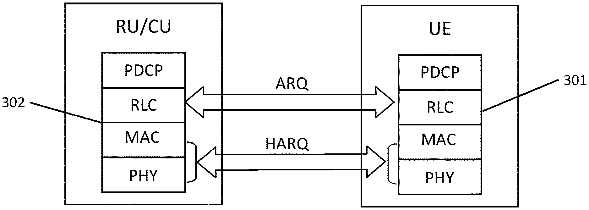
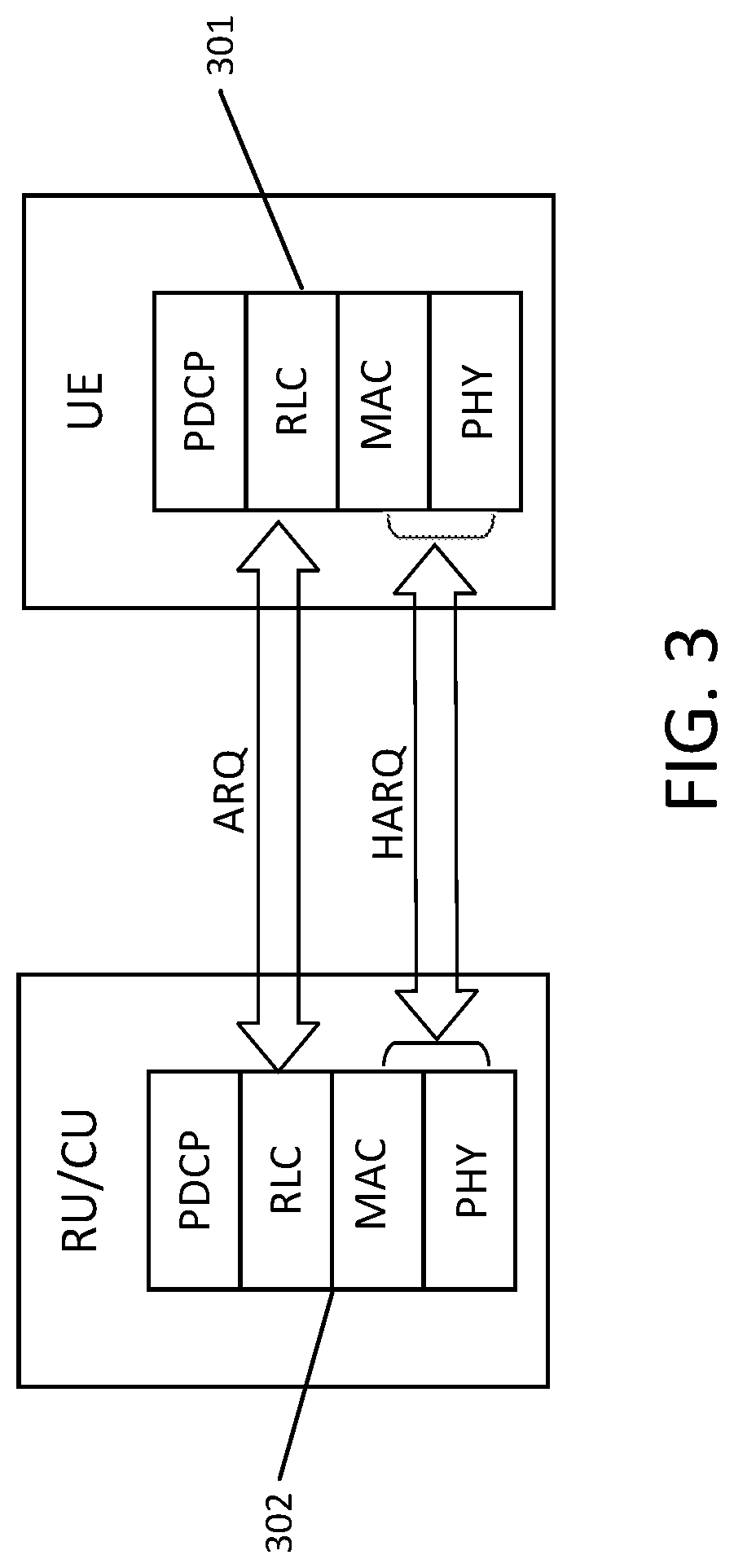
FIG. 3 is a block diagram showing an example of communications between a controller CU/remote unit (RU) and a mobile device.
FIG. 4 is a block diagram showing example communications through different communication layers of a network device.
FIG. 5 is a block diagram showing of communications between a RU/CU and user equipment (UE), such as a mobile device.
FIG. 6 is a block diagram showing communication between media access control (MAC) and radio link control (RLC) layers in an RU/CU and UE, and communications between the RU/CU and the UE.
FIGS. 7 and 8 are block diagrams showing examples of uplink communications between a RU/CU and UE.
FIG. 9 is a block diagram showing example actions performed in a process for relaxing latency constraint in downlink HARQ.
FIG. 10 is a block diagram showing example actions performed in a process for relaxing latency constraint in uplink HARQ.
FIG. 11 is a block diagram showing example actions performed in a process for relaxing latency constraint in uplink HARQ.
Like reference numerals in different figures indicate like elements.
DETAILED DESCRIPTION
The systems and techniques described below are example implementations of features that may be included in a radio access network. The claims made herein are not limited to the example implementations described below.
Referring to FIG. 1, an example radio network 12 is deployed on a site 10 so that one or more mobile operators, such as operator A 14 or operator B 16, can provide mobile network access to one or more instances of user equipment (UE(s)) 18, 20, such as smartphones, at site 10. The radio network 12 of FIG. 1 can be implemented with various air interface technologies. For example, 4G LTE may be used. LTE is a standard developed by 3GPP, a standards organization. The site may be an enterprise or corporate building, a public venue, such as a hotel, hospital, university campus, or even an outdoor area such as a ski area, a stadium, or a densely-populated downtown area or a city.
The radio network 12 includes controllers, each of which is also referred as a controller unit (CU) The CUs may contain one or more processors or other processing devices on which code is executed to perform at least some network and baseband modem functions. The processors can include hardware formed by integrated circuits (ICs) and/or other electrical components, such as system on chips (SoCs). Each CU 22, 24 may contain one or more baseband modem processors or may be configured to perform the functions of one or more baseband modems. In some implementation, one or more of the CUs may be implemented using network function virtualization (NFV) as a virtualized software application running on a virtual machine/hypervisor. The virtual machine/hypervisor may run on a hardware that is shared with other virtualized applications. The hardware may include one or more servers and/or other computing devices. In some implementations, each CU manages one or more of the remote units (RUs) 26a, 26b, 26c, 26d, 26e, 26f, 26g, 26h, 26i ("26a-26i").
The RUs (also called radio points (RPs)) may be controlled by the CUs and may include hardware, such as radio transceivers and SoCs. The RUs 26a-26i may contain RF transceivers to transmit RF signals to and from UEs and to perform RF front-end functions, among other functions. The RUs may have transmit antennas that are integral thereto or that are external and connect to the RUs via antenna cables. In some implementations multiple RUs served by a CU may belong to the same cell. In some implementations based on the LTE standard, multiple RUs may transmit the same Physical Cell ID (PCI). RUs that belong to the same cell may transmit to different UEs in the same time-frequency resource. RUs in the same cell may transmit the same cell-specific reference signals and the same control signals. In some implementations, a CU may serve multiple cells. In some examples, there may be less software functionality running on the RUs than on CUs 22, 24. In some implementations, the RUs are configured to perform no baseband modem functionality. In some implementations, the RUs may perform some baseband modem functionality. For example, in the LTE standard, the RUs may implement Fast Fourier Transform (FFT) and Inverse FFT (IFFT) functions. In some implementations, the RUs may perform additional downlink baseband modem functions. For example, RUs may perform all, or the vast majority of, physical layer (described below) functions. In this regard, transmission of data to the UE is referred to as downlink (DL), and transmission of data from the UE is referred to as uplink (UL).
Baseband modems in the CUs and the RUs may be connected through a network 28. In some implementations, network 28 may be an Ethernet network comprised of one or more Ethernet switches, which may be, arranged in a tree-like configuration. In some implementations, all CUs and RUs at site 10 are connected to each other through network 28. In some implementations, one or more other types of computer networks (wired or wireless) are used in addition to, or instead of, an Ethernet network.
In this regard, the portion of network 28 that connects the RUs to the CUs is called the fronthaul, and the time taken for the transmission of data over the fronthaul is called fronthaul delay or (fronthaul) latency. In this example, CUs 22, 24 are also connected (backhauled) to an operator's core network. The operator's core network may include a security gateway (SeGW) and nodes defined in the LTE standard, such as mobility management entities (MME) 14a, 16a and serving gateways (SGW) 14b, 16b. The backhaul connection to the operator's core network may be implemented, in part, through home eNodeB gateways (HeNB GW) 30, 32.
CUs 22, 24 may also connect to the operator's core network via the Internet or other IP-based packet transport network 33. As used herein, "the Internet" may include other networks. When multiple CUs are present as in the example of FIG. 1, one CU may act as an aggregation point and present a single eNodeB network interface towards one or more nodes in the core network; e.g., a SeGW, a MME, a HeNodeB gateway (GW), and/or a SGW. In some implementations, the CUs may also include MME functionality (not shown) and SGW functionality (not shown). Traffic may therefore flow directly between a UE and a destination node 31 on the Internet or on an internal network (e.g., an IP network) at site 10 without traversing the operator's core network.
Each CU may be associated with a mobile operator so that RUs managed thereby may operate on a spectrum that belongs to that mobile operator. A CU may also be shared between multiple mobile operators. Among other things, the CUs may schedule traffic to/from the UEs by assigning resources for over-the-air transmission. Each CU 22, 24 is also connected to a service manager 40, 42 in the example of FIG. 1, which is typically located in the operator's core network. The service manager is responsible for the configuration, activation and monitoring of the radio network. There may also be a local facility service manager, which can allow local information technology (IT) personnel to install and to maintain the radio network.
In some implementations, each CU 22, 24 performs, for each cell it serves, the functions of a base station, except for certain baseband modem and RF functions that may be performed by the RUs. Generally, a base station, such as a small cell, includes a digital baseband modem unit and a network processing unit. In the example system of FIG. 1, the processing baseband functionality (or "baseband functionality") for a cell is split between the CU and the RUs, with each performing at least some of the baseband functionality.
LTE baseband processing functionality may be implemented on network nodes in hardware and/or software. The baseband processing functions that make up the LTE baseband processing functionality are often described in terms of protocol layers, which include the following. The physical layer carries information from a media access control (MAC) layer over an RF interface. Physical layer functions typically include encoding/decoding, modulation/demodulation, precoding and equalization. Functions of the MAC layer include mapping between logical channels and transport channels, and multiplexing of MAC service data units (SDUs) from one or different logical channels onto transport blocks (TB) to be delivered to the physical layer, fast error correction through HARQ, allocating LTE resources to UEs via real-time scheduling (described below), and priority handling between logical channels of one or more UEs. Functions of the radio link control (RLC) layer (above the MAC layer) typically include transfer of upper layer PDUs, such as concatenation, segmentation and reassembly, and error correction through ARQ. In this regard, HARQ and automatic repeat request (ARQ) are retransmission protocols that support reliable communication between devices. Functions of the packet data convergence control (PDCP) layer (above the RLC layer) include handling (among other things) header compression and decompression of IP (Internet Protocol) data, integrity protection of control plane data, and ciphering and deciphering of user plane data and control plane data. Higher layer LTE protocols include the radio resource control (RRC) control sub-layer.
In some implementations, real-time scheduling includes assigning user data to time and/or frequency LTE resources. Real-time scheduling is based on CSI (channel state information) and other information. In DL scheduling, CSI is supplied by the UE. In the LTE standard, the DL CSI may include a channel quality indicator (CQI), precoding matrix indicator (PMI), and rank indicator (RI), sent by the UE. In UL scheduling, channel state is determined by a CU based on transmissions received from the UEs, including DL CSI. In the LTE standard, channel state may also be determined based on the signals transmitted by the UE, for example, the sounding reference signal (SRS).
Each CU can include one or more baseband modems. The baseband modems may be for performing functions of all layers of baseband functionalities, including the MAC/RLC/PDCP layer processing, and upper layer RRC processing. For example, real-time scheduling and HARQ termination, which are part of the MAC layer, may be performed in the CUs. The CUs may also perform physical layer processing. In addition, the CUs may perform other functions similar to a traditional base station, such as the function of a network processing unit, e.g., processing IP data. In some implementations, the CUs do not perform any RF functions.
In some implementations all physical layer functions are implemented in the RUs, and only the baseband functions of the MAC layer and above are implemented in the CUs. In some implementations, the physical layer functions are split between the CUs and RUs. Uplink control channel receiver functions, such as the physical uplink control channel (PUCCH), physical random access channel (PRACH), and SRS, may be implemented in whole or in part in the RUs, whereas the uplink PUSCH receiver functions may be substantially implemented the CUs. The functional split between the CU and the RU may be different on the downlink and on the uplink. In some implementations, substantially all downlink physical layer functions can be implemented in the RUs and a majority of uplink physical layer functions are implemented in the CUs. In other implementations, all physical layer functions are implemented in the CU.
Radio Network Deployment
Referring to FIG. 2, an example radio network 120 is deployed at a site 122. The example radio network of FIG. 2 may be an implementation of, and include all or some of the structure and function of the radio network shown in FIG. 1. In the example of FIG. 2, one or more controllers (CUs) 124 are installed in a room 126, e.g., a telecom room, locally at site 122. CUs may also be deployed off-site and can serve RUs deployed in multiple sites. RUs 128a-128l are distributed throughout site 122. In some implementations, some RUs are wall-mounted with integrated antennas, some RUs are hidden in one or more closets, and some RUs are installed above ceiling tile and attach to a wall-mount antenna via an external antenna cable.
In some implementations, the RUs 128a-128l connect to the CUs 124 through a switched Ethernet network 130, which includes twisted pair and/or fiber optic cables, and one or more Ethernet switches. Other types of networks may be used in the example of FIG. 2 in addition to, or instead of, switched Ethernet network 130. In some implementations, the Ethernet network 130 is dedicated to the radio network alone. In some implementations, radio network 120 shares Ethernet network 130 with other local area traffic at the site 122. For example, in an enterprise network such other traffic may include local traffic generated by various computers in the enterprise that may be connected to the same Ethernet switches. The radio network traffic can be segregated from other traffic by forming a separate virtual local area network (VLAN). High-priority QoS (quality of service) can be assigned to the VLAN to control latency. In the example shown in FIG. 2, the CUs 124 are connected to a co-located Ethernet switch 132 (e.g., in the same room 126). In some implementations, the connection 134 to switch 132 uses a single 10 Gb/s Ethernet link running over fiber optic or Category 6 twisted pair cable, or multiple 1 Gb/s Ethernet links running over Category 5/6 twisted pair cables.
In a radio network, such as the radio networks illustrated in FIGS. 1 and 2, communication between a UE and an RU can be divided into several distinct groups of related functions or layers. Data to be sent over a network passes through each of the layers, where the data may be divided into packets. Some examples of these layers are described above and include the following: the packet data convergence protocol (PDCP) layer, the radio link control (RLC) layer, the medium access control (MAC) layer, and the physical layer (PHY). FIG. 3 illustrates example hierarchies 301, 302 of layers that are included in CUs, RUs, and UEs such as those of FIGS. 1 and 2.
FIG. 4 illustrates example communication between protocol layers. In a node that is transmitting packets, a packet received by a layer from the layer above is called service data unit (SDU), while the packet provided to a lower layer is the protocol data unit (PDU). In the example of FIG. 4, the PDU includes a unit of data that is specified in a protocol of a given layer and that includes protocol header information and possibly user data of that layer. As illustrated in FIG. 4, the PDU of the PDCP layer 401 becomes the SDU of the RLC layer 402, and the PDU of the RLC layer becomes the SDU of the MAC layer 403. PHY layer 404 is used to carry MAC PDUs, also called transport blocks (TBs). An RLC SDU can be segmented into multiple RLC PDUs or multiple RLC SDUs can be combined into a single RLC PDU using length indicator (LI) fields. A real-time scheduler in the CU may determine an appropriate size of the transport block.
The protocol stack applies to both the DL and the UL. In this context, the RU and the CU are referred to collectively as "RU/CU", since one or both of the RU and CU may implement, or be part of, the communications depicted. Transmission of data from the RU/CU to the UE is the downlink (DL), and transmission of data from the UE to the RU/CU is the uplink (DL). In the DL, the RU/CU is the transmitter and the UE is the receiver. In the UL, the UE is the transmitter and the RU/CU is the receiver. HARQ enables fast retransmissions between the MAC/PHY layers of UE 301 and RU/CU 302.
HARQ and RLC Operation
User experience in LTE may depend on several metrics, including, e.g., data throughput (amount of data packets passing through the network), delay jitter (variation in packet delay), and packet error rate (rate of errors in transmitted data packets). In some communication protocols, such as Transmission Control Protocol (TCP), packet error rate needs to be very low (e.g., 10.sup.-5 or lower). However, aiming for a very low error rate in the first transmission of a TB over-the-air (OTA) may unnecessarily lower the achievable throughput. Therefore, communication protocols such as LTE are designed to aim for a moderately high error rate in a first over-the-air transmission, and then to rely on fast retransmissions to correct any errors. Examples of fast retransmission procedures to accelerate correction of errors are described herein. The retransmission of data includes re-sending data that is, at least in part, identical to the data that was originally transmitted. For example, in the case of HARQ retransmission, the payloads of the original data and the retransmitted data may identical.
In some examples, fast error correction can be achieved using HARQ transmissions in the MAC/PHY layers operating with a target error rate of 10% for a first transmission. To reduce delay jitter, HARQ retransmissions may be relatively fast. In some implementations, this can be achieved using a single-bit feedback channel with target error probability of 10.sup.-4 to 10.sup.-3. Since HARQ feedback is not sufficiently reliable for TCP operation, additional ARQ retransmissions are also supported in the RLC layer. RLC retransmissions correct residual HARQ errors that may be, e.g., due to four consecutive HARQ retransmission errors or errors in the HARQ feedback channel. The RLC protocol, in its acknowledged mode (AM) of operation, uses CRC-protected (cyclic redundancy check--protected) feedback to correct for residual errors in HARQ. RLC AM also provides reordering to correct out-of-sequence reception of RLC PDUs. While HARQ errors can be corrected through retransmission within as little as 8 ms, RLC retransmissions can take 50 ms to 100 ms.
Each UE in a radio network such as those of FIGS. 1 and 2, may have one or more radio bearers, which represent a different traffic type that may need different treatment from the radio network. Radio bearers carry either signaling traffic (Signaling Radio Bearer, or SRB) or data traffic (Data Radio Bearer). In some implementations, each radio bearer has its own PDCP instance, RLC instances and a MAC Layer Logical Channel ID (LCD). In this context, an instance may be implemented in computer-executable code that, when executed, enables communication via a particular layer. Each PDCP instance may be associated with one or two RLC instances (downlink and uplink). Each RLC instance can be configured to operate in AM. A PDCP instance can operate independently from RLC and MAC instances, and can encapsulate IP packets or radio resource control (RRC) messages into PDCP PDUs (which are RLC SDUs). An RLC SDU can be segmented into multiple RLC PDUs or multiple RLC SDUs can be combined into a single RLC PDU using Length Indicator (LI) fields.
In LTE, there is a tight coupling between the RLC and the MAC layers. A real-time scheduler determines the transport block size (TBS) based on the size of UE data waiting in a buffer and available airlink resources. The real-time scheduler may be implemented in a CU. Multiple RLC PDUs, represented as MAC SDUs, can be multiplexed in a single MAC PDU, which forms the TB. Each MAC SDU (RLC PDU) is identified in the MAC PDU header by a MAC SDU header, which includes a 5-bit Logical Channel ID (LCID) to identify the radio bearer (or PDCP instance) that the data belongs to, and a Length Indicator (LI) to identify the length of the MAC SDU. When a TB is not correctly received (e.g., after 4 HARQ retransmissions), all AM RLC PDUs that are carried by the TB are retransmitted by the RLC layer. TBs usually carry complete RLC PDUs but, in an RLC retransmission, the original RLC PDU can be segmented and split across multiple TBs.
A component of the RLC ARQ procedure is a Status Report (SR), which is an example of a status message, generated by the receiver of an RLC instance (e.g., on the DL the RLC receiver in the UE, or on the UL the RLC receiver in the CU). For example, a Status Report may be generated, e.g., by a UE following receipt of RLC PDUs from a CU. Among other things, a Status Report identifies errors in RLC PDUs received by the receiving RLC instance. For example, in some implementations, the Status Report indicates, to the transmitting RLC instance (e.g., the RLC instance that is transmitting RLC PDUs), the sequence numbers (SNs) of PDUs that were not correctly received. In a case of re-segmentation during RLC retransmission, the Status Report may also identify specific segments within an RLC PDU that were not correctly received. The Status Report may also identify the first RLC PDU not yet received, indirectly acknowledging the PDUs up to that PDU as correctly received. In some implementations, the Status Report may also include other information not described herein.
In response to receipt of a Status Report, a transmitting RLC instance may retransmit all or some data previously transmitted, thereby effectively correcting error(s) identified in, or implied by, the Status Report. Status Reports may be sent with relatively high priority and high reliability, in some cases employing cyclic redundancy checks (CRCs) to detect any transmission errors. Transmission of a Status Report from an RLC instance receiver can be triggered, e.g., by one or more of the following: expiration of a t-reordering timer (a configurable parameter), or explicit polling by the RLC instance transmitter. In this regard, when an RLC instance receiver detects a missing RLC PDU, it starts a t-reordering timer, and if the condition is not corrected prior to the expiration of the timer, a Status Report is sent. In order to prevent frequent Status Report transmissions, a configurable t-StatusProhibit timer may be used. This timer is started when a Status Report is sent, and no new Status Report is sent while this timer is still running. The t-reordering timer may be long enough to allow HARQ to complete its retransmissions, such that when a HARQ retransmission delays the arrival of an RLC PDU, a Status Report will not be sent. In some examples, the t-Reordering and t-StatusProhibit timers used in the UE on the downlink can take values in the range [0, 200] ms and [0, 500] ms, respectively. In some implementations, default values for the UE (downlink RLC) are 35 ms and 0 ms, respectively. In some implementations of LTE, an RLC instance transmitter can send up to 512 RLC PDUs without receiving a Status Report indicating correct receipt of the transmitted 512 RLC PDUs.
Downlink
The example features described below may be implemented in, but are not limited to use in, a radio network, such as those shown in FIGS. 1 and 2.
FIG. 5 is a block diagram of example operations in the transmission of data in a downlink using HARQ. In this example, a TB is transmitted (501) from the MAC/PHY layer of RU/CU 500 over the physical downlink shared channel (PDSCH) to the MAC/PHY layer of UE 502 at time t=0 ms. When the UE receives the TB from the RU/CU, it sends (503) an ACK/NAK (acknowledged/not acknowledged) signal 4 ms later over the physical uplink control channel (PUCCH) or over the physical uplink shared channel (PUSCH), depending on whether the UE has been allocated PUSCH resources by the real-time scheduler in the CU. Upon receiving a NAK, the RU/CU can retransmit (504) the TB, at any time at or after 8 ms have elapsed since a first transmission. Retransmissions can be sent on any resource block using any appropriate modulation and coding scheme (MCS).
As shown in FIG. 6, in addition to each MAC layer 614, 615, each RLC layer 616, 610 can also be involved in downlink (DL) HARQ transmissions. The RLC layer 616 and the MAC layer 614 may communicate with each other through cross layer communication. In some implementations, DL HARQ supports a maximum of eight HARQ processes, e.g., for a UE up to eight unacknowledged TB transmissions can exist at any given time. Since DL retransmissions can occur on any TTI, RU/CU 600 sends the HARQ process number to UE 602 explicitly in a Downlink Control Indication (DCI) message sent over Physical downlink control channel (PDCCH) (see 503 of FIG. 5). When using spatial multiplexing, the RU/CU may send two TBs in the same TTI using two spatial layers and receive two separate ACK/NAK bits in response thereto. When a NAK is received for one of the layers, the corresponding TB can be retransmitted on the same layer, together with a new transmission sent on the other layer, using the same HARQ process. Therefore, in some implementations, the RU/CU may identify only one HARQ process number even when spatial multiplexing is in use.
The RU/CU also indicates, to the UE, whether a PDSCH transmission represents new data by toggling a new data indicator (NDI) bit in the DCI. The NDI bit may be configured to allow the UE to work-around HARQ feedback errors. For example, when the UE sends a NAK message, but the NAK message is received as an ACK message by the RU/CU, the RU/CU may send a new TB on the same process with the NDI set as "toggled". Upon correctly receiving the new TB, the UE empties its HARQ soft receive buffer and tries to decode the new TB. The old TB, with the RLC PDUs contained therein, will be lost and will be retransmitted by the RLC instance in AM. Without the NDI bit, the UE may have tried to use the new transmission to decode the old TB. This can lead to further latency. Alternatively, when the UE correctly receives a PDSCH TB, the UE delivers it to the MAC layer instance and sends an ACK to the RU/CU. If the ACK is received as a NAK or a discontinuous transmission (DTX), the RU/CU will retransmit the same TB on the same HARQ process with the NDI set as "not toggled." The UE will recognize the feedback error, ignore the retransmission and simply re-send the ACK message.
As shown in FIG. 6, in DL HARQ, RLC instance 610 in the UE may also contain a t-reordering timer 611 and a t-statusProhibit timer 612. When the t-reordering timer expires, the RLC instance in the UE sends a Status Report to an RLC instance in the RU/CU.
Uplink
The example features described below may be implemented in, but are not limited to use in, a radio network, such as those shown in FIGS. 1 and 2.
Uplink (UL) HARQ processes use a synchronous form of HARQ. FIG. 7 illustrates an example of a UL HARQ process. In the example of FIG. 7, The MAC/PHY layer 614 of a UE 600 transmits 701 a TB in a TTI k (where "k" is an integer representing milliseconds greater than zero) over a PUSCH to the MAC/PHY layer 615 of RU/CU 602. On the UL, the RU/CU sends 703 an ACK/NAK message on the Physical Hybrid-ARQ Indicator Channel (PHICH) in TTI k+4, 4 ms after receiving the PUSCH transmission from the UE on TTI k. In this example, a NAK means the PUSCH transmission in TTI k was received in error. Thereafter, a retransmission is requested on TTI k+8 using the same resource blocks (RBs) and modulation parameters as the transmission on TTI k. In other words, a NAK not only serves as a negative acknowledgment, but also as an uplink resource allocation for the retransmission (non-adaptive retransmission). An ACK does not mean that the PUSCH transmission in a given TTI was correctly received. Upon receiving an ACK, the UE does not immediately clear its HARQ transmit (Tx) buffer, unless the UE receives an accompanying DCI Type-0 message carrying a resource allocation for TTI k+8 with a toggled NDI bit. If the ACK is not accompanied by a DCI Type-0 message, the actual meaning of the ACK can be determined by the UE after the UE receives an uplink allocation for the same HARQ process. For example, if the UE receives an uplink allocation on TTI k+12 for transmission in TTI k+16 with the NDI bit toggled (indicating a new data transmission), the UE can conclude that the ACK received in TTI k+4 really meant a correct reception. Therefore, the UE can clear the HARQ transmit (Tx) buffer for that process. If the NDI bit is not toggled (retransmission), the UE may conclude that the ACK received in TTI k+4 was received in error, and retransmit 705 the TB in TTI k+16. The RB allocation can also occur later, for example in TTI k+20, for transmission over the air in TTI k+24. Accordingly, by sending an uplink allocation in the same TTI as the ACK in TTI k+4, the CU can achieve a relatively fast retransmission time (in this example, 8 ms), (same as in the case of NAK) except in an adaptive manner (e.g., using different resource blocks and/or modulation and coding scheme).
Another aspect of HARQ is the use of a redundancy version (RV). In example versions of LTE HARQ, there are four possible RVs that correspond to different sets of coded data. On both the downlink and the uplink, the RV is explicitly indicated in a resource allocation message by a two-bit index carried in the DCI. When using non-adaptive retransmissions based on a NAK on the uplink, the UE follows a specific fixed sequence {0, 2, 3, 1} of RVs in retransmissions. In adaptive retransmissions, DL or UL, the RV is explicitly indicated. A HARQ receiver can perform soft-combining either using chase combining, which involves combining transmissions of the same RV, or incremental redundancy, which provides combining for different RVs. In turbo coding, there may be situations where chase combining gives better performance than incremental redundancy soft combining.
As illustrated in FIG. 8, in an example, UL HARQ also supports eight processes, but these processes are tied to a specific TTI: transmissions on TTI k belong to HARQ process k (mod 8). The MAC/PHY layers in RU/CU communicate with their respective RLC layer through cross-layer communication. The RLC in the RU/CU has a t-Reordering time and a t-statusProhibit timer. Upon expiration of the t-Reordering timer, the RU/CU can send a Status Report to the RLC layer in the UE. In FIG. 8, scheduler 620 schedules communications to/from the UE, as described herein.
Relaxing of Latency Constraint in Downlink HARQ
The example features described below may be implemented in, but are not limited to use in, a radio network, such as those shown in FIGS. 1 and 2.
On the DL, HARQ latency constraints can be relaxed by delaying data retransmission from the CU when a NAK message is received in response to an initial data transmission. Delaying retransmissions may delay the recovery of lost data. This may have some impact on overall throughput. However, if the latency is relatively small (e.g., on the order of 5-10 milliseconds), the decrease in throughput will be insignificant. Since frequency division duplex (FDD) LTE supports eight HARQ processes, in "normal" LTE HARQ operation, the CU will suspend transmissions to a UE if the CU has eight unacknowledged HARQ processes pending for that UE. For example, if HARQ retransmissions are delayed by 4 ms (sent 12 ms after previous transmission), the percentage of TTIs, on which the UE can be consecutively scheduled, is reduced from 100% to 66%. This is because, after the UE is scheduled in eight consecutive TTIs, no new transmission is scheduled for the next four TTIs. To generalize the example above, when retransmissions are delayed by "p" ms, HARQ suspension will reduce the percentage of TTIs available for scheduling a specific UE by p/(8+p), or 33% for p=4 ms, 50% for p=8 ms, and 67% for p=16 ms. Reductions in available TTIs for a UE does not necessarily imply a reduction in total system throughput. If the remaining TTIs can be filled with data for other UEs, total system throughput may be maintained. In situations where data demand is concentrated in a single UE, suspension of a UE's transmission can cause a reduction in that UE's throughput.
Referring to FIG. 9, in an example implementation 900, in spite of delay in HARQ retransmissions, actions can be taken to reduce the impact of the delay on UE throughput. For example, when the UE 902 has all its eight HARQ processes 920a-920h pending; e.g., no ACK message is yet received for any of the TBs previously sent on eight different HARQ processes, CU 901 can still send 904 a new TB on any of the pending HARQ processes with the new data indicator (NDI) set as "toggled," which indicates that the current TB is a new TB (here, "TB_1"). On receiving TB_1 at UE 902, previously transmitted TB 903 (e.g., TB_0) on the same HARQ process (shown here as "HARQ Process=x") is/are overridden. As a result, the HARQ for TB_0 is effectively turned off. The UE 902, upon receiving 904 TB_1 on a HARQ process for which the UE 902 sent 906 an ACK/NAK, will clear old data (belonging to TB_0) from its HARQ receive soft buffer. As long as the UE 902 is receiving data correctly and sending ACK messages, the UE 902 can continue to receive new TBs in every TTI and can, in some cases, operate at its peak rate. If TB_0 is received 903 by the UE 902 in error, the UE 902 will send 906 a NAK message to the CU. However, if prior to receiving a retransmission of TB_0, the receive soft buffer in the UE where TB_0 is stored is overridden by TB_1, then it is up to the RLC layer to recover the lost data of TB_0 through communication 909a between the RLC layers of the RU/CU 901 and UE 902, as described herein.
Delayed HARQ retransmissions may present a trade-off to the scheduler 920 in the RU/CU 901. For example, if a given UE (e.g., UE_0) is to be scheduled in a TTI and an ACK/NAK message is not yet available for any of the UE's eight pending HARQ processes 920a-920h due to high fronthaul latency or any other reason (e.g., errors in PDSCH or ACK/NAK transmissions), and there are no other UEs with data in buffer waiting to be scheduled, the RU/CU 901 can continue to transmit to the UE by turning off HARQ for one or more of the pending TBs. When the PDSCH RBs in the TTI can be allocated to other UEs with available HARQ processes, the scheduler can, in some examples, skip allocating any RBs to UE_0 without significantly affecting total system throughput. Otherwise, the scheduler 920 can allocate resource blocks (RBs) to UE_0 and accept disabling of HARQ for pending TB(s) on that process. In some cases, the scenario described above, where a UE has all its eight HARQ processes 920a-920h pending, may occur more frequently as the fronthaul latency increases.
When the scheduler 920 determines to allocate PDSCH RBs to a UE_0 on a pending HARQ transmission, resulting in the pending HARQ transmission being overridden, the scheduler 920 can implement one or more of the following operations to accelerate recovery of overridden TB(s). The recovery operations may be implemented in RLC or MAC layer instances on one or more appropriate devices.
In some implementations, the RU/CU 901 may accelerate transmission 909b of the RLC Status Report by a UE 902 by configuring the UE with a t-reordering timer 911 that is less than a default value. After the timer expires, a Status Report is automatically sent from the UE 902 to the RU/CU 901. As described herein, the Status Report identifies data that was correctly received by the UE 902 and data that was not yet correctly received by the UE. For example, the Status Report may identify missing RLC PDUs. For example, missing RLC PDUs can be related to TB_0 sent by MAC layer 914 in the CU that was not successfully received by the MAC layer 915 in the UE. Alternatively, the Status Report may identify what data was received correctly and the sender (e.g., the RU/CU) may determine, from its own records, what data the UE did not correctly receive.
The timer 911 may be configured by sending appropriate configuration messages 909a from the RU/CU 901 to the UE 902. The RU/CU 901 may configure UEs with a t-reordering timer (for example, timer 911) by communicating to processing device(s) on the UEs, and programming those processing devices with appropriate timers. Configuring the timer in this manner may accelerate recovery of lost data via transmission of the configuration message 909a from the RLC layer 916 in the CU and 910 in the UE, by triggering more quickly a Status Report transmission 909b in response to expiration of the t-reordering timer 911.
In some implementations, a MAC instance 914 in the RU/CU 901 receives 906 a delayed NAK message from the UE 902 for an overridden TB, for example TB_0. In response, the MAC instance in the RU/CU 901 may send instructions to all or some RLC instances in the CU (for example, through cross-layer communication 908) for which PDUs were carried in TB_0 to trigger each RLC instance to set a Status Report polling bit in the next RLC PDU sent to the UE. This Status Report polling bit triggers the corresponding RLC instance in the UE 902 to transmit 909b a Status Report immediately. This method may thus accelerate recovery of lost data via the RLC layer by triggering a Status Report transmission from the UE.
In some implementations, instead of waiting for a Status Report from an RLC instance in the UE 902, the RU/CU 901 may itself trigger a retransmission at the RLC instance(s). This method employs a cross-layer interaction between the RLC and MAC/PHY layers. For example, an association may be maintained between MAC PDUs (TBs) and RLC SNs or segments that are carried therein. When a TB is lost, a MAC instance in the RU/CU 901, upon receipt 906 of the delayed NAK, sends a request, for example, through cross layer communication 908, to the RLC instance(s) 916 in the RU/CU 901 instructing the retransmission of the lost RLC PDUs or segments without waiting for a Status Report to arrive from the UE 902. This method may thus accelerate recovery of lost data via the RLC layer by retransmission without requiring a UE Status Report.
In some implementations, upon receiving 906 a delayed NAK for an overridden TB, the MAC layer 914 in the CU 901 may retransmit 950 the same TB (e.g., TB_0) as new HARQ data on any available HARQ process. To do this, the scheduler 920 in the CU may prioritize the overridden TB and assign PDSCH RBs to the overridden TB. The PDSCH data will be indicated using a DCI having an NDI toggled to indicate that the TB is new. In other words, the system prioritizes transmission of the one or more new HARQ transmissions; and assigns PDSCH resource blocks to the one or more new HARQ transmissions, with downlink control information sent to the mobile device including a new data indicator bit set to indicate a new HARQ transmission.
UE 902 therefore receives the resulting transmission, treats this transmission as new transmission, and attempts to decode the new transmission. To increase the likelihood of successful transfer and receipt, the scheduler 920 may not allow this new TB to be overridden again so that HARQ is not disabled a second time. The scheduler 920 may also allocate excess RBs to the UE and apply back-off to the modulation and coding scheme (MCS) of the TB in order to increase the likelihood of successful transfer and receipt.
Retransmitting the TB as new HARQ data (e.g., in response to receiving a delayed NAK for an overridden TB) can be advantageous. For example, retransmitting the TB as a new HARQ data may be relatively easy to implement because, in some implementations, it need not rely upon any cross-layer communication 908 between RLC 916 and MAC 914 layers. In some examples, to increase the reliability of this method, it may be beneficial to increase the value of the RLC t-reordering timer (e.g., to 50 ms). Doing so may reduce the likelihood that the UE will send a Status Report prior to receiving the retransmitted TB as new HARQ data that produces a premature retransmission for RLC PDUs that were carried in the overridden TB before receiving the new transmission of the same TB data.
In some implementations, downlink transmissions may tolerate longer fronthaul delays by using a combination of one or more of: delayed HARQ retransmissions, occasionally reusing HARQ processes while those HARQ processes are still pending thus effectively disabling HARQ for an earlier transmission, and using fast retransmissions in the MAC/PHY or RLC layers to correct for possible errors in earlier transmissions when HARQ is disabled as a result of overriding a pending HARQ process. In some implementations, round-trip fronthaul latencies of 8 ms (or more) can be supported by the processes described herein. However, the implementations described herein are not limited to supporting 8 ms latencies; even higher latencies can be supported.
Relaxing of Latency Constraint in Uplink HARQ
The example features described below may be implemented in, but are not limited to use in, a radio network, such as those shown in FIGS. 1 and 2.
Referring to FIG. 10, in an example implementation 1000, latency constraints in uplink HARQ can be relaxed. On the uplink, increased fronthaul latency may delay receipt of a UE PUSCH transmission at the RU/CU. For a PUSCH transmission received 1003 in a TTI k (where k is an integer representing milliseconds greater than 0) at the RU/CU 1001, the RU/CU 1001 can defer scheduling a HARQ retransmission by forcibly sending 1004 an ACK on the PHICH without a DCI Type 0 in TTI k+4, and can schedule a retransmission 8 ms later in TTI k+12 by sending 1005 a DCI Type 0 for an adaptive retransmission 1006 in TTI k+16. This can accommodate an 8 ms increase in the round-trip fronthaul latency. Such an approach may lead to a reduction of throughput. For example, an 8 ms increase in the round-trip fronthaul latency may lead to a reduction of the percentage of TTIs that UE can be scheduled from 100% to 50%. With such delayed retransmissions, for example, when a UE is scheduled in TTI k, that UE cannot be rescheduled in TTI k+8. Thus, in some cases, when the UE needs to be scheduled in every TTI, its throughput will be reduced by 50%.
When long fronthaul delay causes PUSCH data to arrive 1003 late at the CU 1001, actions can be taken to reduce UE throughput degradation on the uplink. This can be done, for example, if the scheduler 1020 determines that the scheduler is not able to meet the UE's data demand or when the scheduler does not have enough demand from other UEs to utilize available resources. In that case, the scheduler 1020 can optionally override a pending HARQ process by scheduling a new HARQ transmission on the same HARQ process. For example, in FIG. 11, the scheduler 1020 can override a pending HARQ process by allocating resources to the UE 1002 for new data. This can be achieved by sending 1007, in TTI k+4, an ACK on the PHICH together with an uplink resource block (RB) allocation for a new transmission on DCI Type 0. The new PUSCH transmission will occur on TTI k+8 1008. This effectively disables HARQ for the overridden PUSCH TB, which the UE had transmitted 1003 in TTI k. If that PUSCH TB is received 1003 by the CU 1001 in error, a way to recover the PUSCH TB is for the UE 1001 to retransmit the corresponding data at the RLC layer. This process may be used in some cases because there is no mechanism in the LTE MAC layer for the UE to retransmit a TB in the HARQ/MAC layer after the UE is allocated RBs for a new transmission on the same HARQ process.
As illustrated in FIGS. 10 and 11, at the RLC layer, the UE 1002 will retransmit 1009a an RLC PDU upon receiving 1009b a Status Report from the peer RLC instance in the CU 1001 indicating that the RLC PDUs were not correctly received. In this example, assuming no prior errors, the RLC instances 1016 in the CU 1001 may transmit 1009b a Status Report under one of two conditions: a) the RLC 1016 detects the missing RLC PDU after correctly receiving another RLC PDU with a higher sequence number, or b) the RLC 1016 receives a Status Report poll from a peer RLC 1010 instance in UE 1002.
To speed-up RLC retransmission of lost data by a UE, after the PHY/MAC instance 1014 in the CU receives the overridden PUSCH TB in error, the PHY/MAC instance in the CU can send a trigger to all RLC instances in the CU to preemptively transmit Status Report(s) to the UE. Since the PHY/MAC instance in the CU does not know which RLC instances were represented in the lost TB, it will trigger Status Reports in all RLC instances of the UE. Upon receiving the Status Report(s), the RLC instance(s) in the UE will retransmit the lost data. In some implementations, the MAC instance in the CU, upon receiving a negative CRC report for an overridden PUSCH transmission, can send, using cross-layer communications, a trigger to the RLC instance(s) in the CU and request the transmission of Status Report(s) from the CU at the earliest opportunity.
The example implementations of the MAC-RLC interactions described herein can be modified by weaving the Status Report trigger into normal operation of the RLC in the CU. For example, when a MAC instance in the CU detects an unrecoverable HARQ error for an overridden TB, the MAC instance may send cross-layer indications to RLC instances in the CU to configure t-ordering timers to be in an expired state. This expired state will cause all RLC instances of the UE in the CU to send a Status Report upon detecting a missing RLC PDU. Alternatively, the cross-layer indication from the MAC layer can be used in the CU to set a Status Report polling bit on a next RLC PDU(s) received from the UE equal to 1 before an RLC PDU header is processed.
Uplink Subframe Bundling
The example features described below may be implemented in, but are not limited to use in, a radio network, such as those shown in FIGS. 1 and 2.
On the uplink, in a case where a UE is extremely power-limited and may not have enough power to transmit even on a very small number of RBs in each TTI (e.g., one or two RBs), the RBs can be scheduled on multiple consecutive TTIs to meet the data demand. UEs such as this can be starved by any HARQ suspension at the scheduler caused by delayed arrival of PUSCH transmissions at the RU/CU. The CU can therefore configure such UEs to operate in a subframe bundling mode, in which the UE can be allocated resources on multiple consecutive TTIs to send a single TB. In an example implementation of subframe bundling, four redundancy versions of a single transport block can be scheduled at the same time or at about the same time. This can be viewed as a pre-emptive retransmission process, in which the UE transmits four redundancy versions (RVs) without waiting for HARQ feedback. The RV specifies which combination of data is being sent to the UE. In some implementations of subframe bundling, the UE may be allocated at most three RBs per TTI and the modulation order may be limited to QPSK (quadrature phase shift keying). At the highest MCS for QPSK (I_TBS=10), subframe bundling can support a peak rate of 500 bits every four TTIs, or roughly 125 kbps. Subframe bundling allows the UE to transmit at a higher rate (MCS) than otherwise would be possible, and may be useful for VoIP (voice over Internet Protocol) users at or near the edge of a cell. A single HARQ feedback is used for the bundle, which may reduce PHICH and DCI Type-0 overhead. HARQ retransmission delay may be reduced or avoided when the bundle is correctly received.
In some implementations of subframe bundling, the UE may be able to send an entire VoLTE (voice over LTE) packet in four TTIs, and not suffer any blocking due to HARQ suspension. In some implementations of subframe bundling, the CU sends an ACK/NAK 4 ms after the last subframe of the bundle is received from the UE. The CU may be able to decode the bundle before receiving all four subframes, but the UE may still transmit the remaining subframes. In some implementations of subframe bundling, there can be at most four HARQ processes, each occupying four subframes, and the HARQ loop is 16 ms (e.g., retransmission can occur at the earliest 16 ms after the first transmission). This means that, in some implementations, the grant for a retransmission can occur 5 ms after a forcible ACK. For example, when a first subframe bundle transmission occurs on TTIs k through k+3, the forcible ACK is sent in TTI k+7; a retransmission allocation can be sent in TTI k+12; and the retransmission of the bundle can start in TTI k+16. Thus, in this example, the fronthaul latency can be increased by 5 ms without impacting HARQ retransmissions. Subframe bundling can therefore tolerate more latency. If the fronthaul latency is increased further, for example by 8 ms, the retransmission will be delayed until TTI k+32. However, in some implementations, subframe bundling already has built-in retransmissions, and it may be acceptable to disable further retransmissions, provided, e.g., that the MCS is chosen more conservatively for higher reliability. This occurs automatically when UE is allocated RBs for a new transmission in TTI k+16.
Thus, under certain circumstances, the processes described herein may increase fronthaul latency (e.g., by up to 5 ms to 10 ms) and may operate HARQ with delayed retransmissions. In some implementations, for power-limited UEs, subframe bundling may be usable to improve coverage, and HARQ may be operated without any further delays in retransmissions. In some implementations, to prevent the delayed retransmissions from decreasing the percentage of TTIs available for UL transmission, the scheduler in the CU can override a pending TB transmission and initiate a new TB transmission on the same HARQ process. Upon CRC failure for the previous TB, the scheduler can trigger an RLC Status Report to speed up the RLC retransmission by the UE. In some implementations, the processes can tolerate an increase in fronthaul latency (e.g., 8 ms or more), as described herein.
Extension to TD-LTE
The example processes described herein can be implemented in both time division LTE (TD-LTE) systems and frequency division LTE (FD-LTE) system. In TD-LTE, HARQ timing can be different from that in FD-LTE, and may depend on the frame configuration in use. Table 1 below shows normal HARQ timing for different frame configurations of TD-LTE. Also shown in Table 1 are the number of HARQ processes x and y for the DL and UL, indicated as [DL: x, UL: y]. In Table 1, "D" stands for "Downlink", "U" stands for "Uplink", and "S" stands for "Special Subframe".
TABLE-US-00001 TABLE 1 Subframe # 0 1 2 3 4 5 6 7 8 9 0 [DL: 4, UL: 6] D S U U U D S U U U ACK/NAK (in ms) 4 6 4 7 6 4 6 4 7 6 Re-Transmission (in ms) 6 4 6 4 4 6 4 6 4 4 Total Time (in ms) 10 10 10 11 10 10 10 10 11 10 1 [DL: 7, UL: 4] D S U U D D S U U D ACK/NAK (in ms) 7 6 4 6 4 7 6 4 6 4 Re-Transmission (in ms) 4 4 6 4 6 4 4 6 4 6 Total Time (in ms) 11 10 10 10 10 11 10 10 10 10 2 [DL: 10, UL: 2] D S U D D D S U D D ACK/NAK (in ms) 7 6 6 4 8 7 6 6 4 8 Re-Transmission (in ms) 4 4 4 4 4 4 4 4 4 4 Total Time (in ms) 11 10 10 8 12 11 10 10 8 12 3 [DL: 9, UL: 3] D S U U U D D D D D ACK/NAK (in ms) 4 11 6 6 6 7 6 6 5 5 Re-Transmission (in ms) 4 4 4 4 4 4 4 4 4 4 Total Time (in ms) 8 15 10 10 10 11 10 10 9 9 4 [DL: 12, UL: 2] D S U U D D D D D D ACK/NAK (in ms) 12 11 6 6 8 7 7 6 5 4 Re-Transmission (in ms) 4 4 4 4 4 4 4 4 4 4 Total Time (in ms) 16 15 10 10 12 11 11 10 9 8 5 [DL: 15, UL: 1] D S U D D D D D D D ACK/NAK (in ms) 12 11 6 9 8 7 6 5 4 13 Re-Transmission (in ms) 4 4 4 4 4 4 4 4 4 4 Total Time (in ms) 16 15 10 13 12 11 10 9 8 17 6 [DL: 6, UL: 6] D S U U U D S U U D ACK/NAK (in ms) 7 7 4 6 6 7 7 4 7 5 Re-Transmission (in ms) 8 7 6 4 4 7 6 6 7 5 Total Time (in ms) 15 14 10 10 10 14 13 10 14 10
According to the TD-LTE configurations 2-5 of Table 1, a CU/RU has only 4 ms for a DL retransmission, which is the same as in frequency division duplexing (FDD) in FD-LTE systems. The scheduler in a CU can delay retransmission until some other DL subframe. In normal HARQ, this will result in a suspension, when all DL HARQ processes are pending. Generally, the impact of such suspension is lower in TD-LTE than in FD-LTE, because the number of available DL HARQ processes in TD-LTE is higher than in FD-LTE. As in FD-LTE, in TD-LTE a pending PDSCH transmission can be overridden, and HARQ effectively disabled. Data recovery can be triggered using the RLC or MAC layer retransmission methods described herein.
In the TD-LTE configurations 2-5 of Table 1, the CU/RU has 6 ms to send ACK/NAK and DCI Type-0 in response to a PUSCH transmission. This is 2 ms longer than in FD-LTE. If the delays are increased further, in normal HARQ operation, suspension will occur. Since in these common configurations, there are only 1-3 HARQ processes available and the UE may have a bandwidth constraint, suspension of UL transmissions can be problematic. For example, in the extreme example of configuration 5, when a UE is scheduled on subframe 2, the UE should receive a resource allocation in subframe 8 for a retransmission in subframe 12. If the CU/RU is not able to process the PUSCH transmission in time to send the allocation in subframe 8, in normal HARQ, the UE cannot be scheduled again for new data in subframe 12. This will effectively reduce the number of available subframes for UL transmission by 50% from an already low value, but increase the available time at the CU by 10 ms, from 6 ms to 16 ms.
In an example, in subframe 8 the UE can be assigned resources for a new transmission, resulting in HARQ being disabled for the pending TB. The CU can then initiate a data recovery by triggering a Status Report on the DL as described herein.
Random Access (RA) Response
The example features described below may be implemented in, but are not limited to use in, a radio network, such as those shown in FIGS. 1 and 2.
In addition to HARQ, increased fronthaul latency may also impact the timely transmission of the random access (RA) response message by the CU in response to the receipt of a random access preamble. In LTE, once a random access peamble is received from the UE, the eNB needs to transmit a RA response no more than 3+ra-ResponseWindowSize subframes later, where ra-ResponseWindowSize is a cell-specific parameter that can, at most, equal 10 ms in some implementations. In other words, in some implementations, RA response needs to be transmitted over the air no more than 13 subframes after receiving the RA-preamble. Assuming that the RA-response is nominally (zero latency) scheduled in the controller at least 2 ms prior to OTA (over-the-air) and the PRACH detection is available at least 1 ms earlier, the RA response message can be transmitted within the allowed window, as long as the round-trip fronthaul latency is less than 13-2-1=10 ms. In other words, in this example, RA response generation in the CU can tolerate up to 10 ms of round-trip fronthaul latency. Implementations
Although various assumptions are made for the purpose of explanation, the example implementations of the systems and methods described in this disclosure are not limited by these assumptions. Instead, the explanation based on these assumptions can be readily generalized to other situations. For example, the numbers of RUs in each cell, the numbers of antennas for each RU, and the numbers of cells in a network can vary, e.g., based on the network demands.
All or part of the features described herein may, as appropriate, be implemented using a computer program product comprised of instructions that are stored on one or more non-transitory machine-readable storage media, and that are executable on one or more processing devices. All or part of the foregoing may be implemented as an apparatus, method, or system that may include one or more processing devices and memory to store executable instructions to implement functionality.
All or part of the processes described herein and their various modifications (hereinafter referred to as "the processes") can be implemented, at least in part, via a computer program product, e.g., a computer program tangibly embodied in one or more information carriers, e.g., in one or more tangible, non-transitory machine-readable storage media, for execution by, or to control the operation of, data processing apparatus, e.g., a programmable processor, a computer, or multiple computers
A computer program can be written in any form of programming language, including compiled or interpreted languages, and it can be deployed in any form, including as a stand-alone program or as a module, component, subroutine, or other unit suitable for use in a computing environment. A computer program can be deployed to be executed on one computer or on multiple computers at one site or distributed across multiple sites and interconnected by a network.
Actions associated with implementing the processes can be performed by one or more programmable processors executing one or more computer programs to perform the functions of the calibration process. All or part of the processes can be implemented as, special purpose logic circuitry, e.g., an FPGA (field programmable gate array) and/or an ASIC (application-specific integrated circuit).
Processors suitable for the execution of a computer program include, by way of example, both general and special purpose microprocessors, and any one or more processors of any kind of digital computer. Generally, a processor will receive instructions and data from a read-only storage area or a random access storage area or both. Elements of a computer (including a server) include one or more processors for executing instructions and one or more storage area devices for storing instructions and data. Generally, a computer will also include, or be operatively coupled to receive data from, or transfer data to, or both, one or more machine-readable storage media, such as mass storage devices for storing data, e.g., magnetic, magneto-optical disks, or optical disks. Machine-readable storage media suitable for embodying computer program instructions and data include all forms of non-volatile storage area, including by way of example, semiconductor storage area devices, e.g., EPROM, EEPROM, and flash storage area devices; magnetic disks, e.g., internal hard disks or removable disks; magneto-optical disks; and CD-ROM and DVD-ROM disks.
Elements of different implementations described herein may be combined to form other implementations not specifically set forth above. Elements may be left out of the processes, computer programs, etc. described herein without adversely affecting their operation. Furthermore, various separate elements may be combined into one or more individual elements to perform the functions described herein.
Any of the features described herein may be combined, as appropriate, with any of the features described in: (i) U.S. Provisional Application No. 62/009,653 (filed Jun. 9, 2014), which is incorporated herein by reference, (ii) U.S. Provisional Application No. 62/051,212 (filed Sep. 16, 2014), which is incorporated herein by reference, (iii) U.S. patent application Ser. No. 14/734,311 (filed Jun. 9, 2015), which is incorporated herein by reference, (iv) U.S. patent application Ser. No. 13/762,283 (filed Feb. 7, 2013), which is incorporated herein by reference, (v) U.S. patent application Ser. No. 13/762,284 (filed Feb. 7, 2013), which is incorporated herein by reference, and (vi) U.S. patent application Ser. No. 13/762,292 (filed Feb. 7, 2013), which is incorporated herein by reference.
* * * * *
References
D00000
D00001
D00002
D00003
D00004
D00005
D00006
D00007
D00008
D00009
D00010
D00011
XML
uspto.report is an independent third-party trademark research tool that is not affiliated, endorsed, or sponsored by the United States Patent and Trademark Office (USPTO) or any other governmental organization. The information provided by uspto.report is based on publicly available data at the time of writing and is intended for informational purposes only.
While we strive to provide accurate and up-to-date information, we do not guarantee the accuracy, completeness, reliability, or suitability of the information displayed on this site. The use of this site is at your own risk. Any reliance you place on such information is therefore strictly at your own risk.
All official trademark data, including owner information, should be verified by visiting the official USPTO website at www.uspto.gov. This site is not intended to replace professional legal advice and should not be used as a substitute for consulting with a legal professional who is knowledgeable about trademark law.