End effector for a robotic arm
Smith , et al. Sept
U.S. patent number 10,780,588 [Application Number 15/484,929] was granted by the patent office on 2020-09-22 for end effector for a robotic arm. This patent grant is currently assigned to Sarcos LC. The grantee listed for this patent is Sarcos LC. Invention is credited to Glenn Colvin, Jr., Michael Morrison, Wayco Scroggin, Fraser M. Smith.

| United States Patent | 10,780,588 |
| Smith , et al. | September 22, 2020 |
End effector for a robotic arm
Abstract
An end effector for a robotic arm is disclosed. The end effector includes a grasping apparatus having a gripping member and an appendage extending from the gripping member forming a channel between the griping member and the appendage. The channel is configured to receive at least a portion of an article, such as a latch for a container, to be manipulated by the end effector.
| Inventors: | Smith; Fraser M. (Salt Lake City, UT), Morrison; Michael (West Jordan, UT), Colvin, Jr.; Glenn (Park City, UT), Scroggin; Wayco (Sandy, UT) | ||||||||||
|---|---|---|---|---|---|---|---|---|---|---|---|
| Applicant: |
|
||||||||||
| Assignee: | Sarcos LC (Salt Lake City,
UT) |
||||||||||
| Family ID: | 1000005067657 | ||||||||||
| Appl. No.: | 15/484,929 | ||||||||||
| Filed: | April 11, 2017 |
Prior Publication Data
| Document Identifier | Publication Date | |
|---|---|---|
| US 20170217023 A1 | Aug 3, 2017 | |
Related U.S. Patent Documents
| Application Number | Filing Date | Patent Number | Issue Date | ||
|---|---|---|---|---|---|
| 13841006 | Mar 15, 2013 | 9616580 | |||
| 61646743 | May 14, 2012 | ||||
| Current U.S. Class: | 1/1 |
| Current CPC Class: | B25J 15/0475 (20130101); B25J 15/10 (20130101); B25J 15/0066 (20130101); Y10S 901/39 (20130101) |
| Current International Class: | B25J 15/00 (20060101); B25J 15/04 (20060101); B25J 15/10 (20060101) |
| Field of Search: | ;414/680,729,730,732,736,738,739,753.1 ;700/259 ;901/9,31,39,47 |
References Cited [Referenced By]
U.S. Patent Documents
| 1880138 | September 1932 | Franz |
| 2850189 | September 1958 | Leroy |
| 2981198 | April 1961 | Nettel |
| 3171549 | March 1965 | Orloff |
| 3280991 | October 1966 | Melton et al. |
| 3306646 | February 1967 | Flora, Jr. |
| 3358678 | December 1967 | Kulstar |
| 3449008 | June 1969 | Colechia |
| 3449769 | June 1969 | Mizen |
| 3535711 | October 1970 | Fick |
| 3759563 | September 1973 | Kitamura |
| 4046262 | September 1977 | Vykukal et al. |
| 4179233 | December 1979 | Bromell et al. |
| 4200596 | April 1980 | Iiyama et al. |
| 4251791 | February 1981 | Yanagisawa et al. |
| 4398110 | August 1983 | Flinchbaugh et al. |
| 4483407 | November 1984 | Iwamoto et al. |
| 4567417 | January 1986 | Francois et al. |
| 4575297 | March 1986 | Richter |
| 4591944 | May 1986 | Gravel |
| 4603896 | August 1986 | Vasseur et al. |
| 4661032 | April 1987 | Arai |
| 4666357 | May 1987 | Babbi |
| 4723353 | February 1988 | Monforte |
| 4762455 | August 1988 | Coughlan et al. |
| 4768143 | August 1988 | Lane et al. |
| 4821594 | April 1989 | Rosheim et al. |
| 4834443 | May 1989 | Crowder et al. |
| 4853874 | August 1989 | Iwamoto et al. |
| 4883400 | November 1989 | Kuban et al. |
| 4884720 | December 1989 | Whigham et al. |
| 4915437 | April 1990 | Cherry |
| 4921292 | May 1990 | Harwell et al. |
| 4997095 | March 1991 | Jones et al. |
| 5004391 | April 1991 | Burdea |
| 5038089 | August 1991 | Szakaly |
| 5072361 | December 1991 | Davis et al. |
| 5080682 | January 1992 | Schectman |
| 5101472 | March 1992 | Repperger |
| 5105367 | April 1992 | Tsuchihashi et al. |
| 5117814 | June 1992 | Luttrell et al. |
| 5144943 | September 1992 | Luttrell et al. |
| 5172951 | December 1992 | Jacobsen et al. |
| 5230147 | July 1993 | Asaoka et al. |
| 5239246 | August 1993 | Kim |
| 5246216 | September 1993 | Oberst |
| 5280981 | January 1994 | Schulz |
| 5282460 | February 1994 | Boldt |
| 5328224 | July 1994 | Jacobsen et al. |
| 5336982 | August 1994 | Backes |
| 5389849 | February 1995 | Asano et al. |
| 5399951 | March 1995 | Lavallee et al. |
| 5516249 | May 1996 | Brimhall |
| 5577417 | November 1996 | Fournier |
| 5577902 | November 1996 | Todo et al. |
| 5588688 | December 1996 | Jacobsen et al. |
| 5664636 | September 1997 | Ikuma et al. |
| 5704945 | January 1998 | Wagner et al. |
| 5762390 | June 1998 | Gosselin et al. |
| 5784542 | July 1998 | Ohm et al. |
| 5785505 | July 1998 | Price |
| 5797615 | August 1998 | Murray |
| 5845540 | December 1998 | Rosheim |
| 5865770 | February 1999 | Schectman |
| 5898599 | April 1999 | Massie et al. |
| 5912658 | June 1999 | Bergamasco et al. |
| 5949686 | September 1999 | Yoshinada et al. |
| 5957981 | September 1999 | Gramnas |
| 5961476 | October 1999 | Betto et al. |
| 5967580 | October 1999 | Rosheim |
| 5994864 | November 1999 | Inoue et al. |
| 6016385 | January 2000 | Yee et al. |
| 6170162 | January 2001 | Jacobsen et al. |
| 6202013 | March 2001 | Anderson et al. |
| 6272924 | August 2001 | Jansen |
| 6301526 | October 2001 | Kim et al. |
| 6338605 | January 2002 | Halverson et al. |
| 6340065 | January 2002 | Harris |
| 6360166 | March 2002 | Alster |
| 6394731 | May 2002 | Konosu et al. |
| 6425865 | July 2002 | Salcudean et al. |
| 6430473 | August 2002 | Lee et al. |
| 6435794 | August 2002 | Springer |
| 6507163 | January 2003 | Allen |
| 6508058 | January 2003 | Seaverson |
| 6554342 | April 2003 | Burnett |
| 6641371 | November 2003 | Graziani et al. |
| 6659703 | December 2003 | Kirkley |
| 6659939 | December 2003 | Moll et al. |
| 6663154 | December 2003 | Pancheri |
| 6714839 | March 2004 | Salisbury, Jr. et al. |
| 6740125 | May 2004 | Mosler |
| 6855170 | February 2005 | Gramnas |
| 7168748 | January 2007 | Townsend et al. |
| 7369057 | July 2008 | Ye et al. |
| 7396057 | July 2008 | Ye et al. |
| 7405531 | July 2008 | Khatib et al. |
| 7409882 | August 2008 | Massimo et al. |
| 7410338 | August 2008 | Schiele et al. |
| 7509905 | March 2009 | Jacobsen et al. |
| 7628766 | December 2009 | Kazerooni et al. |
| 7783384 | August 2010 | Kraft |
| 7862522 | January 2011 | Barclay et al. |
| 7862524 | January 2011 | Carignan et al. |
| 7883546 | February 2011 | Kazerooni et al. |
| 7947004 | May 2011 | Kazerooni et al. |
| 7965006 | June 2011 | Kang et al. |
| 8024071 | September 2011 | Komatsu et al. |
| 8051764 | November 2011 | Jacobsen et al. |
| 8100451 | January 2012 | Okuda et al. |
| 8132835 | March 2012 | Ban et al. |
| 8151401 | April 2012 | Cheyne |
| 8182010 | May 2012 | Lee et al. |
| 8245728 | August 2012 | Jacobsen et al. |
| 8295975 | October 2012 | Arimatsu et al. |
| 8375982 | February 2013 | Gray, Jr. |
| 8435309 | May 2013 | Gilbert et al. |
| 8452447 | May 2013 | Nixon |
| 8473101 | June 2013 | Summer |
| 8511192 | August 2013 | Bird et al. |
| 8516918 | August 2013 | Jacobsen et al. |
| 8529582 | September 2013 | Devengenzo et al. |
| 8560118 | October 2013 | Greer et al. |
| 8640723 | February 2014 | Jacobsen et al. |
| 8667643 | March 2014 | Simonelli et al. |
| 8672378 | March 2014 | Yamasaki et al. |
| 8747486 | June 2014 | Kawasaki et al. |
| 8794262 | August 2014 | Jacobsen et al. |
| 8821338 | September 2014 | Thorson |
| 8849457 | September 2014 | Jacobsen et al. |
| 8870967 | October 2014 | Herr et al. |
| 8881616 | November 2014 | Dize et al. |
| 8888864 | November 2014 | Iverson et al. |
| 8892258 | November 2014 | Jacobsen et al. |
| 8920517 | December 2014 | Smith et al. |
| 8942846 | January 2015 | Jacobsen et al. |
| 8977388 | March 2015 | Jacobsen et al. |
| 8977398 | March 2015 | Jacobsen et al. |
| 9295604 | March 2016 | Zoss et al. |
| 9314921 | April 2016 | Jacobsen et al. |
| 9329587 | May 2016 | Fudaba et al. |
| 9333097 | May 2016 | Herr et al. |
| 9533411 | January 2017 | Jacobsen et al. |
| 9643323 | May 2017 | Nagatsuka et al. |
| 9727076 | August 2017 | Smith et al. |
| 9789603 | October 2017 | Jacobsen et al. |
| 1002884 | July 2018 | Cheng et al. |
| 1021617 | February 2019 | Gildert et al. |
| 1040667 | September 2019 | Smith et al. |
| 1051258 | December 2019 | Smith |
| 1053354 | January 2020 | Smith et al. |
| 10566914 | February 2020 | Fujita et al. |
| 2001/0033146 | October 2001 | Kato et al. |
| 2001/0043847 | November 2001 | Kramer |
| 2002/0075233 | June 2002 | White et al. |
| 2002/0094919 | July 2002 | Rennex et al. |
| 2003/0005896 | January 2003 | Jacobsen et al. |
| 2003/0146720 | August 2003 | Riwan et al. |
| 2003/0152452 | August 2003 | Hodgson |
| 2003/0223844 | December 2003 | Schiele et al. |
| 2004/0004362 | January 2004 | Love |
| 2004/0037681 | February 2004 | Marcotte |
| 2004/0102723 | May 2004 | Horst |
| 2004/0106881 | June 2004 | McBean et al. |
| 2004/0116836 | June 2004 | Kawai et al. |
| 2004/0246769 | December 2004 | Ido |
| 2004/0250644 | December 2004 | Gosselin et al. |
| 2005/0059908 | March 2005 | Bogert |
| 2005/0099386 | May 2005 | Kukita |
| 2005/0159850 | July 2005 | Melman |
| 2005/0166413 | August 2005 | Crampton |
| 2005/0193451 | September 2005 | Quistgaard et al. |
| 2005/0251110 | November 2005 | Nixon |
| 2006/0052732 | March 2006 | Shimada et al. |
| 2006/0064047 | March 2006 | Shimada et al. |
| 2006/0069449 | March 2006 | Bisbee, III et al. |
| 2006/0130594 | June 2006 | Ikeuchi |
| 2006/0149419 | July 2006 | Ogawa et al. |
| 2006/0184275 | August 2006 | Hosokawa et al. |
| 2006/0197049 | September 2006 | Hamada et al. |
| 2006/0245897 | November 2006 | Hariki et al. |
| 2006/0249315 | November 2006 | Herr et al. |
| 2007/0054777 | March 2007 | Kawai et al. |
| 2007/0105070 | May 2007 | Trawick |
| 2007/0123997 | May 2007 | Herr et al. |
| 2007/0129653 | June 2007 | Sugar et al. |
| 2008/0156363 | July 2008 | Ikeuchi et al. |
| 2008/0269027 | October 2008 | Chen |
| 2008/0271942 | November 2008 | Yamashita et al. |
| 2008/0281468 | November 2008 | Jacobsen et al. |
| 2009/0036815 | February 2009 | Ido |
| 2009/0038258 | February 2009 | Pivac et al. |
| 2009/0039579 | February 2009 | Clifford et al. |
| 2009/0199883 | August 2009 | Hiki |
| 2009/0210093 | August 2009 | Jacobsen et al. |
| 2009/0294238 | December 2009 | Gilmore |
| 2010/0050947 | March 2010 | Kortekaas |
| 2010/0089855 | April 2010 | Kjolseth |
| 2010/0094185 | April 2010 | Amundson et al. |
| 2010/0152630 | June 2010 | Matsuoka et al. |
| 2010/0198402 | August 2010 | Greer et al. |
| 2010/0241242 | September 2010 | Herr et al. |
| 2010/0295497 | November 2010 | Takamatsu |
| 2011/0010012 | January 2011 | Murayama et al. |
| 2011/0040216 | February 2011 | Herr et al. |
| 2011/0046781 | February 2011 | Summer |
| 2011/0066088 | March 2011 | Little et al. |
| 2011/0071677 | March 2011 | Stillman |
| 2011/0219899 | September 2011 | Dize et al. |
| 2011/0264230 | October 2011 | Herr et al. |
| 2012/0000891 | January 2012 | Nakanishi et al. |
| 2012/0060322 | March 2012 | Simonelli et al. |
| 2012/0065902 | March 2012 | Nakajima |
| 2012/0073930 | March 2012 | Lansberry et al. |
| 2012/0137667 | June 2012 | Jacobsen et al. |
| 2012/0179075 | July 2012 | Perry et al. |
| 2012/0191245 | July 2012 | Fudaba et al. |
| 2012/0216671 | August 2012 | Gammon |
| 2012/0237319 | September 2012 | Jacobsen et al. |
| 2012/0259429 | October 2012 | Han et al. |
| 2012/0277901 | November 2012 | Jacobsen et al. |
| 2012/0277911 | November 2012 | Jacobsen et al. |
| 2012/0277915 | November 2012 | Jacobsen et al. |
| 2012/0328395 | December 2012 | Jacobsen et al. |
| 2013/0011220 | January 2013 | Jacobsen et al. |
| 2013/0013108 | January 2013 | Jacobsen et al. |
| 2013/0023803 | January 2013 | Hsu et al. |
| 2013/0033050 | February 2013 | Matsuoka et al. |
| 2013/0057001 | March 2013 | Tsai |
| 2013/0090580 | April 2013 | Hong et al. |
| 2013/0106127 | May 2013 | Lipson et al. |
| 2013/0106128 | May 2013 | Yamasaki et al. |
| 2013/0192406 | August 2013 | Godowski |
| 2013/0226048 | August 2013 | Unluhisarcikili et al. |
| 2013/0253385 | September 2013 | Goffer et al. |
| 2013/0296746 | November 2013 | Herr et al. |
| 2013/0302129 | November 2013 | Smith et al. |
| 2013/0331744 | December 2013 | Kamon |
| 2013/0333368 | December 2013 | Durfee et al. |
| 2014/0100492 | April 2014 | Nagasaka |
| 2014/0190289 | July 2014 | Zhu |
| 2014/0195052 | July 2014 | Tsusaka et al. |
| 2015/0073595 | March 2015 | Fudaba et al. |
| 2015/0073596 | March 2015 | Fudaba et al. |
| 2015/0173929 | June 2015 | Kazerooni et al. |
| 2015/0209214 | July 2015 | Herr et al. |
| 2015/0272749 | October 2015 | Amend, Jr. et al. |
| 2015/0278263 | October 2015 | Bowles et al. |
| 2015/0321342 | November 2015 | Smith et al. |
| 2016/0114482 | April 2016 | Lessing et al. |
| 2016/0153508 | June 2016 | Battlogg |
| 2016/0331572 | November 2016 | Popovic et al. |
| 2016/0332302 | November 2016 | Bingham et al. |
| 2016/0332305 | November 2016 | Gonzalez et al. |
| 2018/0133905 | May 2018 | Smith et al. |
| 2018/0193999 | July 2018 | Jacobsen et al. |
| 2018/0290309 | October 2018 | Becker et al. |
| 2018/0298976 | October 2018 | Battlogg |
| 2019/0176320 | June 2019 | Smith et al. |
| 2019/0184576 | June 2019 | Smith et al. |
| 101214653 | Jul 2008 | CN | |||
| 103610524 | Mar 2014 | CN | |||
| 203495949 | Mar 2014 | CN | |||
| 203752160 | Aug 2014 | CN | |||
| 104843484 | Aug 2015 | CN | |||
| 105818143 | Aug 2016 | CN | |||
| 107471203 | Dec 2017 | CN | |||
| 108081303 | May 2018 | CN | |||
| 102004029513 | Sep 2005 | DE | |||
| 102010029088 | Nov 2011 | DE | |||
| 202013009698 | Nov 2013 | DE | |||
| 102016201540 | Aug 2017 | DE | |||
| 0039578 | Nov 1981 | EP | |||
| 0616275 | Sep 1998 | EP | |||
| 0616275 | Sep 1998 | EP | |||
| 1037264 | Sep 2000 | EP | |||
| 1258324 | Nov 2002 | EP | |||
| 1258324 | Nov 2002 | EP | |||
| 1442846 | Aug 2004 | EP | |||
| 1721593 | Nov 2006 | EP | |||
| 2198810 | Jun 2010 | EP | |||
| 2942162 | Nov 2015 | EP | |||
| 2168548 | Oct 2016 | EP | |||
| 2651220 | Mar 1991 | FR | |||
| 686237 | Jan 1953 | GB | |||
| 2278041 | Nov 1994 | GB | |||
| S34-015764 | Oct 1959 | JP | |||
| S36-005228 | May 1961 | JP | |||
| S44-000603 | Jan 1969 | JP | |||
| S50-009803 | Jan 1975 | JP | |||
| S50-006043 | Mar 1975 | JP | |||
| 52013252 | Feb 1977 | JP | |||
| S52-013252 | Feb 1977 | JP | |||
| S52-134985 | Nov 1977 | JP | |||
| S56-140510 | Nov 1981 | JP | |||
| S56-140510 | Nov 1981 | JP | |||
| S58-113586 | Jul 1983 | JP | |||
| S60-177883 | Nov 1985 | JP | |||
| S62-193784 | Aug 1987 | JP | |||
| S62-193784 | Aug 1987 | JP | |||
| S62-200600 | Sep 1987 | JP | |||
| 01-295772 | Nov 1989 | JP | |||
| H01-295772 | Nov 1989 | JP | |||
| H01-295772 | Nov 1989 | JP | |||
| H02-51083 | Apr 1990 | JP | |||
| H02-51083 | Apr 1990 | JP | |||
| H03-85398 | Aug 1991 | JP | |||
| H03-85398 | Aug 1991 | JP | |||
| H04 44296 | Apr 1992 | JP | |||
| H04-44296 | Apr 1992 | JP | |||
| 5004177 | Jan 1993 | JP | |||
| H05-004177 | Jan 1993 | JP | |||
| H05-023989 | Feb 1993 | JP | |||
| H06-213266 | Aug 1994 | JP | |||
| H07-1366 | Jan 1995 | JP | |||
| H07-001366 | Jan 1995 | JP | |||
| H07-5129 | Feb 1995 | JP | |||
| 7060679 | Mar 1995 | JP | |||
| H07-060679 | Mar 1995 | JP | |||
| H07-112377 | May 1995 | JP | |||
| H07-112377 | May 1995 | JP | |||
| H07-31291 | Jun 1995 | JP | |||
| H07-031291 | Jun 1995 | JP | |||
| H07-246578 | Sep 1995 | JP | |||
| H07-246578 | Sep 1995 | JP | |||
| H08-126984 | May 1996 | JP | |||
| 9-011176 | Jan 1997 | JP | |||
| H09-11176 | Jan 1997 | JP | |||
| H1156931 | Mar 1999 | JP | |||
| 11130279 | May 1999 | JP | |||
| H11-130279 | May 1999 | JP | |||
| 2002-161547 | Jun 2002 | JP | |||
| 2002-161547 | Jun 2002 | JP | |||
| 2003-103480 | Apr 2003 | JP | |||
| 2004/105261 | Apr 2004 | JP | |||
| 2005-118938 | May 2005 | JP | |||
| 2005-237504 | Sep 2005 | JP | |||
| 2005-334999 | Dec 2005 | JP | |||
| 2005-334999 | Dec 2005 | JP | |||
| 2006-016916 | Jan 2006 | JP | |||
| 2006-016916 | Jan 2006 | JP | |||
| 2006007337 | Jan 2006 | JP | |||
| 2006-028953 | Feb 2006 | JP | |||
| 2006-028953 | Feb 2006 | JP | |||
| 2006-051558 | Feb 2006 | JP | |||
| 2006-167223 | Jun 2006 | JP | |||
| 3909770 | Apr 2007 | JP | |||
| 2007-130234 | May 2007 | JP | |||
| 2007-252514 | Oct 2007 | JP | |||
| 2007-307216 | Nov 2007 | JP | |||
| 2008-143449 | Jun 2008 | JP | |||
| 2008-143449 | Jun 2008 | JP | |||
| 2009-023828 | Feb 2009 | JP | |||
| 2009-167673 | Jul 2009 | JP | |||
| 2009-167673 | Jul 2009 | JP | |||
| 2009-178253 | Aug 2009 | JP | |||
| 2009-219650 | Oct 2009 | JP | |||
| 2009-240488 | Oct 2009 | JP | |||
| 2009-268839 | Nov 2009 | JP | |||
| 2010-098130 | Apr 2010 | JP | |||
| 2010-110381 | May 2010 | JP | |||
| 2010-110465 | May 2010 | JP | |||
| 2010-142351 | Jul 2010 | JP | |||
| 2011-193899 | Oct 2011 | JP | |||
| 2012-501739 | Jan 2012 | JP | |||
| 2012-125279 | Jul 2012 | JP | |||
| 2013-022091 | Feb 2013 | JP | |||
| 2013-090693 | May 2013 | JP | |||
| 2013-123786 | Jun 2013 | JP | |||
| 2013-142445 | Jul 2013 | JP | |||
| 5267730 | Aug 2013 | JP | |||
| 2013-248699 | Dec 2013 | JP | |||
| 2014-054273 | Mar 2014 | JP | |||
| 2014-073222 | Apr 2014 | JP | |||
| 2014200853 | Oct 2014 | JP | |||
| 2015112649 | Jun 2015 | JP | |||
| 2015-212010 | Nov 2015 | JP | |||
| 2016-539017 | Dec 2016 | JP | |||
| 2007-0057209 | Jun 2007 | KR | |||
| 2012-0105194 | Sep 2012 | KR | |||
| 10-1219795 | Jan 2013 | KR | |||
| 2013-0001409 | Jan 2013 | KR | |||
| 2013-0045777 | May 2013 | KR | |||
| 2018-0128731 | Dec 2018 | KR | |||
| WO 2003/002309 | Jan 2003 | WO | |||
| WO 2003/081762 | Oct 2003 | WO | |||
| WO 2007/144629 | Dec 2007 | WO | |||
| WO 2007/144629 | Dec 2007 | WO | |||
| WO 2009/143377 | Nov 2009 | WO | |||
| WO 2009/143377 | Nov 2009 | WO | |||
| WO 2010/025409 | Mar 2010 | WO | |||
| WO 2010/027968 | Mar 2010 | WO | |||
| WO 2012/042471 | Apr 2012 | WO | |||
| WO 2017/148499 | Sep 2017 | WO | |||
| WO 2017/159504 | Sep 2017 | WO | |||
| WO 2018/118004 | Jun 2018 | WO | |||
| WO 2018/211869 | Nov 2018 | WO | |||
| WO 2018/215705 | Nov 2018 | WO | |||
Other References
|
Aliens (Movie), Starring Sigourney Weaver, Directed by James Cameron, Written by James Cameron, David Giler, Walter Hill, Dan O'Bannon, Ronald Shuset, Released 1985 by Twentieth Century Fox, Scenes at Playtime 88:26:31-00:26:59 & 00:27:40-00:28:05 & 02:08:25-02:10:39 Non-Patent Literature documentation; Aliens(1986)--IMDb; downloaded Sep. 27, 2014; 4 pages; http://www.imdb.com/title/tt10090605/ cited by applicant . Barras; "Stabilization of a Biped Robot with its arms--A Practical Approach"; May 1, 2010; http://biorob.epfl.ch/files/content/sites/biorob/filed/users/170220/publi- c/Report.pdf; retrieved on Jul. 10, 2013. cited by applicant . Bauman; Utah Firm Markets on Big Gorilla of an Arm; Deseret News; Jan. 27, 1993; 2 pages. cited by applicant . Giant Robot Grabbing Hands Grab All They Can; Jul. 17, 2007; 3 pages ; www.digtalworldtokyo.com/index.php/digital_tokyo/articles/giant_robot_gra- bbing_hands_grab_all_they_can/ cited by applicant . Heavy-Duty Magnetic Base, 300 lb (1334 N) Holding Force, 1/4-20Thread; Newport; http://search.newport.com/?q=*&x2=sku&q2=200; as accessed Apr. 23, 2011; 1 page. cited by applicant . Jacobsen et al; Research Robots for Applications in Artificial Intelligence, Teleoperation and Entertainment; The International Journal of Robotics Research; Apr.-May 2004; pp. 319-330; vol. 23, No. 4-5. cited by applicant . Jacobsen; Science, Robotics, and Superheroes; Presented at University of Utah's Science at Breakfast, Mar. 17, 2010; 16 pages. cited by applicant . Kim et al; A Force Reflected Exoskeleton-Type Masterarm for Human-Robot Interaction; IEEE Transactions on Systems, Man and Cybernetics--Part A: Systems and Humans; Mar. 2005, pp. 198-212; vol. 35, No. 2. cited by applicant . Magnetic Base; www.ask.com/wiki/magnetic_base; 2 pages; page last updated Sep. 12, 2012. cited by applicant . Manipulator Dynamics; Amikabir University of Technology; Computer Engineering and Information Technology Department; Power Point; 44 pages. cited by applicant . Song et al; Kinematics Analysis and Implementation of a Motion-Following Task for a Humanoid Slave Robot Controlled by an Exoskeleton Master Robot; International Journal of Control, Automation and Systems; Dec. 2007; pp. 681-690; vol. 5, No. 6. cited by applicant . Tmsuk, Rescue Robot "T-53" release Control Technologies to Control the Synchronous Operation of the Arm; http://robot.watch.impress.co.jp/cda/news/2007/07/18/564.html; as accessed Sep. 1, 2011; 5 pages. cited by applicant . Yeates; Utah-Built Robot Safeguards the Workplace; http://www.ksl.com?nid=148&sid=17654421&autostart=y; Oct. 13, 2011; 3 pages. cited by applicant . PCT/US2012/035511; filed Apr. 27, 2012; Raytheon Company; International Search Report dated Mar. 4, 2013. cited by applicant . PCT/US2012/035553; filed Apr. 27, 2012; Raytheon Company; International Search report dated Oct. 31, 2012. cited by applicant . PCT/US2012/035570; filed Apr. 27, 2012; Raytheon Company; International Search Report dated Feb. 8, 2013. cited by applicant . Aghili et al., Sensing the torque in a robot's joints, www.memagazine.org/backissues/september98/features/torque/torque.html, The American Society of Mechanical Engineers. cited by applicant . Aliens (Movie), Starring Sigourney Weaver, Directed by James Cameron, Written by James Cameron, David Giler, Walter Hill, Dan O'Bannon, and Ronald Shuset, Released 1985 by Twentienth Century Fox, Scenes at Playtime 88:26:31-00:26:59 & 00:27:40-00:28:05 & 02:08:25-02:10-39, Non Patent Literature documentation; Aliens (1986)--IMDb; downloaded Sep. 27, 2014; 4 pages; http://www.imdb.com/title/ttl00905605/. cited by applicant . Amikabir University of Technology, Manipulator Dynamics (Power Point), Computer Engineering and Information Technology Department, to the best of applicant's knowledge article was available before the application filing date, 44 pages. cited by applicant . Barras, Stabilization of a Biped Robot with its arms--A Practical Approach, http://biorob.epfl.ch/files/content/sites/biorob/filed/users/17- 0220/public/Report.pdf; May 2010, 33 pages, EPFL Biorobotics Laboratory (BioRob), Switzerland. cited by applicant . Bauman, Utah Firm Markets on Big Gorilla of an Arm, Deseret News; Jan. 27, 1993, 2 pages, Deseret News Publishing Company, Salt Lake City, Utah. cited by applicant . Claeyssen et al., Magnetostrictive actuators compared to piezoelectric actuators, Proceedings of SPIE--The International Society for Optical Engineering 4763, Mar. 2003, 6 pages. cited by applicant . Digital World Tokyo, Giant Robot Grabbing Hands Grab All They Can, www.digitalworldtokyo.com/index.php/digital_tokyo/articles/giant_robot_gr- abbing_hands_grab_all_they_can/, Jul. 17, 2007, 3 pages. cited by applicant . Elliot et al., The Biomechanics and Energetics of Human Running using an Elastic Knee Exoskeleton, Jun. 2013, 7 pages, IEEE International Conference on Rehabilitation Robotics, Seattle, Washington. cited by applicant . Elliot et al., Design of a Clutch-Spring Knee Exoskeleton for Running, Journal of Medical Devices, Sep. 2014, 11 pages, vol. 8, The American Society of Mechanical Engineers, New York City, New York. cited by applicant . Endo et al., A quasi-passive model of human leg function in level-ground walking, 2006 IEEE/RSJ International Conference on Intelligent Robots and Systems, Oct. 9-15, 2006, pp. 4935-4939, Institute of Electrical and Electronics Engineers, Piscataway, New Jersey. cited by applicant . Gauthier et al., Magnetic Shape Memory Alloy and Actuator Design, Conference: 5th International Workshop on Microfactories (IWMF'06), Oct. 2006, 5 pages, Besancon, France. cited by applicant . Grabowski et al., Exoskeletons for Running and Hopping Augmentation, Journal of Applied Physiology, http://biomech.media.mit.edu/portfolio_page/load-bearing-exoskeleton-for-- augmentation-of-human-running/, 2009, 4 pages, vol. 107, No. 3, American Physiological Society, United States. cited by applicant . Hauser et al., JammJoint: a Variable Stiffness Device Based on Granular Jamming for Wearable Joint Support, IEEE Robotics and Automation Letters, Apr. 2017, 7 pages, vol. 2, Issue 2, Institute of Electrical and Electronics Engineers, Piscataway, New Jersey. cited by applicant . Huber et al., The selection of mechanical actuators based on performance indices, Oct. 8, 1997, pp. 2185-2205, vol. 453 Issue 1965, The Royal Society, London. cited by applicant . Hunter et al., Fast Reversible NiTi Fibers for Use in Microrobotics, Proceedings. IEEE Micro Electro Mechanical Systems, Jan. 30-Feb. 2, 1991, pp. 166-170, Institute of Electrical and Electronics Engineers, Piscataway, New Jersey. cited by applicant . Industrial Magnetics, Inc., PowerLift.RTM. Magnets; www.magnetics.com/product.asp?ProductID=1; as accessed Nov. 6, 2012, 2 pages; Boyne City, Michigan. cited by applicant . Jacobsen et al., Research Robots for Application in A1, Teleoperation and Entertainment, Proceedings of the International Fluid Power Exposition and Technical Conference, Mar. 24-24, 1992, pp. 1-19, Chicago, Illinois. cited by applicant . Jacobsen et al., Research Robots for Applications in Artificial Intelligence, Teleoperation and Entertainment; The International Journal of Robotics Research; Apr.-May 2004, pp. 319-330, vol. 23, No. 4-5, Sage Publications, Thousand Oaks, California. cited by applicant . Jacobsen, Science, Robotics, and Superheroes, Presented at Department of Science University of Utah Science at Breakfast, Mar. 17, 2010, 16 pages. cited by applicant . Jafari et al., A Novel Actuator with Adjustable Stiffness (AwAS), Oct. 18-22, 2010, 6 pages, IEEE/RSJ International Conference on Intelligent Robots and Systems, Taiwan. cited by applicant . Jansen et al., Exoskeleton for Soldier Enhancement Systems Feasibility Study, Sep. 2000, 44 pages, Oak Ridge National Laboratory, Oak Ridge, Tennessee. cited by applicant . Kazerooni, Berkeley Lower Extremity Exoskeleton (BLEEX), to the best of applicant's knowledge article was available before the application filing date, 3 pages, University of California, Berkeley, Berkeley, California. cited by applicant . Kim, Development of a small 6-axis force/moment sensor for robot's fingers, Measurement Science and Technology, Sep. 30, 2004, 2 pages, Issue 11, Institute of Physics and IOP Publishing Limited. cited by applicant . Kim et al, A Force Reflected Exoskeleton-Type Masterarm for Human-Robot Interaction, IEEE Transactions on Systems, Man and Cybertentics--Part A: Systems and Humans, Mar. 2005, pp. 198-212, vol. 35, No. 2, Institute of Electrical and Electronics Engineers, Piscataway, New Jersey. cited by applicant . Kulick, An Unpowered Exoskeleton Springs Into Action: Researchers Increase Walking Efficiency, http://www.cmu.edu/me/news/archive/2015/collins-clutch/html, Apr. 1, 2015, 2 pages, Carnegie Mellon, University Mechanical Engineering, Pittsburgh, Pennsylvania. cited by applicant . Laliberte et al., Underactuation in Space Robotic Hands, Proceeding of the 6th International Symposium on Artificial Intelligence and Robotics & Automation in Space, Jun. 18-22, 2001, 8 pages, Canadian Space Agency, Canada. cited by applicant . Magnetic Base, www.ask.com/wiki/magnetic_base; page last updated Sep. 12, 2012, 2 pages, retrieved from www.ask.com/wiki/magnetic_base. cited by applicant . Miao et al., Mechanical Design of Hybrid Leg Exoskeleton to Augment Load-Carrying for Walking, International Journal of Advanced Robotic Systems, Mar. 28, 2013, 11 pages, vol. 10, Intech open science open minds, Europe. cited by applicant . Mirfakhrai et al., Polymer artificial muscles, materialstoday, Apr. 2007, pp. 30-38, vol. 10 No. 4, Elsevier, Netherlands. cited by applicant . Mombaur et al., HEiKA-EXO: Optimization-based development and control of an exoskeleton for medical applications, http://typo.iwr.uni-heidelberg.de/groups/orb/research/heika-exo/, Optimization in Robotics & Biomechanics, Oct. 20, 2014, 3 pages, Germany. cited by applicant . Moosavian et al., Dynamics Modeling and Tip-Over Stability of Suspended Wheeled Mobile Robots with Multiple Arms, 2007 IEEE/RSJ International Conference on Intelligent Robots and Systems, Oct. 29-Nov. 2, 2007; pp. 1210-1215, Institute of Electrical and Electronics Engineers, Piscataway, New Jersey. cited by applicant . Newport Corporation, Heavy-Duty Magnetic Base, 300 lb (1334 N) Holding Force, 1/4-20 Thread, http://search.newport.com/?q=*&x2=sku&q2=200, as accessed Apr. 23, 2011, 1 page, Irvine, CA. cited by applicant . Oak Ridge National Laboratory, Foot Force-Torque Sensor Novel Sensor for Measuring Forces and Torques at the Foot, www.ornl.gov, to the best of applicant's knowledge article was available before the application filing date, 1 page, Oak Ridge National Laboratory, Oak Ridge, Tennessee. cited by applicant . Omega, Load Cell Designs, www.omega.com/literature/transactions/volume3/load3.html, Nov. 1, 2005, 3 pages. cited by applicant . Ostling, Wearable Robots, Technology Review, Jul./Aug. 2004, pp. 70-73, Elizabeth Bramson-Boudreau, Cambridge, Massachusetts. cited by applicant . Pan, Improved Design of a Three-degree of Freedom Hip Exoskeleton Based on Biomimetic Parallel Structure, Jul. 2011, 132 pages, University of Ontario Institute of Technology, Canada. cited by applicant . Pelrine et al., Electrostriction of polymer dielectrics with compliant electrodes as a means of actuation, Sensors and Actuators A: Physical, Jan. 1998, pp. 77-85, vol. 64 Issue 1, Elsevier, Netherlands. cited by applicant . Pelrine et al., High-field deformation of elastomeric dielectrics for actuators, Materials Science and Engineering, Nov. 28, 2000, pp. 89-100, vol. 11 Issue 2, Elsevier, Netherlands. cited by applicant . Pelrine et al., Dielectric Elastomer Artificial Muscle Actuators: Toward Biomimetic Motion, Proceedings of SPIE--The International Society for Optical Engineering, Jul. 2002, pp. 126-137, vol. 4695, SPIE, Bellingham, WA. cited by applicant . Pin, Wearable Robotics Presented to New Horizons in Science Briefing, Oct. 2003, 34 pages, Knoxville, Tennessee. cited by applicant . Pratt et al., The RoboKnee: An Exoskeleton for Enhancing Strength and Endurance During Walking, International Conference on Robotics & Automation, Apr. 2004, 6 pages, IEEE, New Orleans, LA. cited by applicant . Robotics Research Group, Degrees of Freedom, www.robotics.utexas.edu/rrg/learn_more/low_ed/dof/, Oct. 25, 2006, 2 pages, University of Texas. cited by applicant . Rouse et al., Clutchable Series-Elastic Actuator: Design of a Robotic Knee Prosthesis for Minimum Energy Consumption, 2013 IEEE 13th International Conference on Rehabilitation Robotics (ICORR), Jun. 24-26, 2013, 6 pages, Institute of Electrical and Electronics Engineers, Piscataway, New Jersey. cited by applicant . Schuler et al., Dextrous Robot Arm, in Proceedings of the 8.sup.thESA Workshop on Advanced Space Technologies for Robotic and Automation `ASTRA 2004` ESTEC, Nov. 2-4, 2004, 8 pages, Noordwijk, The Netherlands. cited by applicant . Searchmap Blog, Scientists Develop Mechanical Spring-Loaded Leg Brace to Improve Walking, http://www.searchmap.eu/blog/scientists-develop-mechanical-spring-loaded-- leg-brace-to-improve-walking/, Apr. 1, 2015, 5 pages, Searchmap Blog. cited by applicant . Seppala, These exoskeleton heels could help stroke victims walk again, http://www.engadget.com/2015/04/02/feet-exoskeletons/, Apr. 2, 2015, Engadget, San Francisco, California. cited by applicant . Shamaei et al., Estimation of Quasi-Stiffness of the Human Knee in the Stance Phase of Walking, Mar. 22, 2013, 10 pages, vol. 8 Issue 3. PLOS One, San Francisco, California. cited by applicant . Siddharth et al., Design and Analysis of a 1-DOF Walking Mechanism, http://siddharthaswaminathan.in/files/WalkingMechanism.pdf, Nov. 2012, 7 pages, India. cited by applicant . Smith et al., Integrated thin-film piezoelectric traveling wave ultrasonic motors, Sensors and Actuators A: Physical, Dec. 2012, pp. 305-311, vol. 188, Elsevier, Netherlands. cited by applicant . Song et al, Kinematics Analysis and Implementation of a Motion-Following Task for a Humanoid Slave Robot Controlled by an Exoskeleton Master Robot, International Journal of Control, Automation and Systems, Dec. 2007, pp. 681-690, vol. 5, No. 6, Korean Institute of Electrical Engineers, South Korea. cited by applicant . Suitx, Phoenix Medical Exoskeleton, https://www.suitx.com/phoenix-medical-exoskeleton, 3 pages, to the best of the applicant's knowledge article was available before the application filing date, US Bionics, Inc., Berkeley, California. cited by applicant . Suleiman, Engineering an affordable exoskeleton, Phys.org, https://phys.org/news/2014-06-exoskeleton,html, Jun. 12, 2014, 5 pages, Science X Network. cited by applicant . Tmsuk, Rescue Robot "T-53" release Control Technologies to Control the Synchronous Operation of the Arm, http://robot.watch.impress.co.jp/cda/news/2007/07/18/564.html, as accessed Sep. 1, 2011 5 pages, Robot Watch website. cited by applicant . Ueda et al., Large Effective-Strain Piezoelectric Actuators Using Nested Cellular Architecture With Exponential Strain Amplification Mechanisms, IEEE/ASME Transactions on Mechatronics, Oct. 2010, pp. 770-782, vol. 15 Issue 5, Institute of Electrical and Electronics Engineers, Piscataway, New Jersey. cited by applicant . Vanderborght et al., Variable impedance actuators: A review, Robotics and Autonomous Systems, Dec. 2013, 14 pages, vol. 61, Issue 12, Elsevier, Netherlands. cited by applicant . Walsh, Biomimetic Design of an Under-Actuated Leg Exoskeleton for Load-Carrying Augmentation, Massachusetts Institute of Technology, Feb. 2006, 97 pages, Massachusetts. cited by applicant . Walsh et al., A Quasi-Passive Leg Exoskeleton for Load-Carrying Augmentation, International Journal of Humanoid Robotics, Mar. 8, 2007, 20 pages, vol. 4, No. 3, World Scientific Publishing Company. cited by applicant . Wang et al., A highly-underactuated robotic hand with force and joint angle sensors, 2011 IEEE/RSJ International Conference on Intelligent Robots and Systems, Sep. 25-30, 2011, 6 pages, Institute of Electrical and Electronics Engineers, Piscataway, New Jersey. cited by applicant . Yeates, Utah-built robot safeguards the workplace, http://www.ksl.com?nid=148&sid=17654421&autostart=y; Oct. 13, 2011, 3 pages, KSL Broadcasting, Salt Lake City, Utah. cited by applicant . Yip et al., High-Performance Robotic Muscles from Conductive Nylon Sewing Thread, 2015 IEEE International Conference on Robotics and Automation (ICRA), May 26-30, 2015, 6 pages, Seattle, Washington. cited by applicant . Zubrycki et al., Novel haptic glove-based interface using jamming principle, Proceedings of the 10.sup.th International Workshop on Robot Motion and Control, Jul. 6-8, 2015, 6 pages, IEEE, Poland. cited by applicant . International Search Report for International Application No. PCT/US2019/068998 dated May 20, 2020, 15 pages. cited by applicant . International Search Report for International Application No. PCT/US2019/069004 dated Apr. 1, 2020, 15 pages. cited by applicant . International Search Report for International Application No. PCT/US2019/069001 dated Apr. 30, 2020, 18 pages. cited by applicant. |
Primary Examiner: Rodriguez; Saul
Assistant Examiner: Tighe; Brendan P
Government Interests
GOVERNMENT LICENSE RIGHTS
This invention was made with government support under H94003-04-D-0006 awarded by the Defense Microelectronics Activity (DMEA). The government has certain rights in the invention.
Parent Case Text
CROSS-REFERENCE TO RELATED APPLICATIONS
This is a divisional application of U.S. application Ser. No. 13/841,006, filed Mar. 15, 2013, entitled "End Effector for a Robotic Arm" which claims the benefit of U.S. Provisional Application Ser. No. 61/646,743, filed May 14, 2012, and entitled, "End Effector for a Robotic Arm," each of which are incorporated by reference in their entirety herein.
Claims
What is claimed is:
1. A method for manipulating an article, the method comprising: positioning an end effector in close proximity to an article to be manipulated, the end effector comprising a grasping apparatus having a gripping member and a first wall, and an appendage extending from the gripping member and having a second wall opposing the first wall, the first and second walls forming an elongated channel between the griping member and the appendage; manipulating the end effector such that at least a portion of the article is caused to be received within the elongated channel, and caused to be captured between the first and second walls to grip the portion of the article received within the elongated channel solely by the first and second walls; and manipulating the end effector to manipulate the portion of the article gripped solely by the first and second walls.
2. The method of claim 1, further comprising manipulating the end effector such that at least a portion of the article is caused to be received within a cut-out formed in the appendage.
3. The method of claim 1, further comprising actuating at least one of a sensor and a light source to assist in manipulating the article.
4. The method of claim 1, further comprising operating at least one additional gripping member.
5. The method of claim 1, further comprising rotating the at least one additional gripping member to a position that minimizes interference during use of the appendage.
6. The method of claim 1, further comprising configuring the at least one additional gripping member with an appendage.
Description
BACKGROUND
Robots can be used to great advantage when automating certain tasks. One area for potential automation is inspecting storage containers. This can reduce the risk to people from potentially hazardous container contents. Most man-handleable storage containers are constructed from stamped sheet metal with latches that have been designed to make them relatively easy for people to open. However, current robotic designs do not exist that make it possible for a robot to be able to easily open such storage containers. Typical two-jaw parallel grippers found on many robots that are equipped with end effectors have not been able to accomplish the container-opening related tasks. As such, in order to be able to facilitate the ability of robotic end effectors to be able to handle, open, inspect and close various containers, either the containers themselves would need to be redesigned to be workable with current end effector designs, or the end effectors themselves would need to be redesigned and configured to achieve such purposes. Redesigning and implementing changes to containers to be workable with current robotic end effector designs would likely result in significant costs.
BRIEF DESCRIPTION OF THE DRAWINGS
Features and advantages of the invention will be apparent from the detailed description which follows, taken in conjunction with the accompanying drawings, which together illustrate, by way of example, features of the invention; and, wherein:
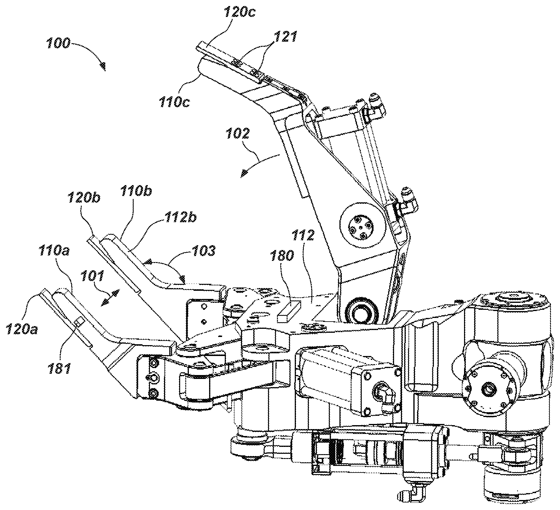
FIG. 1 is an example illustration of an end effector for a robotic arm in accordance with an embodiment of the present invention.
FIG. 2A is an example illustration of a gripping member and an appendage in accordance with an embodiment of the present invention.
FIG. 2B is an example illustration of a gripping member and an appendage in accordance with another embodiment of the present invention.
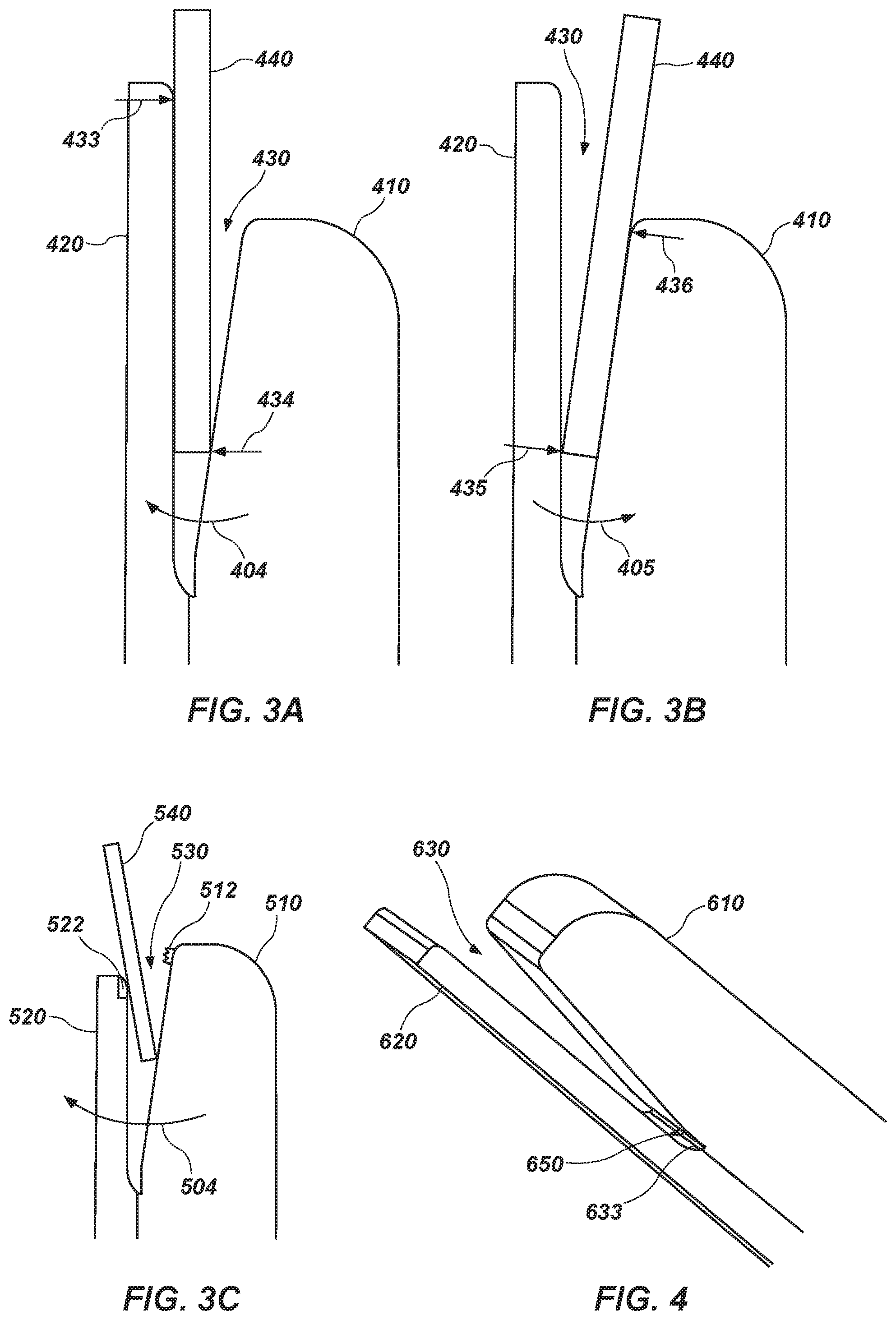
FIGS. 3A and 3B are example illustrations of a channel receiving at least a portion of an article to be manipulated by the end effector, in accordance with an embodiment of the present invention.
FIG. 3C is an example illustration of a channel receiving at least a portion of an article to be manipulated by the end effector, in accordance with another embodiment of the present invention.
FIG. 4 is an example illustration of a sensor associated with an appendage in accordance with an embodiment of the present invention.
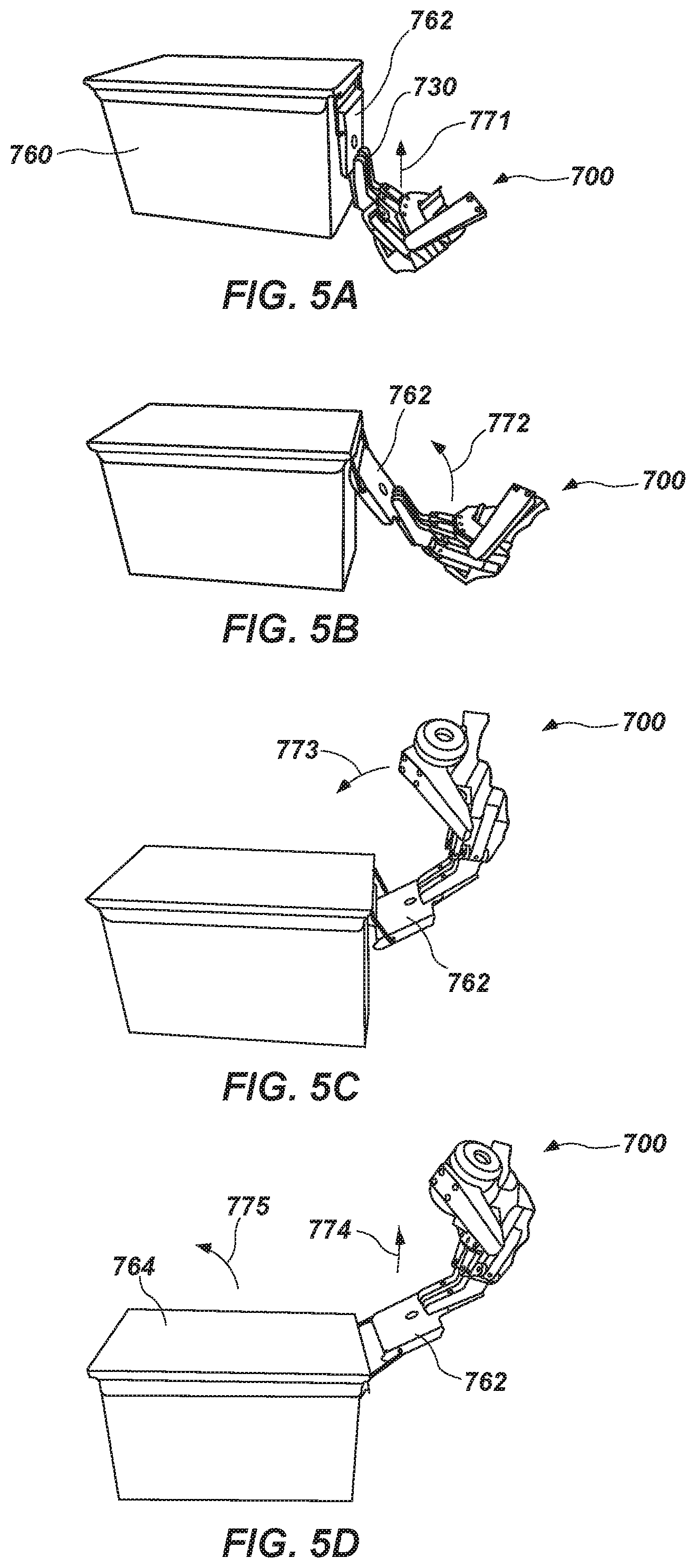
FIGS. 5A-5D are example illustrations of an end effector for a robotic arm manipulating a latch of a storage container in accordance with an embodiment of the present invention.
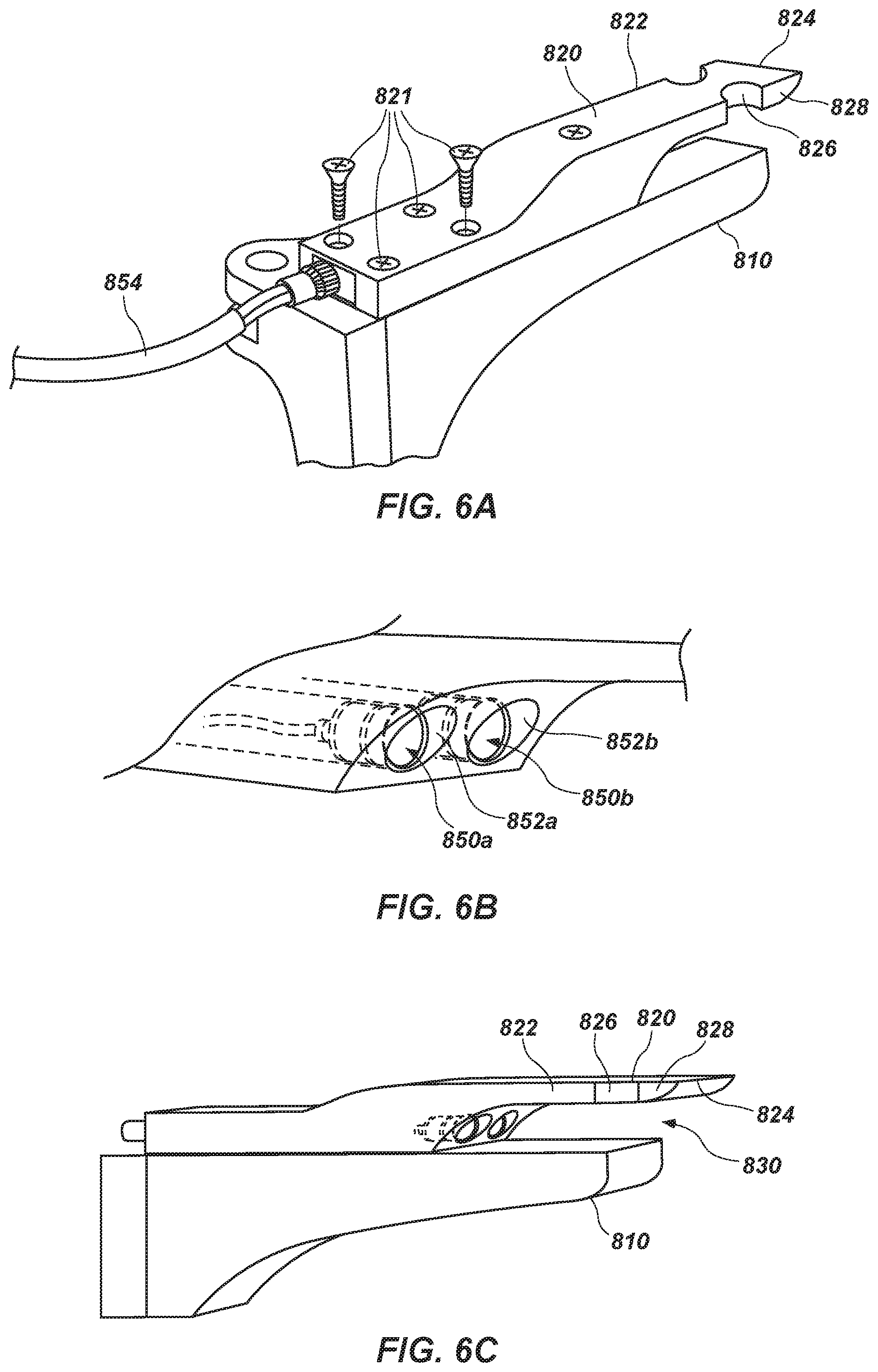
FIGS. 6A-6C are example illustrations of a retrofit appendage in accordance with an embodiment of the present invention.
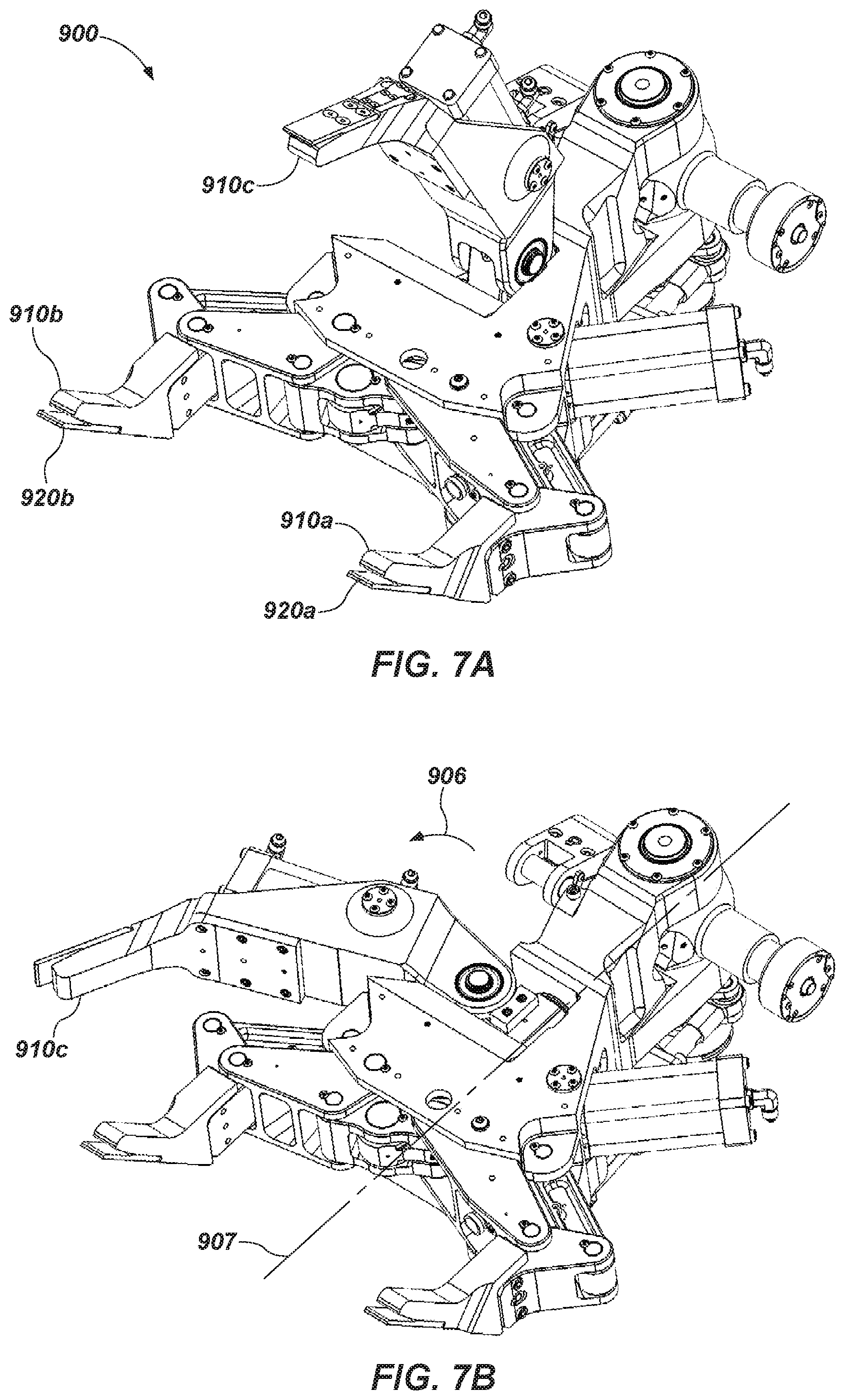
FIGS. 7A and 7B are example illustrations of a gripping member of an end effector that is rotatable to a position that minimizes interference during use of an appendage, in accordance with an embodiment of the present invention.
Reference will now be made to the exemplary embodiments illustrated, and specific language will be used herein to describe the same. It will nevertheless be understood that no limitation of the scope of the invention is thereby intended.
DETAILED DESCRIPTION
As used herein, the term "substantially" refers to the complete or nearly complete extent or degree of an action, characteristic, property, state, structure, item, or result. For example, an object that is "substantially" enclosed would mean that the object is either completely enclosed or nearly completely enclosed. The exact allowable degree of deviation from absolute completeness may in some cases depend on the specific context. However, generally speaking the nearness of completion will be so as to have the same overall result as if absolute and total completion were obtained. The use of "substantially" is equally applicable when used in a negative connotation to refer to the complete or near complete lack of an action, characteristic, property, state, structure, item, or result.
An initial overview of technology embodiments is provided below and then specific exemplary technology embodiments are described in further detail later. This is intended to aid readers in understanding the technology more quickly but is not intended to identify key features or essential features of the technology nor is it intended to limit the scope of the claimed subject matter.
Although typical end effectors having parallel two-jaw grippers can be useful for many applications, such end effectors have proven inadequate to accomplish container-opening and closing related tasks (which may include latching and unlatching tasks), which therefore renders automation of storage container opening and inspection impossible or, at least, prohibitively expensive. Accordingly, an end effector for a robotic arm is disclosed that allows manipulation of a latch for a storage container or similar article. The end effector includes a grasping apparatus having a gripping member and an appendage extending from the gripping member forming a channel between the griping member and the appendage. The channel is configured to receive at least a portion of an article, such as a latch for a storage container, to be manipulated by the end effector.
One embodiment of an end effector 100 for a robotic arm is illustrated in FIG. 1. The end effector 100 can comprise a grasping apparatus having one or more gripping members, such as first and second finger-type gripping members 110a, 110b and a third opposable thumb-type gripping member 110c. One such robotic grasping apparatus is disclosed in U.S. Pat. No. 5,588,688, which is incorporated by reference herein in its entirety. The finger-type gripping members fingers 110a, 110b of the grasping apparatus can be configured to move in direction 101 relative to one another. The thumb-type gripping member 110c can be configured to move in direction 102 to grasp an object. The finger-type and/or thumb-type gripping members can be oriented at an angle 103 to enhance grasping capabilities. In one aspect, the finger-type and/or thumb-type gripping members can be configured such that the angle 103 is adjustable, such as by a rotatable joint.
The end effector 100 can also include one or more appendages, such as appendages 120a, 120b, 120c, extending from one or more of the gripping members. As described in more detail hereinafter, the appendage operate with the gripping member to form a channel or void between the griping member and the appendage, such that the channel comprises walls that interface with an article to be manipulated by the end effector. The channel can be configured to receive at least a portion of an article to be manipulated by the end effector, such as a latch of a storage container. In many containers comprising latches, the latch is typically accessible from one side. The appendage can be positioned on a side or about a surface of the gripping member (e.g., finger and/or thumb-type gripping members) opposite a grasping surface (e.g., see grasping surface 112b of gripping member 110b), similar to a fingernail of a human. Thus, the gripping members of the grasping apparatus can maintain full functionality for grasping objects and, by incorporating an appendage, can also be utilized to manipulate objects that otherwise would have been beyond the capabilities of the end effector. This placement can also provide access to a container latch and, once engaged with the latch, leverage to assist in successfully opening and/or closing the latch. The formation of the channel by the appendage and the gripping member can therefore effectively capture the stamped plate latches present on many storage containers.
In one aspect, an appendage can be an integral or permanent component with a gripping member. In another aspect, as shown in the figure, an appendage can be removably attachable to a gripping member. For example, appendage 120c can be removably coupled to the thumb 110c with fasteners 121. This can provide for interchangeability of the appendage, such as to repair or replace an appendage, to install an appendage of a different configuration, to modify a dimension of the appendage or the formed channel or other attribute or feature, etc. as described herein.
The appendage can comprise a plurality of configurations. For example, in one exemplary embodiment, an appendage can comprise a long, thin structure, and can be made of any suitable material, such as metal, metal alloys, composite materials, plastics, etc. A variety of configurations are contemplated, provided these operate with the gripping member in a suitable manner to provide the functionality discussed herein. Moreover, an appendage can be coupled or associated with any one or more of the gripping members, and a gripping member need not have an appendage.
FIGS. 2A and 2B illustrate different embodiments of channels that can be formed by an appendage and a gripping member. For example, as shown in FIG. 2A, a tapered channel 230 can have walls 237, 238 tapered at an angle 231 to facilitate capturing a latch and to wedge the latch positively into the space provided. Once captured, the end effector has excellent leverage to move the latch to open and/or close the latch. On the other hand, as shown in FIG. 2B, a gap 332 of a channel 330 formed by parallel walls 337, 338 can be uniform along a length of the channel. In any configuration, the channel can be formed and configured to facilitate capture and operation of the latch, a family of similar latches, or a variety of different types of latches.
FIGS. 3A and 3B illustrate an article 440, such as a container latch, in a channel 430 formed by an appendage 420 and a gripping member 410 of an end effector. In FIG. 3A, the end effector causes rotation of the appendage and gripping member in direction 404 such that the gripping member impinges on the article 440 exerting force 434 on the article and appendage 420 impinges on the article exerting force 433 on the article. The forces 433, 434 tend to bind the article in the channel and allow the captured article to be manipulated by the end effector. FIG. 38 illustrates rotation of the end effector in an opposite direction 405. Here, the end effector causes rotation of the appendage and gripping member such that the gripping member impinges on the article 440 exerting force 436 on the article and appendage 420 impinges on the article exerting force 435 on the article.
With reference to FIG. 30, illustrated is another embodiment of a grasping apparatus as part of an end effector, wherein the grasping apparatus is configured to manipulate an article 540 in a channel 530 formed by an appendage 520 and a gripping member 510 of the grasping apparatus of an end effector. In this case, the article 540 is not engaged in the channel to the maximum extent possible. However, as shown in the figure, successful manipulation of the article is still possible. As the end effector is rotated in direction 504, the gripping member and the appendage both impinge on the article sufficient to allow the article to be manipulated by the end effector. This figure illustrates that some of the exemplary appendages and gripping members are contemplated herein as having a suitable configuration (e.g., length dimension) in order to provide a channel with sufficient size, configuration, dimensions to receive an article at various locations within the channel, while still being able to effectively manipulate the article.
Additionally, the appendage and/or gripping member, and the channel formed or defined by these, can include one or more friction enhancing features 522, 512 to improve grip on the article when the article is disposed in the channel. Friction enhancing features can include surface treatments, geometrical features, materials, attachments, etc. configured to enhance friction between the grasping apparatus and the article.
In one aspect of the present disclosure, an appendage can be any suitable length to allow manipulation of the article. For example, as shown in FIGS. 3A and 3B, the appendage 420 can extend a distance beyond the gripping member 410, or beyond the end of the gripping member (again, similar to a fingernail). On the other hand, and in other embodiments, the appendage may not extend beyond the end of the gripping member. For example, the exemplary appendage illustrated in FIG. 3C does not extend beyond the gripping member. Depending on the specific situation, either configuration may prove to be more beneficial in engaging an article.
Referring to FIG. 4, a channel 630 is illustrated with a sensor or light 650 disposed therein. In particular, the channel 630 is formed or defined by an appendage 620 and a gripping member 610. The sensor or light 650 associated with the appendage can be located at a base or bottom 633 of the channel 630, as shown, or can be located at other suitable locations about the appendage 620 and/or gripping member 610, or can be present in plurality, if desired. The sensor and/or light 650 can provide various functions, such as to assist positioning of the channel when receiving the article to be manipulated. In other words, the sensor or light can facilitate alignment and engagement of the channel 630 with an article. Any suitable type of sensor is contemplated for use in accordance with the present disclosure. For example, and not to be limiting in any way, a proximity sensor, a laser rangefinder, radar, LIDAR, a positional sensor, a sonar array, a camera, a microphone, or any other type of sensing instruments, alone or in combination, may be used. Additionally, any type of light may be used, including LEDs, those of different emission spectra, including LASERs, and others. Of course, these are not intended to be limiting in any way as other types of sensors, lights, and equipment may be utilized as known in the art.
The sensor or light 650 can be recessed or disposed in countersunk holes at the bottom of the channel. Recessing the sensor or light can provide protection for the sensor or light from the article in the channel.
In some embodiments, both a light and a sensor can be used together. For example, a light can be used to illuminate the article and a camera can be used to provide a visual of the article. Such a camera can be optimized for the spectra emitted by the light. Information received from the sensor can be used to align and engage the channel with the article. In another example, a LIDAR scanner can enable the end effector to carry out 3-D scans of objects and surroundings to facilitate object recognition and positioning of a given object within a workspace.
Sensor information can be communicated to the operator and/or the robotic device. For example, in one aspect, an operator can use the sensor information to manually guide and maneuver the end effector into engagement with the article. In another aspect, the sensor information can be communicated and processed by the robot in a manner so as to facilitate autonomous maneuver of the end effector into engagement with the article.
In some embodiments of the present disclosure, a sensor and/or light can be associated with or disposed on other components or elements of an end effector. For example, as shown in FIG. 1, a sensor or light 180, 181 can be disposed on a gripping member (finger 110a) and/or a palm 112 of the grasping apparatus. Thus, a finger, thumb, and/or palm of the grasping apparatus can be equipped with camera and illumination assets to further increase the situational awareness provided by the end effector in the workspace. In some embodiments, a finger, thumb, and/or palm of the grasping apparatus can be equipped with assets or equipment, such as barcode or other code readers, and/or RFID tag readers, any of which can be used to interrogate and properly identify the container and associated contents of record. Additionally, other sensors can be associated with a finger, thumb, and/or palm of the grasping apparatus to permit other types of interrogation, such as NDI assets, acoustic detectors, gas detectors, substance-of-interest detectors, vibration sensors, tactile sensors, spectrometers, biohazard detectors, object recognition capabilities, etc.
It is further contemplated that such sensors and equipment can be disposed at any suitable location on the end effector, not just on the grasping apparatus. In the case of an optical reader, for example, the optical reader can be located at any suitable location, such as to provide an unobstructed view of an object to be scanned. The end effector can include any suitable attachment point or feature or interface, such as a pocket, platform, or counter bore, to accommodate and support a sensor, asset, and/or other equipment disposed on the end effector. Those skilled in the art will recognize the many different types of sensors that can be utilized, as well as the several locations that these can be placed about the end effector. Sensors, assets, and/or other equipment can therefore be utilized to open/close a container and/or to inspect the contents of a container once opened.
In a particular aspect of the present disclosure, applicable to facilitating use of the end effector by a human operator in real-time and/or enabling automation of the end effector (such as a container access and inspection process), the sensors, assets, and/or equipment described above can be used to augment situational awareness. For example, a LIDAR or other 3-D scanning system can be used to create 3-D imaging of the workspace and a container within the workspace to provide environment and container-related information to better enable the gripper to correctly mate with the proper portion of the container.
FIGS. 5A-5D illustrate an end effector 700 in use in manipulating a latch 762 of a storage container 760 to unlatch and open the storage container 760. In particular, the end effector 700 can engage the latch 762 by moving in direction 771, such that the appendage is positioned under at least a portion of the latch 762 (with the gripping member positioned over the latch 762), such that a portion of the latch 762 is caused to be at least partially received within the channel 730, as shown in FIG. 5A. Once engaged, the end effector 700 can be caused to move in direction 772 to initiate release of the latch 762, as shown in FIG. 5B, with the portion of the latch 762 being retained in the channel. The end effector 700 can continue movement in direction 773 to complete release and disengagement of the latch 762, as shown in FIG. 5C. Once the latch 762 has been disengaged, the end effector 700 can move in direction 774 and/or 775 to move a cover 764 of the container 760 to open the container 760, as shown in FIG. 5D. It should be recognized that the above-described operation for opening the container 760 can be reversed in order to close the container 760, and latch the latch 762. Thus, as illustrated herein, a single gripping member, or multiple gripping members arranged in parallel, can be used to grab the latch from one side, even if the latch is close to a flat surface, and subsequently the end effector can be operated to manipulate the latch in a manner analogous to the way that the latch would be manipulated by a human.
In addition to the storage container type illustrated in FIGS. 5A-5D, it is contemplated that an end effector in accordance with the present disclosure can be configured to open and/or close a wide variety of container types. For example, the end effector can be configured to open, close, and/or inspect a wide range of ammunition-style and gas can-style storage containers, as well as a paint container, a five gallon container, a 55 gallon drum container, or any other type of container that can be opened and/or closed utilizing an appendage and a channel formed by the appendage. In some cases, such containers have a lid with a lip around a top rim of the container that can be engaged by the appendage. Such containers can hold a wide variety of contents, such as paint, ice melting salt, pickles, chemicals, etc., which can be inspected with appropriate sensors or other equipment disposed on the end effector, as discussed herein. Modifications to the end effector, or end effectors of a somewhat different configuration which are best suited to open a given type of container are contemplated.
With reference to FIGS. 6A-6C, an appendage 820 is illustrated as a retrofit for an existing gripping member 810. The retrofit appendage 820 can be secured to the gripping member 810 with one or more fasteners 821 to form a channel 830. The retrofit appendage 820 can also include one or more sensors or lights 850a, 850b disposed in counter bores 852a, 852b, respectively, as described hereinabove. A cable 854 can be used to transmit power and/or data to/from the sensors or lights. Thus, an appendage can be a stand-alone device that can be added to any existing grasping apparatus/manipulator system to allow the modified grasping apparatus/manipulator system to open and/or close containers.
FIGS. 6A and 6C further illustrate, and the appendage 820 can further comprise, one or more indentations or cut-aways or cut-outs formed along the side or sides 822 of the appendage 820. The one or more cut-outs can comprise any configuration, or can be located anywhere along the appendage 820. In the exemplary embodiment shown, two cut-outs (see for example cut-out 826 and similar cut-out 827) having a semi-circular cross-section are shown formed in the appendage 820 along opposing sides 822 and 823, respectively, of the appendage 820. The cut-out 826 is shown as being positioned near the distal end 824 (unattached or free end) of the appendage 820, and is further shown as being positioned a separation distance away from the end 824, thus providing and defining a lateral edge 828 that intersects with the end 824 and the cut-out 826. Cut-out 827 is similarly positioned and configured relative to the appendage 820. The cut-outs 826 and 827 function to further assist in the opening of various containers or container types. Indeed, the cut-outs 826 and 827 can function to receive and contact a portion of a container to be opened. By providing additional surface area oriented in directions different from the sides 822, 823 and end 824 of the appendage 820, the cut-outs 826 and 827 facilitate the application of forces to and/or against objects to be manipulated (e.g., a container to be opened) that might not otherwise have been available with an appendage devoid of such cut-outs. With the presence of one or more cut-outs, the end effector is provided with additional manipulation capabilities.
As will be recognized by those skilled in the art, the cut-outs 826 and 827 formed in the appendage 820 are not intended to be limiting in any way. Indeed, those skilled in the art will recognize that the appendage can comprise any number of indentations or cut-outs, and that these can comprise any desirable or needed configuration. In addition, those skilled in the art will recognize that one or more cut-outs, similar to those shown in FIGS. 6A and 6C, can be formed in any of the exemplary appendages of any of the exemplary end effectors discussed herein. In other words, those skilled in the art will recognize that any of the exemplary end effectors, with their associated appendage(s), as discussed herein, can comprise one or more indentations or cut-outs similar to those described above and shown in FIGS. 6A and 6C.
FIGS. 7A and 7B illustrate a grasping apparatus of an end effector 900 with an appendage in the form of a thumb 910c that is movable to minimize interference during use of one or more other appendages 920a, 920b. For example, the end effector 900 permits rotation of the thumb 910c in direction 906 about axis 907. Such movement can bring the thumb 910c out of the position opposite the two-jaw gripper (having appendages in the form of fingers 910a, 910b) to a position beside the two-jaw gripper. This can provide space for the appendages 920a, 920b to be used alone and without mechanical interference with the thumb 910c when manipulating an article, such as opening a container. When operations utilizing the appendages are complete, the thumb 910c can be rotated back into position opposite the two-jaw gripper for full grasping functionality of the end effector with the fingers 910a, 910b and the thumb 910c.
It is to be understood that the embodiments of the invention disclosed are not limited to the particular structures, process steps, or materials disclosed herein, but are extended to equivalents thereof as would be recognized by those ordinarily skilled in the relevant arts. It should also be understood that terminology employed herein is used for the purpose of describing particular embodiments only and is not intended to be limiting.
Reference throughout this specification to "one embodiment" or "an embodiment" means that a particular feature, structure, or characteristic described in connection with the embodiment is included in at least one embodiment of the present invention. Thus, appearances of the phrases "in one embodiment" or "in an embodiment" in various places throughout this specification are not necessarily all referring to the same embodiment.
As used herein, a plurality of items, structural elements, compositional elements, and/or materials may be presented in a common list for convenience. However, these lists should be construed as though each member of the list is individually identified as a separate and unique member. Thus, no individual member of such list should be construed as a de facto equivalent of any other member of the same list solely based on their presentation in a common group without indications to the contrary. In addition, various embodiments and example of the present invention may be referred to herein along with alternatives for the various components thereof. It is understood that such embodiments, examples, and alternatives are not to be construed as de facto equivalents of one another, but are to be considered as separate and autonomous representations of the present invention.
Furthermore, the described features, structures, or characteristics may be combined in any suitable manner in one or more embodiments. In the following description, numerous specific details are provided, such as examples of lengths, widths, shapes, etc., to provide a thorough understanding of embodiments of the invention. One skilled in the relevant art will recognize, however, that the invention can be practiced without one or more of the specific details, or with other methods, components, materials, etc. In other instances, well-known structures, materials, or operations are not shown or described in detail to avoid obscuring aspects of the invention.
While the foregoing examples are illustrative of the principles of the present invention in one or more particular applications, it will be apparent to those of ordinary skill in the art that numerous modifications in form, usage and details of implementation can be made without the exercise of inventive faculty, and without departing from the principles and concepts of the invention. Accordingly, it is not intended that the invention be limited, except as by the claims set forth below.
* * * * *
References
-
imdb.com/title/tt10090605
-
biorob.epfl.ch/files/content/sites/biorob/filed/users/170220/public/Report.pdf
-
digtalworldtokyo.com/index.php/digital_tokyo/articles/giant_robot_grabbing_hands_grab_all_they_can
-
search.newport.com/?q=*&x2=sku&q2=200
-
ask.com/wiki/magnetic_base
-
robot.watch.impress.co.jp/cda/news/2007/07/18/564.html
-
ksl.com?nid=148&sid=17654421&autostart=y
-
memagazine.org/backissues/september98/features/torque/torque.html
-
-
digitalworldtokyo.com/index.php/digital_tokyo/articles/giant_robot_grabbing_hands_grab_all_they_can
-
biomech.media.mit.edu/portfolio_page/load-bearing-exoskeleton-for-augmentation-of-human-running
-
magnetics.com/product.asp?ProductID=1
-
cmu.edu/me/news/archive/2015/collins-clutch/html
-
typo.iwr.uni-heidelberg.de/groups/orb/research/heika-exo
-
ornl.gov
-
omega.com/literature/transactions/volume3/load3.html
-
robotics.utexas.edu/rrg/learn_more/low_ed/dof
-
searchmap.eu/blog/scientists-develop-mechanical-spring-loaded-leg-brace-to-improve-walking
-
engadget.com/2015/04/02/feet-exoskeletons
-
siddharthaswaminathan.in/files/WalkingMechanism.pdf
-
suitx.com/phoenix-medical-exoskeleton
-
phys.org/news/2014-06-exoskeleton
D00000
D00001
D00002
D00003
D00004
D00005
XML
uspto.report is an independent third-party trademark research tool that is not affiliated, endorsed, or sponsored by the United States Patent and Trademark Office (USPTO) or any other governmental organization. The information provided by uspto.report is based on publicly available data at the time of writing and is intended for informational purposes only.
While we strive to provide accurate and up-to-date information, we do not guarantee the accuracy, completeness, reliability, or suitability of the information displayed on this site. The use of this site is at your own risk. Any reliance you place on such information is therefore strictly at your own risk.
All official trademark data, including owner information, should be verified by visiting the official USPTO website at www.uspto.gov. This site is not intended to replace professional legal advice and should not be used as a substitute for consulting with a legal professional who is knowledgeable about trademark law.