Systems and methods facilitating reprocessing of surgical instruments
Twomey , et al. Sept
U.S. patent number 10,780,544 [Application Number 15/960,849] was granted by the patent office on 2020-09-22 for systems and methods facilitating reprocessing of surgical instruments. This patent grant is currently assigned to Covidien LP. The grantee listed for this patent is COVIDIEN LP. Invention is credited to James D. Allen, IV, John R. Twomey.


| United States Patent | 10,780,544 |
| Twomey , et al. | September 22, 2020 |
Systems and methods facilitating reprocessing of surgical instruments
Abstract
A method of sharpening a cutting edge of a knife of a surgical instrument includes manipulating an end effector assembly of a surgical instrument such that first and second jaw members of the end effector assembly are disposed in a spaced-apart position, retaining the first and second jaw members in the spaced-apart position, advancing a knife of the surgical instrument to an extended position wherein the knife extends between the first and second jaw members, retaining the knife in the extended position, and sharpening a cutting edge of the knife.
| Inventors: | Twomey; John R. (Longmont, CO), Allen, IV; James D. (Broomfield, CO) | ||||||||||
|---|---|---|---|---|---|---|---|---|---|---|---|
| Applicant: |
|
||||||||||
| Assignee: | Covidien LP (Mansfield,
MA) |
||||||||||
| Family ID: | 1000005067614 | ||||||||||
| Appl. No.: | 15/960,849 | ||||||||||
| Filed: | April 24, 2018 |
Prior Publication Data
| Document Identifier | Publication Date | |
|---|---|---|
| US 20190321930 A1 | Oct 24, 2019 | |
| Current U.S. Class: | 1/1 |
| Current CPC Class: | B24B 3/361 (20130101); A61B 90/70 (20160201); A61B 17/32 (20130101); B08B 3/08 (20130101); A61B 18/1445 (20130101); A61B 2017/00526 (20130101) |
| Current International Class: | B24B 3/36 (20060101); A61B 17/32 (20060101); A61B 90/70 (20160101); B08B 3/08 (20060101); A61B 18/14 (20060101); A61B 17/00 (20060101) |
| Field of Search: | ;451/45 |
References Cited [Referenced By]
U.S. Patent Documents
| D249549 | September 1978 | Pike |
| D263020 | February 1982 | Rau, III |
| D295893 | May 1988 | Sharkany et al. |
| D295894 | May 1988 | Sharkany et al. |
| 4763669 | August 1988 | Jaeger |
| D298353 | November 1988 | Manno |
| D299413 | January 1989 | DeCarolis |
| 5258001 | November 1993 | Corman |
| D343453 | January 1994 | Noda |
| D348930 | July 1994 | Olson |
| D349341 | August 1994 | Lichtman et al. |
| 5344424 | September 1994 | Roberts et al. |
| D354564 | January 1995 | Medema |
| D358887 | May 1995 | Feinberg |
| 5487693 | January 1996 | Prusaitis |
| 5540685 | July 1996 | Parins et al. |
| 5611808 | March 1997 | Hossain et al. |
| D384413 | September 1997 | Zlock et al. |
| H1745 | August 1998 | Paraschac |
| 5797938 | August 1998 | Paraschac |
| 5797941 | August 1998 | Schulze |
| D402028 | December 1998 | Grimm et al. |
| D408018 | April 1999 | McNaughton |
| 5913874 | June 1999 | Berns et al. |
| 5960544 | October 1999 | Beyers |
| D416089 | November 1999 | Barton et al. |
| D424694 | May 2000 | Tetzlaff et al. |
| D425201 | May 2000 | Tetzlaff et al. |
| H1904 | October 2000 | Yates et al. |
| D449886 | October 2001 | Tetzlaff et al. |
| D453923 | February 2002 | Olson |
| D454951 | March 2002 | Bon |
| D457958 | May 2002 | Dycus et al. |
| D457959 | May 2002 | Tetzlaff et al. |
| H2037 | July 2002 | Yates et al. |
| D465281 | November 2002 | Lang |
| D466209 | November 2002 | Bon |
| D493888 | August 2004 | Reschke |
| D496997 | October 2004 | Dycus et al. |
| D499181 | November 2004 | Dycus et al. |
| D502994 | March 2005 | Blake, III |
| D509297 | September 2005 | Wells |
| D525361 | July 2006 | Hushka |
| D531311 | October 2006 | Guerra et al. |
| D533274 | December 2006 | Visconti et al. |
| D533942 | December 2006 | Kerr et al. |
| D535027 | January 2007 | James et al. |
| D538932 | March 2007 | Malik |
| 7195631 | March 2007 | Dumbauld |
| D541418 | April 2007 | Schechter et al. |
| D541611 | May 2007 | Aglassinger |
| D541938 | May 2007 | Kerr et al. |
| D545432 | June 2007 | Watanabe |
| D547154 | July 2007 | Lee |
| D564662 | March 2008 | Moses et al. |
| D567943 | April 2008 | Moses et al. |
| D575395 | August 2008 | Hushka |
| D575401 | August 2008 | Hixson et al. |
| D582038 | December 2008 | Swoyer et al. |
| D617900 | June 2010 | Kingsley et al. |
| D617901 | June 2010 | Unger et al. |
| D617902 | June 2010 | Twomey et al. |
| D617903 | June 2010 | Unger et al. |
| D618798 | June 2010 | Olson et al. |
| D621503 | August 2010 | Otten et al. |
| D627462 | November 2010 | Kingsley |
| D628289 | November 2010 | Romero |
| D628290 | November 2010 | Romero |
| D630324 | January 2011 | Reschke |
| 8020743 | September 2011 | Shelton, IV |
| D649249 | November 2011 | Guerra |
| D649643 | November 2011 | Allen, IV et al. |
| 8074859 | December 2011 | Kostrzewski |
| 8257352 | September 2012 | Lawes |
| 8366709 | February 2013 | Schechter et al. |
| 8425504 | April 2013 | Orton et al. |
| 8469716 | June 2013 | Fedotov et al. |
| 8568408 | October 2013 | Townsend et al. |
| 8591510 | November 2013 | Allen, IV et al. |
| 8628557 | January 2014 | Collings et al. |
| 8663222 | March 2014 | Anderson et al. |
| 8679098 | March 2014 | Hart |
| 8685009 | April 2014 | Chernov, et al. |
| 8685021 | April 2014 | Chernov et al. |
| 8685056 | April 2014 | Evans et al. |
| 8702737 | April 2014 | Chojin et al. |
| 8702749 | April 2014 | Twomey |
| 8745840 | June 2014 | Hempstead et al. |
| 8747434 | June 2014 | Larson et al. |
| 8756785 | June 2014 | Allen, IV et al. |
| 8784418 | July 2014 | Romero |
| 8840639 | September 2014 | Gerhardt, Jr. et al. |
| 8845636 | September 2014 | Allen, IV et al. |
| 8852185 | October 2014 | Twomey |
| 8852228 | October 2014 | Nau, Jr. |
| 8864753 | October 2014 | Nau, Jr. et al. |
| 8864795 | October 2014 | Kerr et al. |
| 8887373 | November 2014 | Brandt et al. |
| 8888771 | November 2014 | Twomey |
| 8898888 | December 2014 | Brandt et al. |
| 8900232 | December 2014 | Ourada |
| 8906018 | December 2014 | Rooks et al. |
| 9585714 | March 2017 | Livneh |
| 2008/0280540 | November 2008 | Johnson |
| 2010/0179545 | July 2010 | Twomey et al. |
| 2012/0083785 | April 2012 | Roy et al. |
| 2012/0083786 | April 2012 | Artale et al. |
| 2012/0083827 | April 2012 | Artale et al. |
| 2012/0123402 | May 2012 | Chernov et al. |
| 2012/0123404 | May 2012 | Craig |
| 2012/0123410 | May 2012 | Craig |
| 2012/0130367 | May 2012 | Garrison |
| 2012/0136354 | May 2012 | Rupp |
| 2012/0172868 | July 2012 | Twomey et al. |
| 2012/0172924 | July 2012 | Allen, IV |
| 2012/0184989 | July 2012 | Twomey |
| 2012/0184990 | July 2012 | Twomey |
| 2012/0209263 | August 2012 | Sharp et al. |
| 2012/0215219 | August 2012 | Roy et al. |
| 2012/0239034 | September 2012 | Horner et al. |
| 2012/0253344 | October 2012 | Dumbauld et al. |
| 2012/0259331 | October 2012 | Garrison |
| 2012/0283727 | November 2012 | Twomey |
| 2012/0296205 | November 2012 | Chernov et al. |
| 2012/0296238 | November 2012 | Chernov et al. |
| 2012/0296239 | November 2012 | Chernov et al. |
| 2012/0296317 | November 2012 | Chernov et al. |
| 2012/0296323 | November 2012 | Chernov et al. |
| 2012/0296324 | November 2012 | Chernov et al. |
| 2012/0296334 | November 2012 | Kharin |
| 2012/0303025 | November 2012 | Garrison |
| 2012/0323238 | December 2012 | Tyrrell et al. |
| 2012/0330308 | December 2012 | Joseph |
| 2012/0330309 | December 2012 | Joseph |
| 2013/0018364 | January 2013 | Chernov et al. |
| 2013/0018372 | January 2013 | Sims et al. |
| 2013/0022495 | January 2013 | Allen, IV et al. |
| 2013/0041370 | February 2013 | Unger |
| 2013/0046295 | February 2013 | Kerr et al. |
| 2013/0046303 | February 2013 | Evans et al. |
| 2013/0046306 | February 2013 | Evans et al. |
| 2013/0060250 | March 2013 | Twomey et al. |
| 2013/0066318 | March 2013 | Kerr |
| 2013/0071282 | March 2013 | Fry |
| 2013/0072927 | March 2013 | Allen, IV et al. |
| 2013/0079760 | March 2013 | Twomey et al. |
| 2013/0079762 | March 2013 | Twomey et al. |
| 2013/0079774 | March 2013 | Whitney et al. |
| 2013/0085491 | April 2013 | Twomey et al. |
| 2013/0085496 | April 2013 | Unger et al. |
| 2013/0103030 | April 2013 | Garrison |
| 2013/0103031 | April 2013 | Garrison |
| 2013/0103035 | April 2013 | Horner et al. |
| 2013/0123837 | May 2013 | Roy et al. |
| 2013/0138101 | May 2013 | Kerr |
| 2013/0138102 | May 2013 | Twomey et al. |
| 2013/0138129 | May 2013 | Garrison et al. |
| 2013/0144284 | June 2013 | Behnke, II et al. |
| 2013/0178852 | July 2013 | Allen, IV et al. |
| 2013/0185922 | July 2013 | Twomey et al. |
| 2013/0190753 | July 2013 | Garrison et al. |
| 2013/0190760 | July 2013 | Allen, IV et al. |
| 2013/0197503 | August 2013 | Orszulak |
| 2013/0226178 | August 2013 | Brandt et al. |
| 201299462 | Sep 2009 | CN | |||
| 2415263 | Oct 1975 | DE | |||
| 02514501 | Oct 1976 | DE | |||
| 2627679 | Jan 1977 | DE | |||
| 03423356 | Jun 1986 | DE | |||
| 03612646 | Apr 1987 | DE | |||
| 8712328 | Feb 1988 | DE | |||
| 04303882 | Feb 1995 | DE | |||
| 04403252 | Aug 1995 | DE | |||
| 19515914 | Jul 1996 | DE | |||
| 19506363 | Aug 1996 | DE | |||
| 29616210 | Nov 1996 | DE | |||
| 19608716 | Apr 1997 | DE | |||
| 19751106 | May 1998 | DE | |||
| 19738457 | Mar 1999 | DE | |||
| 19751108 | May 1999 | DE | |||
| 19946527 | Jul 2001 | DE | |||
| 10045375 | Oct 2002 | DE | |||
| 202007009165 | Aug 2007 | DE | |||
| 202007009317 | Oct 2007 | DE | |||
| 202007016233 | Jan 2008 | DE | |||
| 102004026179 | Jan 2009 | DE | |||
| 102008018406 | Jul 2009 | DE | |||
| 1159926 | Mar 2003 | EP | |||
| 61501068 | Sep 1984 | JP | |||
| 1147150 | Jun 1989 | JP | |||
| 6502328 | Mar 1992 | JP | |||
| 55106 | Jan 1993 | JP | |||
| 0540112 | Feb 1993 | JP | |||
| 0006030945 | Feb 1994 | JP | |||
| 6121797 | May 1994 | JP | |||
| 6285078 | Oct 1994 | JP | |||
| 06343644 | Dec 1994 | JP | |||
| 6511401 | Dec 1994 | JP | |||
| 07265328 | Oct 1995 | JP | |||
| H0856955 | May 1996 | JP | |||
| 08252263 | Oct 1996 | JP | |||
| 8289895 | Nov 1996 | JP | |||
| 8317934 | Dec 1996 | JP | |||
| 8317936 | Dec 1996 | JP | |||
| H0910223 | Jan 1997 | JP | |||
| 9122138 | May 1997 | JP | |||
| H1024051 | Jan 1998 | JP | |||
| 10155798 | Jun 1998 | JP | |||
| 11070124 | Mar 1999 | JP | |||
| 11169381 | Jun 1999 | JP | |||
| 11192238 | Jul 1999 | JP | |||
| 11244298 | Sep 1999 | JP | |||
| 2000102545 | Apr 2000 | JP | |||
| 2000342599 | Dec 2000 | JP | |||
| 2000350732 | Dec 2000 | JP | |||
| 2001008944 | Jan 2001 | JP | |||
| 2001029356 | Feb 2001 | JP | |||
| 2001128990 | May 2001 | JP | |||
| 2001190564 | Jul 2001 | JP | |||
| 2001003400 | Nov 2001 | JP | |||
| 2002528166 | Sep 2002 | JP | |||
| 2003245285 | Sep 2003 | JP | |||
| 2004517668 | Jun 2004 | JP | |||
| 2004528869 | Sep 2004 | JP | |||
| 2011125195 | Jun 2011 | JP | |||
| 401367 | Oct 1973 | SU | |||
| 0036986 | Jun 2000 | WO | |||
| 0059392 | Oct 2000 | WO | |||
| 0115614 | Mar 2001 | WO | |||
| 0154604 | Aug 2001 | WO | |||
| 2005110264 | Apr 2006 | WO | |||
Attorney, Agent or Firm: Carter, DeLuca & Farrell LLP
Claims
What is claimed is:
1. A method of sharpening a cutting edge of a knife of a surgical instrument, comprising: manipulating an end effector assembly of a surgical instrument such that first and second jaw members of the end effector assembly are disposed in a spaced-apart position; maintaining the first and second jaw members in the spaced-apart position; advancing a knife of the surgical instrument to an extended position wherein the knife extends between the first and second jaw members; retaining the knife in the extended position; and sharpening a cutting edge of the knife.
2. The method according to claim 1, further comprising positioning the end effector assembly in a fixture prior to manipulating the end effector assembly.
3. The method according to claim 1, wherein manipulating the end effector assembly includes operably positioning a jack between the first and second jaw members and actuating the jack to move the first and second jaw members to the spaced-apart position.
4. The method according to claim 3, wherein the jack is configured to maintain the first and second jaw members in the spaced-apart position.
5. The method according to claim 1, wherein manipulating the end effector assembly includes moving the first and second jaw members to the spaced-apart position, and wherein maintaining the first and second jaw members in the spaced-apart position includes positioning a jack between the first and second jaw members to maintain the first and second jaw members in the spaced-apart position.
6. The method according to claim 1, wherein advancing the knife includes actuating the knife from a proximal end portion of a knife assembly including the knife.
7. The method according to claim 1, wherein advancing the knife includes pulling the knife distally.
8. The method according to claim 1, wherein retaining the knife in the extended position includes attaching a clamp to the knife.
9. The method according to claim 1, further comprising, prior to manipulating the end effector assembly, disassembling the surgical instrument such that a front end assembly including the end effector assembly and the knife is removed from a remainder of the surgical instrument.
10. The method according to claim 9, further comprising flushing the front end assembly with a cleaning solution before and/or after sharpening the cutting edge of the knife.
11. The method according to claim 10, further comprising reassembling the front end assembly with the remainder of the surgical instrument.
12. A method of sharpening a cutting edge of a knife of a surgical instrument, comprising: disassembling a surgical instrument to remove a front end assembly therefrom, the front end assembly including an elongated shaft assembly, an end effector assembly disposed at a distal end of the elongated shaft assembly, and a knife operably disposed within the elongated shaft assembly; manipulating the end effector assembly such that first and second jaw members of the end effector assembly are disposed in a spaced-apart position; maintaining the first and second jaw members in the spaced-apart position; advancing the knife to an extended position wherein the knife extends between the first and second jaw members; retaining the knife in the extended position; and sharpening a cutting edge of the knife.
13. The method according to claim 12, further comprising positioning the end effector assembly in a fixture prior to manipulating the end effector assembly.
14. The method according to claim 12, wherein manipulating the end effector assembly includes operably positioning a jack between the first and second jaw members and actuating the jack to move the first and second jaw members to the spaced-apart position.
15. The method according to claim 12, wherein manipulating the end effector assembly includes manually moving the first and second jaw members to the spaced-apart position.
16. The method according to claim 12, wherein maintaining the first and second jaw members in the spaced-apart position includes positioning a jack between the first and second jaw members.
17. The method according to claim 12, wherein advancing the knife includes actuating the knife from a proximal end portion of a knife assembly including the knife.
18. The method according to claim 12, wherein advancing the knife includes pulling the knife distally.
19. The method according to claim 12, further comprising flushing the front end assembly with a cleaning solution before and/or after sharpening the cutting edge of the knife.
20. The method according to claim 12, further comprising reassembling the front end assembly with the surgical instrument.
Description
BACKGROUND
Technical Field
The present disclosure relates to surgical instruments and, more particularly, to systems and methods facilitating reprocessing of surgical instruments.
Background of Related Art
Multi-function surgical instruments are beneficial in that they allow multiple surgical tasks to be performed with a single instrument, obviating the need to alternatingly remove and insert different instruments for performing different surgical tasks. However, in order to provide additional functionality, additional components are added that must fit within the spatial and functional constraints of the instrument. As a result, multi-function surgical instruments tend to be relatively complex in their design and manufacture.
Surgical instrument can generally be categorized as reusable instruments (e.g., instruments that are cleaned and/or sterilized), disposable instruments (e.g., instruments that are entirely discarded after a single use), and reposable instruments (e.g., instruments wherein portions are disposable and other portions are reusable after cleaning and/or sterilization). A new class of so called reprocessed instruments has recently been introduced by manufacturers. Typically, these reprocessed instruments are disposable instruments (or reposable instruments) that are collected after a surgical use and returned to a manufacturer where the instruments are disassembled, cleaned/disinfected, refurbished, re-assembled, sterilized and sold as reprocessed instruments. In many cases, most of the original parts of an instrument are re-used to provide the necessary parts for reassembly of the same instrument. Parts that wear during use, are broken during disassembly, and/or are otherwise unable to be reprocessed as-is may be refurbished, modified, and/or alternatively replaced with replacement components.
With respect to reprocessing of certain surgical instruments, such as multi-function surgical instruments, efficient and effective disassembly, cleaning/disinfection, component replacement, component refurbishment, reassembly, and sterilization can be challenging. There is therefore a need for systems and methods facilitating reprocessing of surgical instruments.
SUMMARY
As used herein, the term "distal" refers to the portion that is being described that is further from a user, while the term "proximal" refers to the portion that is being described that is closer to a user. Further, to the extent consistent, any of the aspects described herein may be used in conjunction with any of the other aspects described herein.
Provided in accordance with aspects of the present disclosure is a method of sharpening a cutting edge of a knife of a surgical instrument including manipulating an end effector assembly of a surgical instrument such that first and second jaw members of the end effector assembly are disposed in a spaced-apart position, maintaining the first and second jaw members in the spaced-apart position, advancing a knife of the surgical instrument to an extended position wherein the knife extends between the first and second jaw members, retaining the knife in the extended position, and sharpening a cutting edge of the knife.
In an aspect of the present disclosure, the method further includes positioning the end effector assembly in a fixture prior to manipulating the end effector assembly.
In another aspect of the present disclosure, manipulating the end effector assembly includes operably positioning a jack between the first and second jaw members and actuating the jack to move the first and second jaw members to the spaced-apart position. The jack may further be configured to maintain the first and second jaw members in the spaced-apart position.
In still another aspect of the present disclosure, manipulating the end effector assembly includes moving the first and second jaw members to the spaced-apart position. In such aspects maintaining the first and second jaw members in the spaced-apart position includes positioning a jack between the first and second jaw members to maintain the first and second jaw members in the spaced-apart position.
In yet another aspect of the present disclosure, advancing the knife includes actuating the knife from a proximal end portion of a knife assembly including the knife. Alternatively, advancing the knife includes pulling the knife distally.
In still yet another aspect of the present disclosure, retaining the knife in the extended position includes attaching a clamp to the knife.
In another aspect of the present disclosure, the method further includes, prior to manipulating the end effector assembly, disassembling the surgical instrument such that a front end assembly including the end effector assembly and the knife is removed from a remainder of the surgical instrument.
In another aspect of the present disclosure, the method further includes, before or after sharpening the cutting edge of the knife, flushing the front end assembly, e.g., with a cleaning solution, and/or reassembling the front end assembly with the remainder of the surgical instrument.
Another method of sharpening a cutting edge of a knife of a surgical instrument provided in accordance with aspects of the present disclosure includes disassembling a surgical instrument to remove a front end assembly therefrom. The front end assembly includes an elongated shaft assembly, an end effector assembly disposed at a distal end of the elongated shaft assembly, and a knife operably disposed within the elongated shaft assembly. The method further includes manipulating the end effector assembly such that first and second jaw members of the end effector assembly are disposed in a spaced-apart position, maintaining the first and second jaw members in the spaced-apart position, advancing the knife to an extended position wherein the knife extends between the first and second jaw members, retaining the knife in the extended position, and sharpening a cutting edge of the knife.
In an aspect of the present disclosure, the method further includes positioning the end effector assembly in a fixture prior to manipulating the end effector assembly.
In another aspect of the present disclosure, manipulating the end effector assembly includes operably positioning a jack between the first and second jaw members and actuating the jack to move the first and second jaw members to the spaced-apart position.
In yet another aspect of the present disclosure, manipulating the end effector assembly includes manually moving the first and second jaw members to the spaced-apart position.
In still another aspect of the present disclosure, maintaining the first and second jaw members in the spaced-apart position includes positioning a jack between the first and second jaw members.
In still yet another aspect of the present disclosure, advancing the knife includes actuating the knife from a proximal end portion of a knife assembly including the knife. Alternatively, advancing the knife includes pulling the knife distally.
In another aspect of the present disclosure, the method further includes, before or after sharpening the cutting edge of the knife, flushing the front end assembly, e.g., with a cleaning solution, and/or reassembling the front end assembly with the surgical instrument.
BRIEF DESCRIPTION OF THE DRAWINGS
Various aspects of the present disclosure are described herein with reference to the drawings wherein like reference numerals identify similar or identical elements:
FIG. 1 is a perspective view of a multi-function surgical instrument;
FIG. 2 is an enlarged, perspective view of a distal end portion of the surgical instrument of FIG. 1, wherein a deployable assembly thereof is disposed in a retracted position;
FIG. 3 is an enlarged, perspective view of the distal end portion of the surgical instrument of FIG. 1, wherein the deployable assembly is disposed in a deployed position;
FIG. 4 is a perspective view of a proximal end portion of the surgical instrument of FIG. 1 with portions removed to illustrate the internal working components thereof;
FIG. 5 is a perspective view of a front end assembly of the surgical instrument of FIG. 1, with portions thereof removed;
FIG. 6 is an enlarged, perspective view of the area of detail indicated as "6" in FIG. 5; and
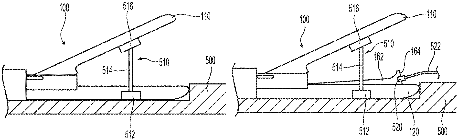
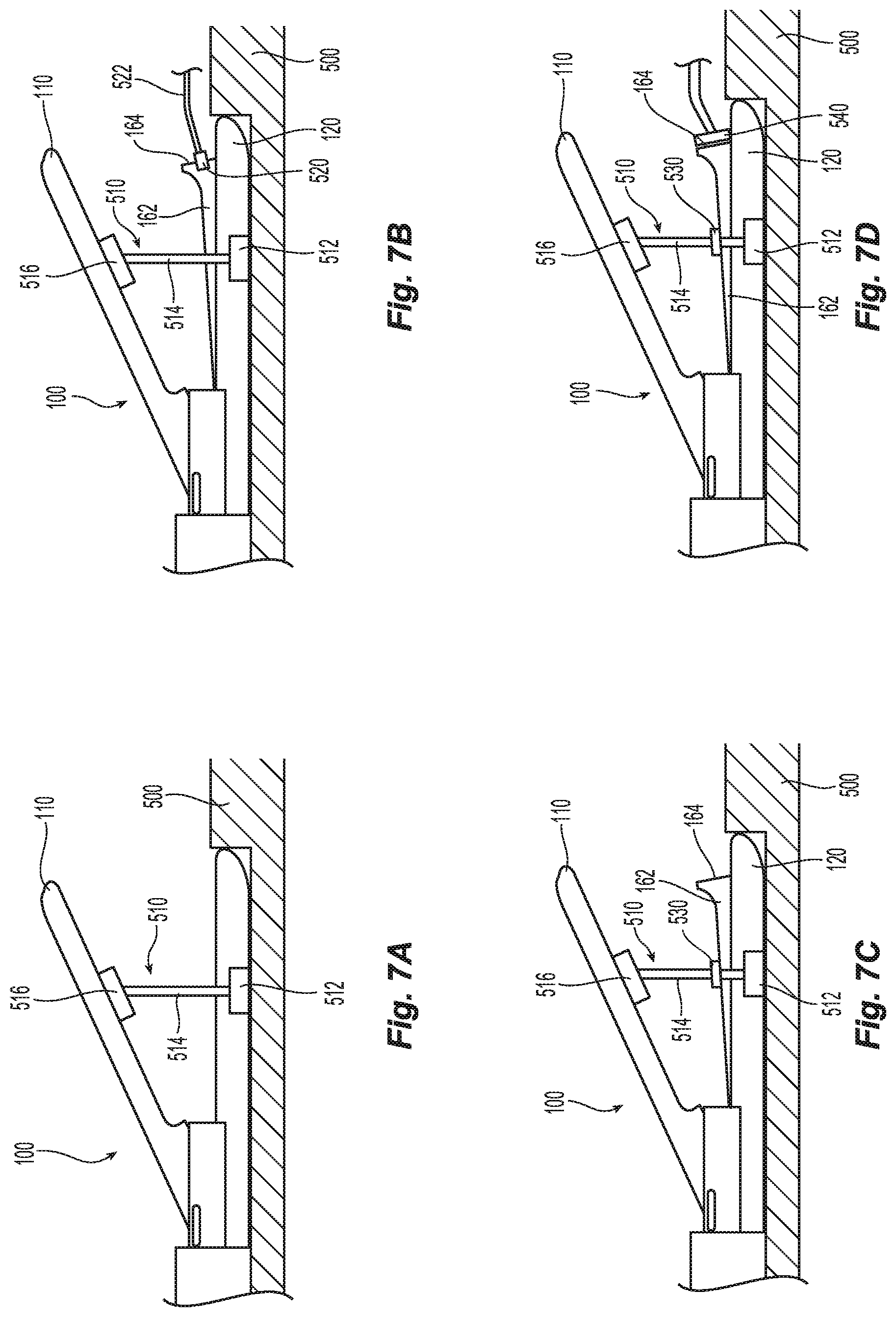
FIGS. 7A-7D are side views of a distal end portion of the front end assembly of FIG. 5 illustrating systems and methods for sharpening the knife thereof without requiring disassembly of the front end assembly.
DETAILED DESCRIPTION
Referring to FIG. 1, a multi-function surgical instrument provided in accordance with the present disclosure is shown generally identified by reference numeral 10. Instrument 10 is configured to operate in both a bipolar mode, e.g., for grasping, treating, and/or mechanically dissecting tissue, and a monopolar mode, e.g., for treating and/or electrically/electromechanically dissecting tissue. Although the present disclosure is shown and described with respect to instrument 10, the systems and methods facilitating reprocessing provided in accordance with the present disclosure are equally applicable for use with any suitable surgical instrument or portion(s) thereof. Obviously, different considerations apply to different instruments; however, the aspects and features of the present disclosure remain generally consistent regardless of the particular instrument provided. For the purposes herein, instrument 10 is generally described.
With reference to FIGS. 1-6, instrument 10 generally includes a housing 20, a handle assembly 30, a trigger assembly 60, a rotation assembly 70, an elongated shaft assembly 80, an end effector assembly 100, a drive assembly 140, a knife assembly 160, bipolar and monopolar activation assemblies 170, 180, respectively, a monopolar assembly 200, and a deployment and retraction mechanism 300. Rotation assembly 70, elongated shaft assembly 80, end effector assembly 100, drive assembly 140, knife assembly 160, and monopolar assembly 200 together form a front end assembly 400 of instrument 10 (see FIGS. 5 and 6).
Instrument 10 also includes an electrosurgical cable (not shown) that connects instrument 10 to a generator (not shown) or other suitable power source. The electrosurgical cable includes wires (not shown) extending therethrough that have sufficient length to extend through housing 20 and/or elongated shaft assembly 80 in order to provide energy to at least one of the electrically-conductive surfaces 112, 122 of jaw members 110, 120, respectively, of end effector assembly 100, e.g., upon activation of bipolar activation switch 172 of bipolar activation assembly 170 in the bipolar mode of operation. Similarly, one or more of the wires of the electrosurgical cable extends through housing 20 and/or elongated shaft assembly 80 in order to provide energy to monopolar assembly 200, e.g., upon activation of either of the monopolar activation switches 182 of monopolar activation assembly 180 in the monopolar mode of operation.
Elongated shaft assembly 80 extends distally from housing 20 and supports end effector assembly 100 at a distal end thereof. End effector assembly 100 includes opposing jaw members 110, 120 pivotably coupled to one another. Each of the jaw members 110, 120 includes an electrically-conductive surface 112, 122 adapted to connect to the source of energy and defines a bipolar configuration in use wherein surface 112 is charged to a first electrical potential and surface 122 is charged to a second, different electrical potential such that an electrical potential gradient is created for conducting energy between surfaces 112, 122 and through tissue grasped therebetween for treating tissue. Bipolar activation switch 172 of bipolar activation assembly 170 (FIG. 1) is operably coupled between the source of energy (not shown) and surfaces 112, 122 via one or more wires (not shown), thus allowing the surgeon to apply bipolar energy to surfaces 112, 122 of jaw members 110, 120, respectively, of end effector assembly 100 during a bipolar mode of operation.
Handle assembly 30 includes a movable handle 40 and a fixed handle 50. Movable handle 40 is movable relative to fixed handle 50 between an initial position, wherein movable handle 40 is spaced-apart from fixed handle 50, and a compressed position, wherein movable handle 40 is compressed towards fixed handle 50. Drive assembly 140 is operably coupled between handle assembly 30 and end effector assembly 100 such that movement of movable handle 40 between the initial position and the compressed position pivots jaw member 110 relative to jaw member 120 between the spaced-apart position and the approximated position, to a threshold force, at which point movable handle 40 is decoupled from jaw member 110 such that jaw member 110 is maintained in position despite further movement of movable handle 40 towards the compressed position. More specifically, when the threshold force is reached, a compression spring 142 (FIG. 6) of drive assembly 140 is compressed, decoupling movable handle 40 from jaw member 110 and allowing further movement of movable handle 40 towards the compressed position without impacting the position of jaw member 110. The threshold force is the force at which the drive force exceeds the spring compression force of compression spring 142. Thus, when the drive force is less than or equal to the spring compression force of compression spring 142, movement of movable handle 40 between the initial position and the compressed position pivots jaw member 110 relative to jaw member 120 between the spaced-apart position and the approximated position. On the other hand, when the drive force exceeds the spring compression force of compression spring 142, jaw member 110 is maintained in position and compression spring 142 is further compressed in response to movement movable handle 40 towards the compressed position.
Continuing with reference to FIGS. 1-4, trigger 62 of trigger assembly 60 is selectively actuatable relative to housing 20 from an un-actuated position to an actuated position. Knife assembly 160 is operably coupled to trigger 62 such that actuation of trigger 62 from the un-actuated position to the actuated position translates a knife 162 (FIGS. 7B-7D) of knife assembly 160 from a retracted position, wherein knife 162 is disposed proximally of jaw members 110, 120, to an extended position, wherein knife 162 extends at least partially between jaw members 110, 120 and through knife channels (not shown) defined within jaw members 110, 120 such that cutting edge 164 of knife 162 cuts tissue grasped between jaw members 110, 120. Movable handle 40 may include a protrusion 42 acting as a knife lockout to inhibit actuation of trigger 62 when movable handle 40 is disposed in the initial position, although other suitable knife lockouts operably coupled between trigger 62 and movable handle 40 are also contemplated.
Rotation of rotation wheel 72 of rotation assembly 70 relative to housing 20 effects corresponding rotation of at least a portion of elongated shaft assembly 80, end effector assembly 100, drive assembly 140, the knife assembly 160, and monopolar assembly 200 relative to housing 20.
Monopolar assembly 200 includes an insulative sheath 210 and an energizable member 220. Insulative sheath 210 is movable relative to end effector assembly 100 between a storage position, wherein insulative sheath 210 is disposed proximally of end effector assembly 100, and a use position, wherein insulative sheath 210 is substantially disposed about end effector assembly 100. Energizable member 220 is coupled to the source of energy (not shown) and monopolar activation assembly 180 (FIG. 1) via one or more wires (not shown) and functions as the active electrode of monopolar assembly 200. Energizable member 220 is movable together with insulative sheath 210 and relative to end effector assembly 100 between a storage position, wherein distal tissue-treating portion 227 of energizable member 220 is positioned more-proximally, and a use position, wherein distal tissue-treating portion 227 of energizable member 220 extends distally from end effector assembly 100 to facilitate treating tissue therewith. Energizable member 220, more specifically, is engaged with insulative sleeve 210 such that energizable member 220 and insulative sleeve 210 move together between their respective storage and use positions (collectively the storage and use positions of monopolar assembly 200). In the use position, insulative sheath 210 serves to electrically insulate end effector assembly 100 from distal tissue-treating portion 227 of energizable member 220, while distal tissue-treating portion 227 extends distally from end effector assembly 100. In the use position, energy may be supplied to distal tissue-treating portion 227 of energizable member 220, e.g., via activation of either of the activation switches 182 of monopolar activation assembly 180 (FIG. 1), for treating tissue in the monopolar mode of operation.
Deployment and retraction mechanism 300 is configured for selectively transitioning monopolar assembly 200 between its storage condition and its use condition. Deployment and retraction mechanism 300 generally includes a gear box 310 mounted within housing 20, a gear assembly 320 operably disposed within gear box 310, a pair of input shafts 330 operably coupled to gear assembly 320 and extending transversely from either side of gear box 310 and outwardly from housing 20 through apertures defined through housing 20, a pair of deployment paddles 340 operably coupled to the input shafts 330, and a slider 360 disposed within housing 20 and operably coupling an output of gear assembly 330 with energizable member 220 of monopolar assembly 200 (which, in turn, is engaged with insulative sleeve 210) such that deployment and retraction mechanism 300 is configured to enable both deployment and retraction of monopolar assembly 200 in a push-push manner, e.g., wherein monopolar assembly 200 is both deployed and retracted by pushing either of paddles 340 in the same direction.
Referring to FIGS. 4-6, with regard to the disassembly, cleaning/disinfection, re-assembly, and sterilization of instrument 10 during reprocessing, the various components and assemblies of instrument 10 and the arrangement thereof make disassembling and re-assembling time consuming and challenging. Therefore, avoiding the need to disassemble portions of instrument 10 is advantageous, assuming the components of these portions to remain in-tact can be readily reconditioned and sterilized for reuse. With respect to knife 162 (FIGS. 7B-7D), for example, it has been found that cutting edge 164 may dull during use, thus requiring sharpening as part of reprocessing instrument 10. Provided below are systems and methods enabling sharpening of cutting edge 164 of knife 162 without requiring disassembly of front end assembly 400 of instrument 10. As such, the disassembly and re-assembly of front end assembly 400 during reprocessing is obviated.
In order to reprocess instrument 10, in embodiments, paddles 340 of deployment and retraction mechanism 300 (FIG. 1) are removed, housing 20 is opened, and the various components therein are removed. More specifically, the various components coupled to front end assembly 400 may be decoupled therefrom to enable front end assembly 400 to be removed as a unit. With front end assembly 400 removed from instrument 10, cutting edge 164 of knife 162 may be sharpened, as detailed below, without disassembly of front end assembly 400. In embodiments, instead of separating front end assembly 400 from instrument 10, cutting edge 164 of knife 162 may be sharpened similarly as detailed below while instrument 10 is fully in-tact or partially disassembled (with front end assembly 400 still assembled therewith).
Turning to FIGS. 7A-7D, and with initial reference to FIG. 7A, in order to sharpen cutting edge 164 of knife 162 without removing knife 162 from front end assembly 400, front end assembly 400, or at least end effector assembly 100 thereof, is placed in a fixture 500 to retain end effector assembly 100 in position. Thereafter, jaw members 110, 120 of end effector assembly 100 are moved to the spaced-apart position and a jack 510 is positioned to maintain jaw members 110, 120 in the spaced-apart position. Jack 510 may include a base 512 engaged with or otherwise disposed on fixture 500, a shaft 514 extending from base 512, and a support 516 disposed at the opposite end of shaft 514 for abutting jaw member 110 to maintain jaw member 110 in the spaced-apart position. Jack 510 may be a stationary fixture or an adjustable fixture. Jaw members 110, 120 may be manually opened and jack 510 thereafter positioned to maintain jaw members 110, 120 in the spaced-apart position, or support 516 of jack 510 may be positioned between jaw members 110, 120 and jack 510 thereafter actuated (in embodiments where jack 510 is adjustable) to elongate shaft 514 to urge jaw member 110 to pivot relative to jaw member 120 to the spaced-apart position, similar to a car jack. In the former embodiments, jack 510 need not be adjustable and may instead simply be a support structure for maintaining jaw members 110, 120 in the spaced-apart position. Other configurations are also contemplated.
Referring to FIG. 7B, with fixture 500 retaining end effector assembly 100 and jack 510 maintaining jaw member 110 in the spaced-apart position, knife 162 is moved to the extended position. Knife 162 may be moved to the extended position using a grasping device 520 coupled to a pull wire 522, as shown, may be moved to the extended position by manipulating knife assembly 160 at the proximal end 165 thereof (see FIG. 6), or may be moved to the extended position in any other suitable manner.
With reference to FIG. 7C, once knife 162 is moved to the extended position, a clamp 530 may be engaged with knife 162 at a position proximally-spaced from cutting edge 164. Clamp 530 may also be engaged with shaft 514 of jack 510, as shown, fixture 500, or any other suitable component to maintain knife 162 in the extended position.
Turning to FIG. 7D, with end effector assembly 100 retained, jaw members 110, 120 disposed in the spaced-apart position, and knife 162 held in the extended position, a knife sharpener 540 may be moved into position to sharpen cutting edge 164 of knife 162. Knife sharpener 540 may be a jig-assisted sharpener, sharpening stone-based sharpener, push-through sharpener, grinder sharpener, belt sharpener, or other suitable knife sharpener and may be manually operated or powered.
Referring again to FIGS. 7A-7D, once cutting edge 164 of knife 162 is sufficiently sharpened, clamp 530 and jack 510 are removed and end effector assembly 100 withdrawn from fixture 500. Thereafter, front end assembly 400 may be flushed with a suitable fluid, e.g., a cleaning solution, to clean front end assembly 400 and remove any debris from the sharpening process. In embodiments, front end assembly 400 may additionally or alternatively be flushed with a suitable fluid, e.g., a cleaning solution, prior to sharpening knife 162 to rid any tissue, blood, and/or other debris accumulated during the previous surgical use, before the sharpening process is performed as detailed above. Front end assembly 400 may further be cleaned, refurbished, and/or otherwise reprocessed, before being re-assembled into instrument 10 and sterilized.
Referring generally to FIGS. 1-7D, in embodiments, sharpening of cutting edge 164 of knife 162 is effected without requiring disassembly of front end assembly 400 from housing 20, handle assembly 30, or trigger assembly 60 and, in embodiments, without requiring any disassembly (or minimal disassembly) of instrument 10. In such embodiments, instrument 10 is placed in fixture 500 to retain end effector assembly 100 in position and movable handle 40 is moved to the initial position to move jaw members 110, 120 of end effector assembly 100 to the spaced-apart position. Thereafter, jack 510 is positioned to maintain jaw members 110, 120 in the spaced-apart position. Next, movable handle 40 is moved to the compressed position or sufficiently to the compressed position such that the knife lockout, e.g., protrusion 42, is cleared and, thus, trigger 62 may be actuated to advance knife 162 to the extended position. More specifically, with jack 510 maintaining jaw members 110, 120 in the spaced-apart position, movable handle 40 is moved towards the compressed position with sufficient force to reach the threshold force such that compression spring 142 (FIG. 6) is compressed, thus allowing movement of movable handle 40 towards the compressed position without impacting the position of jaw members 110, 120 which, as noted above, are maintained in the spaced-apart position via jack 510. Movable handle 40 is maintained, e.g., manually held, latched (with a separate latching device or, in embodiments where so provided, a latch incorporated into instrument 10), or otherwise retained, in the compressed or sufficiently compressed position so as to maintain the knife lockout in a disengaged state.
Next, trigger 62 is actuated (which is permitted, despite jaw members 110, 120 being in the spaced-apart position, since the knife lockout has been cleared, as detailed above), to advance knife 162 to the extended position. Knife 162 may be maintained in the extended position via manually holding trigger 62 in the actuated position, latching (with a separate latching device), otherwise retaining trigger 62, or by holding knife 162, similarly as detailed above. Thereafter, cutting edge 164 of knife 162 may be sharpened similarly as detailed above.
From the foregoing and with reference to the various drawing figures, those skilled in the art will appreciate that certain modifications can also be made to the present disclosure without departing from the scope of the same. While several embodiments of the disclosure have been shown in the drawings, it is not intended that the disclosure be limited thereto, as it is intended that the disclosure be as broad in scope as the art will allow and that the specification be read likewise. Therefore, the above description should not be construed as limiting, but merely as exemplifications of particular embodiments. Those skilled in the art will envision other modifications within the scope and spirit of the claims appended hereto.
* * * * *
D00000
D00001
D00002
D00003
D00004
D00005
D00006
XML
uspto.report is an independent third-party trademark research tool that is not affiliated, endorsed, or sponsored by the United States Patent and Trademark Office (USPTO) or any other governmental organization. The information provided by uspto.report is based on publicly available data at the time of writing and is intended for informational purposes only.
While we strive to provide accurate and up-to-date information, we do not guarantee the accuracy, completeness, reliability, or suitability of the information displayed on this site. The use of this site is at your own risk. Any reliance you place on such information is therefore strictly at your own risk.
All official trademark data, including owner information, should be verified by visiting the official USPTO website at www.uspto.gov. This site is not intended to replace professional legal advice and should not be used as a substitute for consulting with a legal professional who is knowledgeable about trademark law.