Combustor and method for damping vibrational modes under high-frequency combustion dynamics
Portillo Bilbao , et al. Sept
U.S. patent number 10,775,043 [Application Number 15/512,943] was granted by the patent office on 2020-09-15 for combustor and method for damping vibrational modes under high-frequency combustion dynamics. This patent grant is currently assigned to SIEMENS AKTIENGESELLSCHAFT. The grantee listed for this patent is Siemens Aktiengesellschaft. Invention is credited to Christian Beck, Olga Deiss, Juan Enrique Portillo Bilbao, Rajesh Rajaram.


| United States Patent | 10,775,043 |
| Portillo Bilbao , et al. | September 15, 2020 |
Combustor and method for damping vibrational modes under high-frequency combustion dynamics
Abstract
A combustor and a method involving burner mains structurally configured to damp vibrational modes that can develop under high-frequency combustion dynamics are provided. The combustor may include a carrier (12), and a plurality of mains (16) disposed in the carrier. Some of the mains (labeled with the letter X) include a body having a different structural feature relative to the respective bodies of the remaining mains. The mains with the different structural feature may be selectively grouped in the carrier to form at least one set of such mains effective to damp predefined vibrational modes in the combustor.
| Inventors: | Portillo Bilbao; Juan Enrique (Oviedo, FL), Rajaram; Rajesh (Winter Park, FL), Beck; Christian (Essen, DE), Deiss; Olga (Dusseldorf, DE) | ||||||||||
|---|---|---|---|---|---|---|---|---|---|---|---|
| Applicant: |
|
||||||||||
| Assignee: | SIEMENS AKTIENGESELLSCHAFT
(Munich, DE) |
||||||||||
| Family ID: | 1000005054351 | ||||||||||
| Appl. No.: | 15/512,943 | ||||||||||
| Filed: | October 6, 2014 | ||||||||||
| PCT Filed: | October 06, 2014 | ||||||||||
| PCT No.: | PCT/US2014/059272 | ||||||||||
| 371(c)(1),(2),(4) Date: | March 21, 2017 | ||||||||||
| PCT Pub. No.: | WO2016/057009 | ||||||||||
| PCT Pub. Date: | April 14, 2016 |
Prior Publication Data
| Document Identifier | Publication Date | |
|---|---|---|
| US 20170292709 A1 | Oct 12, 2017 | |
| Current U.S. Class: | 1/1 |
| Current CPC Class: | F23R 3/002 (20130101); F23R 3/34 (20130101); F23R 3/346 (20130101); F23R 3/286 (20130101); F23R 2900/00014 (20130101) |
| Current International Class: | F23R 3/34 (20060101); F23R 3/00 (20060101); F23R 3/28 (20060101) |
| Field of Search: | ;60/725 |
References Cited [Referenced By]
U.S. Patent Documents
| 5235814 | August 1993 | Leonard |
| 5685157 | November 1997 | Pandalai et al. |
| 6269646 | August 2001 | Lovett et al. |
| 6430930 | August 2002 | Andersson |
| 6530221 | March 2003 | Sattinger et al. |
| 6595002 | July 2003 | Weisenstein |
| 6931853 | August 2005 | Dawson |
| 7080514 | July 2006 | Bland et al. |
| 8381525 | February 2013 | Elkady |
| 2003/0051478 | March 2003 | Matsuyama |
| 2005/0034918 | February 2005 | Bland et al. |
| 2005/0144956 | July 2005 | Alkabie |
| 2007/0028593 | February 2007 | Guo |
| 2008/0053097 | March 2008 | Han et al. |
| 2008/0141645 | June 2008 | Evulet |
| 2009/0241548 | October 2009 | Danis et al. |
| 2010/0005804 | January 2010 | Chen et al. |
| 2010/0058040 | March 2010 | Helmecke et al. |
| 2010/0319349 | December 2010 | Rajaram et al. |
| 2012/0006028 | January 2012 | Lee et al. |
| 2012/0006029 | January 2012 | Bilbao et al. |
| 2012/0180495 | July 2012 | Uhm |
| 2013/0042619 | February 2013 | Bobba |
| 2013/0104552 | May 2013 | Uhm et al. |
| 2013/0180251 | July 2013 | Hase et al. |
| 2014/0033718 | February 2014 | Manoharan |
| 2014/0090389 | April 2014 | Stuttaford et al. |
| 2014/0109587 | April 2014 | Crothers et al. |
| 2014/0123649 | May 2014 | Portilllo Bilbao et al. |
| 2014/0144152 | May 2014 | Uhm |
| 2014/0157779 | June 2014 | Uhm |
| 2014/0283522 | September 2014 | Boardman |
| 2015/0101332 | April 2015 | Bothien |
| 2017/0328568 | November 2017 | Portillo Bilbao |
| 2019/0056112 | February 2019 | Natarajan |
| 102588503 | Jul 2012 | CN | |||
| 103620307 | Mar 2014 | CN | |||
| 2559944 | Feb 2013 | EP | |||
| H05196232 | Aug 1993 | JP | |||
| 2004509313 | Mar 2004 | JP | |||
| 2010230199 | Oct 2010 | JP | |||
| 2011047401 | Mar 2011 | JP | |||
| 2011516809 | May 2011 | JP | |||
| 2012068015 | Apr 2012 | JP | |||
| 2012149868 | Aug 2012 | JP | |||
| 2014040999 | Mar 2014 | JP | |||
| 2014102064 | Jun 2014 | JP | |||
| 2015532412 | Nov 2015 | JP | |||
| 2015219004 | Dec 2015 | JP | |||
Other References
|
PCT International Search Report and Written Opinion dated Jul. 21, 2015 corresponding to PCT Application No. PCT/US2014/059272 filed Oct. 6, 2014. cited by applicant. |
Primary Examiner: Rodriguez; William H
Claims
What is claimed is:
1. A combustor comprising: a burner carrier; and a plurality of burner mains disposed in the burner carrier, wherein some of the plurality of burner mains each comprises a body having a different structural feature relative to the respective bodies of the remaining burner mains, and further wherein said some of the burner mains having the different structural feature are selectively grouped in the burner carrier to form at least one set of said some of the burner mains having the different structural feature effective to damp predefined vibrational modes in the combustor, wherein the plurality of burner mains is disposed in the burner carrier as an annular arrangement comprising at least two concentric annuli of burner mains, wherein said some of the burner mains having the different structural feature are grouped into respective sets over sectors in said at least two concentric annuli of burner mains, and wherein said respective sets are arranged in three equidistant sectors with an angular separation of 120 degrees.
2. The combustor of claim 1, wherein the different structural feature in said some of the burner mains comprises bodies of different axial length relative to the axial length of the respective bodies of the remaining burner mains.
3. The combustor of claim 1, wherein the different structural feature in said some of the burner mains comprises an axial body extension so that the plurality of burner mains have bodies of different axial length.
4. The combustor of claim 1, wherein the different structural feature in said some of the burner mains comprises a plurality of undulations or castellations constructed at each respective discharge end of said some of the burner mains.
5. The combustor of claim 1, wherein the respective bodies of the plurality of burner mains comprises a tubular body, and wherein the different feature in said some of the burner mains comprises a discharge end defining a cross-sectional area that is slanted relative to a longitudinal axis of the tubular body.
6. The combustor of claim 1, wherein the combustor is a diluted oxygen combustor.
7. A method comprising: providing a burner carrier in a combustor; disposing a plurality of burner mains in the burner carrier; arranging in a body of some of the plurality of burner mains a different structural feature relative to the respective bodies of remaining burner mains; and selectively grouping said some of the burner mains having the different structural feature in the burner carrier, the selectively grouping of said some of the burner mains having the different structural feature forming at least one set of said some of the burner mains effective to damp predefined vibrational modes in the combustor; disposing the plurality of burner mains in the burner carrier in an annular arrangement comprising at least two concentric annuli of burner mains, wherein said some of the burner mains having the different structural feature are grouped into respective sets over sectors in said at least two concentric annuli of burner mains, and wherein said respective sets are arranged in three equidistant sectors with an angular separation of 120 degrees.
8. The method of claim 7, wherein the arranging of the different structural feature in the body of said some of the burner mains is effective to produce a non-coherent response to thermo-acoustic oscillations formed in the combustor.
9. The method of claim 7, wherein the predefined vibrational mode that is damped by said at least one set of said some of the burner mains comprises pressure oscillations selected from the group consisting of circumferential pressure oscillations, radial pressure oscillations, and a combination of circumferential and radial pressure oscillations.
10. The method of claim 7, wherein the arranging of the different structural feature in the body of said some of the burner mains comprises affixing an axial body extension so that the plurality of burner mains have bodies of different axial length.
11. The method of claim 7, wherein the arranging of the different structural feature in the body of said some of the burner mains comprises constructing the plurality of burner mains with bodies of different axial length.
12. The method of claim 7, wherein the arranging of the different structural feature in the body of said some of the burner mains comprises constructing a plurality of undulations or castellations at each respective discharge end of said some of the burner mains.
13. The method of claim 7, wherein the respective bodies of the plurality of burner mains comprises a tubular body, and wherein the different feature in said some of the burner mains comprises a discharge end defining a cross-sectional area that is slanted relative to a longitudinal axis of the tubular body.
Description
BACKGROUND
1. Field
Disclosed embodiments are generally related to a combustor and a method as may be used in a turbine engine, such as a gas turbine engine, and, more particularly, to a combustor and a method involving burner mains configured to damp vibrational modes that can develop under high-frequency combustion dynamics.
2. Description of the Related Art
A turbine engine, such as a gas turbine engine, comprises for example a compressor section, a combustor section and a turbine section. Intake air is compressed in the compressor section and then mixed with a fuel. The mixture is burned in the combustor section to produce a high-temperature and high-pressure working gas directed to the turbine section, where thermal energy is converted to mechanical energy.
During combustion of the mixture, relatively high-frequency thermo-acoustic oscillations can occur in the combustor as a consequence of normal operating conditions depending on fuel/air stoichiometry, total mass flow, and other operating conditions. These thermo-acoustic oscillations can lead to unacceptably high levels of pressure oscillations in the combustor that can result in mechanical and/or thermal fatigue to combustor hardware.
One known technique to mitigate such thermo-acoustic oscillations, involves use of Helmholtz-type resonators. See for example U.S. Pat. No. 7,080,514. Further techniques effective to reliably and cost-effectively mitigate such thermo-acoustic oscillations are desirable.
BRIEF DESCRIPTION OF THE DRAWINGS
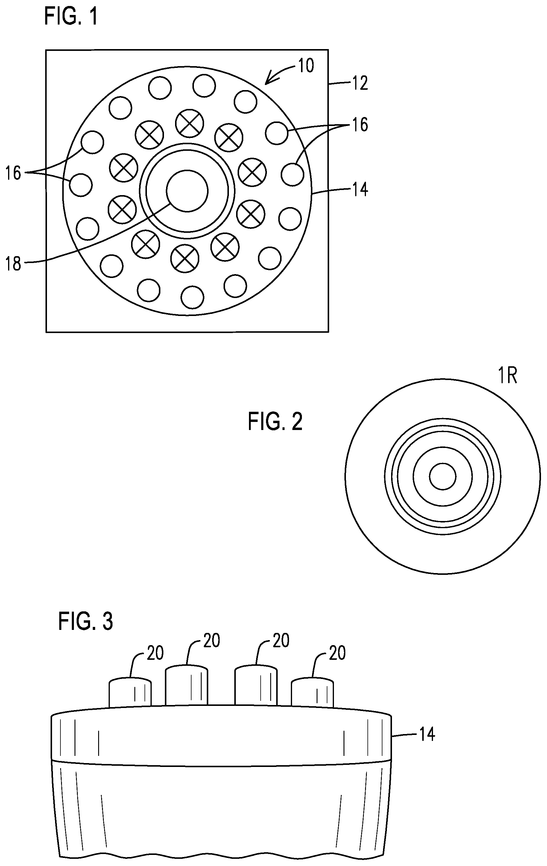
FIG. 1 is a frontal elevational view of one non-limiting embodiment of a disclosed combustor including certain burner mains configured with a body having a different structural feature relative to the bodies of the remaining mains, and selectively grouped to introduce structural asymmetries effective to damp vibrational modes that can develop in the combustor.
FIG. 2 is a non-limiting example plot of pressure oscillations indicative of a 1R vibrational mode that can be effectively damped with the mains arrangement illustrated in FIG. 1.
FIG. 3 is a lateral elevational view of one non-limiting embodiment of a disclosed combustor comprising mains with bodies comprising varying axial length.
FIG. 4 is a frontal elevational view of a disclosed combustor indicating mains configured with a different structural feature that in another non-limiting embodiment may be selectively grouped to damp a 1T vibrational mode, as indicated in the non-limiting example plot of pressure oscillations shown in FIG. 5.
FIG. 6 is a frontal elevational view of a disclosed combustor indicating mains configured with a different structural feature that in yet another non-limiting embodiment may selectively grouped to damp a 2T vibrational mode, as indicated in the non-limiting example plot of pressure oscillations shown in FIG. 7.
FIGS. 8-10 are respective cross-sectional views illustrating further non-limiting embodiments of different structural features that may be configured in certain of the mains to reduce coherent interaction of thermo-acoustic oscillations, and thus effective to damp vibrational modes in the combustor.
DETAILED DESCRIPTION
The inventors of the present invention have recognized certain issues that can arise in the context of some prior art combustors, as may be used in gas turbine engines. High-frequency combustion dynamics, as may comprise any of various acoustic vibrational modes--e.g., a transverse acoustic mode, where acoustic standing waves can propagate along a radial direction, a circumferential direction, or both radial and circumferential directions--can limit the operational envelope of the engine. In prior art combustors involving substantially symmetrical structures, the level of these vibrational modes may be exacerbated by coherent interaction of acoustic pressure oscillations and heat release oscillations (i.e., thermo-acoustic oscillations), and may result in degraded emissions performance of the combustor and may further lead to a shortened lifetime of the combustor hardware. In view of such a recognition, the present inventors propose an improved combustor and method involving burner mains (hereinafter just referred to as mains) configured to reliably and cost-effectively damp vibrational modes that can develop in the combustor. Structural asymmetries arranged in the mains are effective to reduce coherent interaction of such thermo-acoustic oscillations and, thus, effective to damp vibrational modes that can develop under the high-frequency combustion dynamics in the combustor.
In the following detailed description, various specific details are set forth in order to provide a thorough understanding of such embodiments. However, those skilled in the art will understand that embodiments of the present invention may be practiced without these specific details, that the present invention is not limited to the depicted embodiments, and that the present invention may be practiced in a variety of alternative embodiments. In other instances, methods, procedures, and components, which would be well-understood by one skilled in the art have not been described in detail to avoid unnecessary and burdensome explanation.
Furthermore, various operations may be described as multiple discrete steps performed in a manner that is helpful for understanding embodiments of the present invention. However, the order of description should not be construed as to imply that these operations need be performed in the order they are presented, nor that they are even order dependent, unless otherwise indicated. Moreover, repeated usage of the phrase "in one embodiment" does not necessarily refer to the same embodiment, although it may. It is noted that disclosed embodiments need not be construed as mutually exclusive embodiments, since aspects of such disclosed embodiments may be appropriately combined by one skilled in the art depending on the needs of a given application.
The terms "comprising", "including", "having", and the like, as used in the present application, are intended to be synonymous unless otherwise indicated. Lastly, as used herein, the phrases "configured to" or "arranged to" embrace the concept that the feature preceding the phrases "configured to" or "arranged to" is intentionally and specifically designed or made to act or function in a specific way and should not be construed to mean that the feature just has a capability or suitability to act or function in the specified way, unless so indicated.
FIG. 1 is a frontal elevational view of one non-limiting embodiment of a disclosed combustor 10, as may be used in a turbine engine (schematically represented by block 12), such as a gas turbine engine. Combustor 10 includes a carrier 14 and a plurality of mains 16 that may be annularly disposed in the carrier, for example, about a centrally-disposed pilot burner 18. In one non-limiting embodiment, combustor 10 may comprises a diluted oxygen combustion (DOC) type of combustor.
In accordance with aspects of the present invention, some of the plurality of mains (designated with the letter X) have a body having a different structural feature relative to the respective bodies of the remaining mains (not designated with any letter). The mains with the different structural feature can be selectively grouped in the carrier to form one or more sets of such mains effective to damp predefined vibrational modes in the combustor, such as without limitation, a 1R vibrational mode, as represented in the plot of pressure oscillations shown in FIG. 2.
In one non-limiting embodiment, the annular arrangement of mains may comprise at least two concentric annuli of mains and the set of mains with the different structural feature may be a set grouped in the radially inner-most annulus of such at least two concentric annuli of mains, as illustrated in FIG. 1.
As may be appreciated in FIG. 3, in one non-limiting embodiment, the different structural feature configured to introduce structural asymmetries may comprise an axial body extension 20 so that the plurality of mains 16 have bodies of different axial length. For example, the mains may be manufactured with an approximately equal axial length and then body extensions 20 may be subsequently affixed (e.g., welding, threaded connection, etc.) to some of the mains. Alternatively, the mains may be manufactured in lots having a different axial length and thus, in this alternative embodiment, body extensions 20 may not be necessary. It will be appreciated that other forms of structural features may be arranged in the mains to provide such structural asymmetries.
Without limitation, FIGS. 8-10 are respective cross-sectional views illustrating further non-limiting embodiments of different structural features that may constructed in some of the mains to reduce the coherence of such thermo-acoustic oscillations. In one non-limiting embodiment, the respective bodies of the plurality of mains may comprise a tubular body, and, as shown in FIG. 8, some of the mains 16 may comprise a discharge end 22 defining a cross-sectional area that is slanted relative to a longitudinal axis 24 of the tubular body. In another non-limiting embodiment, as shown in FIG. 9, some of the mains 16 may comprise a plurality of undulations 26 that may be constructed at each respective discharge end 22 of such mains. In still another non-limiting embodiment, as shown in FIG. 10, some of the mains 16 may comprise a plurality of castellations 28 that may be constructed at each respective discharge end 22 of such mains. It will be appreciated that the foregoing examples of different structural features that may constructed in some of the mains should be construed in an example sense and not in a limiting sense since aspects of the present invention are not limited to any specific type of structural feature to introduce structural asymmetries.
As may be appreciated in FIGS. 4 and 6, the mains with different structural features (labelled with the letter X) may comprise respective sets 30 of mains selectively grouped (e.g., symmetrically distributed) over sectors 32 in the two concentric annuli of mains. In the non-limiting example shown in FIG. 4, one can appreciate three respective sets 30 arranged in three equidistant sectors 32 with an angular separation of approximately 120 degrees. In this non-limiting example, sets 30 are effective to damp a 1T vibrational mode, as represented in the plot of pressure oscillations shown in FIG. 5.
As a further non-limiting example, FIG. 6 illustrates two respective sets 30 arranged in two equidistant sectors 30 with an angular separation of approximately 180 degrees. In this further non-limiting example, sets 30 are effective to damp a 2T vibrational mode, as represented in the plot of pressure oscillations shown in FIG. 7. It will be appreciated that aspects of the present invention are not limited to damping just the specific vibrational modes illustrated in FIGS. 2, 5 and 7. Broadly, depending on the needs of a given application, the sets of mains may be selectively arranged to damp any vibrational modes as may be defined by their appropriate eigenvectors, or to reduce vibrational mode interactions (e.g., inter-mode coupling) that could arise under the high-frequency combustion dynamics.
While embodiments of the present disclosure have been disclosed in exemplary forms, it will be apparent to those skilled in the art that many modifications, additions, and deletions can be made therein without departing from the spirit and scope of the invention and its equivalents, as set forth in the following claims.
* * * * *
D00000
D00001
D00002
D00003
XML
uspto.report is an independent third-party trademark research tool that is not affiliated, endorsed, or sponsored by the United States Patent and Trademark Office (USPTO) or any other governmental organization. The information provided by uspto.report is based on publicly available data at the time of writing and is intended for informational purposes only.
While we strive to provide accurate and up-to-date information, we do not guarantee the accuracy, completeness, reliability, or suitability of the information displayed on this site. The use of this site is at your own risk. Any reliance you place on such information is therefore strictly at your own risk.
All official trademark data, including owner information, should be verified by visiting the official USPTO website at www.uspto.gov. This site is not intended to replace professional legal advice and should not be used as a substitute for consulting with a legal professional who is knowledgeable about trademark law.