Zoom lens and image pickup apparatus using the same
Kawamura , et al. Sep
U.S. patent number 10,768,396 [Application Number 15/927,152] was granted by the patent office on 2020-09-08 for zoom lens and image pickup apparatus using the same. This patent grant is currently assigned to OLYMPUS CORPORATION. The grantee listed for this patent is OLYMPUS CORPORATION. Invention is credited to Takashi Fujikura, Kazuteru Kawamura, Masaru Morooka, Kenichi Nagasawa.


View All Diagrams
| United States Patent | 10,768,396 |
| Kawamura , et al. | September 8, 2020 |
Zoom lens and image pickup apparatus using the same
Abstract
A zoom lens includes a front unit having a negative refractive power; and a rear unit having a positive refractive power, which includes an aperture stop. The front unit includes a first negative refractive power lens, a second negative refractive power lens, and a third positive refractive power lens. The first lens is nearest to an object, and has a meniscus shape with a convex surface directed toward the object side, and the second lens is on an image side of the first lens, and has a meniscus shape with a convex surface directed toward the object side. The rear unit includes a first lens unit A and a second lens unit B, wherein when zooming from a wide angle end to a telephoto end, a distance between the front unit and the rear unit narrows, and a distance between the first lens unit A and the second lens unit B changes. The first lens unit A includes a first sub-lens unit having a positive refractive power, the aperture stop, and a second sub-lens unit. The second sub-lens unit includes a focusing lens unit, and when focusing, only the focusing lens unit moves along an optical axis, and when zooming, a distance between the first sub-lens unit and the second sub-lens unit changes.
| Inventors: | Kawamura; Kazuteru (Hachioji, JP), Fujikura; Takashi (Fussa, JP), Nagasawa; Kenichi (Hachioji, JP), Morooka; Masaru (Akishima, JP) | ||||||||||
|---|---|---|---|---|---|---|---|---|---|---|---|
| Applicant: |
|
||||||||||
| Assignee: | OLYMPUS CORPORATION (Tokyo,
JP) |
||||||||||
| Family ID: | 1000005042362 | ||||||||||
| Appl. No.: | 15/927,152 | ||||||||||
| Filed: | March 21, 2018 |
Prior Publication Data
| Document Identifier | Publication Date | |
|---|---|---|
| US 20180210179 A1 | Jul 26, 2018 | |
Related U.S. Patent Documents
| Application Number | Filing Date | Patent Number | Issue Date | ||
|---|---|---|---|---|---|
| 15355951 | Nov 18, 2016 | 9958656 | |||
| PCT/JP2015/059053 | Mar 25, 2015 | ||||
Foreign Application Priority Data
| May 19, 2014 [JP] | 2014-103798 | |||
| May 19, 2014 [JP] | 2014-103799 | |||
| May 19, 2014 [JP] | 2014-103800 | |||
| May 30, 2014 [JP] | 2014-111803 | |||
| Jun 6, 2014 [JP] | 2014-117156 | |||
| Current U.S. Class: | 1/1 |
| Current CPC Class: | G02B 15/20 (20130101); G02B 27/0025 (20130101); G02B 5/005 (20130101); G02B 15/177 (20130101) |
| Current International Class: | G02B 15/177 (20060101); G02B 15/20 (20060101); G02B 5/00 (20060101); G02B 27/00 (20060101) |
| Field of Search: | ;359/684,676 |
References Cited [Referenced By]
U.S. Patent Documents
| 5663835 | September 1997 | Shibayama |
| 5668668 | September 1997 | Shibayama et al. |
| 7911707 | March 2011 | Okada |
| 8085475 | December 2011 | Miyazaki et al. |
| 8169718 | May 2012 | Li et al. |
| 8462440 | June 2013 | Eguchi |
| 8830592 | September 2014 | Sato et al. |
| 2006/0050406 | March 2006 | Ishii |
| 2009/0201590 | August 2009 | Sugita |
| 2010/0142060 | June 2010 | Nagatoshi et al. |
| 2012/0019926 | January 2012 | Yamagami |
| 2012/0250168 | October 2012 | Eguchi |
| 2014/0028891 | January 2014 | Otake et al. |
| 2014/0036137 | February 2014 | Inoue |
| 2014/0055659 | February 2014 | Iwamoto |
| 2014/0152887 | June 2014 | Hagiwara |
| 2014/0185143 | July 2014 | Kubota et al. |
| 2014/0211082 | July 2014 | Imaoka |
| 2014/0355129 | December 2014 | Sato et al. |
| 2015/0146085 | May 2015 | Hatada |
| 2017/0068079 | March 2017 | Kawamura |
| 08094935 | Apr 1996 | JP | |||
| 2005107036 | Apr 2005 | JP | |||
| 2007094174 | Apr 2007 | JP | |||
| 2010060612 | Mar 2010 | JP | |||
| 2010176098 | Aug 2010 | JP | |||
| 2010249959 | Nov 2010 | JP | |||
| 2012220527 | Nov 2012 | JP | |||
| 2012220681 | Nov 2012 | JP | |||
| 2012247453 | Dec 2012 | JP | |||
| 2014026169 | Feb 2014 | JP | |||
| 2014032358 | Feb 2014 | JP | |||
| 2014041222 | Mar 2014 | JP | |||
| 2014041245 | Mar 2014 | JP | |||
| 2014109761 | Jun 2014 | JP | |||
| 2014160229 | Sep 2014 | JP | |||
| 2015028530 | Feb 2015 | JP | |||
| 2015087681 | May 2015 | JP | |||
Other References
|
International Preliminary Report on Patentability (and English translation thereof) dated Dec. 1, 2016, issued in corresponding International Application No. PCT/JP2015/059053. cited by applicant . International Search Report (ISR) and Written Opinion dated Jun. 30, 2015 issued in International Application No. PCT/JP2015/059053. cited by applicant. |
Primary Examiner: Greece; James R
Attorney, Agent or Firm: Holtz, Holtz & Volek PC
Parent Case Text
CROSS-REFERENCE TO RELATED APPLICATIONS
The present application is a Divisional application of U.S. Ser. No. 15/355,951, filed Nov. 18, 2016, which is a continuation application of PCT/JP2015/059053 filed on Mar. 25, 2014 which is based upon and claims the benefit of priority from Japanese Patent Application Nos. 2014-103798 filed on May 19, 2014, 2014-103799 filed on May 19, 2014, 2014-103800 filed on May 19, 2014, 2014-111803 filed on May 30, 2014, and 2014-117158 filed on Jun. 6, 2014, the entire contents of all of which are incorporated herein by reference.
Claims
What is claimed is:
1. A zoom lens comprising, in order from an object side to an image side: a front unit having a negative refractive power; and a rear unit having a positive refractive power, which includes an aperture stop, wherein: the front unit includes a first lens having a negative refractive power, a second lens having a negative refractive power, and a third lens having a positive refractive power, the first lens is disposed nearest to an object, and has a meniscus shape of which a convex surface is directed toward the object side, the second lens is disposed on the image side of the first lens, and has a meniscus shape of which a convex surface is directed toward the object side, the rear unit includes, in order from the object side to the image side, a first lens unit A and a second lens unit B, at a time of zooming from a wide angle end to a telephoto end, a distance between the front unit and the rear unit narrows, and a distance between the first lens unit A and the second lens unit B changes, the first lens unit A includes, in order from the object side to the image side, a first sub-lens unit having a positive refractive power, the aperture stop, and a second sub-lens unit, the second sub-lens unit includes a focusing lens unit, at a time of focusing, only the focusing lens unit moves along an optical axis, at the time of zooming, a distance between the first sub-lens unit and the second sub-lens unit changes, and the following conditional expression is satisfied: 65<.nu.d.sub.Fnmax<110, where, .nu.d.sub.Fnmax denotes a maximum of Abbe number from among Abbe numbers for lenses having a negative refractive power in the front unit.
2. The zoom lens according to claim 1, wherein the following conditional expression is satisfied: 1.9<SP.sub.F1<9.0, where, SP.sub.F1=(r.sub.F1o+r.sub.F1i)/(r.sub.F1o-r.sub.F1i), and here r.sub.F1o denotes a paraxial radius of curvature of an object-side surface of the first lens, and r.sub.F1i denotes a paraxial radius of curvature of the image-side surface of the first lens.
3. The zoom lens according to claim 1, wherein the following conditional expression is satisfied: -2.5<FB.sub.w/f.sub.F<-0.3, where, FB.sub.w denotes a back focus at the wide angle end, and f.sub.F denotes a focal length of the front unit.
4. The zoom lens according claim 1, wherein the following conditional expression is satisfied: -2.3<f.sub.w.times.Fno.sub.wmin/f.sub.F<-0.5, where, f.sub.F denotes a focal length of the front unit, f.sub.w denotes a focal length of the overall zoom lens system at the wide angle end, and Fno.sub.wmin denotes a minimum of F-number from among F-numbers at the wide angle end.
5. A zoom lens comprising, in order from an object side to an image side: a front unit having a negative refractive power; and a rear unit having a positive refractive power, which includes an aperture stop, wherein: the front unit includes a first lens having a negative refractive power, a second lens having a negative refractive power, and a third lens having a positive refractive power, the first lens is disposed nearest to an object, and has a meniscus shape of which a convex surface is directed toward the object side, the second lens is disposed on the image side of the first lens, and has a meniscus shape of which a convex surface is directed toward the object side, the rear unit includes, in order from the object side to the image side, a first lens unit A and a second lens unit B, at a time of zooming from a wide angle end to a telephoto end, a distance between the front unit and the rear unit narrows, and a distance between the first lens unit A and the second lens unit B changes, the first lens unit A includes, in order from the object side to the image side, a first sub-lens unit having a positive refractive power, the aperture stop, and a second sub-lens unit, the second sub-lens unit includes a focusing lens unit, at a time of focusing, only the focusing lens unit moves along an optical axis, at the time of zooming, a distance between the first sub-lens unit and the second sub-lens unit changes, and the following conditional expression is satisfied: 1.25<f.sub.Rw/FB.sub.w<5, where, f.sub.Rw denotes a focal length of the rear unit at the wide angle end, and FB.sub.w denotes a back focus at the wide angle end.
6. A zoom lens comprising, in order from an object side to an image side: a front unit having a negative refractive power; and a rear unit having a positive refractive power, which includes an aperture stop, wherein: the front unit includes a first lens having a negative refractive power, a second lens having a negative refractive power, and a third lens having a positive refractive power, the first lens is disposed nearest to an object, and has a meniscus shape of which a convex surface is directed toward the object side, the second lens is disposed on the image side of the first lens, and has a meniscus shape of which a convex surface is directed toward the object side, the rear unit includes, in order from the object side to the image side, a first lens unit A and a second lens unit B, at a time of zooming from a wide angle end to a telephoto end, a distance between the front unit and the rear unit narrows, and a distance between the first lens unit A and the second lens unit B changes, the first lens unit A includes, in order from the object side to the image side, a first sub-lens unit having a positive refractive power, the aperture stop, and a second sub-lens unit, the second sub-lens unit includes a focusing lens unit, at a time of focusing, only the focusing lens unit moves along an optical axis, at the time of zooming, a distance between the first sub-lens unit and the second sub-lens unit changes, and the following conditional expression is satisfied: -25<DTL.sub.w<7, where, DTL.sub.w denotes a distortion at a maximum angle of view at the wide angle end, and is expressed by DTL.sub.w=(IH.sub.w1-IH.sub.w2)/IH.sub.w2.times.100(%), and here IH.sub.w1 denotes an actual image height of an image formed on an image plane by the maximum angle of view at the wide angle end from an infinite object point, and IH.sub.w2 denotes a paraxial image height of an image formed on the image plane by the maximum angle of view at the wide angle end from the infinite object point.
7. The zoom lens according to claim 1, wherein the front unit further includes a fourth lens having a negative refractive power.
8. The zoom lens according to claim 1, wherein the front unit further includes a fourth lens having a negative refractive power, and the fourth lens has a meniscus shape.
9. The zoom lens according to claim 1, wherein the front unit further includes a fourth lens having a negative refractive power, and the fourth lens has a meniscus shape of which a convex surface is directed toward the object side.
10. The zoom lens according to claim 7, wherein the fourth lens is disposed on the image side of the second lens.
11. The zoom lens according to claim 1, wherein the following conditional expression is satisfied: 1.1<|r.sub.F1i/f.sub.F|<3, where, r.sub.F1i denotes a paraxial radius of curvature of an image-side surface of the first lens, and f.sub.F denotes a focal length of the front unit.
12. The zoom lens according to claim 1, wherein the following conditional expression is satisfied: 0.53<.theta.gF.sub.Fn<0.55, where, .theta.gF.sub.Fn denotes a partial dispersion ratio of a lens for which a value of Abbe number is maximum from among lenses having a negative refractive power in the front unit, and is expressed by .theta.gF.sub.Fn=(ng-nF)/(nF-nc), and here ng, nF, and nc denote refractive indices for a g-line, an F-line, and a C-line respectively of the lens for which the value of Abbe number is the maximum.
13. The zoom lens according to claim 1, wherein the following conditional expression is satisfied: 0.01<.theta.gF.sub.Fn+0.0016.times..nu.d-0.6415<0.054, where, .theta.gF.sub.Fn denotes a partial dispersion ratio of a lens for which a value of Abbe number is maximum from among lenses having a negative refractive power in the front unit, and is expressed by .theta.gF.sub.Fn=(ng-nF)/(nF-nc), and here ng, nF, and nc denote refractive indices for a g-line, an F-line, and a C-line respectively of the lens for which the value of Abbe number is the maximum, and .nu.d denotes Abbe number for the lens for which the value of Abbe number is the maximum.
14. The zoom lens according to claim 1, wherein the following conditional expression is satisfied: 0.06<FB.sub.w/LTL.sub.w<0.20, where, FB.sub.w denotes a back focus at the wide angle end, and LTL.sub.w denotes a distance on the optical axis from a surface nearest to object of the zoom lens up to an image plane, at the wide angle end.
15. The zoom lens according to claim 1, wherein the following conditional expression is satisfied: -2.0<f.sub.F/(f.sub.w.times.f.sub.t).sup.1/2<-1.0, where, f.sub.F denotes a focal length of the front unit, f.sub.w denotes a focal length of the overall zoom lens system at the wide angle end, and f.sub.t denotes a focal length of the overall zoom lens system at the telephoto end.
16. The zoom lens according to claim 1, wherein the following conditional expression is satisfied: 1.5<SP.sub.F2<7, where, SP.sub.F2=(r.sub.F2o+r.sub.F2i)/(r.sub.F2o-r.sub.F2i), and here r.sub.F2o denotes a paraxial radius of curvature of an object-side surface of the second lens, and r.sub.F2i denotes a paraxial radius of curvature of an image-side surface of the second lens.
17. The zoom lens according to claim 7, wherein the following conditional expression is satisfied: 0.5<SP.sub.F4<6.0, where, SP.sub.F4=(r.sub.F4o+r.sub.F4i)/(r.sub.F4o-r.sub.F4i), and here r.sub.F4o denotes a paraxial radius of curvature of an object-side surface of the fourth lens, and r.sub.F4i denotes a paraxial radius of curvature of an image-side surface of the fourth lens.
18. The zoom lens according to claim 1, wherein at the time of zooming, the front unit moves.
19. The zoom lens according to claim 1, wherein at the time of zooming, a distance between the first sub-lens unit and the second sub-lens unit is constant.
20. The zoom lens according to claim 1, wherein a part of the second sub-lens unit is the focusing lens unit, and at the time of zooming, the focusing lens unit moves integrally with the second sub-lens unit.
21. The zoom lens according to claim 1, wherein the entire second sub-lens unit is the focusing lens unit.
22. The zoom lens according to claim 1, wherein: the first lens unit A includes a front lens unit having a positive refractive power and a rear lens unit, at the time of zooming, a distance between the front lens unit and the rear lens unit changes, and the front lens unit includes the first sub-lens unit.
23. The zoom lens according to claim 22, wherein the rear lens unit has a negative refractive power.
24. The zoom lens according to claim 22, wherein a part of the rear lens unit is the focusing lens unit, and at the time of focusing, the focusing lens unit moves integrally with the rear lens unit.
25. The zoom lens according to claim 22, wherein the entire rear lens unit is the focusing lens unit.
26. The zoom lens according to claim 1, wherein the first lens unit A includes a motion-blur reducing lens unit, and an image motion due to camera shake is reduced by moving the motion-blur reducing lens unit in a direction perpendicular to the optical axis.
27. The zoom lens according to claim 26, wherein the motion-blur reducing lens unit is disposed on the image side of the focusing lens unit.
28. The zoom lens according to claim 26, wherein the motion-blur reducing lens unit is disposed in the first sub-lens unit.
29. The zoom lens according to claim 28, wherein the entire first sub-lens unit is the motion-blur reducing lens unit.
30. The zoom lens according to claim 1, wherein a lens unit nearest to an image has a positive refractive power.
31. An image pickup apparatus, comprising: the zoom lens according to claim 1; and an image pickup element which has an image pickup surface, and which converts an image formed on the image pickup surface by the zoom lens to an electric signal.
Description
BACKGROUND OF THE INVENTION
Field of the Invention
The present invention relates to a zoom lens and an image pickup apparatus using the same.
Description of the Related Art
As a lens which is capable of capturing a wide range, a wide-angle lens has been known. As a conventional wide angle lens, wide-angle lenses disclosed in Japanese Patent Application Laid-open Publication Nos. 2010-060612, 2010-176098, and 2010-249959 are available.
SUMMARY OF THE INVENTION
A zoom lens according to a first aspect of the present invention comprises in order from an object side to an image side, a front unit having a negative refractive power, and a rear unit having a positive refractive power, which includes an aperture stop, wherein the front unit includes a first lens having a negative refractive power, and the first lens is disposed nearest to an object, and has a meniscus shape of which a convex surface is directed toward the object side, and the rear unit includes in order from the object side to the image side, a first lens unit A and a second lens unit B, and at the time of zooming from a wide angle end to a telephoto end, a distance between the front unit and the rear unit changes.
Moreover, an image pickup apparatus according to the present invention includes the abovementioned zoom lens, and an image pickup element which has an image pickup surface, and which converts an image formed on the image pickup surface by the zoom lens to an electric signal.
BRIEF DESCRIPTION OF THE DRAWINGS
FIG. 1A, FIG. 1B, and FIG. 1C are lens cross-sectional views at the time of focusing to an object at infinity of a zoom lens according to an example 1;
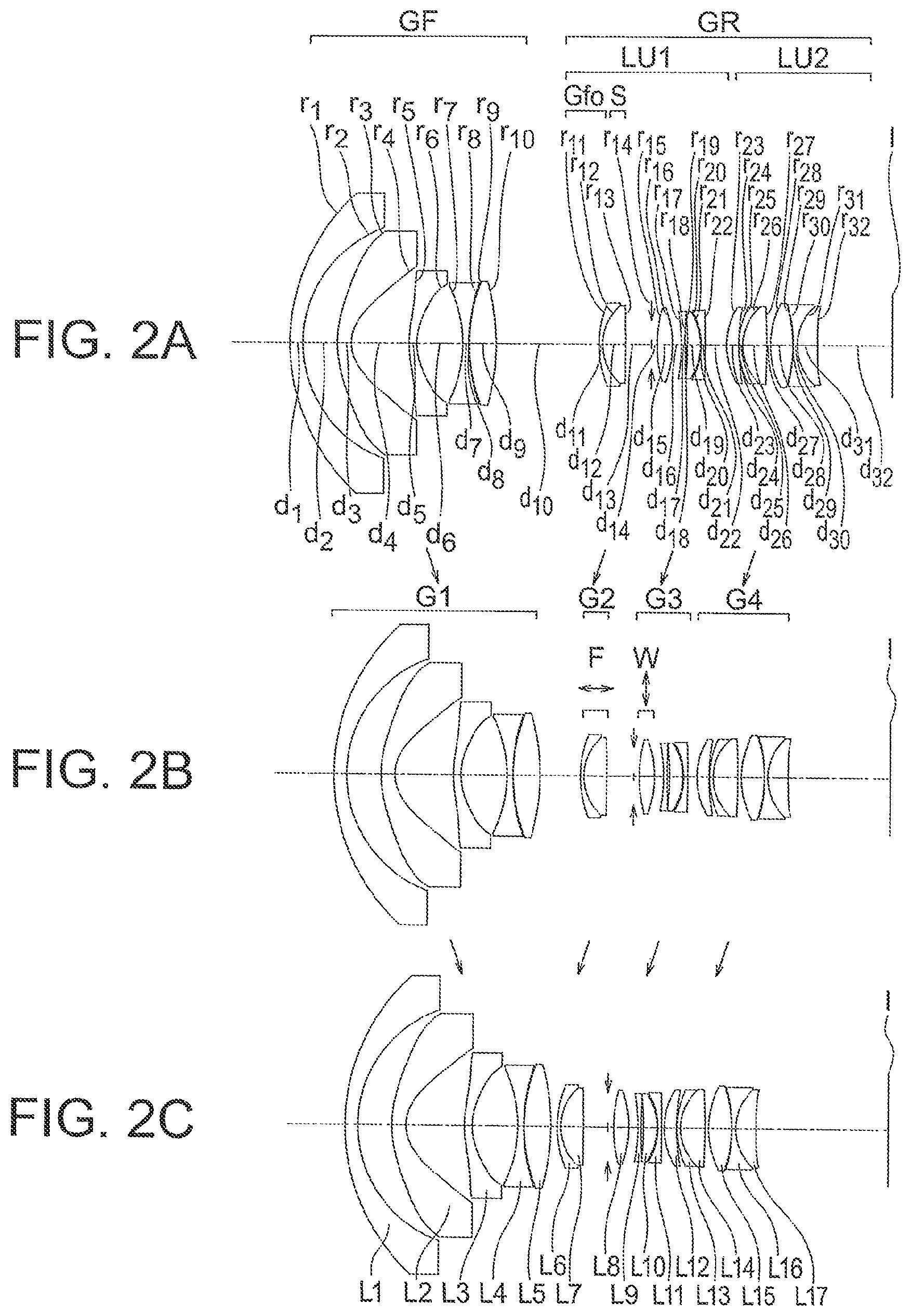
FIG. 2A, FIG. 2B, and FIG. 2C are lens cross-sectional views at the time of focusing to an object at infinity of a zoom lens according to an example 2;
FIG. 3A, FIG. 3B, and FIG. 3C are lens cross-sectional views at the time of focusing to an object at infinity of a zoom lens according to an example 3;
FIG. 4A, FIG. 4B, and FIG. 4C are lens cross-sectional views at the time of focusing to an object at infinity of a zoom lens according to an example 4;
FIG. 5A, FIG. 5B, and FIG. 5C are lens cross-sectional views at the time of focusing to an object at infinity of a zoom lens according to an example 5;
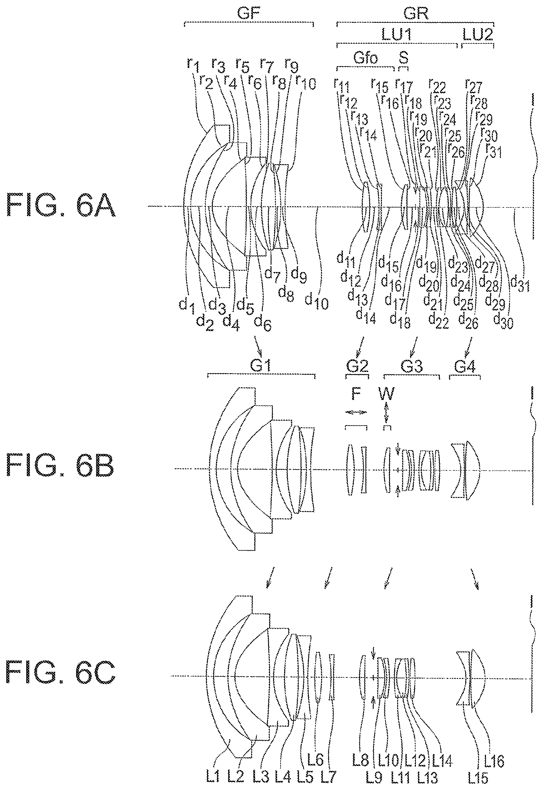
FIG. 6A, FIG. 6B, and FIG. 6C are lens cross-sectional views at the time of focusing to an object at infinity of a zoom lens according to an example 6;
FIG. 7A, FIG. 7B, and FIG. 7C are lens cross-sectional views at the time of focusing to an object at infinity of a zoom lens according to an example 7;
FIG. 8A, FIG. 8B, and FIG. 8C are lens cross-sectional views at the time of focusing to an object at infinity of a zoom lens according to an example 8;
FIG. 9A, FIG. 9B, and FIG. 9C are lens cross-sectional views at the time of focusing to an object at infinity of a zoom lens according to an example 9;
FIG. 10A, FIG. 10B, and FIG. 10C are lens cross-sectional views at the time of focusing to an object at infinity of a zoom lens according to an example 10;
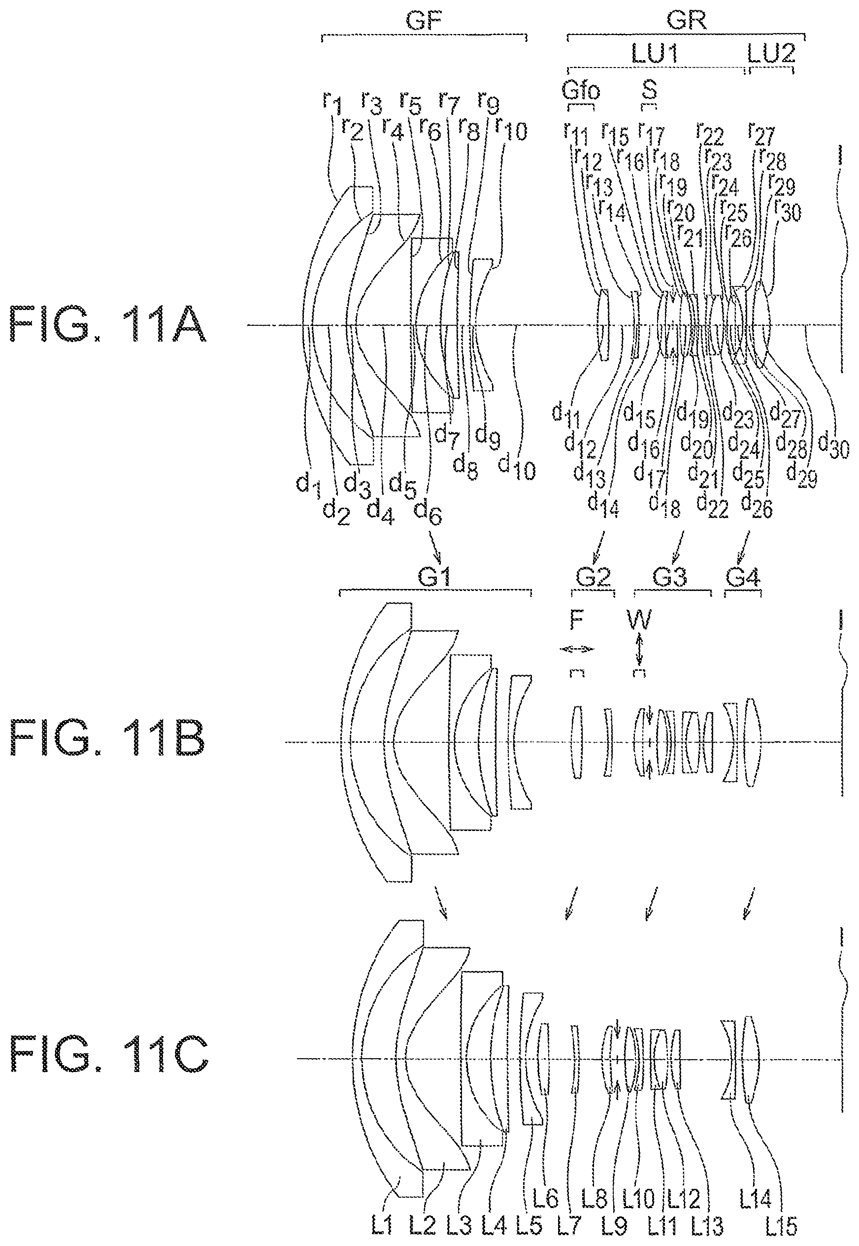
FIG. 11A, FIG. 11B, and FIG. 11C are lens cross-sectional views at the time of focusing to an object at infinity of a zoom lens according to an example 11;
FIG. 12A, FIG. 12B, and FIG. 12C are lens cross-sectional views at the time of focusing to an object at infinity of a zoom lens according to an example 12;
FIG. 13A, FIG. 13B, and FIG. 13C are lens cross-sectional views at the time of focusing to an object at infinity of a zoom lens according to an example 13;
FIG. 14A, FIG. 14B, and FIG. 14C are lens cross-sectional views at the time of focusing to an object at infinity of a zoom lens according to an example 14;
FIG. 15A, FIG. 15B, and FIG. 15C are lens cross-sectional views at the time of focusing to an object at infinity of a zoom lens according to an example 15;
FIG. 16A, FIG. 16B, and FIG. 16C are lens cross-sectional views at the time of focusing to an object at infinity of a zoom lens according to an example 16;
FIG. 17A, FIG. 17B, and FIG. 17C are lens cross-sectional views at the time of focusing to an object at infinity of a zoom lens according to an example 17;
FIG. 18A, FIG. 18B, and FIG. 18C are lens cross-sectional views at the time of focusing to an object at infinity of a zoom lens according to an example 18;
FIG. 19A, FIG. 19B, and FIG. 19C are lens cross-sectional views at the time of focusing to an object at infinity of a zoom lens according to an example 19;
FIG. 20A, FIG. 20B, and FIG. 20C are lens cross-sectional views at the time of focusing to an object at infinity of a zoom lens according to an example 20;
FIG. 21A, FIG. 21B, and FIG. 21C are lens cross-sectional views at the time of focusing to an object at infinity of a zoom lens according to an example 21;
FIG. 22A, FIG. 22B, and FIG. 22C are lens cross-sectional views at the time of focusing to an object at infinity of a zoom lens according to an example 22;
FIG. 23A, FIG. 23B, and FIG. 23C are lens cross-sectional views at the time of focusing to an object at infinity of a zoom lens according to an example 23;
FIG. 24A, FIG. 24B, and FIG. 24C are lens cross-sectional views at the time of focusing to an object at infinity of a zoom lens according to an example 24;
FIG. 25A, FIG. 25B, and FIG. 25c are lens cross-sectional views at the time of focusing to an object at infinity of a zoom lens according to an example 25;
FIG. 26A, FIG. 26B, FIG. 26C, FIG. 26D, FIG. 26E, FIG. 26F, FIG. 26G, FIG. 26H, FIG. 26I, FIG. 26J, FIG. 26K, and FIG. 26L are aberration diagrams at the time of focusing to an object at infinity of the zoom lens according to the example 1;
FIG. 27A, FIG. 27B, FIG. 27C, FIG. 27D, FIG. 27E, FIG. 27F, FIG. 27G, FIG. 27H, FIG. 27I, FIG. 27J, FIG. 27K, and FIG. 27L are aberration diagrams at the time of focusing to an object at a close distance of the zoom lens according to the example 1;
FIG. 28A, FIG. 28B, FIG. 28C, FIG. 28D, FIG. 28E, FIG. 28F, FIG. 28G, FIG. 28H, FIG. 28I, FIG. 28J, FIG. 28K, and FIG. 28L are aberration diagrams at the time of focusing to an object at infinity of the zoom lens according to the example 2;
FIG. 29A, FIG. 29B, FIG. 29C, FIG. 29D, FIG. 29E, FIG. 29F, FIG. 29G, FIG. 29H, FIG. 29I, FIG. 29J, FIG. 29K, and FIG. 29L are aberration diagrams at the time of focusing to an object at a close distance of the zoom lens according to the example 2;
FIG. 30A, FIG. 30B, FIG. 30C, FIG. 30D, FIG. 30E, FIG. 30F, FIG. 30G, FIG. 30H, FIG. 30I, FIG. 30J, FIG. 30K, and FIG. 30L are aberration diagrams at the time of focusing to an object at infinity of the zoom lens according to the example 3;
FIG. 31A, FIG. 31B, FIG. 31C, FIG. 31D, FIG. 31E, FIG. 31F, FIG. 31G, FIG. 31H, FIG. 31I, FIG. 31J, FIG. 31K, and FIG. 31L are aberration diagrams at the time of focusing to an object at a close distance of the zoom lens according to the example 3;
FIG. 32A, FIG. 32B, FIG. 32C, FIG. 32D, FIG. 32E, FIG. 32F, FIG. 32G, FIG. 32H, FIG. 32I, FIG. 32J, FIG. 32K, and FIG. 32L are aberration diagrams at the time of focusing to an object at infinity of the zoom lens according to the example 4;
FIG. 33A, FIG. 33B, FIG. 33C, FIG. 33D, FIG. 33E, FIG. 33F, FIG. 33G, FIG. 33H, FIG. 33I, FIG. 33J, FIG. 33K, and FIG. 33L are aberration diagrams at the time of focusing to an object at a close distance of the zoom lens according to the example 4;
FIG. 34A, FIG. 34B, FIG. 34C, FIG. 34D, FIG. 34E, FIG. 34F, FIG. 34G, FIG. 34H, FIG. 34I, FIG. 34J, FIG. 34K, and FIG. 34L are aberration diagrams at the time of focusing to an object at infinity of the zoom lens according to the example 5;
FIG. 35A, FIG. 35B, FIG. 35C, FIG. 35D, FIG. 35E, FIG. 35F, FIG. 35G, FIG. 35H, FIG. 35I, FIG. 35J, FIG. 35K, and FIG. 35L are aberration diagrams at the time of focusing to an object at a close distance of the zoom lens according to the example 5;
FIG. 36A, FIG. 36B, FIG. 36C, FIG. 36D, FIG. 36E, FIG. 36F, FIG. 36G, FIG. 36H, FIG. 36I, FIG. 36J, FIG. 36K, and FIG. 36L are aberration diagrams at the time of focusing to an object at infinity of the zoom lens according to the example 6;
FIG. 37A, FIG. 37B, FIG. 37C, FIG. 37D, FIG. 37E, FIG. 37F, FIG. 37G, FIG. 37H, FIG. 37I, FIG. 37J, FIG. 37K, and FIG. 37L are aberration diagrams at the time of focusing to an object at a close distance of the zoom lens according to the example 6;
FIG. 38A, FIG. 38B, FIG. 38C, FIG. 38D, FIG. 38E, FIG. 38F, FIG. 38G, FIG. 38H, FIG. 38I, FIG. 38J, FIG. 38K, and FIG. 38L are aberration diagrams at the time of focusing to an object at infinity of the zoom lens according to the example 7;
FIG. 39A, FIG. 39B, FIG. 39C, FIG. 39D, FIG. 39E, FIG. 39F, FIG. 39G, FIG. 39H, FIG. 39I, FIG. 39J, FIG. 39K, and FIG. 39L are aberration diagrams at the time of focusing to an object at a close distance of the zoom lens according to the example 7;
FIG. 40A, FIG. 40B, FIG. 40C, FIG. 40D, FIG. 40E, FIG. 40F, FIG. 40G, FIG. 40H, FIG. 40I, FIG. 40J, FIG. 40K, and FIG. 40L are aberration diagrams at the time of focusing to an object at infinity of the zoom lens according to the example 8;
FIG. 41A, FIG. 41B, FIG. 41C, FIG. 41D, FIG. 41E, FIG. 41F, FIG. 41G, FIG. 41H, FIG. 41I, FIG. 41J, FIG. 41K, and FIG. 41L are aberration diagrams at the time of focusing to an object at a close distance of the zoom lens according to the example 8;
FIG. 42A, FIG. 42B, FIG. 42C, FIG. 42D, FIG. 42E, FIG. 42F, FIG. 42G, FIG. 42H, FIG. 42I, FIG. 42J, FIG. 42K, and FIG. 42L are aberration diagrams at the time of focusing to an object at infinity of the zoom lens according to the example 9;
FIG. 43A, FIG. 43B, FIG. 43C, FIG. 43D, FIG. 43E, FIG. 43F, FIG. 43G, FIG. 43H, FIG. 43I, FIG. 43J, FIG. 43K, and FIG. 43L are aberration diagrams at the time of focusing to an object at a close distance of the zoom lens according to the example 9;
FIG. 44A, FIG. 44B, FIG. 44C, FIG. 44D, FIG. 44E, FIG. 44F, FIG. 44G, FIG. 44H, FIG. 44I, FIG. 44J, FIG. 44K, and FIG. 44L are aberration diagrams at the time of focusing to an object at infinity of the zoom lens according to the example 10;
FIG. 45A, FIG. 45B, FIG. 45C, FIG. 45D, FIG. 45E, FIG. 45F, FIG. 45G, FIG. 45H, FIG. 45I, FIG. 45J, FIG. 45K, and FIG. 45L are aberration diagrams at the time of focusing to an object at a close distance of the zoom lens according to the example 10;
FIG. 46A, FIG. 46B, FIG. 46C, FIG. 46D, FIG. 46E, FIG. 46F, FIG. 46G, FIG. 46H, FIG. 46I, FIG. 46J, FIG. 46K, and FIG. 46L are aberration diagrams at the time of focusing to an object at infinity of the zoom lens according to the example 11;
FIG. 47A, FIG. 47B, FIG. 47C, FIG. 47D, FIG. 47E, FIG. 47F, FIG. 47G, FIG. 47H, FIG. 47I, FIG. 47J, FIG. 47K, and FIG. 47L are aberration diagrams at the time of focusing to an object at a close distance of the zoom lens according to the example 11;
FIG. 48A, FIG. 48B, FIG. 48C, FIG. 48D, FIG. 48E, FIG. 48F, FIG. 48G, FIG. 48H, FIG. 48I, FIG. 48J, FIG. 48K, and FIG. 48L are aberration diagrams at the time of focusing to an object at infinity of the zoom lens according to the example 12;
FIG. 49A, FIG. 49B, FIG. 49C, FIG. 49D, FIG. 49E, FIG. 49F, FIG. 49G, FIG. 49H, FIG. 49I, FIG. 49J, FIG. 49K, and FIG. 49L are aberration diagrams at the time of focusing to an object at a close distance of the zoom lens according to the example 12;
FIG. 50A, FIG. 50B, FIG. 50C, FIG. 50D, FIG. 50E, FIG. 50F, FIG. 50G, FIG. 50H, FIG. 50I, FIG. 50J, FIG. 50K, and FIG. 50L are aberration diagrams at the time of focusing to an object at infinity of the zoom lens according to the example 13;
FIG. 51A, FIG. 51B, FIG. 51C, FIG. 51D, FIG. 51E, FIG. 51F, FIG. 51G, FIG. 51H, FIG. 51I, FIG. 51J, FIG. 51K, and FIG. 51L are aberration diagrams at the time of focusing to an object at a close distance of the zoom lens according to the example 13;
FIG. 52A, FIG. 52B, FIG. 52C, FIG. 52D, FIG. 52E, FIG. 52F, FIG. 52G, FIG. 52H, FIG. 52I, FIG. 52J, FIG. 52K, and FIG. 52L are aberration diagrams at the time of focusing to an object at infinity of the zoom lens according to the example 14;
FIG. 53A, FIG. 53B, FIG. 53C, FIG. 53D, FIG. 53E, FIG. 53F, FIG. 53G, FIG. 53H, FIG. 53I, FIG. 53J, FIG. 53K, and FIG. 53L are aberration diagrams at the time of focusing to an object at a close distance of the zoom lens according to the example 14;
FIG. 54A, FIG. 54B, FIG. 54C, FIG. 54D, FIG. 54E, FIG. 54F, FIG. 54G, FIG. 54H, FIG. 54I, FIG. 54J, FIG. 54K, and FIG. 54L are aberration diagrams at the time of focusing to an object at infinity of the zoom lens according to the example 15;
FIG. 55A, FIG. 55B, FIG. 55C, FIG. 55D, FIG. 55E, FIG. 55F, FIG. 55G, FIG. 55H, FIG. 55I, FIG. 55J, FIG. 55K, and FIG. 55L are aberration diagrams at the time of focusing to an object at a close distance of the zoom lens according to the example 15;
FIG. 56A, FIG. 56B, FIG. 56C, FIG. 56D, FIG. 56E, FIG. 56F, FIG. 56G, FIG. 56H, FIG. 56I, FIG. 56J, FIG. 56K, and FIG. 56L are aberration diagrams at the time of focusing to an object at infinity of the zoom lens according to the example 16;
FIG. 57A, FIG. 57B, FIG. 57C, FIG. 57D, FIG. 57E, FIG. 57F, FIG. 57G, FIG. 57H, FIG. 57I, FIG. 57J, FIG. 57K, and FIG. 57L are aberration diagrams at the time of focusing to an object at a close distance of the zoom lens according to the example 16;
FIG. 58A, FIG. 58B, FIG. 58C, FIG. 58D, FIG. 58E, FIG. 58F, FIG. 58G, FIG. 58H, FIG. 58I, FIG. 58J, FIG. 58K, and FIG. 58L are aberration diagrams at the time of focusing to an object at infinity of the zoom lens according to the example 17;
FIG. 59A, FIG. 59B, FIG. 59C, FIG. 59D, FIG. 59E, FIG. 59F, FIG. 59G, FIG. 59H, FIG. 59I, FIG. 59J, FIG. 59K, and FIG. 59L are aberration diagrams at the time of focusing to an object at a close distance of the zoom lens according to the example 17;
FIG. 60A, FIG. 60B, FIG. 60C, FIG. 60D, FIG. 60E, FIG. 60F, FIG. 60G, FIG. 60H, FIG. 60I, FIG. 60J, FIG. 60K, and FIG. 60L are aberration diagrams at the time of focusing to an object at infinity of the zoom lens according to the example 18;
FIG. 61A, FIG. 61B, FIG. 61C, FIG. 61D, FIG. 61E, FIG. 61F, FIG. 61G, FIG. 61H, FIG. 61I, FIG. 61J, FIG. 61K, and FIG. 61L are aberration diagrams at the time of focusing to an object at a close distance of the zoom lens according to the example 18;
FIG. 62A, FIG. 62B, FIG. 62C, FIG. 62D, FIG. 62E, FIG. 62F, FIG. 62G, FIG. 62H, FIG. 62I, FIG. 62J, FIG. 62K, and FIG. 62L are aberration diagrams at the time of focusing to an object at infinity of the zoom lens according to the example 19;
FIG. 63A, FIG. 63B, FIG. 63C, FIG. 63D, FIG. 63E, FIG. 63F, FIG. 63G, FIG. 63H, FIG. 63I, FIG. 63J, FIG. 63K, and FIG. 63L are aberration diagrams at the time of focusing to an object at a close distance of the zoom lens according to the example 19;
FIG. 64A, FIG. 64B, FIG. 64C, FIG. 64D, FIG. 64E, FIG. 64F, FIG. 64G, FIG. 64H, FIG. 64I, FIG. 64J, FIG. 64K, and FIG. 64L are aberration diagrams at the time of focusing to an object at infinity of the zoom lens according to the example 20;
FIG. 65A, FIG. 65B, FIG. 65C, FIG. 65D, FIG. 65E, FIG. 65F, FIG. 65G, FIG. 65H, FIG. 65I, FIG. 65J, FIG. 65K, and FIG. 65L are aberration diagrams at the time of focusing to an object at a close distance of the zoom lens according to the example 20;
FIG. 66A, FIG. 66B, FIG. 66C, FIG. 66D, FIG. 66E, FIG. 66F, FIG. 66G, FIG. 66H, FIG. 66I, FIG. 66J, FIG. 66K, and FIG. 66L are aberration diagrams at the time of focusing to an object at infinity of the zoom lens according to the example 21;
FIG. 67A, FIG. 67B, FIG. 67C, FIG. 67D, FIG. 67E, FIG. 67F, FIG. 67G, FIG. 67H, FIG. 67I, FIG. 67J, FIG. 67K, and FIG. 67L are aberration diagrams at the time of focusing to an object at a close distance of the zoom lens according to the example 21;
FIG. 68A, FIG. 68B, FIG. 68C, FIG. 68D, FIG. 68E, FIG. 68F, FIG. 68G, FIG. 68H, FIG. 68I, FIG. 68J, FIG. 68K, and FIG. 68L are aberration diagrams at the time of focusing to an object at infinity of the zoom lens according to the example 22;
FIG. 69A, FIG. 69B, FIG. 69C, FIG. 69D, FIG. 69E, FIG. 69F, FIG. 69G, FIG. 69H, FIG. 69I, FIG. 69J, FIG. 69K, and FIG. 69L are aberration diagrams at the time of focusing to an object at a close distance of the zoom lens according to the example 22;
FIG. 70A, FIG. 70B, FIG. 70C, FIG. 70D, FIG. 70E, FIG. 70F, FIG. 70G, FIG. 70H, FIG. 70I, FIG. 70J, FIG. 70K, and FIG. 70L are aberration diagrams at the time of focusing to an object at infinity of the zoom lens according to the example 23;
FIG. 71A, FIG. 71B, FIG. 71C, FIG. 71D, FIG. 71E, FIG. 71F, FIG. 71G, FIG. 71H, FIG. 71I, FIG. 71J, FIG. 71K, and FIG. 71L are aberration diagrams at the time of focusing to an object at a close distance of the zoom lens according to the example 23;
FIG. 72A, FIG. 72B, FIG. 72C, FIG. 72D, FIG. 72E, FIG. 72F, FIG. 72G, FIG. 72H, FIG. 70I, FIG. 70J, FIG. 70K, and FIG. 70L are aberration diagrams at the time of focusing to an object at infinity of the zoom lens according to the example 24;
FIG. 73A, FIG. 73B, FIG. 73C, FIG. 73D, FIG. 73E, FIG. 73F, FIG. 73G, FIG. 73H, FIG. 73I, FIG. 73J, FIG. 73K, and FIG. 73L are aberration diagrams at the time of focusing to an object at a close distance of the zoom lens according to the example 24;
FIG. 74A, FIG. 74B, FIG. 74C, FIG. 74D, FIG. 74E, FIG. 74F, FIG. 74G, FIG. 74H, FIG. 74I, FIG. 74J, FIG. 74K, and FIG. 74L are aberration diagrams at the time of focusing to an object at infinity of the zoom lens according to the example 25;
FIG. 75A, FIG. 75B, FIG. 75C, FIG. 75D, FIG. 75E, FIG. 75F, FIG. 75G, FIG. 75H, FIG. 75I, FIG. 75J, FIG. 75K, and FIG. 75L are aberration diagrams at the time of focusing to an object at a close distance of the zoom lens according to the example 25;
FIG. 76 is a cross-sectional view of an image pickup apparatus;
FIG. 77 is a front perspective view showing the image pickup apparatus schematically;
FIG. 78 is a rear perspective view of the image pickup apparatus; and
FIG. 79 is a structural block diagram showing an internal circuit of main components of the image pickup apparatus.
DETAILED DESCRIPTION OF THE INVENTION
Prior to the explanation of examples, action and effect of embodiments according to certain aspects of the present invention will be described below. In the explanation of the action and effect of the embodiments concretely, the explanation will be made by citing concrete examples. However, similar to a case of the examples to be described later, aspects exemplified thereof are only some of the aspects included in the present invention, and there exists a large number of variations in these aspects. Consequently, the present invention is not restricted to the aspects that will be exemplified.
A zoom lens according to the present embodiment will be described below. To start with, a basic arrangement of the zoom lens will be described below.
A first basic arrangement of the zoom lens according to the present embodiment includes in order from an object side to an image side, a front unit having a negative refractive power, and a rear unit having a positive refractive power, which includes an aperture stop, wherein the front unit includes a first lens having a negative refractive power, a second lens having a negative refractive power, and a third lens having a positive refractive power, and the first lens is disposed nearest to an object, and has a meniscus shape of which a convex surface is directed toward the object side, and the second lens is disposed on the image side of the first lens, and has a meniscus shape of which a convex surface is directed toward the object side, and the rear unit includes in order from the object side to the image side, a first lens unit A and a second lens unit B, and at the time of zooming from a wide angle end to a telephoto end, a distance between the front unit and the rear unit narrows, and a distance between the first lens unit A and the second lens unit B changes, and the first lens unit A includes a focusing lens unit having a positive refractive power, which is disposed on the object side of the aperture stop, and at the time of focusing, only the focusing lens unit moves along an optical axis.
In the first basic arrangement, the zoom lens includes in order from the object side to the image side, the front unit having a negative refractive power and the rear unit having a positive refractive power, which includes an aperture stop. Accordingly, it is possible to let an arrangement of an optical system to be of a retro-focus type. As a result, it is possible to secure a back focus of an appropriate length while having a super-wide angle of view. Here, the super-wide angle of view refers to an angle of view such as 105.degree. or more, and more preferably, 110.degree. or more.
Moreover, in the first basic arrangement, the front unit includes the first lens having a negative refractive power, the second lens having a negative refractive power, and a third lens having a positive refractive power, and the first lens is disposed nearest to the object, and has a meniscus shape of which a convex surface is directed toward the object side, and the second lens is disposed on the image side of the first lens, and has a meniscus shape of which a convex surface is directed toward the object side.
As mentioned above, the front unit has a negative refractive power. Therefore, when the negative refractive power of the front unit is enhanced, it is possible to make a diameter of the optical system small. An amount of curvature of field and astigmatism that occur tends to increase as a height of off-axis principal light ray increases. In an optical system with a super-wide angle of view, the height of an off-axis principal light ray is the maximum while passing through the front unit. Therefore, as the negative refractive power of the front unit is enhanced, the amount of curvature of field and astigmatism that occur is susceptible to increase when the angle of view is let to be super wide.
Therefore, the first lens having a negative refractive power is disposed in the front unit. Moreover, the first lens is disposed nearest to the object in the front unit, and is let to have the meniscus shape of which the convex surface directed toward the object side.
Accordingly, one meniscus lens having a concave surface directed toward the aperture stop is disposed in the front unit where the height of an off-axis principal light ray is the maximum. By making such arrangement, it is possible to refract an off-axis light ray gradually while making the negative refractive power in the front unit large. In other words, it is possible to suppress a sharp refraction of a light ray. As a result, it is possible to make the angle of view super wide while reducing the amount of curvature of field and astigmatism that occur.
Furthermore, the second lens having a negative refractive power is disposed in the front unit. Moreover, the second lens is disposed on the image side of the first lens, and is let to have a meniscus shape of which the convex surface directed toward the object side.
Accordingly, it is possible to make the angle of view further super-wide, while reducing the amount of curvature of field and astigmatism that occur.
Furthermore, the third lens having a positive refractive power is disposed in the front unit. By making such arrangement, it is possible to suppress occurrence of longitudinal chromatic aberration and chromatic aberration of magnification. Moreover, it is possible to reduce an amount of spherical aberration that occurs near the telephoto end.
Moreover, at the time of zooming from the wide angle end to the telephoto end, the distance between the front unit and the rear unit narrows. By making such arrangement, it is possible to achieve a large zooming effect. The distance between the front unit and the rear unit is a paraxial distance.
Moreover, the rear unit includes in order from the object side to the image side, the first lens unit A and the second lens unit B. Furthermore, at the time of zooming from the wide angle end to the telephoto end, the distance between the first lens unit A and the second lens unit B changes. The distance between the first lens unit A and the second lens unit B is a paraxial distance.
As mentioned above, in the basic arrangement, the arrangement of the optical system is of the retro-focus type. In the retro-focus type arrangement, for further thinning of the optical system, it is necessary to make the negative refractive power of the front unit large. Particularly, in a zoom lens with a super-wide angle of view, for shortening the overall length of the optical system upon securing a zooming ratio of 1.9 times or more for instance, the refractive power of not only the front unit but also of the rear unit is required to be made large.
However, when the negative refractive power of the front unit is excessively large, a substantial positive curvature of field occurs in the front unit, and also, at the time of zooming, an off-axis aberration, particularly, the astigmatism is susceptible to fluctuate. Therefore, for reducing the amount of aberration that occurs and suppressing the fluctuation in aberration while maintaining the small-size of the optical system, it is necessary to correct an aberration in the rear unit favorably.
For such reason, the rear unit includes in order from the object side to the image side, the first lens unit A and the second lens unit B. Accordingly, it is possible to correct the aberration in the rear unit favorably. Moreover, at the time of zooming, it is possible to lessen the fluctuation in astigmatism.
Moreover, at the time of zooming from the wide angle end to the telephoto end, the distance between the first lens unit A and the second lens unit B changes. Accordingly, at the time of zooming, it is possible to lessen the fluctuation in aberration.
It is preferable to dispose a positive lens in both the first lens unit A and the second lens unit B, and to make the positive refractive power large. By doing so, it is possible to reduce the amount of curvature of field that occurs.
Moreover, the first lens unit A includes the focusing lens unit having a positive refractive power that is disposed on the object side of the aperture stop, and at the time of focusing, only the focusing lens unit moves along the optical axis.
In the first lens unit A, when the focusing lens unit having a positive refractive power is disposed on the object side of the aperture stop, the focusing lens unit is positioned near the aperture stop, in the vicinity of the wide angle end. Here, a diameter of a light beam becomes small near the aperture stop. Consequently, the focusing lens unit can be disposed at a location where a diameter of a lens in the rear unit becomes further smaller. As a result, it is possible to make the diameter of the focusing lens unit small.
Moreover, at the time of focusing, only the focusing lens unit moves along the optical axis. When such an arrangement is made, on the image side of the aperture stop, there is no lens unit that moves at the time of focusing. Therefore, there is no need to secure a predetermined space on the image side of the aperture stop. As a result, it is possible to make small the diameter of a lens unit positioned on the image side of the aperture stop. The predetermined space is a space that is necessary for the movement of a lens unit at the time of focusing.
Moreover, in an optical system with a super-wide angle of view, it is possible to capture further wider range. In such optical system, the fluctuation in curvature of field that occurs at the time of focusing is a major cause of deterioration of an imaging performance. Especially, the fluctuation in curvature of field at a meridional plane becomes a cause of substantial deterioration of the imaging performance at the time of focusing to an object at a close distance.
The front unit causes the substantial curvature of field at the meridional plane. Therefore, at the time of focusing, when a height of a marginal light ray passing through the front unit fluctuates, the fluctuation in curvature of field at the meridional plane also becomes large. Especially, at the time of focusing to the object at the close distance, the height of a marginal light ray passing through the front unit fluctuates substantially.
Therefore, the focusing lens unit is to be disposed on the object side of the aperture stop. By doing so, the focusing lens unit is positioned on the image side of the front unit. Here, the height of the marginal light ray is lower at the image side of the front unit as compared to the height in the front unit. Consequently, in the focusing lens unit, the height of the marginal light ray becomes low.
In this case, even if the focusing lens unit moves, it is possible to suppress the fluctuation in the height of the marginal light ray passing through the front unit to be small. Accordingly, it is possible to suppress also the fluctuation in curvature of field at the meridional plane. As a result, even at the time of focusing to the object at the close distance, it is possible to maintain high imaging performance of the optical system.
Moreover, a sensitivity of focusing is affected by a magnification of the focusing lens unit and a magnification of the predetermined lens unit. Here, the predetermined lens unit is a lens unit positioned between an image-side surface of the focusing lens unit and an image plane. Therefore, by disposing the focusing lens unit on the object side of the aperture stop and setting appropriately the magnification of the predetermined lens unit, it is possible to improve the sensitivity of focusing. As a result, it is possible to reduce an amount of movement of the focusing lens unit.
Moreover, since it is possible to reduce the amount of movement of the focusing lens unit, at the time of focusing, it is possible to reduce the fluctuation in the height of the marginal light ray in the front unit. Therefore, it is possible to suppress the fluctuation in curvature of field at the meridional plane. As a result, even at the time of focusing to the object at the close distance, it is possible to maintain high imaging performance of the optical system.
As a result, even at the time of focusing to the object at the close distance, it is possible to maintain favorable optical performance. Moreover, it is possible to realize small-sizing and light-weight of the focusing lens unit. Accordingly, it is possible to speed up focusing and to make a drive mechanism of the focusing lens unit light-weight and space-saving.
A separation amount of an axial light ray and a marginal light ray is small near the aperture stop. Therefore, it is preferable to dispose the focusing lens unit near the aperture stop. At this position, a diameter of an axial light beam is large. When the diameter of the axial light beam is large, it is possible to improve the magnification of the focusing lens unit more effectively.
In such manner, when the focusing lens unit is disposed near the aperture stop, it is possible to carry out focusing at a location where the magnification of the focusing lens unit is improved more effectively, or in other words, at a location where the axial light beam is thick. Therefore, by focusing at this position, it is possible to reduce the fluctuation in the height of the marginal light ray in the front unit while improving the sensitivity of focusing.
A second basic arrangement of the zoom lens according to the present embodiment includes in order from an object side to an image side, a front unit having a negative refractive power, and a rear unit having a positive refractive power, which includes an aperture stop, wherein the front unit includes a first lens having a negative refractive power, a second lens having a negative refractive power, and a third lens having a positive refractive power, and the first lens is disposed nearest to an object, and has a meniscus shape of which a convex surface is directed toward the object side, and the second lens is disposed on the image side of the first lens, and has a meniscus shape of which a convex surface is directed toward the object side, and the rear unit includes in order from the object side to the image side, a first lens unit A and a second lens unit B, and at the time of zooming from a wide angle end to a telephoto end, a distance between the front unit and the rear unit narrows, and a distance between the first lens unit A and the second lens unit B changes, and the first lens unit A includes in order from the object side to the image side, a first sub-lens unit having a positive refractive power, the aperture stop, and a second sub-lens unit, and the second sub-lens unit includes a focusing lens unit, and at the time of focusing, only the focusing lens unit moves along an optical axis, and at the time of zooming, a distance between the first sub-lens unit and the second sub-lens unit either changes or is constant.
Description of points in the second basic arrangement that are similar to the points in the first basic arrangement is omitted.
The first lens unit A includes in order from the object side to the image side, the first sub-lens unit having a positive refractive power, the aperture stop, and the second sub-lens unit.
In this case, the first sub-lens unit having a positive refractive power is disposed on the object side of the aperture stop, and the second sub-lens unit is disposed on the image side of the aperture stop. By doing so, correction of spherical aberration and coma can be carried out easily.
Moreover, since the first sub-lens unit has the positive refractive power, the first sub-lens unit has an effect of converging a light beam. Therefore, by disposing the first sub-lens unit nearest to the object in the rear unit, it is possible to make small a diameter of the overall rear unit easily. Moreover, since it is possible to suppress the height of an axial light ray in the rear unit to be low, it is possible to suppress an amount of spherical aberration that occurs.
Moreover, a diameter of a light beam becomes small near the aperture stop. Here, the first sub-lens unit and the second sub-lens unit are disposed to be face-to-face, sandwiching the aperture stop in between. Accordingly, it is possible to make the first sub-lens unit and the second sub-lens unit small-sized. Particularly, it becomes easy to make small a diameter of a lens positioned on the image side of the aperture stop.
Moreover, the second sub-lens unit includes the focusing lens unit, and at the time of focusing, only the focusing lens unit moves along the optical axis.
When the focusing lens unit is disposed in the second sub-lens unit, the focusing lens unit is positioned on the image side of the aperture stop. As mentioned above, the diameter of a light beam becomes small on the image side of the aperture stop. Therefore, the focusing lens unit can be disposed at a location where a diameter of a lens becomes small, in the rear unit. As a result, it is possible to make a diameter of the focusing lens unit small.
Moreover, at the time of focusing, only the focusing lens unit moves along the optical axis. When such an arrangement is made, on the object side of the aperture stop, there is not lens unit that moves at the time of focusing. Therefore, there is no need to secure a predetermined space on the object side of the aperture stop. As a result, it is possible to make small the diameter of a lens unit positioned on the image side of the aperture stop. The predetermined space is a space that is necessary for the movement of a lens unit at the time of focusing.
Moreover, in an optical system with a super-wide angle of view, it is possible to capture further wider range. In such optical system, the fluctuation in curvature of field that occurs at the time of focusing is a major cause of deterioration of an imaging performance. Especially, the fluctuation in the curvature of field at the meridional plane becomes a cause of substantial deterioration of the imaging performance at the time of focusing to an object at a close distance.
The front unit causes a substantial curvature of field at the meridional plane. Therefore, at the time of focusing, when the height of a marginal light ray passing through the front unit fluctuates, the fluctuation in the curvature of field at the meridional plane also becomes large. Especially, at the time of focusing to the object at the close distance, the height of a marginal light ray passing through the front unit fluctuates substantially.
Therefore, the focusing lens unit is to be disposed in the second sub-lens unit. Since the second sub-lens unit is positioned on the image side of the front unit, the focusing lens unit is positioned on the image side of the front unit. Here, the height of the marginal light ray is lower at the image side of the front unit as compared to the height in the front unit. Consequently, in the focusing lens unit, the height of the marginal light ray becomes low.
In this case, even if the focusing lens unit moves, it is possible to suppress the fluctuation in the height of the marginal light ray passing through the front unit to be small. Accordingly, it is possible to suppress also the fluctuation in curvature of field at the meridional plane. As a result, even at the time of focusing to the object at the close distance, it is possible to maintain high imaging performance of the optical system.
Moreover, the sensitivity of focusing is affected by a magnification of the focusing lens unit and a magnification of the predetermined lens unit. Here, the predetermined lens unit is a lens unit positioned between an image-side surface of the focusing lens unit and an image plane. Therefore, by disposing the focusing lens unit on the image side of the aperture stop and setting appropriately the magnification of the predetermined lens unit, it is possible to improve the sensitivity of focusing. As a result, it is possible to reduce an amount of movement of the focusing lens unit.
Moreover, at the time of zooming, the distance between the first sub-lens unit and the second sub-lens unit either changes or is constant.
In a case in which, at the time of zooming, the distance between the first sub-lens unit and the second sub-lens unit is constant, a distance between any lenses in the first lens unit A becomes invariable. Therefore, there is no need to provide a space necessary for the movement of a lens in the first lens unit A. As a result, it is possible to make the first lens unit A small. Moreover, since it is possible to further simplify a structure of a lens barrel, it becomes easier to make a diameter of the lens barrel small. The distance between the first sub-lens unit and the second sub-lens unit is a paraxial distance.
Moreover, at the time of zooming, if a direction of movement or an amount of movement differs for each lens, there arises a need to provide an extra space which is necessary for the movement of a lens in some cases. As a result, sometimes, the overall length of the first lens unit A changes. Whereas, when the first lens unit A moves integrally, all lenses in the first lens unit A move in the same direction by the same amount. In this case, the overall length of the first lens unit A does not change. Therefore, it is possible to make the first lens unit A small-sized.
Moreover, in a case in which the distance between the first sub-lens unit and the second sub-lens unit changes, it is possible to share a zooming ratio by two lens units namely, the first sub-lens unit and the second sub-lens unit. In this case, it is possible to suppress the amount of movement of the first sub-lens unit and the second sub-lens unit at the time of zooming. Therefore, it is possible to shorten the overall length of the optical system.
Moreover, by including the first sub-lens unit and the second sub-lens unit in the first lens unit A, it is possible to impart a zooming effect to both of the first sub-lens unit and the second sub-lens unit. In this case, the magnification necessary for achieving a desired zooming ratio can be shared by the first sub-lens unit and the second sub-lens unit. Consequently, it is possible to suppress the amount of movement at the time of zooming to be small for both the first sub-lens unit and the second sub-lens unit. As a result, it is possible to shorten the overall length of the optical system. The distance between the first sub-lens unit and the second sub-lens unit is a paraxial distance.
Moreover, at the time of zooming, a fluctuation in spherical aberration is susceptible to occur. Therefore, by changing the distance between the two sub-lens units, it is possible to achieve an effect of suppressing mainly the fluctuation in spherical aberration. Making such an arrangement is effective for improving the zooming ratio. Moreover, an amount of fluctuation in curvature of field can also be reduced.
A third basic arrangement of the zoom lens according to the present embodiment includes in order from an object side to an image side, a front unit having a negative refractive power, and a rear unit having a positive refractive power, which includes an aperture stop, wherein the front unit includes a first lens having a negative refractive power, and the first lens is disposed nearest to an object, and has a meniscus shape of which a convex surface is directed toward the object side, and the rear unit includes in order from the object side to the image side, a first lens unit A and a second lens unit B, and at the time of zooming from a wide angle end to a telephoto end, a distance between the from unit and the rear unit narrows, and a distance between the first lens unit A and the second lens unit B changes, and the first lens unit A includes in order from the object side to the image side, a first sub-lens unit having a positive refractive power, an aperture stop, and a second sub-lens unit, and the first lens unit A includes a first focusing lens unit, and a second focusing lens unit is disposed on the image side of the first focusing lens unit, and at the time of focusing, only the first focusing lens unit and the second focusing lens unit move along an optical axis, and at the time of zooming, a distance between the first sub-lens unit and the second sub-lens unit either changes or is constant.
Description of points in the third basic arrangement, that are similar to the points in the first basic arrangement or the second basic arrangement, is omitted.
The first lens unit A includes the first focusing lens unit and the second focusing lens unit on the image side of the first focusing lens unit, and at the time of focusing, only the first focusing lens unit and the second focusing lens unit move along the optical axis.
Since the first lens unit A is disposed in the rear unit, the first lens unit A is positioned on the image side of the front unit. In this case, the focusing lens unit is positioned on the image side of the front unit. As described above, the diameter of a light beam becomes small on the image side of the front unit. Furthermore, the first lens unit A includes the aperture stop. In this case, the focusing lens unit is positioned near the aperture stop. The diameter of a light beam becomes small near the aperture stop. Thus, the focusing lens unit can be disposed at a location where a diameter of a lens becomes small in the rear unit. As a result, it is possible to make a diameter of the focusing lens unit small.
Moreover, at the time of focusing, only the first focusing lens unit and the second focusing lens unit move along the optical axis. When such an arrangement is made, it is possible to make the focusing lens unit light-weight. Moreover, it is possible to make the drive mechanism of the focusing lens unit small-sized and light-weight. As a result, a high-speed focusing drive with less power consumption is possible.
Moreover, in an optical system with a super-wide angle of view, it is possible to capture further wider range. In such optical system, the fluctuation in curvature of field that occurs at the time of focusing is a major cause of deterioration of an imaging performance. Especially, the fluctuation in curvature of field at the meridional plane becomes a cause of substantial deterioration of the imaging performance at the time of focusing to an object at a close distance.
The front unit causes a substantial curvature of field at the meridional plane. Therefore, at the time of focusing, when the height of a marginal light ray passing through the front unit fluctuates, the fluctuation in curvature of field at the meridional plane also becomes large. Especially, at the time of focusing to the object at the close distance, the height of a marginal light ray passing through the front unit fluctuates substantially.
Therefore, the first focusing lens unit is to be disposed in the first lens unit A. Since the first lens unit A is disposed on the image side of the front unit, by doing so, the first focusing lens unit is positioned on the image side of the front unit. Here, the height of the marginal light ray is lower at the image side of the front unit as compared to the height in the front unit. Consequently, in the first focusing lens unit, the height of the marginal light ray becomes low.
In this case, even if the first focusing lens unit moves, it is possible to suppress the fluctuation in the height of the marginal light ray passing through the front unit to be small. Accordingly, it is possible to suppress also the fluctuation in curvature of field at the meridional plane. As a result, even at the time of focusing to the object at the close distance, it is possible to maintain high imaging performance of the optical system.
Moreover, since it is possible to reduce the amount of movement of the first focusing lens unit, at the time of focusing, it is possible to reduce the fluctuation in the height of the marginal light ray in the front unit. Therefore, it is possible to suppress the fluctuation in curvature of field at the meridional plane. As a result, even at the time of focusing to the object at the close distance, it is possible to maintain high imaging performance of the optical system.
As a result, even at the time of focusing to the object at the close distance, it is possible to maintain favorable optical performance. Moreover, it is possible to realize small-sizing and light-weight of the first focusing lens unit. Accordingly, it is possible to speed up focusing and to make a drive mechanism of the first focusing lens unit light-weight and space-saving.
A separation amount of an axial light ray and a marginal light ray is small near the aperture stop. Therefore, it is preferable to dispose the first focusing lens unit near the aperture stop. At this position, a diameter of an axial light beam is large. When the diameter of the axial light beam is large, it is possible to improve the magnification of the first focusing lens unit more effectively.
In such manner, when the first focusing lens unit is disposed near the aperture stop, it is possible to carry out focusing at a location where the magnification of the first focusing lens unit is improved more effectively, or in other words, at a location where the axial light beam is thick. Therefore, by focusing at this position, it is possible to reduce the fluctuation in the height of the marginal light ray in the front unit while improving the sensitivity of focusing.
Moreover, the first lens unit A includes the second focusing lens unit on the image side of the first focusing lens unit. The second focusing lens unit is disposed on the image side of the first focusing lens unit. Consequently, the second focusing lens unit is disposed in the rear unit. Here, as mentioned above, it is possible to make the rear unit small-sized easily. Therefore, it is possible to realize small-sizing and light-weight of the second focusing lens unit.
Moreover, in the focusing by the first focusing lens unit, the fluctuation in curvature of field remains in some cases. Even in such case, it is possible to correct more favorably the fluctuation in curvature of field that has remained. Moreover, even when the refractive power of the front unit and the rear unit is made large, since it is possible to suppress the fluctuation of various aberrations by the two focusing lens units, it is possible to make the optical system further smaller.
Moreover, it is possible to make both the first focusing lens unit and the second focusing lens unit small-sized and light-weight. Therefore, it is possible to make the focusing speed high. Also, it is possible to make a drive mechanism of the focusing lens unit light-weight and space-saving.
Moreover, at the time of zooming, if a direction of movement or an amount of movement differs for each lens, there arises a need to provide an extra space which is necessary for the movement of a lens in some cases. As a result, some times, the overall length of the first lens unit A changes. Whereas, when the first lens unit A moves integrally, all lenses in the first lens unit A move in the same direction by the same amount. In this case, the overall length of the first lens unit A does not change. Therefore, it is possible to make the first lens unit A small-sized.
Moreover, in a case in which the distance between the first sub-lens unit and the second sub-lens unit changes, it is possible to share a zooming ratio by two lens units namely, the first sub-lens unit and the second sub-lens unit. In this case, it is possible to suppress the amount of movement of the first sub-lens unit and the second sub-lens unit at the time of zooming. Therefore, it is possible to shorten the overall length of the optical system.
Moreover, by including the first sub-lens unit and the second sub-lens unit in the first lens unit A, it is possible to impart a zooming effect to both of the first sub-lens unit and the second sub-lens unit. In this case, the magnification necessary for achieving a desired zooming ratio can be shared by the first sub-lens unit and the second sub-lens unit. Consequently, it is possible to suppress the amount of movement at the time of zooming to be small for both the first sub-lens unit and the second sub-lens unit. As a result, it is possible to shorten the overall length of the optical system. The distance between the first sub-lens unit and the second sub-lens unit is a paraxial distance.
Moreover, the spherical aberration is susceptible to occur at the time of zooming. Therefore, by changing the distance between the two sub-lens units, it is possible to achieve an effect of suppressing mainly the fluctuation in the spherical aberration. Making such an arrangement is effective for improving the zooming ratio. Moreover, it is possible to reduce the amount of fluctuation in the curvature of field.
A fourth basic arrangement of the zoom lens according to the present embodiment includes in order from an object side to an image side, a front unit having a negative refractive power, and a rear unit having a positive refractive power, which includes an aperture stop, wherein the front unit includes a first lens having a negative refractive power and a third lens having a positive refractive power, and the first lens is disposed nearest to an object, and has a meniscus shape of which a convex surface is directed toward the object side, and the rear unit includes in order from the object side to the image side, a second lens unit having a positive refractive power which is positioned on the object side of the aperture stop, a third lens unit, a fourth lens unit having a negative refractive power, and a fifth lens unit having a positive refractive power, and either the second lens unit or the third lens unit includes a focusing lens unit, and at the time of zooming from a wide angle end to a telephoto end, distances between the lens units change, and a distance between the front unit and the rear unit narrows.
Description of points in the fourth basic arrangement, that are similar to the points in the first basic arrangement, the second basic arrangement, and the third basic arrangement, is omitted.
According to the abovementioned arrangement of lens units, at the time of zooming from the wide angle end to the telephoto end, a negative distortion that occurs in the front unit can be reduced in the second lens unit and the third lens unit, and an occurrence of curvature field can be reduced favorably in the fourth lens unit.
Moreover, by the second lens unit having a positive refractive power, it is possible to reduce spherical aberration that occur in the front unit, and at the same time, to reduce a fluctuation in spherical aberration at the time of zooming from the wide angle end to the telephoto end. As a result, according to the zoom lens of the present embodiment, it is possible to have high magnification easily.
It is preferable to dispose a positive lens in both the second lens unit and the third lens unit, and to make the refractive power of the positive lens large. By doing so, it is possible to reduce an amount of curvature of field that occurs.
Moreover, either the second lens unit or the third lens unit includes the focusing lens unit.
When the focusing lens unit is disposed in either the second lens unit or the third lens unit, in the vicinity of the wide angle end, the focusing lens is disposed near the aperture stop. Here, the diameter of a light beam becomes small near the aperture stop. Consequently, the focusing lens unit can be disposed at a location where a diameter of a lens in the rear unit becomes further smaller. As a result, it is possible to make the diameter of the focusing lens unit small.
Moreover, it is preferable to dispose the focusing lens unit having a positive refractive power on the object side of the aperture stop, and also it is preferable that only the focusing lens unit moves along the optical axis at the time of focusing. When such an arrangement is made, on the image side of the aperture stop, there is no lens unit that moves at the time of focusing. Therefore, there is no need to secure a predetermined space on the image side of the aperture stop. As a result, it is possible to make small the diameter of a lens unit positioned on the image side of the aperture stop. The predetermined space is a space that is necessary for the movement of a lens unit at the time of focusing.
Moreover, in an optical system with a super-wide angle of view, it is possible to capture further wider range. In such optical system, the fluctuation in curvature of field that occurs at the time of focusing is a major cause of deterioration of an imaging performance. Especially, the fluctuation in the curvature of field at a meridional plane becomes a cause of substantial deterioration of the imaging performance at the time of focusing to an object at a close distance.
The front unit causes a substantial curvature of field at the meridional plane. In this case, at the time of focusing, when the height of a marginal light ray passing through the front unit fluctuates, the fluctuation in curvature of field at the meridional plane also becomes large. Especially, at the time of focusing to the object at the close distance, the height of a marginal light ray passing through the front unit fluctuates substantially.
Therefore, it is preferable to dispose the focusing lens unit on the object side of the aperture stop. By doing so, the focusing lens unit is positioned on the image side of the front unit. Here, the height of the marginal light ray is lower at the image side of the front unit as compared to the height in the front unit. Consequently, in the focusing lens unit, the height of the marginal light ray becomes low.
In this case, even if the focusing lens unit moves, it is possible to suppress the fluctuation in the height of the marginal light ray passing through the front unit to be small. Accordingly, it is possible to suppress also the fluctuation in curvature of field at the meridional plane. As a result, even at the time of focusing to the object at the close distance, it is possible to maintain high imaging performance of the optical system.
Moreover, the sensitivity of focusing is affected by a magnification of the focusing lens unit and a magnification of the predetermined lens unit. Here, the predetermined lens unit is a lens unit positioned between the image-side surface of the focusing lens unit and an image plain. Therefore, by disposing the focusing lens unit on the object side of the aperture stop and setting appropriately the magnification of the predetermined lens unit, it is possible to improve the sensitivity of focusing. As a result, it is possible to reduce the amount of movement of the focusing lens unit.
Moreover, since it is possible to reduce the amount of movement of the focusing lens unit, at the time of focusing, it is possible to reduce the fluctuation in the height of the marginal light ray in the front unit. Therefore, it is possible to suppress the fluctuation in curvature of field at the meridional plane. As a result, even at the time of focusing to the object at the close distance, it is possible to maintain high imaging performance of the optical system.
As a result, even at the time of focusing to the object at the close distance, it is possible to maintain favorable optical performance. Moreover, it is possible to realize small-sizing and light-weight of the focusing lens unit. Accordingly, it is possible to speed up focusing and to make the drive mechanism of the focusing lens unit light-weight and space-saving.
The separation amount of an axial light ray and a marginal light ray is small near the aperture stop. Therefore, it is preferable to dispose the focusing lens unit near the aperture stop. At this position, a diameter of an axial light beam is large. When the diameter of the axial light beam is large, it is possible to improve the magnification of the focusing lens unit more effectively.
In such manner, when the focusing lens unit is disposed near the aperture stop, it is possible to carry out focusing at a location where the magnification of the focusing lens unit is improved more effectively, or in other words, at a location where the axial light beam is thick. Therefore, by focusing at this position, it is possible to reduce the fluctuation in the height of the marginal light ray in the front unit while improving the sensitivity of focusing.
A fifth basic arrangement of the zoom lens according to the present embodiment includes in order from an object side to an image side, a front unit having a negative refractive power, and a rear unit having a positive refractive power, which includes an aperture stop, wherein the front unit includes a first lens having a negative refractive power, a second lens having a negative refractive power, and a third lens having a positive refractive power, and the first lens is disposed nearest to an object, and has a meniscus shape of which a convex surface directed toward the object side, and the second lens is disposed on the image side of the first lens, and has a meniscus shape of which a convex surface is directed toward the object side, and the rear unit includes in order from the object side to the image side, a second lens unit having a positive refractive power which is positioned on the object side of the aperture stop, a third lens unit having a negative refractive power, and a fourth lens unit having a positive refractive power, and either the second lens unit or the third lens unit includes a focusing lens unit, and at the time of zooming from a wide angle end to a telephoto end, distances between the lens units change, and a distance between the front unit and the rear unit narrows.
Description of points in the fourth basic arrangement that are similar to the points in the first basic arrangement to the fourth basic arrangement is omitted.
According to the abovementioned arrangement of lens units, at the time of zooming from the wide angle end to the telephoto end, a negative distortion that occurs in the front unit can be reduced in the second lens unit and the third lens unit. Moreover, it is possible to correct the negative distortion occurring in the front unit by the second lens unit having a positive refractive power and the third lens unit having a negative refractive power.
Next, preferable aspects of the present embodiment will be described below. Repetitive description of same arrangements will be omitted.
It is preferable that a zoom lens according to a first embodiment has the abovementioned first basic arrangement, and the following conditional expressions (1) and (2) are satisfied: 72<.nu.d.sub.Fnmax<110 (1), and -1.45<FB.sub.w/f.sub.F<-0.3 (2),
where,
.nu.d.sub.Fnmax denotes a maximum of Abbe number from among Abbe numbers for lenses having a negative refractive power in the front unit,
FB.sub.w denotes a back focus at the wide angle end, and
f.sub.F denotes a focal length of the front unit.
By exceeding a lower limit value of conditional expression (1), it is possible to reduce an amount of chromatic aberration that occurs in the front unit. Moreover, by falling below an upper limit value of conditional expression (1), it is possible to secure widely a degree of freedom of selecting a glass material.
By exceeding a lower limit value of conditional expression (2), it is possible to shorten the back focus at the wide angle end. As a result, it is possible to make the optical system small-sized. Moreover, since it is possible to suppress the refractive power of the front unit from becoming large, it is possible to reduce an amount of curvature of field and astigmatism that occur.
By falling below an upper limit value of conditional expression (2), it is possible to set the refractive power of the front unit appropriately. As a result, it is possible to make a diameter of the front unit small.
It is preferable that a zoom lens according to a second embodiment has the abovementioned first basic arrangement, and the following conditional expression (3) is satisfied: -1.8<f.sub.w.times.Fno.sub.wmin/f.sub.F<-0.5 (3),
where,
f.sub.w denotes a focal length of the overall zoom lens system at the wide angle end,
Fno.sub.wmin denotes a minimum of F-number from among F-numbers at the wide angle end, and
f.sub.F denotes a focal length of the front unit.
By exceeding a lower limit value of conditional expression (3), it is possible to make the angle of view of the zoom lens super wide while being a zoom lens with small diameter and small F-number. Moreover, by falling below an upper limit value of conditional expression (3), it is possible to make the diameter of the front unit small.
It is preferable that a zoom lens according to a third embodiment has the abovementioned first basic arrangement, and the following conditional expressions (2-1) and (3-1) are satisfied: -1.65<FB.sub.w/f.sub.F<-0.3 (2-1), and -2.3<f.sub.w.times.Fno.sub.wmin/f.sub.F<-0.7 (3-1),
Technical significance of conditional expression (2-1) is same as the technical significance of conditional expression (2). By exceeding a lower limit value of conditional expression (2-1), it is possible to make the refractive power of the rear unit large. Consequently, it is possible to shorten the overall length of the optical system. Moreover, by falling below an upper limit value of conditional expression (2-1), it is possible to make the refractive power of the front unit large. Consequently, it is possible to make the diameter of the optical system small.
Since technical significance of conditional expression (3-1) is same as the technical significance of conditional expression (3), a description thereof is omitted here.
It is preferable that a zoom lens according to a fourth embodiment has the abovementioned first basic arrangement, and the following conditional expression (4) is satisfied: 1.25<f.sub.Rw/FB.sub.w<5 (4),
where,
f.sub.Rw denotes a focal length of the rear unit at the wide angle end, and
FB.sub.w denotes a back focus at the wide angle end.
By exceeding a lower limit value of conditional expression (4), it is possible to reduce an amount of spherical aberration and longitudinal chromatic aberration that occur while securing appropriately the refractive power of the rear unit at the wide angle end. Moreover, since it is possible to shorten the back focus at the wide angle end, it is possible to shorten the overall length of the optical system. Furthermore, since it is possible to make the refractive power of the front unit large, it is possible to make the diameter of the optical system small.
By falling below an upper limit value of conditional expression (4), it is possible to shorten the overall length of the optical system while securing appropriately the refractive power of the rear unit. Furthermore, by making the positive refractive power of the rear unit large, it is possible to reduce an amount of curvature of field that occurs.
It is preferable that a zoom lens according to a fifth embodiment has the abovementioned second basic arrangement, and the following conditional expression (9) is satisfied: 1.9<SP.sub.F1<9.0 (9), where, SP.sub.F1=(r.sub.F1o+r.sub.F1i)/(r.sub.F1o-r.sub.F1i), and here
r.sub.F1o denotes a paraxial radius of curvature of an object-side surface of the first lens, and
r.sub.F1i denotes a paraxial radius of curvature of the image-side surface of the first lens.
By exceeding a lower limit value of conditional expression (9), it is possible to suppress a difference in a curvature of the object-side surface of the first lens and a curvature of the image-side surface of the first lens from becoming excessively large. As a result, it is possible to reduce an amount of astigmatism that occurs.
By falling below an upper limit value of conditional expression (9), it is possible to suppress the difference in the curvature of the object-side surface of the first lens and the curvature of the image-side surface of the first lens from becoming excessively small. In this case, since it is possible to secure the refractive power of appropriate magnitude in the first lens, it is possible to lower a height of a light ray incident on the rear unit. As a result, it is possible to make a lens diameter of the rear unit small. Moreover, since it is possible to make the negative refractive power of the front unit small to some extent, it is possible to suppress an apex of the object-side surface from being positioned on the object side. As a result, it is possible to shorten the overall length of the optical system and to make the optical system small-sized.
It is preferable that a zoom lens according to a sixth embodiment has the abovementioned second basic arrangement, and the following conditional expression (1-1) is satisfied: 65<.nu.d.sub.Fnmax<110 (1-1),
Since technical significance of conditional expression (1-1) is same as the technical significance of conditional expression (1), a description thereof is omitted here.
It is preferable that a zoom lens according to a seventh embodiment has the abovementioned second basic arrangement, and the following conditional expression (2-2) is satisfied: -2.5<FB.sub.w/f.sub.F<-0.3 (2-2),
Since technical significance of conditional expression (2-2) is same as the technical significance of conditional expression (2), a description thereof is omitted here.
It is preferable that a zoom lens according to an eighth embodiment has the abovementioned second basic arrangement, and the following conditional expression (3-2) is satisfied. -2.3<f.sub.w.times.Fno.sub.wmin/f.sub.F<-0.5 (3-2)
Since technical significance of conditional expression (3-2) is same as the technical significance of conditional expression (3), a description thereof is omitted here.
It is preferable that a zoom lens according to a ninth embodiment has the abovementioned second basic arrangement, and conditional expression (4) is satisfied.
It is preferable that a zoom lens according to a tenth embodiment has the abovementioned third basic arrangement, and the front unit includes a third lens having a positive refractive power which is disposed on the aperture-stop side of the first lens.
By making such arrangement, it is possible to suppress an occurrence of longitudinal chromatic aberration and chromatic aberration of magnification. Moreover, it is possible to reduce an amount of spherical aberration that occurs near the telephoto end.
It is preferable that a zoom lens according to an eleventh embodiment has the abovementioned third basic arrangement, and the front unit includes a second lens having a negative refractive power and a third lens having a positive refractive power, and the second lens is disposed on the image side of the first lens, and has a meniscus shape of which a convex surface is directed toward the object side.
Accordingly, two meniscus lenses having a concave surface directed toward the aperture stop are disposed in the front unit for which a height of an off-axis principal light ray is the maximum. By making such arrangement, it is possible to refract an off-axis light ray gradually while making the negative refractive power in the front unit large. In other words, it is possible to suppress a sharp refraction of a light ray. As a result, it is possible to make the angle of view super wide while reducing an amount of curvature of field and astigmatism that occur.
Moreover, by the third lens having a positive refractive power, it is possible to suppress an occurrence of longitudinal chromatic aberration and chromatic aberration of magnification. Also, it is possible to reduce an occurrence of spherical aberration near the telephoto end.
It is preferable that a zoom lens according to a twelfth embodiment has the abovementioned third basic arrangement, and the following conditional expression (1-2) is satisfied: 49<.nu.d.sub.Fnmax<110 (1-2).
Since technical significance of conditional expression (1-2) is same as the technical significance of conditional expression (1), a description thereof is omitted here.
It is preferable that a zoom lens according to a thirteenth embodiment has the abovementioned third basic arrangement, and the following conditional expression (2-2) is satisfied: -2.5<FB.sub.w/f.sub.F<-0.3 (2-2).
Since technical significance of conditional expression (2-2) is same as the technical significance of conditional expression (2), a description thereof is omitted here.
It is preferable that a zoom lens according to a fourteenth embodiment has the abovementioned third basic arrangement, and conditional expression (3-2) is satisfied: -2.3<f.sub.w.times.Fno.sub.wmin/f.sub.F<-0.5 (3-2).
It is preferable that a zoom lens according to a fifteenth embodiment has the abovementioned third basic arrangement, and conditional expression (4) is satisfied.
It is preferable that a zoom lens according to a sixteenth embodiment has the abovementioned fourth basic arrangement, and the following conditional expression (9-1) is satisfied: 1.65<SP.sub.F1<9.0 (9-1).
It is preferable that a zoom lens according to a seventeenth embodiment of the present invention has the abovementioned fourth basic arrangement, and conditional expression (2) is satisfied.
It is preferable that a zoom lens according to an eighteenth embodiment has the abovementioned fourth basic arrangement, and the following conditional expression (1-3) is satisfied: 52<.nu.d.sub.Fnmax<110 (1-3).
It is preferable that a zoom lens according to a nineteenth embodiment has the abovementioned fourth basic arrangement, and conditional expression (4) is satisfied.
It is preferable that a zoom lens according to a twentieth embodiment has the abovementioned fifth basic arrangement, and conditional expressions (1) and (2) are satisfied.
It is preferable that a zoom lens according to a twenty first embodiment has the abovementioned fifth basic arrangement, and conditional expression (4-1) is satisfied: 1.2<f.sub.Rw/FB.sub.w<5 (4-1).
Since technical significance of conditional expression (4-1) is same as the technical significance of conditional expression (4), a description thereof is omitted here.
It is preferable that a zoom lens according to a twenty second embodiment has the abovementioned fifth basic arrangement, and conditional expressions (1), (2-1), and (3-3) are satisfied: -1.8<f.sub.w.times.Fno.sub.wmin/f.sub.F<-0.5 (3-3).
Since technical significance of conditional expression (3-3) is same as the technical significance of conditional expression (3), a description thereof is omitted here.
It is preferable that a zoom lens according to a twenty third embodiment has the abovementioned fifth basic arrangement, and the following conditional expression (16) is satisfied: 2.6<f.sub.3/f.sub.F<15 (16),
where,
f.sub.3 denotes a focal length of the third lens unit, and
f.sub.F denotes a focal length of the front unit.
By exceeding a lower limit value of conditional expression (16), it is possible to make the negative refractive power of the third lens unit large. As a result, it is possible to reduce favorably the negative distortion that may occur in the front unit. Moreover, by falling below an upper limit value of conditional expression (16), it is possible to suppress bending of a marginal light ray, and to make a diameter of the fourth lens unit small. As a result, it is possible to make the overall zoom lens small-sized.
It is preferable that a zoom lens according to a twenty fourth embodiment has the abovementioned fifth basic arrangement, and the following conditional expression (17) is satisfied: -25<f.sub.3/f.sub.w<-4 (17),
where,
f.sub.3 denotes the focal length of the third lens unit, and
f.sub.w denotes the focal length of the overall zoom lens at the wide angle end.
By exceeding a lower limit value of conditional expression (17), it is possible to make the negative refractive power of the third lens unit large. As a result, it is possible to reduce favorably the negative distortion that may occur in the front unit. Moreover, by falling below an upper limit value of conditional expression (17), it is possible to suppress bending of a marginal light, and to make the diameter of the fourth lens unit small. As a result, it is possible to make the overall zoom lens small-sized.
Preferable aspects of the zoom lenses according to the embodiments from the first embodiment to the twenty fourth embodiment will be described below. In the following description, the zoom lenses according to the first embodiment to the twenty fourth embodiment will simply be referred to as `the zoom lens according to the present embodiment`.
In the zoom lens according to the present embodiment, it is preferable that the front unit further includes a fourth lens having a negative refractive power.
By making such arrangement, it is possible to correct favorably the spherical aberration in the front unit, and to suppress a fluctuation in the spherical aberration at the time of zooming. As a result, a favorable optical performance in the entire zoom range is achieved. Moreover, it is possible to make the refractive power of the front unit large while suppressing an occurrence of curvature of field, astigmatism, and chromatic aberration of magnification. As a result, since an entrance pupil is positioned farther on the object side, it is possible to make the diameter of the front unit small. The front unit may further include a lens having a negative refractive power. By making such arrangement, it is possible to further enhance the abovementioned effect.
Moreover, it is preferable that the lens having a negative refractive power is disposed near a lens having a positive refractive power. It is preferable that the fourth lens is disposed near the third lens for example. By making such arrangement, it is possible to further enhance the abovementioned effect.
Moreover, in the zoom lens according to the present embodiment, it is preferable that the front unit further includes a fourth lens having a negative refractive power, and the fourth lens has a meniscus shape.
By making such arrangement, three meniscus lenses are disposed in the front unit. In this case, it is possible to refract gradually a light ray incident on the front unit with a super-wide angle of view by the three meniscus lenses. Moreover, in each meniscus lens, it is possible to refract a light ray gradually while suppressing an angle of incidence of a light ray on a lens to be small. Therefore, at each meniscus lens, it is possible to suppress an occurrence of curvature of field, astigmatism, and chromatic aberration of magnification. The front unit may further include a negative meniscus lens. By making such arrangement, it is possible to further enhance the abovementioned effect.
Moreover, in the zoom lens according to the present embodiment, it is preferable that the front unit further includes a fourth lens having a negative refractive power, and the fourth lens has a meniscus shape of which a convex surface is directed toward the object side.
By making such arrangement, a negative meniscus lens other than the first lens and the second lens, is disposed in the front unit. Here, each of the three meniscus lenses has a convex surface directed toward the object side, or in other words, a concave surface directed toward the image side. In this case, it is possible to suppress a sharp refraction of a light ray while further making the negative refractive power large. Consequently, it is possible to reduce an amount of curvature of field and astigmatism that occur. As a result, further super-widening of the angle of view and small-sizing of the optical system become easy. The front unit may further include a negative meniscus lens having a convex surface directed toward the object side. By making such arrangement, it is possible to further enhance the abovementioned effect.
Moreover, in the zoom lens according to the present embodiment, it is preferable that the fourth lens is disposed on the image side of the second lens.
Accordingly, it is possible to make the refractive power of the front unit large while reducing an amount of curvature of field, astigmatism, and chromatic aberration of magnification that occur. Moreover, since the entrance pupil is positioned farther on the object side, it is possible to make the diameter of the front unit small.
Moreover, in the zoom lens according to the present embodiment, it is preferable that the following conditional expression (5) is satisfied: 1.1<|r.sub.F1i/f.sub.F|<3 (5),
where,
r.sub.F1i denotes a paraxial radius of curvature of an image-side surface of the first lens, and
f.sub.F denotes the focal length of the front unit.
By exceeding a lower limit value of conditional expression (5), it is possible to suppress the refractive power of the first lens from becoming excessively large. As a result, it is possible to suppress an amount of curvature of field, astigmatism, and distortion that occur. Moreover, since it is possible to slim the total thickness of the front unit, it is possible to shorten the overall length of the optical system.
By below an upper limit value of conditional expression (5), the refractive power of the first lens becomes large. In this case, since the lens diameter in the front unit becomes small, it is possible to make the optical system small-sized. Moreover, it is possible to make the refractive power of the front unit large while reducing the occurrence of curvature of field and astigmatism.
Moreover, in the zoom lens according to the present embodiment, it is preferable that the following conditional expression (6) is satisfied: 0.53<.theta.gF.sub.Fn<0.55 (6),
where,
.theta.gF.sub.Fn denotes a partial dispersion ratio of a lens for which a value of Abbe number is the maximum from among lenses having a negative refractive power in the front unit, and is expressed by .theta.gF.sub.Fn=(ng-nF)/(nF-nc), and here
ng, nF, and nc denote refractive indices for a g-line, an F-line, and a C-line respectively of a lens for which the value of Abbe number is the maximum.
By satisfying conditional expression (6), it is possible to suppress an occurrence of chromatic aberration of magnification in the front unit while securing widely a degree of freedom of selecting a glass material to be used in the front unit.
Moreover, in the zoom lens according to the present embodiment, it is preferable that the following conditional expression (7) is satisfied: 0.01<.theta.gF.sub.Fn+0.0016.times..nu.d-0.6415<0.054 (7),
where,
.theta.gF.sub.Fn denotes a partial dispersion ratio of a lens for which a value of Abbe number is the maximum from among lenses having a negative refractive power in the front unit, and is expressed by .theta.gF.sub.Fn=(ng-nF)/(nF-nc), and here
ng, nF, and nc denote refractive indices for a g-line, an F-line, and a C-line respectively of a lens for which the value of Abbe number is the maximum, and
.nu.d denotes Abbe number for the lens for which the value of Abbe number is the maximum.
For suppressing the occurrence of mainly the curvature of field and astigmatism, a plurality of lenses having a negative refractive power is used in the front unit. However, by using lenses having a negative refractive power, mainly the longitudinal chromatic aberration, chromatic aberration of magnification, and spherical aberration occur in some cases. Therefore, by disposing a lens having a positive refractive power in the front unit, it becomes easy to reduce an occurrence of these aberrations. As a result, it becomes easy to secure high optical performance.
Here, for correcting a chromatic aberration favorably while making the negative refractive power of the front unit large, it is preferable that a dispersion of a lens having a positive refractive power is high. However, when the dispersion of the lens having a positive refractive power is high, a secondary spectrum occurs substantially in some cases. Therefore, for the lens having a negative refractive power in the front unit, using a glass material having a peculiarity of being capable of reducing an amount of the secondary spectrum that occurs is effective for correction of the chromatic aberration.
By exceeding a lower limit value of conditional expression (7), it is possible to reduce the amount of secondary spectrum that occurs in the front unit. As a result, it is possible to reduce the amount of longitudinal chromatic aberration and chromatic aberration of magnification that occur.
By falling below an upper limit value of conditional expression (7), it is possible to suppress the excessive correction of the amount of secondary spectrum occurring in the front unit. As a result, it is possible to balance the longitudinal chromatic aberration and chromatic aberration of magnification.
Moreover, in the zoom lens according to the present embodiment, it is preferable that the following conditional expression (8) is satisfied: 0.06<FB.sub.w/LTL.sub.w<0.20 (8),
where,
FB.sub.w denotes the back focus at the wide angle end, and
LTL.sub.w denotes a distance on an optical axis from a surface nearest to object of the zoom lens up to an image plane, at the wide angle end.
By exceeding a lower limit value of conditional expression (8), it is possible to shorten the overall length of the optical system with respect to the back focus, at the wide angle end. As a result, it is possible to shorten the overall length of the optical system. The axial distance is a paraxial distance.
By falling below an upper limit value of conditional expression (8), it is possible to shorten the back focus with respect to the overall length of the optical system. As a result, it is possible to shorten the overall length of the optical system. Moreover, in a case of disposing an optical element in the optical system, it is possible to secure adequately a space for disposing the optical element. Consequently, it becomes easy to secure high optical performance in the entire zoom range.
Moreover, in the zoom lens according to the present embodiment, it is preferable that the following conditional expression (9) is satisfied: 1.9<SP.sub.F1<9.0 (9), where, SP.sub.F1=(r.sub.F1o+r.sub.F1i)/(r.sub.F1o-r.sub.F1i), and here
r.sub.F1o denotes a paraxial radius of curvature of an object-side surface of the first lens, and
r.sub.F1i denotes the paraxial radius of curvature of the image-side surface of the first lens.
Since the technical significance of conditional expression (9) has already been described above, a description thereof is omitted here.
Moreover, in the zoom lens according to the present embodiment, it is preferable that at least one of the lenses in the front unit, having a meniscus shape of which the convex surface is directed toward the object side, is an aspheric lens which satisfies the following conditional expression (10): 30.degree.<ASP.sub.R.theta.<70.degree. (10),
where,
ASP.sub.R.theta. denotes an inclination of a plane at a predetermined position of a surface on the image side of the at least one of the lenses, and here
the predetermined position is a position at which an effective aperture of the at least one of the lenses is the maximum, and
the inclination of the plane is an angle at which a tangent of the plane at the predetermined position intersects the optical axis.
By exceeding a lower limit value of conditional expression (10), it is possible to reduce an amount of astigmatism and distortion that occur. By falling below an upper limit value of conditional expression (10), it is possible to reduce an amount of chromatic aberration of magnification that occurs.
Moreover, in the zoom lens according to the present embodiment, it is preferable that at the time of zooming, the front unit moves.
Accordingly, it is possible to reduce an amount of curvature of field that occurs in the entire zoom range.
Moreover, in the zoom lens according to the present embodiment, it is preferable that the first lens unit A includes in order from the object side to the image side, a first sub-lens unit and a second sub-lens unit, and at the time of zooming, a distance between the first sub-lens unit and the second sub-lens unit is constant.
In this case, at the time of zooming, a distance between any lenses in the first lens unit A becomes invariable. Therefore, there is no need of providing a space necessary for the movement of a lens in the first lens unit A. As a result, it is possible to make the first lens unit A small-sized. Moreover, since it is possible to further simplify a structure of a lens barrel, it becomes easier to make a diameter of the lens barrel small. The distance between the first sub-lens unit and the second sub-lens unit is a paraxial distance.
Moreover, at the time of zooming, if a direction of movement or an amount of movement differs for each lens, there arises a need to provide an extra space which is necessary for the movement of a lens in some cases. As a result, some times, the overall length of the first lens unit A changes. Whereas, when the first lens unit A moves integrally, all lenses in the first lens unit A move in the same direction by the same amount. In this case, the overall length of the first lens unit A does not change. Therefore, it is possible to make the first lens unit small-sized.
Moreover, in the zoom lens according to the present embodiment, it is preferable that the first lens unit A includes in order from the object side to the image side, a first sub-lens unit and a second sub-lens unit, and at the time of zooming, a distance between the first sub-lens unit and the second sub-lens unit changes.
By making such arrangement, it is possible to share a zooming ratio by two lens units namely, the first sub-lens unit and the second sub-lens unit. In this case, it is possible to suppress an amount of movement of the first sub-lens unit and the second sub-lens unit at the time of zooming. Therefore, it is possible to shorten the overall length of the optical system.
Moreover, by including the first sub-lens unit and the second sub-lens unit in the first lens unit A, it is possible to impart a zooming effect to both of the first sub-lens unit and the second sub-lens unit. In this case, the magnification necessary for achieving a desired zooming ratio can be shared by the first sub-lens unit and the second sub-lens unit. Consequently, it is possible to suppress the amount of movement at the time of zooming to be small for both the first sub-lens unit and the second sub-lens unit. As a result, it is possible to shorten the overall length of the optical system. The distance between the first sub-lens unit and the second sub-lens unit is a paraxial distance.
Moreover, at the time of zooming, the fluctuation in the spherical aberration is susceptible to occur. Therefore, by changing the distance between the two sub-lens units, it is possible to achieve an effect of suppressing mainly the fluctuation in the spherical aberration. Making such arrangement is effective for improving the zooming ratio. Moreover, an amount of fluctuation in the curvature of field can also be reduced.
Moreover, in the zoom lens according to the present embodiment, it is preferable that a part of the first sub-lens unit is the focusing lens unit, and at the time of zooming, the focusing lens unit moves integrally with the first sub-lens unit.
By making such arrangement, in zooming, it is possible to make the movement of the focusing lens unit simplified. Moreover, since only the focusing lens unit moves at the time of focusing, it is possible to make the focusing lens unit light-weight. Moreover, it is also possible to make a drive mechanism of the focusing lens unit small-sized and light-weight. As a result, a high-speed focusing drive with less power consumption is possible.
Moreover, in the zoom lens according to the present embodiment, it is preferable that the entire first sub-lens unit is the focusing lens unit.
Since the rear unit includes the aperture stop, it is possible to position the first sub-lens unit near the aperture stop. Consequently, by letting the entire first sub-lens unit to be the focusing lens unit, the focusing lens unit is positioned near the aperture stop.
The height of an off-axis light ray is low near the aperture stop. Therefore, for an off-axis light ray that passes through the focusing lens unit, a change in the height or a change in the angle of a light ray due to zooming is small. As a result, it is possible to reduce an amount of fluctuation in the off-axis aberration, particularly a coma, in the entire zoom range.
Moreover, by making such arrangement, it is possible to have a common drive mechanism for zooming and focusing. Consequently, it is possible to make a lens-frame structure simplified and small-sized.
Moreover, in the zoom lens according to the present embodiment, it is preferable that the first sub-lens unit has a positive refractive power.
Since the rear unit includes the aperture stop, the first sub-lens unit having a positive refractive power can be disposed on the object side of the aperture stop. In this case, the second sub-lens unit is disposed on the image side of the aperture stop. By making such arrangement, it is possible to correct the spherical aberration and the coma easily.
Moreover, since the first sub-lens unit has a positive refractive power, the first sub-lens unit has an effect of converging a light beam. Therefore, by disposing the first sub-lens unit nearest to object in the rear unit, it is possible to make small a diameter of the overall rear unit easily. Moreover, since it is possible to suppress the height of an axial light ray in the rear unit to be low, it is possible to suppress an amount of spherical aberration that occurs.
Moreover, in the zoom lens according to the present embodiment, it is preferable that the first lens unit A includes in order from the object side to the image side, the focusing lens unit, and a second sub-lens unit, and at the time of zooming, a distance between the focusing lens unit and the second sub-lens unit changes.
Accordingly, it is possible to reduce an amount of fluctuation in the curvature of field at the time of zooming. The distance between the focusing lens unit and the second sub-lens unit is a paraxial distance.
Moreover, in the zoom lens according to the present embodiment, it is preferable that the first lens unit A includes a motion-blur reducing lens unit, and image motion due to camera shake is reduced by moving the motion-blur reducing lens unit in a direction perpendicular to the optical axis.
A camera shake causes an image blur. Therefore, the image blur is to be corrected by moving the motion-blur reducing lens unit in the direction perpendicular to the optical axis. As mentioned above, the front unit has a negative refractive power. Therefore, the motion-blur reducing lens unit is to be disposed on the image side of the front unit, and a positive refractive power is to be imparted to the motion-blur reducing lens unit. By making such arrangement, it is possible to improve magnification of the motion-blur reducing lens unit. In other words, it is possible to make an amount of movement of image even larger with respect to an amount of movement of the motion-blur reducing lens unit. As a result, it is possible to improve the sensitivity of motion-blur reduction.
Moreover, in the zoom lens according to the present embodiment, it is preferable that the motion-blur reducing lens unit is disposed on the image side of the focusing lens unit.
It is preferable that the motion-blur reducing lens unit is capable of moving at a higher speed. Moreover, it is preferable that a range of movement is narrow. For this, it is desirable that a diameter of the motion-blur reducing lens unit is as small as possible. In other words, it is desirable to let a lens (lens unit) at a position at which a light beam becomes thinner to be the motion-blur reducing lens unit.
A light beam emerged from the focusing lens unit passes through the aperture stop. Consequently, a diameter of the light beam is small on the image side of the focusing lens unit. Therefore, by disposing the motion-blur reducing lens unit here, it is possible to make the diameter of the motion-blur reducing lens unit small. As a result, the image blur can be reduced favorably.
Moreover, in the zoom lens according to the present embodiment, it is preferable that the motion-blur reducing lens unit is disposed in the first sub-lens unit, and an image blur due to camera shake is reduced by moving the motion-blur reducing lens unit in a direction perpendicular to the optical axis.
It is preferable that the motion-blur reducing lens unit is capable of moving at a higher speed. Moreover, it is preferable that the range of movement is narrow. For this, it is desirable that the diameter of the motion-blur reducing lens unit is as small as possible. In other words, it is desirable to let a lens (lens unit) at a position at which a light beam becomes thinner to be the motion-blur reducing lens unit.
Since the rear unit includes the aperture stop, the first sub-lens unit can be disposed near the aperture stop. Consequently, by disposing the motion-blur reducing lens unit in the first sub-lens unit, it is possible to dispose the motion-blur reducing lens unit near the aperture stop. By making such arrangement, it is possible to reduce the motion blur at a location where the magnification of the motion-blur reducing lens unit is improved even more effectively, or in other words, at a location where an axial light beam is thick. As a result, it is possible to improve the sensitivity of the motion-blur reducing lens unit.
Similar is a case when the first sub-lens unit is disposed near the aperture stop.
Moreover, in the zoom lens according to the present embodiment, it is preferable that the motion-blur reducing lens unit is disposed in the first sub-lens unit.
It is preferable that the motion-blur reducing lens unit is capable of moving at a higher speed. Moreover, it is preferable that the range of movement is narrow. For this, it is desirable that the diameter of the motion-blur reducing lens unit is as small as possible. In other words, it is desirable to let a lens (lens unit) at a position at which a light beam becomes thinner to be the motion-blur reducing lens unit.
The first sub-lens unit is disposed near the aperture stop. Consequently, by disposing the motion-blur reducing lens unit in the first sub-lens unit, it is possible to dispose the motion-blur reducing lens unit near the aperture stop. By making such arrangement, it is possible to reduce the motion blur at a location where the magnification of the motion-blur reducing lens unit is improved even more effectively, or in other words, at a location where an axial light beam is thick. As a result, it is possible to improve the sensitivity of the motion-blur reducing lens unit.
Moreover, in the zoom lens according to the present embodiment, it is preferable that the motion-blur reducing lens unit is disposed in the second sub-lens unit.
It is preferable that the motion-blur reducing lens unit is capable of moving at a higher speed. Moreover, it is preferable that the range of movement is narrow. For this, it is desirable that the diameter of the motion-blur reducing lens unit is as small as possible. In other words, it is desirable to let a lens (lens unit) at a position at which a light beam becomes thinner to be the motion-blur reducing lens unit.
The second sub-lens unit is disposed near the aperture stop. Consequently, by disposing the motion-blur reducing lens unit in the second sub-lens unit, it is possible to dispose the motion-blur reducing lens unit near the aperture stop. By making such arrangement, it is possible to reduce the motion blur at a location where the magnification of the motion-blur reducing lens unit is improved even more effectively, or in other words, at a location where an axial light beam is thick. As a result, it is possible to improve the sensitivity of the motion-blur reducing lens unit.
Moreover, in the zoom lens according to the present embodiment, it is preferable that either the second lens unit or the third lens unit includes the motion-blur reducing lens unit, and it is preferable to reduce the image blur caused due to camera shake by moving the motion-blur reducing lens unit in a direction perpendicular to the optical axis.
A camera shake causes an image blur. Therefore, the image blur is to be corrected by moving the motion-blur reducing lens unit in the direction perpendicular to the optical axis. By making such arrangement, it is possible to improve magnification of the motion-blur reducing lens unit. In other words, it is possible to make an amount of movement of image even larger with respect to an amount of movement of the motion-blur reducing lens unit. As a result, it is possible to improve the sensitivity of the motion-blur reduction.
Moreover, it is preferable that the second lens unit includes the motion-blur reducing lens unit, and it is preferable to reduce the image blur due to camera shake by moving the motion-blur reducing lens unit in a direction perpendicular to the optical axis.
As mentioned above, the front unit has a negative refractive power. Therefore, the motion-blur reducing lens unit is disposed on the image side of the front unit, and a positive refractive power is imparted to the second lens unit which includes the motion-blur reducing lens unit. As a result, it is possible to further improve the sensitivity of the motion-blur reduction.
Moreover, it is preferable that the second lens unit is the motion-blur reducing lens unit, and it is preferable to reduce the image motion due to camera shake by moving the motion-blur reducing lens unit in a direction perpendicular to the optical axis.
Accordingly, it is possible to suppress an occurrence of tilt error in the motion-blur reducing lens unit, and to secure more stable performance.
Moreover, it is preferable that the third lens unit includes the motion-blur reducing lens unit, and it is preferable to reduce the image blur due to camera shake by moving the motion-blur reducing lens unit in a direction perpendicular to the optical axis.
Moreover, it is preferable that the third lens unit is the motion-blur reducing lens unit, and it is preferable to reduce the image motion due to camera shake by moving the motion-blur reducing lens unit in a direction perpendicular to the optical axis.
Accordingly, it is possible to suppress an occurrence of tilt error in the motion-blur reducing lens unit, and to secure a more stable performance.
Moreover, in the zoom lens according to the present embodiment, it is preferable that the motion-blur reducing lens unit is disposed on the image side of the focusing lens unit.
It is preferable that the motion-blur reducing lens unit is capable of moving at a higher speed. Moreover, it is preferable that a range of movement is narrow. For this, it is desirable that the diameter of the motion-blur reducing lens unit is as small as possible. In other words, it is desirable to let a lens (lens unit) at a position at which a light beam becomes thinner to be the motion-blur reducing lens unit.
A light beam emerged from the focusing lens unit passes through the aperture stop. Consequently, a diameter of the light beam is small on the image side of the focusing lens unit. Therefore, by disposing the motion-blur reducing lens unit here, it is possible to make the diameter of the motion-blur reducing lens unit small. As a result, the image blur can be reduced favorably.
Moreover, in the zoom lens according to the present embodiment, it is preferable that the motion-blur reducing lens unit has a negative refractive power.
Accordingly, the motion-blur reducing lens unit is to be positioned at a portion where the light beam has become thinner. As a result, it is possible to lessen a diameter and a range of the motion-blur reducing lens unit.
Moreover, in the zoom lens according to the present embodiment, it is preferable that the entire first sub-lens unit is the motion-blur reducing lens unit.
By making such arrangement, it is possible to eliminate the tilt error that occurs in the first sub-lens unit compared to the case in which a part of the first sub-lens unit is the motion-blur reducing lens unit. As a result, it is possible to secure a more stable reduction performance.
Moreover, in the zoom lens according to the present embodiment, it is preferable that the following conditional expression (11) is satisfied: -25<DTL.sub.w<7 (11),
where,
DTL.sub.w denotes a distortion at the maximum angle of view at the wide angle end, and is expressed by DTL.sub.w=(IH.sub.w1-IH.sub.w2)/IH.sub.w2.times.100(%), and here
IH.sub.w1 denotes an actual image height of an image formed on an image plane by the maximum angle of view at the wide angle end from an infinite object point, and
IH.sub.w2 denotes a paraxial image height of an image formed on the image plane by the maximum angle of view at the wide angle end from the infinite object point.
By setting appropriately an amount of distortion that occurs, it is possible to make the diameter of the optical system small while facilitating shortening of the overall length of the optical system and super-widening the angle of view by making the refractive power of the front unit large.
By exceeding a lower limit value of conditional expression (11), it is possible to reduce an amount of barrel distortion that occurs. As a result, it is possible to enhance a perspective effect. Moreover, when the distortion is corrected electrically, deterioration of an image can occur due to a peripheral portion of the image being elongated. However, it is possible to suppress the deterioration.
By falling below an upper limit value of conditional expression (11), it is possible to make the diameter of the front unit small. As a result, it is possible to make the optical system small-sized.
Moreover, it is preferable that the zoom lens according to the present embodiment includes a predetermined lens unit, and the predetermined lens unit is a lens unit positioned between an image-side surface of the focusing lens unit and the image plane, and the following conditional expression (12) is satisfied: 0.10<|MG.sub.fob.sup.2.times.(MG.sub.fo.sup.2-1)|<3.0 (12),
where,
MG.sub.fo denotes a lateral magnification of the focusing lens unit at an arbitrary position, and
MG.sub.fob denotes a lateral magnification of the predetermined lens unit at a position same as the arbitrary position.
By exceeding a lower limit value of conditional expression (12), it is possible to lessen an amount of movement of the focusing lens unit. As a result, it is possible to shorten the overall length of the optical system. By falling below an upper limit value of conditional expression (12), it is possible to carry out a position-control of the focusing lens unit easily. As a result, it is possible to carry out an accurate focusing.
Moreover, in the zoom lens according to the present embodiment, it is preferable that the following conditional expression (13) is satisfied: -2.0<f.sub.F/(f.sub.w.times.f.sub.t).sup.1/2<-1.0 (13),
where,
f.sub.F denotes the focal length of the front unit,
f.sub.w denotes the focal length of the overall zoom lens system at the wide angle end, and
f.sub.t denotes a focal length of the overall zoom lens system at the telephoto end.
Conditional expression (13) is related to a ratio of the focal length of the front unit and a product of the focal length at the wide angle end and the focal length at the telephoto end.
By exceeding a lower limit value of conditional expression (13), it is possible to suppress the refractive power of the front unit from becoming excessively large. As a result, it is possible to reduce an amount of astigmatism and an amount of chromatic aberration of magnification at the wide angle end.
By falling below an upper limit value of conditional expression (13), since it is possible to make the refractive power of the front unit adequately large, it is possible to position the entrance pupil on the object side. As a result, it is possible to make the diameter of the front unit small.
Moreover, in the zoom lens according to the present embodiment, it is preferable that the following conditional expression (14) is satisfied: 1.6<SP.sub.F2<6 (14), where, SP.sub.F2=r.sub.F2o+r.sub.F2i)/(r.sub.F2o-r.sub.F2i), and here
r.sub.F2o denotes a paraxial radius of curvature of an object-side surface of the second lens, and
r.sub.F2i denotes a paraxial radius of curvature of an image-side surface of the second lens.
By exceeding a lower limit value of conditional expression (14), at the wide angle end, it is possible to shorten the overall length of the optical system with respect to the back focus. As a result, it is possible to shorten the overall length of the optical system.
By falling below an upper limit value of conditional expression (14), at the wide angle end, it is possible to shorten the back focus with respect to the overall length of the optical system. As a result, it is possible to shorten the overall length of the optical system. Moreover, in a case of disposing an optical element in the optical system, it is possible to secure adequately a space for disposing the optical element. Consequently, it is possible to make favorable an optical performance in the entire zoom range.
Moreover, in the zoom lens according to the present embodiment, it is preferable that the following conditional expression (14-1) is satisfied: 1.5<SP.sub.F2<7 (14-1), where, SP.sub.F2=(r.sub.F2o+r.sub.F2i)/(r.sub.F2o-r.sub.F2i), and here
r.sub.F2o denotes the paraxial radius of curvature of the object-side surface of the second lens, and
r.sub.F2i denotes the paraxial radius of curvature of the image-side surface of the second lens.
By exceeding a lower limit value of conditional expression (14-1), it is possible to suppress an inflection of the second lens from becoming excessively large, and to suppress an occurrence of astigmatism.
By falling below an upper limit value of conditional expression (14-1), since it is possible to set appropriately a curvature of the second lens, it is possible to suppress an apex of the object-side surface from being positioned farther on the object side. As a result, it is possible to shorten the overall length of the optical system, and to make the optical system small-sized. Moreover, it is possible to make the diameter of a lens barrel small.
Moreover, in the zoom lens according to the present embodiment, it is preferable that the following conditional expression (15) is satisfied: 0.5<SP.sub.F4<6.0 (15), where, SP.sub.F4=(r.sub.F4o+r.sub.F4i)/(r.sub.F4o-r.sub.F4i), and here
r.sub.F4o denotes a paraxial radius of curvature of an object-side surface of the fourth lens, and
r.sub.F4i denotes a paraxial radius of curvature of an image-side surface of the fourth lens.
By exceeding a lower limit value of conditional expression (15), at the wide angle end, it is possible to shorten the overall length of the optical system with respect to the back focus. As a result, it is possible to further shorten the overall length of the optical system.
By falling below an upper limit value of conditional expression (15), at the wide angle end, it is possible to shorten the back focus with respect to the overall length of the optical system. As a result, it is possible to further shorten the overall length of the optical system. Moreover, in a case of disposing an optical element in the optical system, it is possible to secure adequately a space for disposing the optical element. Consequently, it is possible to make favorable an optical performance in the entire zoom range.
By falling below the upper limit value of conditional expression (15), since it is possible to set appropriately a curvature of the second lens, it is possible to suppress an apex of the object-side surface from being positioned farther on the object side. As a result, it is possible to shorten the overall length of the optical system, and to make the optical system small-sized. Moreover, it is possible to make the diameter of a lens barrel small.
Moreover, in the zoom lens according to the present embodiment, it is preferable that the focusing lens unit is disposed nearest to object in the first lens unit A.
Since the rear unit includes the aperture stop, the height of a marginal light ray is lower at a position of the aperture stop as compared to the height in the front unit. Moreover, in the rear unit, the first lens unit A is disposed on the object side. Therefore, by disposing the focusing lens unit nearest to object in the first lens unit A, the height of a marginal light ray becomes low in the focusing lens unit.
In this case, even if the focusing lens unit moves, it is possible to suppress the fluctuation in the height of the marginal light ray passing through the front unit to be small. Accordingly, it is possible to suppress also the fluctuation in the curvature of field at the meridional plane. As a result, even at the time of focusing to an object at a close distance, it is possible to maintain high imaging performance of the optical system.
In the zoom lens according to the present embodiment, it is preferable that a lens unit nearest to image has a positive refractive power.
For super-widening the angle of view, and making the diameter and the size of the optical system small, it is necessary to make the refractive power of the front unit large. However, when the refractive power of the front unit is made large, a large positive curvature of field occurs in the front unit. Therefore, by disposing the lens unit having a positive refractive power nearest to image, it is possible to correct easily the large positive curvature of field that occurs in the front unit. As a result, it is possible to secure a state in which the curvature of field has been corrected favorably in the entire zoom range.
Moreover, in the zoom lens according to the present embodiment, it is preferable that the front unit includes a first lens unit, and at the time of zooming from the wide angle end to the telephoto end, the first lens unit moves integrally.
By making such arrangement, there is no need to provide a space necessary for zooming in the front unit. Therefore, it is possible to make the front unit small-sized.
If a direction of movement or an amount of movement differs for each lens, there arises a need to provide an extra space which is necessary for the movement of a lens in some cases. As a result, sometimes, the overall length of the front unit changes. Whereas, when the front unit moves integrally, all lenses in the front unit move in the same direction by the same amount. In this case, the overall length of the front unit does not change. Therefore, by making such arrangement, it is possible to make the front unit small-sized.
Moreover, in the zoom lens according to the present embodiment, it is preferable that the front unit includes the first lens unit, and the rear unit includes the first lens unit A and the second lens unit B, and the first lens unit A includes a second lens unit having a positive refractive power and a third lens unit, and the second lens unit B includes a fourth lens unit, and at the time of zooming from the wide angle end to the telephoto end, distances between the lens units change.
By making such arrangement, it is possible to realize a zoom lens in which the optical system is made adequately small-sized and light-weight with the lesser number of lens units, and it is possible to realize a zoom lens in which various aberrations are reduced adequately while having a sufficiently wide angle of view as compared to an F-number.
Moreover, in the zoom lens according to the present embodiment, it is preferable to make the following arrangements.
It is preferable that the front unit includes four lenses having a negative refractive power and one lens having a positive refractive power.
It is preferable that the front unit includes in order from the object side to the image side, two lenses having a negative refractive power and a meniscus shape of which a convex surface is directed toward the object side, one lens having a negative refractive power, and two lenses.
It is preferable that the front unit includes in order from the object side to the image side, three lenses having a negative refractive power and a meniscus shape of which a convex surface directed toward the object side, a biconcave negative lens, and a lens having a positive refractive power of which an object-side surface is a convex surface directed toward the object side.
It is preferable that the first sub-lens unit includes one lens having a negative refractive power and one lens having a positive refractive power.
It is preferable that the first sub-lens unit includes a cemented lens of a lens having a negative refractive power and a meniscus shape of which a convex surface directed toward the object side and a lens having a positive refractive power of which an object-side surface is a convex surface directed toward the object side.
It is preferable that the first sub-lens unit includes only a lens having a positive refractive power of which an object-side surface is a convex surface directed toward the object side.
It is preferable that the second sub-lens unit includes a lens having a positive refractive power of which an image-side surface is a convex surface directed toward the image side, a biconcave negative lens, a lens having a positive refractive power of which an image-side surface is a convex surface directed toward the image side, and a lens having a negative refractive power of which an image-side surface is a convex surface directed toward the image side.
It is preferable that the second sub-lens unit includes in order from the object side to the image side, a cemented lens of a lens having a negative refractive power and a meniscus shape of which a convex surface is directed toward the object side and a biconvex positive lens, a cemented lens of a biconcave negative lens and a lens of which an object-side surface is a convex surface directed toward the object side, a biconvex positive lens, and a positive lens of which an image-side surface is a convex surface directed toward the image side.
It is preferable that the fourth lens unit includes two cemented lenses.
It is preferable that the fourth lens unit includes in order from the object side to the image side, a lens having a positive refractive power, a cemented lens of a lens having a negative refractive power and a lens having a positive refractive power, a lens having a positive refractive power, a lens having a negative refractive power, and a lens having a positive refractive power.
It is preferable that the fourth lens unit includes in order from the object side to the image side, a lens having a positive refractive power of which an object-side surface is a convex surface directed toward the object side, a lens having a negative refractive power and a meniscus shape of which a convex surface is directed toward the object side, a biconvex positive lens, a biconvex positive lens, a biconcave negative lens, and a lens having a positive refractive power of which an object-side surface is a convex surface directed toward the object side.
It is preferable that the fourth lens unit includes only a biconcave negative lens.
It is preferable that at the time of zooming from the wide angle end to the telephoto end, a paraxial distance between the first sub-lens unit and the second sub-lens unit narrows.
It is preferable that at the time of zooming from the wide angle end to the telephoto end, a paraxial distance between the second sub-lens unit and the fourth lens unit widens.
It is preferable that at the time of zooming from the wide angle end to the telephoto end, the front unit moves toward the image side.
It is preferable that at the time of zooming from the wide angle end to the telephoto end, the first sub-lens unit moves toward the object side.
It is preferable that at the time of zooming from the wide angle end to the telephoto end, the second sub-lens unit moves toward the object side.
It is preferable that at the time of zooming from the wide angle end to the telephoto end, the fourth lens unit moves toward the object side.
Moreover, in the zoom lens according to the present embodiment, it is preferable that a part of the second sub-lens unit is the focusing lens unit, and at the time of zooming, the focusing lens unit moves integrally with the second sub-lens unit.
By making such arrangement, in zooming, it is possible to make the movement of the focusing lens unit simplified. Moreover, at the time of focusing, since only the focusing lens unit moves, it is possible to make the focusing lens unit light-weight. Moreover, it is possible to make a drive mechanism of the focusing lens unit small-sized and light-weight. As a result, a high-speed focusing drive with less power consumption is possible.
Moreover, in the zoom lens according to the present embodiment, it is preferable that the entire second sub-lens unit is the focusing lens unit.
It is possible to position the second sub-lens unit near the aperture stop. Consequently, by letting the entire second sub-lens unit to be the focusing lens unit, the focusing lens unit is positioned near the aperture stop.
The height of an off-axis light ray is low near the aperture stop. Therefore, for an off-axis light ray that passes through the focusing lens unit, a change in the height or a change in the angle of a light ray due to zooming is small. As a result, it is possible to reduce an amount of fluctuation in the off-axis aberration, particularly the coma, in the entire zoom range.
Moreover, by making such arrangement, it is possible to have a common drive mechanism for zooming and focusing. Consequently, it is possible to make a lens-frame structure simplified and small-sized.
Moreover, in the zoom lens according to the present embodiment, it is preferable that the first lens unit A includes a front lens unit having a positive refractive power and a rear lens unit, and at the time of zooming, a distance between the front lens unit and the rear lens unit changes, and the front lens unit includes the first sub-lens unit.
At the time of zooming, a fluctuation in the spherical aberration is susceptible to occur. Therefore, by making an arrangement such that the distance between the front lens unit and the rear lens unit changes, it is possible to achieve an effect of suppressing mainly the fluctuation in the spherical aberration. Making such an arrangement is effective for improving the zooming ratio.
Moreover, in the zoom lens according to the present embodiment, it is preferable that the rear lens unit has a negative refractive power.
Making such arrangement is desirable for carrying out a favorable correction of the spherical aberration, and for further improving the zooming ratio.
Moreover, in the zoom lens according to the present embodiment, it is preferable that a part of the rear lens unit is the focusing lens unit, and at the time of focusing, the focusing lens unit moves integrally with the rear lens unit.
The second sub-lens unit includes the focusing lens unit. Here, an arrangement is made such that the focusing lens unit becomes a part of the second sub-lens unit and is to be moved integrally with the second sub-lens unit at the time of zooming. By making such arrangement, in zooming, it is possible to make the movement of the focusing lens unit simplified. Moreover, since only the focusing lens unit moves at the time of focusing, it is possible to make the focusing lens unit light-weight. Moreover, it is possible to make a drive mechanism of the focusing lens unit small-sized and light-weight. As a result, a high-speed focusing drive with lesser power consumption is possible.
Moreover, in the zoom lens according to the present embodiment, it is preferable that the entire rear lens unit is the focusing lens unit.
By making such arrangement, it is possible to have a common drive mechanism for zooming and focusing. Consequently, it is possible to make a lens-frame structure simplified and small-sized.
It is preferable that the third lens is disposed nearest to image in the front unit.
It is preferable that the third lens is a biconvex positive lens.
It is preferable that the front unit includes a fifth lens having a negative refractive power, and the fifth lens is disposed between the fourth lens and the third lens.
It is preferable that the fifth lens is a biconcave negative lens.
It is preferable that the front unit includes in order from the object side to the image side, the first lens, the second lens, the fourth lens, the fifth lens, and the third lens.
It is preferable that the front unit includes in order from the object side to the image side, a negative meniscus lens having a convex surface directed toward the object side, a negative meniscus lens having a convex surface directed toward the object side, a negative meniscus lens having a convex surface directed toward the object side, a biconcave negative lens, and a biconvex positive lens.
In the rear unit, it is preferable that an object-side surface of a lens disposed nearest to object is a convex surface directed toward the object side.
In the second lens unit, it is preferable that an object-side surface of a lens disposed nearest to image is a convex surface directed toward the object side.
Moreover, in the third lens unit, it is preferable that an object-side surface of a lens disposed nearest to object is a convex surface directed toward the object side.
Moreover, it is preferable that a lens disposed nearest to object in the third lens unit is a biconvex positive lens.
Moreover, it is preferable that at the time of zooming, the front unit moves toward the image side.
It is preferable that at the time of zooming, each lens unit in the rear unit moves toward the object side.
Moreover, it is preferable that the front unit includes the first lens unit.
It is preferable that the rear unit includes in order from the object side to the image side, a second lens unit having a positive refractive power, a third lens unit having either a positive refractive power or a negative refractive power, and a fourth lens unit having either a positive refractive power or a negative refractive power.
It is preferable that the rear lens unit includes in order from the object side to the image side, a second lens unit having a positive refractive power, a third lens unit having either a positive refractive power or a negative refractive power, a fourth lens unit having either a positive refractive power or a negative refractive power, and a fifth lens unit having either a positive refractive power or a negative refractive power.
Moreover, it is preferable that at the time of zooming from the wide angle end to the telephoto end, a distance between the second lens unit and the third lens unit narrows.
Moreover, it is preferable that at the time of zooming from the wide angle end to the telephoto end, the front unit moves toward the image side, and each lens unit in the rear unit moves toward the object side.
Moreover, in the zoom lens according to the present embodiment, it is preferable that the first sub-lens unit includes a first focusing lens unit.
It is possible to position the first sub-lens unit near the aperture stop. When such an arrangement is made, the first focusing lens unit is positioned near the aperture stop. The height of an off-axis light ray is low near the aperture stop. Therefore, for an off-axis light ray that passes through the first focusing lens unit, a change in the height or a change in the angle of a light ray due to zooming is small. As a result, it is possible to reduce an amount of fluctuation in the off-axis aberration, particularly the coma, in the entire zoom range.
Moreover, in the zoom lens according to the present embodiment, it is preferable that a part of the first sub-lens unit is the first focusing lens unit, and at the time of zooming, the first focusing lens unit moves integrally with the first sub-lens unit.
By making such arrangement, in zooming, it is possible to make the movement of the first focusing lens unit simplified. Moreover, since only the first focusing lens unit moves at the time of focusing, it is possible to make the first focusing lens unit light-weight. Moreover, it is possible to make a drive mechanism of the first focusing lens unit small-sized and light-weight. As a result, a high-speed focusing drive with less power consumption is possible.
Moreover, in the zoom lens according to the present embodiment, it is preferable that the entire first sub-lens unit is the first focusing lens unit.
It is possible to position the first sub-lens unit near the aperture stop. Consequently, by letting the entire first sub-lens unit to be the first focusing lens unit, the first focusing lens unit is positioned near the aperture stop.
The height of an off-axis light ray is low near the aperture stop. Therefore, for an off-axis light ray that passes through the first focusing lens unit, a change in the height or a change in the angle of a light ray due to zooming is small. As a result, it is possible to reduce an amount of fluctuation in the off-axis aberration, particularly the coma, in the entire zoom range.
Moreover, by making such arrangement, it is possible to have a common drive mechanism for zooming and focusing. Consequently, it is possible to make the lens-frame structure simplified and small-sized.
Moreover, in the zoom lens according to the present embodiment, it is preferable that the second sub-lens unit includes a first focusing lens unit.
It is possible to position the second sub-lens unit near the aperture stop. When such an arrangement is made, the first focusing lens unit is positioned near the aperture stop. The height of an off-axis light ray is low near the aperture stop. Therefore, for an off-axis light ray that passes through the first focusing lens unit, a change in the height or a change in the angle of a light ray due to zooming is small. As a result, it is possible to reduce an amount of fluctuation in the off-axis aberration, particularly the coma, in the entire zoom range.
Moreover, in the zoom lens according to the present embodiment, it is preferable that the entire second sub-lens unit is the first focusing lens unit.
It is possible to position the second sub-lens unit near the aperture stop. Consequently, by letting the entire second sub-lens unit to be the first focusing lens unit, the first focusing lens unit is positioned near the aperture stop.
The height of an off-axis light ray is low near the aperture stop. Therefore, for an off-axis light ray that passes through the first focusing lens unit, a change in the height or a change in the angle of a light ray due to zooming is small. As a result, it is possible to reduce an amount of fluctuation in the off-axis aberration, particularly the coma, in the entire zoom range.
Moreover, by making such arrangement, it is possible to have a common drive mechanism for zooming and focusing. Consequently, it is possible to make the lens-frame structure simplified and small-sized.
Moreover, in the zoom lens according to the present embodiment, it is preferable that the second sub-lens unit includes a second focusing lens unit.
It is possible to position the second sub-lens unit near the aperture stop. When such an arrangement is made, the second focusing lens unit is positioned near the aperture stop. The height of an off-axis light ray is low near the aperture stop. Therefore, for an off-axis light ray that passes through the second focusing lens unit, a change in the height or a change in the angle of a light ray due to zooming is small. As a result, it is possible to reduce an amount of fluctuation in the off-axis aberration, particularly the coma in the entire zoom range.
Moreover, in the zoom lens according to the present embodiment, it is preferable that a part of the second sub-lens unit is the second focusing lens unit, and at the time of zooming, the second focusing lens unit moves integrally with the second sub-lens unit.
By making such arrangement, in zooming, it is possible to make the movement of the second focusing lens unit simplified. Moreover, since only the second focusing lens unit moves at the time of focusing, it is possible to make the second focusing lens unit light-weight. Moreover, it is also possible to make a drive mechanism of the second focusing lens unit small-sized and light-weight. As a result, a high-speed focusing drive with less power consumption is possible.
Moreover, in the zoom lens according to the present embodiment, it is preferable that the entire second sub-lens unit is the focusing lens unit.
It is possible to position the second sub-lens unit near the aperture stop. Consequently, by letting the entire second sub-lens unit to be the second focusing lens unit, the second focusing lens unit is positioned near the aperture stop.
The height of an off-axis light ray is low near the aperture stop. Therefore, for an off-axis light ray that passes through the second focusing lens unit, a change in the height or a change in the angle of a light ray due to zooming is small. As a result, it is possible to reduce an amount of fluctuation in the off-axis aberration, particularly a coma in the entire zoom range.
Moreover, by making such arrangement, it is possible to have a common drive mechanism for zooming and focusing. Consequently, it is possible to make a lens-frame structure simplified and small-sized.
Moreover, in the zoom lens according to the present embodiment, it is preferable that the first lens unit A includes the first focusing lens unit and the second lens unit B includes the second focusing lens unit.
By making such arrangement, in zooming, it is possible to make the movement of the first focusing lens unit and the second focusing lens unit simplified. Moreover, at the time of focusing, since only the first focusing lens unit in the first lens unit A and only the second focusing lens unit in the second lens unit B move, it is possible to make the first focusing lens unit and the second focusing lens unit light-weight. Moreover, it is possible to make a drive mechanism of the first focusing lens unit and the second focusing lens unit small-sized and light-weight. As a result, a high-speed focusing drive with less power consumption is possible.
In the zoom lens according to the present embodiment, it is preferable that the front lens unit includes the first focusing lens unit.
It is possible to position the front lens unit near the aperture stop. When such an arrangement is made, the first focusing lens unit is positioned near the aperture stop. The height of an off-axis light ray is low near the aperture stop. Therefore, for an off-axis light ray that passes through the first focusing lens unit, a change in the height or a change in the angle of a light ray due to zooming is small. As a result, it is possible to reduce an amount of fluctuation in the off-axis aberration, particularly the coma, in the entire zoom range.
In the zoom lens according to the present embodiment, it is preferable that the rear lens unit includes the first focusing lens unit.
It is possible to position the rear lens unit near the aperture stop. When such an arrangement is made, the first focusing lens unit is positioned near the aperture stop. The height of an off-axis light ray is low near the aperture stop. Therefore, for an off-axis light ray that passes through the first focusing lens unit, a change in the height or a change in the angle of a light ray due to zooming is small. As a result, it is possible to reduce an amount of fluctuation in the off-axis aberration, particularly the coma, in the entire zoom range.
In the zoom lens according to the present embodiment, it is preferable that the rear lens unit includes the second focusing lens unit.
It is possible to position the rear lens unit near the aperture stop. When such an arrangement is made, the second focusing lens unit is positioned near the aperture stop. The height of an off-axis light ray is low near the aperture stop. Therefore, for an off-axis light ray that passes through the second focusing lens unit, a change in the height or a change in the angle of a light ray due to zooming is small. As a result, it is possible to reduce an amount of fluctuation in the off-axis aberration, particularly the coma, in the entire zoom range.
Moreover, in the zoom lens according to the present embodiment, it is preferable that the first focusing lens unit is disposed nearest to object in the first lens unit A.
Since the rear unit includes the aperture stop, the height of a marginal light ray is lower at a position of the aperture stop as compared to the height in the front unit. Moreover, in the rear unit, the first lens unit A is disposed on the object side. Therefore, by disposing the first focusing lens unit nearest to object in the first lens unit A, the height of a marginal light ray becomes low in the first focusing lens unit.
In this case, even if the first focusing lens unit moves, it is possible to suppress the fluctuation in the height of the marginal light ray passing through the front unit to be small. Accordingly, it is possible to suppress also the fluctuation in the curvature of field at the meridional plane. As a result, even at the time of focusing to an object at a close distance, it is possible to maintain high imaging performance of the optical system.
In the zoom lens according to the present embodiment, it is preferable that a lens unit nearest to image has a positive refractive power.
For super-widening the angle of view, and making the diameter and the size of the optical system small, it is necessary to make the refractive power of the front unit large. However, when the refractive power of the front unit is made large, a large positive curvature of field occurs in the front unit. Therefore, by disposing the lens unit having a positive refractive power nearest to image, it is possible to correct easily the large positive curvature of field that occurs in the front unit. As a result, it is possible to secure a state in which the curvature of field has been corrected favorably in the entire zoom range.
Moreover, in the zoom lens according to the present embodiment, it is preferable to make the following arrangements.
It is preferable that the front unit includes in order from the object side to the image side, a first lens, a second lens, a fourth lens, a biconcave negative lens, and a third lens.
Moreover, it is preferable that the front unit includes in order from the object side to the image side, a first lens, a second lens, a biconcave negative lens, and a third lens.
Moreover, in the rear unit, it is preferable that a lens nearest to object has a convex surface directed toward the object side.
Moreover, it is preferable that the front unit includes a first lens unit.
Moreover, it is preferable that the rear unit includes in order from the object side to the image side, a second lens unit having a positive refractive power, a third lens unit having a negative refractive power, and a fourth lens unit having a positive refractive power.
Moreover, it is preferable that the rear unit includes in order from the object side to the image side, a second lens unit having a positive refractive power, a third lens unit having a positive refractive power, a fourth lens unit having a negative refractive power, and a fifth lens unit having a positive refractive power.
Moreover, it is preferable that at the time of zooming, the front unit moves toward the image side.
Moreover, it is preferable that at the time of zooming, the second lens unit moves toward the object side.
Moreover, it is preferable that at the time of zooming, the third lens unit moves toward the object side.
Moreover, it is preferable that at the time of zooming, the fourth lens unit moves toward the object side.
Moreover, it is preferable that at the time of zooming, the fifth lens unit moves toward the object side.
In the zoom lens according to the present embodiment, it is preferable that the following conditional expression (3-3) is satisfied: -2.7<f.sub.w.times.Fno.sub.wmin/f.sub.F<-0.5 (3-3),
where,
f.sub.w denotes a focal length of the overall zoom lens system at the wide angle end,
Fno.sub.wmin denotes the minimum of F-number at the wide angle end, and
f.sub.F denotes a focal length of the front unit.
Since technical significance of conditional expression (3-3) being same as the technical significance of conditional expression (3), a description thereof is omitted here.
Moreover, it is preferable that the front unit includes a second lens having a negative refractive power, and the second lens is disposed on the image side of the first lens, and has a meniscus shape of which a convex surface is directed toward the object side.
By making such arrangement, it is possible to refract an off-axis light ray gradually while making the negative refractive power in the front unit large. In other words, it is possible to suppress a sharp refraction of a light ray. As a result, it is possible to make the angle of view super wide while reducing the amount of curvature of field and astigmatism that occur.
It preferable that the second lens unit includes the focusing lens unit.
It is preferable that the third lens unit includes the focusing lens unit.
Moreover, in the zoom lens according to the present embodiment, it is preferable that the following conditional expression (15-1) is satisfied: 0.3<SP.sub.F4<4.5 (15-1), where, SP.sub.F4=(r.sub.F4o+r.sub.F4i)/(r.sub.F4o-r.sub.F4i), and here
r.sub.F4o denotes the paraxial radius of curvature of an object-side surface of the fourth lens, and
r.sub.F4i denotes the paraxial radius of curvature of an image-side surface of the fourth lens.
Since technical significance of conditional expression (15-1) is same as the technical significance of conditional expression (15), a description thereof is omitted here.
Moreover, in the zoom lens according to the present embodiment, it is preferable that the focusing lens unit is disposed nearest to object in the rear unit.
Since the rear unit includes the aperture stop, the height of a marginal light ray is lower at a position of the aperture stop as compared to the height in the front unit. Therefore, by disposing the focusing lens unit nearest to object in the rear unit, the height of a marginal light ray becomes low in the focusing lens unit.
In this case, even if the focusing lens unit moves, it is possible to suppress the fluctuation in the height of the marginal light ray passing through the front unit to be small. Accordingly, it is possible to suppress also the fluctuation in the curvature of field at the meridional plane. As a result, even at the time of focusing to an object at a close distance, it is possible to maintain high imaging performance of the optical system.
Moreover, in the zoom lens according to the present embodiment, it is preferable that the front unit includes a first lens unit, and the rear unit includes a second lens unit, a third lens unit, a fourth lens unit, and a fifth lens unit, or the rear unit includes a second lens unit, a third lens unit, a fourth lens unit, a fifth lens unit, and a sixth lens unit, and at the time of zooming from the wide angle end to the telephoto end, distances between the lens units change.
By making such arrangement, it is possible to realize a zoom lens in which the optical system is made adequately small-sized and light-weight with the lesser number of lens units, and it is possible to realize a zoom lens in which various aberrations are reduced adequately while having a sufficiently wide angle of view as compared to the F-number.
It is preferable that at the time of zooming from the wide angle end to the telephoto end, the second lens unit moves toward the object side.
It is preferable that at the time of zooming from the wide angle end to the telephoto end, the third lens unit moves toward the object side.
Moreover, in the zoom lens according to the present embodiment, it is preferable that at least one of the lenses in the front unit, having a meniscus shape of which a convex surface is directed toward the object side is an aspheric lens which satisfies the following conditional expression (10-1): 30.degree.<ASP.sub.R.theta.<75.degree. (10-1),
where,
ASP.sub.R.theta. denotes the inclination of a plane at a predetermined position of the surface on the image side of the at least one of the lenses, and here
the predetermined position is a position at which an effective aperture of the at least one of the lenses is the maximum, and
the inclination of the plane is an angle at which a tangent of the plane at the predetermined position intersects the optical axis.
By exceeding a lower limit value of conditional expression (10-1), it is possible to reduce an amount of astigmatism and distortion that occur. By falling below an upper limit value of conditional expression (10-1), it is possible to reduce an amount of chromatic aberration of magnification that occurs.
Moreover, it is preferable that the zoom lens according to the present embodiment includes a predetermined lens unit, and the predetermined lens unit is a lens unit positioned between an image-side surface of the focusing lens unit and the image plane, and the following conditional expression (12-1) is satisfied: -0.40<|MG.sub.fob.sup.2.times.(MG.sub.fo.sup.2-1)|<3.0 (12-1),
where,
MG.sub.fo denotes a lateral magnification of the focusing lens unit at an arbitrary position, and
MG.sub.fob denotes a lateral magnification of the predetermined lens unit at a position same as the arbitrary position.
By exceeding a lower limit value of conditional expression (12-1), it is possible to reduce the amount of movement of the focusing lens unit. As a result, it is possible to shorten the overall length of the optical system. By falling below an upper limit value of conditional expression (12-1), it is possible to carry out a position-control of the focusing lens unit easily. As a result, it is possible to carry out an accurate focusing.
It is preferable that the aperture stop is disposed between the second lens unit and the third lens unit. Since the second lens unit has a positive refractive power, it is possible to make a converged light beam be incident at an aperture-stop position. As a result, since it is possible to make the aperture small-sized, it is possible to make even the overall zoom lens small-sized.
Moreover, in the zoom lens according to the present embodiment, it is preferable that the front unit includes a first lens unit, and the rear unit includes a second lens unit, a third lens unit, and a fourth lens unit, and at the time of zooming from the wide angle end to the telephoto end, distances between the lens units change.
By making such arrangement, it is possible to realize a zoom lens in which the optical system is made adequately small-sized and light-weight with the lesser number of lens units, and it is possible to realize a zoom lens in which various aberrations are reduced adequately while having a sufficiently wide angle of view as compared to the F-number.
It is preferable that the fourth lens unit includes two cemented lenses.
It is preferable that the fourth lens unit includes in order from the object side to the image side, a lens having a positive refractive power, a cemented lens of a lens having a negative refractive power and a lens having a positive refractive power, a lens having a positive refractive power, a lens having a negative refractive power, and a lens having a positive refractive power.
It is preferable that the fourth lens unit includes in order from the object side to the image side, a lens having a positive refractive power of which an object-side surface is a convex surface directed toward the object side, a lens having a negative refractive power and a meniscus shape of which a convex surface is directed toward the object side, a biconvex positive lens, a biconvex positive lens, a biconcave negative lens, and a lens having a positive refractive power of which an object-side surface is a convex surface directed toward the object side.
It is preferable that at the time of zooming from the wide angle end to the telephoto end, the front unit moves toward the image side.
It is preferable that at the time of zooming from the wide angle end to the telephoto end, the first sub-lens unit moves toward the object side.
It is preferable that at the time of zooming from the wide angle end to the telephoto end, the second sub-lens unit moves toward the object side.
It is preferable that at the time of zooming from the wide angle end to the telephoto end, the fourth lens unit moves toward the object side.
Moreover, an image pickup apparatus according to the present embodiment includes the abovementioned zoom lens, and an image pickup element which has an image pickup surface, and which converts an image formed on the image pickup surface by the zoom lens to an electric signal.
By making such arrangement, it is possible to have an image pickup apparatus which is advantageous for achieving a high-resolution image without deteriorating an image quality, while being small-sized and having a super-wide angle of view.
Moreover, it is preferable that a plurality of the abovementioned arrangements is mutually satisfied simultaneously. Also, some of the arrangements may be satisfied simultaneously. For instance, one of the abovementioned zoom lenses may be used in either the abovementioned zoom lens or the image pickup apparatus.
Moreover, regarding the conditional expressions, an arrangement may be made such that each conditional expression is satisfied individually. This is preferable as it is easy to achieve an effect of each conditional expression.
For each conditional expression, the lower limit value or the upper limit value may be changed as given below. This is preferable as the effect of each conditional expression can be achieved even more assuredly.
It is preferable to change conditional expression (1) as follows. 74<.nu.d.sub.Fnmax<110 80<.nu.d.sub.Fnmax<100
It is preferable to change conditional expression (1-1) as follows. 70<.nu.d.sub.Fnmax<110 72<.nu.d.sub.Fnmax<110 74<.nu.d.sub.Fnmax<110
It is preferable to change conditional expression (1-2) as follows. 60<.nu.d.sub.Fnmax 65<.nu.d.sub.Fnmax 70<.nu.d.sub.Fnmax 72<.nu.d.sub.Fnmax 74<.nu.d.sub.Fnmax
It is preferable to change conditional expression (1-3) as follows. 74<.nu.d.sub.Fnmax<110 80<.nu.d.sub.Fnmax<100
It is preferable to change conditional expression (2) as follows. -1.40<FB.sub.w/f.sub.F<-0.4 -1.35<FB.sub.w/f.sub.F<-0.6
It is preferable to change conditional expression (2-1) as follows. -1.50<FB.sub.w/f.sub.F<-0.5 -1.40<FB.sub.w/f.sub.F<-0.6
It is preferable to change conditional expression (2-2) as follows. -1.8<FB.sub.w/f.sub.F<-0.3 -1.6<FB.sub.w/f.sub.F<-0.6
It is preferable to change conditional expression (3) as follows. -1.77<f.sub.w.times.Fno.sub.wmin/f.sub.F<-0.8 -1.75<f.sub.w.times.Fno.sub.wmin/f.sub.F<-1.2
It is preferable to change conditional expression (3-1) as follows. -2.00<f.sub.w.times.Fno.sub.wmin/f.sub.F<-1.0 -1.80<f.sub.w.times.Fno.sub.wmin/f.sub.F<-1.2
It is preferable to change conditional expression (3-2) as follows. -1.8<f.sub.w.times.Fno.sub.wmin/f.sub.F<-0.7
It is preferable to change conditional expression (3-3) as follows. -2.30<f.sub.w.times.Fno.sub.wmin/f.sub.F<-0.6 -1.80<f.sub.w.times.Fno.sub.wmin/f.sub.F<-0.7 -2.00<f.sub.w.times.Fno.sub.wmin/f.sub.F<-1.0 -1.80<f.sub.w.times.Fno.sub.wmin/f.sub.F<-1.2 -1.77<f.sub.w.times.Fno.sub.wmin/f.sub.F<-0.8 -1.75<f.sub.w.times.Fno.sub.wmin/f.sub.F<-1.2
It is preferable to change conditional expression (4) as follows. 1.35<f.sub.Rw/FB.sub.w<3.5 1.45<f.sub.Rw/FB.sub.w<3.0
It is preferable to change conditional expression (4-1) as follows. 1.35<f.sub.Rw/FB.sub.w<3.5 1.45<f.sub.Rw/FB.sub.w<3.0
It is preferable to change conditional expression (5) as follows. 1.2<|r.sub.F1i/f.sub.F|<2.5 1.3<|r.sub.F1i/f.sub.F|<2.4
It is preferable to change conditional expression (7) as follows. 0.015<.theta.gF.sub.Fn+0.0016.times..nu.d-0.6415<0.048 0.025<.theta.gF.sub.Fn+0.0016.times..nu.d-0.6415<0.046
It is preferable to change conditional expression (8) as follows. 0.07<FB.sub.w/LTL.sub.w<0.18 0.08<FB.sub.w/LTL.sub.w<0.16 0.08<FB.sub.w/LTL.sub.w<0.17
It is preferable to change conditional expression (9) as follows. 2.3<SP.sub.F1<8.7 2.6<SP.sub.F1<8.5 2.2<SP.sub.F1<6.5 2.5<SP.sub.F1<5.3
It is preferable to change conditional expression (9-1) as follows. 2.0<SP.sub.F1<6.5 2.5<SP.sub.F1<5.3
It is preferable to change conditional expression (10) as follows. 33.degree.<ASP.sub.R.theta.<60.degree. 35.degree.<ASP.sub.R.theta.<58.degree.
It is preferable to change conditional expression (10-1) as follows. 33.degree.<ASP.sub.R.theta.<72.degree. 35.degree.<ASP.sub.R.theta.<68.degree.
It is preferable to change conditional expression (11) as follows. -23<DTL.sub.w<6 -20<DTL.sub.w<5 -20<DTL.sub.w<-5
It is preferable to change conditional expression (12) as follows. 0.11<|MG.sub.fob.sup.2.times.(MG.sub.fo.sup.2-1)|<2.0 0.13<|MG.sub.fob.sup.2.times.(MG.sub.fo.sup.2-1)|<1.2 0.15<|MG.sub.fob.sup.2.times.(MG.sub.fo.sup.2-1)|<1.5
It is preferable to change conditional expression (12-1) as follows. -0.30<|MG.sub.fob.sup.2.times.(MG.sub.fo.sup.2-1)|<2.0 -0.20<|MG.sub.fob.sup.2.times.(MG.sub.fo.sup.2-1)|<1.2
It is preferable to change conditional expression (13) as follows. -1.9<f.sub.F/(f.sub.w.times.f.sub.t).sup.1/2<-1.1 -1.8<f.sub.F/(f.sub.w.times.f.sub.t).sup.1/2<-1.2 -1.7<f.sub.F/(f.sub.w.times.f.sub.t).sup.1/2<-1.2
It is preferable to change conditional expression (14) as follows. 1.7<SP.sub.F2<5.5 1.8<SP.sub.F2<5.8 1.9<SP.sub.F2<5.5
It is preferable to change conditional expression (14-1) as follows. 1.7<SP.sub.F2<5.5 1.8<SP.sub.F2<5.8 1.9<SP.sub.F2<5.5
It is preferable to change conditional expression (15) as follows. 0.9<SP.sub.F4<5.0 1.0<SP.sub.F4<4.0
It is preferable to change conditional expression (15-1) as follows. 0.9<SP.sub.F4<5.0 1.0<SP.sub.F4<4.0
It is preferable to change conditional expression (16) as follows. 2.8<f.sub.3/f.sub.F<13 3.2<f.sub.3/f.sub.F<11
It is preferable to change conditional expression (17) as follows. -20<f.sub.3/f-5.5 -17<f.sub.3/f-6.0
Examples of a zoom lens used in an image pickup apparatus will be described below in detail by referring to the accompanying diagrams. However, the present invention is not restricted to the examples described below.
In each example, an image is recorded and displayed upon correcting electrically a barrel distortion that occurs at a wide-angle side. In zoom lenses according to the examples, an image is formed on a rectangular opto-electric conversion surface. Here, the barrel distortion occurs at the wide angle end. Whereas, an occurrence of distortion is suppressed near an intermediate focal length state and at the telephoto end.
For correcting the distortion electrically, an effective image pickup area has been set such that, the distortion assumes a barrel shape at the wide angle end and a rectangular shape in the intermediate focal length state and at the telephoto end. Moreover, image information of the effective image pickup area that has been set in advance is subjected to image conversion by image processing, and is converted to image information of a rectangular shape in which the distortion has been reduced.
In the zoom lenses of according to the examples, an arrangement has been made such that the maximum image height at the wide angle end becomes smaller than the maximum image height in the intermediate focal length state and the maximum image height at the telephoto end.
Examples from an example 1 to an example 25 (hereinafter, `the examples 1 to 25`) will be described below. Lens cross-sectional views of the zoom lenses according the examples 1 to 25 will be described below. FIG. 1A, FIG. 2A, FIG. 3A, FIG. 4A, FIG. 5A, FIG. 6A, FIG. 7A, FIG. 8A, FIG. 9A, FIG. 10A, FIG. 11A, FIG. 12A, FIG. 13A, FIG. 14A, FIG. 15A, FIG. 16A, FIG. 17A, FIG. 18A, FIG. 19A, FIG. 20A, FIG. 21A, FIG. 22A, FIG. 23A, FIG. 24A, and FIG. 25A are lens cross-sectional views at the wide angle end.
FIG. 1B, FIG. 2B, FIG. 3B, FIG. 4B, FIG. 5B, FIG. 6B, FIG. 7B, FIG. 8B, FIG. 9B, FIG. 10B, FIG. 11B, FIG. 12B, FIG. 13B, FIG. 14B, FIG. 15B, FIG. 16B, FIG. 17B, FIG. 18B, FIG. 19B, FIG. 20B, FIG. 21B, FIG. 22B, FIG. 23B, FIG. 24B, and FIG. 25B are lens cross-sectional views in the intermediate focal length state.
FIG. 1C, FIG. 2C, FIG. 3C, FIG. 4C, FIG. 5C, FIG. 6C, FIG. 7C, FIG. 8C, FIG. 9C, FIG. 10C, FIG. 11C, FIG. 12C, FIG. 13C, FIG. 14C, FIG. 15C, FIG. 16C, FIG. 17C, FIG. 18C, FIG. 19C, FIG. 20C, FIG. 21C, FIG. 22C, FIG. 23C, FIG. 24C, and FIG. 25C are lens cross-sectional views at the telephoto end.
Each lens cross-sectional view is a lens cross-sectional view at the time of focusing to an object at infinity.
Moreover, a first lens unit is denoted by G1, a second lens unit is denotes by G2, a third lens unit is denotes by G3, a fourth lens unit is denoted by G4, a fifth lens unit is denoted by G5, a sixth lens unit is denoted by G6, a focusing lens unit is denoted by Gfo or Gfo1 and Gfo2, an aperture stop is denoted by S, and an image plane (image pickup surface) is denoted by I. Moreover, a lens unit that moves at the time of focusing is denoted by F and a lens that moves at the time of stabilizing image is denotes by W.
A parallel and flat plate that forms a low-pass filter or a cover glass of an electronic image pickup element may be disposed between a lens unit positioned nearest to an image and the image plane I. In this case, a wavelength region restricting coating which restricts infrared light may be applied to a surface of the parallel and flat plate. Moreover, a multilayer film for restricting wavelength region may be applied to a surface of the cover glass. Moreover, the cover glass may be imparted an effect of a low-pass filter.
The zoom lens according to the example 1, as shown in FIG. 1A, FIG. 1B, and FIG. 1C, includes in order from an object side to an image side, a front unit GF having a negative refractive power and a rear unit GR having a positive refractive power. The rear unit GR includes in order from the object side to the image side, a first lens unit LU1 and a second lens unit LU2. The first lens unit LU1 includes a focusing lens unit Gfo having a positive refractive power. The focusing lens unit Gfo is positioned on the object side of an aperture stop S.
More specifically, the zoom lens includes in order from the object side to the image side, a first lens unit G1 having a negative refractive power, a second lens unit G2 having a positive refractive power, a third lens unit G3 having a positive refractive power, and a fourth lens unit G4 having a positive refractive power. The aperture stop S is disposed on the object side of the third lens unit G3.
The first lens unit G1 includes a negative meniscus lens L1 having a convex surface directed toward the object side, a negative meniscus lens L2 having a convex surface directed toward the object side, a negative meniscus lens L3 having a convex surface directed toward the object side, a biconcave negative lens L4, and a biconvex positive lens L5.
The second lens unit G2 includes a negative meniscus lens L6 having a convex surface directed toward the object side and a positive meniscus lens L7 having a convex surface directed toward the object side. Here, the negative meniscus lens L6 and the positive meniscus lens L7 are cemented.
The third lens unit G3 includes a biconvex positive lens L8, a negative meniscus lens L9 having a convex surface directed toward the object side, a biconvex positive lens L10, a negative meniscus lens L11 having a convex surface directed toward the image side, a biconcave negative lens L12, a biconvex positive lens L13, a positive meniscus lens L14 having a convex surface directed toward the image side, a negative meniscus lens L15 having a convex surface directed toward the object side, a biconvex positive lens L16, and a negative meniscus lens L17 having a convex surface directed toward the object side. Here, the negative meniscus lens L9 and the biconvex positive lens L10 are cemented. Moreover, the biconcave negative lens L12 and the biconvex positive lens L13 are cemented.
The fourth lens unit G4 includes a negative meniscus lens L18 having a convex surface directed toward the object side and a biconvex positive lens L19.
At the time of zooming from a wide angle end to a telephoto end, each lens unit moves as follows. The first lens unit G1 moves toward the image side. The second lens unit G2 moves toward the object side. The third lens unit G3 moves toward the object side. The fourth lens unit G4 is fixed. The aperture stop S moves toward the object side together with the third lens unit G3.
At the time of focusing, the second lens unit G2 moves along an optical axis. More elaborately, at the time of focusing from an object at infinity to an object at a close distance, the second lens unit G2 moves toward the image side.
An aspheric surface is provided to a total of six surfaces namely, both surfaces of the negative meniscus lens L2, both surfaces of the negative meniscus lens L3, an image-side surface of the positive meniscus lens L7, and an image-side surface of the biconvex positive lens L19.
The front unit GF includes the first lens unit G1. The rear unit GR includes the second lens unit G2, the third lens unit G3, and the fourth lens unit G4. The first lens unit LU1 includes the second lens unit G2 and the third lens unit G3. The second lens unit LU2 includes the fourth lens unit G4. The focusing lens unit Gfo includes the second lens unit G2. The first sub-lens unit is the second lens unit G2 and the second sub-lens unit is the third lens unit G3.
The zoom lens according to the example 2, as shown in FIG. 2A, FIG. 2B, and FIG. 2C, includes in order from an object side to an image side, a front unit GF having a negative refractive power and a rear unit GR having a positive refractive power. The rear unit GR includes in order from the object side to the image side, a first lens unit LU1 and a second lens unit LU2. The first lens unit LU1 includes a focusing lens unit Gfo having a positive refractive power. The focusing lens unit Gfo is positioned on the object side of an aperture stop S.
More specifically, the zoom lens includes in order from the object side to the image side, a first lens unit G1 having a negative refractive power, a second lens unit G2 having a positive refractive power, a third lens unit G3 having a negative refractive power, and a fourth lens unit G4 having a positive refractive power. The aperture stop S is disposed on the object side of the third lens unit G3.
The first lens unit G1 includes a negative meniscus lens L1 having a convex surface directed toward the object side, a negative meniscus lens L2 having a convex surface directed toward the object side, a negative meniscus lens L3 having a convex surface directed toward the object side, a biconcave negative lens L4, and a biconvex positive lens L5.
The second lens unit G2 includes a negative meniscus lens L6 having a convex surface directed toward the object side and a biconvex positive lens L7. Here, the negative meniscus lens L6 and the biconvex positive lens L7 are cemented.
The third lens unit G3 includes a biconvex positive lens L8, a biconcave negative lens L9, a positive meniscus lens L10 having a convex surface directed toward the image side, and a negative meniscus lens L11 having a convex surface directed toward the image side.
The fourth lens unit G4 includes a positive meniscus lens L12 having a convex surface directed toward the object side, a negative meniscus lens L13 having a convex surface directed toward the object side, a biconvex positive lens L14, a biconvex positive lens L15, a biconcave negative lens L16, and a positive meniscus lens L17 having a convex surface directed toward the object side. Here, the negative meniscus lens L13 and the biconvex positive lens L14 are cemented. Moreover, the biconcave negative lens L16 and the positive meniscus lens L17 are cemented.
At the time of zooming from a wide angle end to a telephoto end, each lens unit moves as follows. The first lens unit G1 moves toward the image side. The second lens unit G2 moves toward the object side. The third lens unit G3 moves toward the object side. The fourth lens unit G4 moves toward the object side. The aperture stop S moves toward the object side together with the third lens unit G3.
At the time of focusing, the second lens unit G2 moves along an optical axis. More elaborately, at the time of focusing from an object at infinity to an object at a close distance, the second lens unit G2 moves toward the image side. At the time of stabilizing image, the biconvex positive lens L8 in the third lens unit G3 moves in a direction orthogonal to the optical axis.
An aspheric surface is provided to a total of five surfaces namely, both surfaces of the negative meniscus lens L2, both surfaces of the negative meniscus lens L3, and an image-side surface of the positive meniscus lens L17.
The front unit GF includes the first lens unit G1. The rear unit GR includes the second lens unit G2, the third lens unit G3, and the fourth lens unit G4. The first lens unit LU1 includes the second lens unit G2 and the third lens unit G3. The second lens unit LU2 includes the fourth lens unit G4. The focusing lens unit Gfo includes the second lens unit G2. The first sub-lens unit is the second lens unit G2 and the second sub-lens unit is the third lens unit G3.
The zoom lens according to the example 3, as shown in FIG. 3A, FIG. 3B, and FIG. 3C, includes in order from an object side to an image side, a front unit GF having a negative refractive power and a rear unit GR having a positive refractive power. The rear unit GR includes in order from the object side to the image side, a first lens unit LU1 and a second lens unit LU2. The first lens unit LU1 includes a focusing lens unit Gfo having a positive refractive power. The focusing lens unit Gfo is positioned on the object side of an aperture stop S.
More specifically, the zoom lens includes in order from the object side to the image side, a first lens unit G1 having a negative refractive power, a second lens unit G2 having a positive refractive power, a third lens unit G3 having a positive refractive power, a fourth lens unit G4 having a negative refractive power, and a fifth lens unit G5 having a positive refractive power. The aperture stop S is disposed on the object side of the third lens unit G3.
The first lens unit G1 includes a negative meniscus lens L1 having a convex surface directed toward the object side, a negative meniscus lens L2 having a convex surface directed toward the object side, a negative meniscus lens L3 having a convex surface directed toward the object side, a biconcave negative lens L4, and a positive meniscus lens L5 having a convex surface directed toward the object side. Here, the biconcave negative lens L4 and the positive meniscus lens L5 are cemented.
The second lens unit G2 includes a positive meniscus lens L6 having a convex surface directed toward the object side.
The third lens unit G3 includes a negative meniscus lens L7 having a convex surface directed toward the object side, a biconvex positive lens L8, a biconcave negative lens L9, a biconvex positive lens L10, a biconvex positive lens L11, and a biconvex positive lens L12. Here, the negative meniscus lens L7 and the biconvex positive lens L8 are cemented. Moreover, the biconcave negative lens L9 and the biconvex positive lens L10 are cemented.
The fourth lens unit G4 includes a biconcave negative lens L13.
The fifth lens unit G5 includes a biconvex positive lens L14.
At the time of zooming from a wide angle end to a telephoto end, each lens unit moves as follows. The first lens unit G1 moves toward the image side. The second lens unit G2 moves toward the object side. The third lens unit G3 moves toward the object side. The fourth lens unit G4 moves toward the object side. The fifth lens unit G5 is fixed. The aperture stop S moves toward the object side together with the third lens unit G3.
At the time of focusing, the second lens unit G2 moves along an optical axis. More elaborately, at the time of focusing from an object at infinity to an object at a close distance, the second lens unit G2 moves toward the image side. At the time of stabilizing image, the negative meniscus lens L7 and the biconvex positive lens L8 in the third lens unit G3 move in a direction orthogonal to the optical axis.
An aspheric surface is provided to a total of eight surfaces namely, both surfaces of the negative meniscus lens L3, both surfaces of the positive meniscus lens L6, both surfaces of the biconvex positive lens L12, and both surfaces of the biconvex positive lens L14.
The front unit GF includes the first lens unit G1. The rear unit GR includes the second lens unit G2, the third lens unit G3, the fourth lens unit G4, and the fifth lens unit G5. The first lens unit LU1 includes the second lens unit G2 and the third lens unit G3. The second lens unit LU2 includes the fourth lens unit G4. The focusing lens unit Gfo includes the second lens unit G2. The first sub-lens unit is the second lens unit G2 and the second sub-lens unit is the third lens unit G3.
The zoom lens according to the example 4, as shown in FIG. 4A, FIG. 4B, and FIG. 4C, includes in order from an object side to an image side, a front unit GF having a negative refractive power and a rear unit GR having a positive refractive power. The rear unit GR includes in order from the object side to the image side, a first lens unit LU1 and a second lens unit LU2. The first lens unit LU1 includes a focusing lens unit Gfo having a positive refractive power. The focusing lens unit Gfo is positioned on the object side of an aperture stop S.
More specifically, the zoom lens includes in order from the object side to the image side, a first lens unit G1 having a negative refractive power, a second lens unit G2 having a positive refractive power, a third lens unit G3 having a negative refractive power, and a fourth lens unit G4 having a positive refractive power. The aperture stop S is disposed on the object side of the third lens unit G3.
The first lens unit G1 includes a negative meniscus lens L1 having a convex surface directed toward the object side, a negative meniscus lens L2 having a convex surface directed toward the object side, a negative meniscus lens L3 having a convex surface directed toward the object side, a biconcave negative lens L4, and a positive meniscus lens L5 having a convex surface directed toward the object side.
The second lens unit G2 includes a negative meniscus lens L6 having a convex surface directed toward the object side and a biconvex positive lens L7. Here, the negative meniscus lens L6 and the biconvex positive lens L7 are cemented.
The third lens unit G3 includes a positive meniscus lens L8 having a convex surface directed toward the image side, a biconcave negative lens L9, a biconvex positive lens L10, and a negative meniscus lens L11 having a convex surface directed toward the image side.
The fourth lens unit G4 includes a positive meniscus lens L12 having a convex surface directed toward the object side, a negative meniscus lens L13 having a convex surface directed toward the object side, a biconvex positive lens L14, a biconvex positive lens L15, a biconcave negative lens L16, a biconvex positive lens L17, and a negative meniscus lens L18 having a convex surface directed toward the image side. Here, the negative meniscus lens L13 and the biconvex positive lens L14 are cemented. Moreover, the biconcave negative lens L16 and the biconvex positive lens L17 are cemented.
At the time of zooming from a wide angle end to a telephoto end, each lens unit moves as follows. The first lens unit G1 moves toward the image side. The second lens unit G2 moves toward the image side. The third lens unit G3 moves toward the object side. The fourth lens unit G4 moves toward the object side. The aperture stop S moves toward the object side together with the third lens unit G3.
At the time of focusing, the second lens unit G2 moves along an optical axis. More elaborately, at the time of focusing from an object at infinity to an object at a close distance, the second lens unit G2 moves toward the image side.
An aspheric surface is provided to a total of five surfaces namely, both surfaces of the negative meniscus lens L2, both surfaces of the positive meniscus lens L12, and an image-side surface of the negative meniscus lens L18.
The front unit GF includes the first lens unit G1. The rear unit GR includes the second lens unit G2, the third lens unit G3, and the fourth lens unit G4. The first lens unit LU1 includes the second lens unit G2 and the third lens unit G3. The second lens unit LU2 includes the fourth lens unit G4. The focusing lens unit Gfo includes the second lens unit G2. The first sub-lens unit is the second lens unit G2 and the second sub-lens unit is the third lens unit G3.
The zoom lens according to the example 5, as shown in FIG. 5A, FIG. 5B, and FIG. 5C, includes in order from an object side to an image side, a front unit GF having a negative refractive power and a rear unit GR having a positive refractive power. The rear unit GR includes in order from the object side to the image side, a first lens unit LU1 and a second lens unit LU2. The first lens unit LU1 includes a focusing lens unit Gfo having a positive refractive power. The focusing lens unit Gfo is positioned on the object side of an aperture stop S.
More specifically, the zoom lens includes in order from the object side to the image side, a first lens unit G1 having a negative refractive power, a second lens unit G2 having a positive refractive power, a third lens unit G3 having a negative refractive power, and a fourth lens unit G4 having a positive refractive power. The aperture stop S is disposed on the object side of the third lens unit G3.
The first lens unit G1 includes a negative meniscus lens L1 having a convex surface directed toward the object side, a negative meniscus lens L2 having a convex surface directed toward the object side, a biconcave negative lens L3, and a positive meniscus lens L4 having a convex surface directed toward the object side.
The second lens unit G2 includes a positive meniscus lens L5 having a convex surface directed toward the object side.
The third lens unit G3 includes a biconcave negative lens L6, a biconvex positive lens L7, and a negative meniscus lens L8 having a convex surface directed toward the image side.
The fourth lens unit G4 includes a positive meniscus lens L9 having a convex surface directed toward the object side, a negative meniscus lens L10 having a convex surface directed toward the object side, a biconvex positive lens L11, a biconvex positive lens L12, a biconcave negative lens L13, a biconvex positive lens L14, and a negative meniscus lens L15 having a convex surface directed toward the image side. Here, the negative meniscus lens L10 and the biconvex positive lens L11 are cemented. Moreover, the biconcave negative lens L13, the biconvex positive lens L14, and the negative meniscus lens L15 are cemented.
At the time of zooming from a wide angle end to a telephoto end, each lens unit moves as follows. The first lens unit G1 moves toward the image side. The second lens unit G2 moves toward the image side. The third lens unit G3 moves toward the object side. The fourth lens unit G4 moves toward the object side. The aperture stop S moves toward the object side together with the third lens unit G3.
At the time of focusing, the second lens unit G2 moves along an optical axis. More elaborately, at the time of focusing from an object at infinity to an object at a close distance, the second lens unit G2 moves toward the image side. At the time of stabilizing image, the third lens unit G3 moves in a direction orthogonal to the optical axis.
An aspheric surface is provided to a total of seven surfaces namely, both surfaces of the negative meniscus lens L2, both surfaces of the positive meniscus lens L5, both surfaces of the positive meniscus lens L9, and an image-side surface of the negative meniscus lens L15.
The front unit GF includes the first lens unit G1. The rear unit GR includes the second lens unit G2, the third lens unit G3, and the fourth lens unit G4. The first lens unit LU1 includes the second lens unit G2 and the third lens unit G3. The second lens unit LU2 includes the fourth lens unit G4. The focusing lens unit Gfo includes the second lens unit G2. The first sub-lens unit is the second lens unit G2 and the second sub-lens unit is the third lens unit G3.
The zoom lens according to the example 6, as shown in FIG. 6A, FIG. 6B, and FIG. 6C, includes in order from an object side to an image side, a front unit GF having a negative refractive power and a rear unit GR having a positive refractive power. The rear unit GR includes in order from the object side to the image side, a first lens unit LU1 and a second lens unit LU2. The first lens unit LU1 includes a focusing lens unit Gfo having a positive refractive power. The focusing lens unit Gfo is positioned on the object side of the aperture stop S.
More specifically, the zoom lens includes in order from the object side to the image side, a first lens unit G1 having a negative refractive power, a second lens unit G2 having a positive refractive power, a third lens unit G3 having a positive refractive power, and a fourth lens unit G4 having a positive refractive power. The aperture stop S is disposed in the third lens unit G3.
The first lens unit G1 includes a negative meniscus lens L1 having a convex surface directed toward the object side, a negative meniscus lens L2 having a convex surface directed toward the object side, a biconcave negative lens L3, a biconvex positive lens L4, and a biconcave negative lens L5.
The second lens unit G2 includes a biconvex positive lens L6 and a biconcave negative lens L7.
The third lens unit G3 includes a positive meniscus lens L8 having a convex surface directed toward the object side, a positive meniscus lens L9 having a convex surface directed toward the image side, a negative meniscus lens L10 having a convex surface directed toward the image side, a negative meniscus lens L11 having a convex surface directed toward the object side, a biconvex positive lens L12, a negative meniscus lens L13 having a convex surface directed toward the image side, and a biconvex positive lens L14. Here, the negative meniscus lens L11, the biconvex positive lens L12, and the negative meniscus lens L13 are cemented.
The fourth lens unit G4 includes a negative meniscus lens L15 having a convex surface directed toward the image side and a biconvex positive lens L16.
At the time of zooming from a wide angle end to a telephoto end, each lens unit moves as follows. The first lens unit G1, after moving toward the image side, moves toward the object side. The second lens unit G2 moves toward the object side. The third lens unit G3 moves toward the object side. The fourth lens unit G4, after moving toward the object side, moves toward the image side. The aperture stop S moves toward the object side together with the third lens unit G3.
At the time of focusing, the second lens unit G2 moves along an optical axis. More elaborately, at the time of focusing from an object at infinity to an object at a close distance, the second lens unit G2 moves toward the image side. At the time of stabilizing image, the positive meniscus lens L8 in the third lens unit G3 moves in a direction orthogonal to the optical axis.
An aspheric surface is provided to a total of eight surfaces namely, both surfaces of the negative meniscus lens L2, both surfaces of the biconvex positive lens L6, both surfaces of the negative meniscus lens L15, and both surfaces of the biconvex positive lens L16.
The front unit GF includes the first lens unit G1. The rear unit GR includes the second lens unit G2, the third lens unit G3, and the fourth lens unit G4. The first lens unit LU1 includes the second lens unit G2 and the third lens unit G3. The second lens unit LU2 includes the fourth lens unit G4. The focusing lens unit Gfo includes the second lens unit G2. The first sub-lens unit is the second lens unit G2 and the second sub-lens unit is the third lens unit G3.
The zoom lens according to the example 7, as shown in FIG. 7A, FIG. 7B, and FIG. 7C, includes in order from an object side to an image side, a front unit GF having a negative refractive power and a rear unit GR having a positive refractive power. The rear unit GR includes in order from the object side to the image side, a first lens unit LU1 and a second lens unit LU2. The first lens unit LU1 includes a focusing lens unit Gfo having a positive refractive power. The focusing lens unit Gfo is positioned on the object side of an aperture stop S.
More specifically, the zoom lens includes in order from the object side to the image side, a first lens unit G1 having a negative refractive power, a second lens unit G2 having a positive refractive power, a third lens unit G3 having a positive refractive power, a fourth lens unit G4 having a negative refractive power, a fifth lens unit G5 having a positive refractive power, and a sixth lens unit G6 having a negative refractive power. The aperture stop S is disposed on the object side of the third lens unit G3.
The first lens unit G1 includes a negative meniscus lens L1 having a convex surface directed toward the object side, a negative meniscus lens L2 having a convex surface directed toward the object side, a negative meniscus lens L3 having a convex surface directed toward the object side, a biconcave negative lens L4, and a biconvex positive lens L5.
The second lens unit G2 includes a negative meniscus lens L6 having a convex surface directed toward the object side and a biconvex positive lens L7. Here, the negative meniscus lens L6 and the biconvex positive lens L7 are cemented.
The third lens unit G3 includes a biconvex positive lens L8.
The fourth lens unit G4 includes a biconvex positive lens L9 and a biconcave negative lens L10.
The fifth lens unit G5 includes a negative meniscus lens L11 having a convex surface directed toward the object side, a negative meniscus lens L12 having a convex surface directed toward the object side, a positive meniscus lens L13 having a convex surface directed toward the object side, and a biconvex positive lens L14. Here, the negative meniscus lens L12 and the positive meniscus lens L13 are cemented.
The sixth lens unit G6 includes a biconcave negative lens L15 and a biconvex positive lens L16. Here, the biconcave negative lens L15 and the biconvex positive lens L16 are cemented.
At the time of zooming from a wide angle end to a telephoto end, each lens unit moves as follows. The first lens unit G1 moves toward the image side. The second lens unit G2 moves toward the object side. The third lens unit G3 moves toward the object side. The fourth lens unit G4 moves toward the object side. The fifth lens unit G5 moves toward the object side. The sixth lens unit G6 moves toward the object side. The aperture stop S moves toward the object side together with the third lens unit G3.
At the time of focusing, the second lens unit G2 moves along an optical axis. More elaborately, at the time of focusing from an object at infinity to an object at a close distance, the second lens unit G2 moves toward the image side. At the time of stabilizing image, the third lens unit G3 moves in a direction orthogonal to the optical axis.
An aspheric surface is provided to a total of four surfaces namely, both surfaces of the negative meniscus lens L2, an image-side surface of the negative meniscus lens L3, and an image-side surface of the biconvex positive lens L16.
The front unit GF includes the first lens unit G1. The rear unit GR includes the second lens unit G2, the third lens unit G3, the fourth lens unit G4, the fifth lens unit G5, and the sixth lens unit G6. The first lens unit LU1 includes the second lens unit G2 and the third lens unit G3. The second lens unit LU2 includes the fourth lens unit G4. The focusing lens unit Gfo includes the second lens unit G2. The first sub-lens unit is the second lens unit G2 and the second sub-lens unit is the third lens unit G3.
The zoom lens according to the example 8, as shown in FIG. 8A, FIG. 8B, and FIG. 8C, includes in order from an object side to an image side, a front unit GF having a negative refractive power and a rear unit GR having a positive refractive power. The rear unit GR includes in order from the object side to the image side, a first lens unit LU1 and the second lens unit LU2. The first lens unit LU1 includes a focusing lens unit Gfo having a positive refractive power. The focusing lens unit Gfo is positioned on the object side of an aperture stop S.
More specifically, the zoom lens includes in order from the object side to the image side, a first lens unit G1 having a negative refractive power, a second lens unit G2 having a positive refractive power, a third lens unit G3 having a positive refractive power, a fourth lens unit G4 having a negative refractive power, and a fifth lens unit G5 having a positive refractive power. The aperture stop S is disposed on the object side of the third lens unit G3.
The first lens unit G1 includes a negative meniscus lens L1 having a convex surface directed toward the object side, a negative meniscus lens L2 having a convex surface directed toward the object side, a biconcave negative lens L3, and a positive meniscus lens L4 having a convex surface directed toward the object side.
The second lens unit G2 includes a biconvex positive lens L5.
The third lens unit G3 includes a biconcave negative lens L6 and a biconvex positive lens L7.
The fourth lens unit G4 includes a biconcave negative lens L8.
The fifth lens unit G5 includes a biconvex positive lens L9, a negative meniscus lens L10 having a convex surface directed toward the object side, a positive meniscus lens L11 having a convex surface directed toward the object side, a biconvex positive lens L12, a biconcave negative lens L13, a biconvex positive lens L14, and a negative meniscus lens L15 having a convex surface directed toward the image side. Here, the negative meniscus lens L10 and the positive meniscus lens L11 are cemented. Moreover, the biconcave negative lens L13, the biconvex positive lens L14, and the negative meniscus lens L15 are cemented.
At the time of zooming from a wide angle end to a telephoto end, each lens unit moves as follows. The first lens unit G1 moves toward the image side. The second lens unit G2, after moving toward the image side, moves toward the object side. The third lens unit G3 moves toward the object side. The fourth lens unit G4 moves toward the object side. The fifth lens unit G5 moves toward the object side. The aperture stop S is fixed.
At the time of focusing, the second lens unit G2 moves along an optical axis. More elaborately, at the time of focusing from an object at infinity to an object at a close distance, the second lens unit G2 moves toward the image side. At the time of stabilizing image, the negative meniscus lens L6 in the third lens unit G3 moves in a direction orthogonal to the optical axis.
An aspheric surface is provided to a total of seven surfaces namely, both surfaces of the negative meniscus lens L2, both surfaces of the biconvex positive lens L5, both surfaces of the biconvex positive lens L9, and an image-side surface of the negative meniscus lens L15.
The front unit GF includes the first lens unit G1. The rear unit GR includes the second lens unit G2, the third lens unit G3, the fourth lens unit G4, and the fifth lens unit G5. The first lens unit LU1 includes the second lens unit G2 and the third lens unit G3. The second lens unit LU2 includes the fourth lens unit G4. The focusing lens unit Gfo includes the second lens unit G2. The first sub-lens unit is the second lens unit G2 and the second sub-lens unit is the third lens unit G3.
The zoom lens according to the example 9, as shown in FIG. 9A, FIG. 9B, and FIG. 9C, includes in order from an object side to an image side, a front unit GF having a negative refractive power and a rear unit GR having a positive refractive power. The rear unit GR includes in order from the object side to the image side, a first lens unit LU1 and a second lens unit LU2. The first lens unit LU1 includes a focusing lens unit Gfo having a positive refractive power. The focusing lens unit Gfo is positioned on the object side of an aperture stop S.
More specifically, the zoom lens includes in order from the object side to the image side, a first lens unit G1 having a negative refractive power, a second lens unit G2 having a positive refractive power, and a third lens unit G3 having a positive refractive power. The aperture stop S is disposed in the second lens unit G2.
The first lens unit G1 includes a negative meniscus lens L1 having a convex surface directed toward the object side, a negative meniscus lens L2 having a convex surface directed toward the object side, a biconcave negative lens L3, a biconvex positive lens L4, and a biconcave negative lens L5.
The second lens unit G2 includes a biconvex positive lens L6, a biconcave negative lens L7, a positive meniscus lens L8 having a convex surface directed toward the object side, a positive meniscus lens L9 having a convex surface directed toward the image side, a negative meniscus lens L10 having a convex surface directed toward the image side, a negative meniscus lens L11 having a convex surface directed toward the object side, a biconvex positive lens L12, a negative meniscus lens L13 having a convex surface directed toward the image side, and a biconvex positive lens L14. Here, the negative meniscus lens L11, the biconvex positive lens L12, and the negative meniscus lens L13 are cemented.
The third lens unit G3 includes a negative meniscus lens L15 having a convex surface directed toward the image side and a biconvex positive lens L16.
At the time of zooming from a wide angle end to a telephoto end, each lens unit moves as follows. The first lens unit G1 moves toward the image side. The second lens unit G2 moves toward the object side. The third lens unit G3, after moving toward the object side, moves toward the image side. The aperture stop S moves toward the object side together with the second lens unit G2.
At the time of focusing, the biconvex positive lens L6 and the biconcave negative lens L7 in the second lens unit G2 move along an optical axis. More elaborately, at the time of focusing from an object at infinity to an object at a close distance, the biconvex positive lens L6 and the biconcave negative lens L7 in the second lens unit G2 move toward the image side. At the time of stabilizing image, the positive meniscus lens L8 in the second lens unit G2 moves in a direction orthogonal to the optical axis.
An aspheric surface is provided to a total of eight surfaces namely, both surfaces of the negative meniscus lens L2, both surfaces of the biconvex positive lens L6, both surfaces of the negative meniscus lens L15, and both surfaces of the biconvex positive lens L16.
The front unit GF includes the first lens unit G1. The rear unit GR includes the second lens unit G2 and the third lens unit G3. The first lens unit LU1 includes the second lens unit G2 and the third lens unit G3. The focusing lens unit Gfo includes the second lens unit G2. The first sub-lens unit is the second lens unit G2 and the second sub-lens unit is the third lens unit G3.
The zoom lens according to the example 10, as shown in FIG. 10A, FIG. 10B, and FIG. 10C, includes in order from an object side to an image side, a front unit GF having a negative refractive power and a rear unit GR having a positive refractive power. The rear unit GR includes in order from the object side to the image side, a first lens unit LU1 and a second lens unit LU2. The first lens unit LU1 includes a focusing lens unit Gfo having a positive refractive power. The focusing lens unit Gfo is positioned on the object side of an aperture stop S.
More specifically, the zoom lens includes in order from the object side to the image side, a first lens unit G1 having a negative refractive power, a second lens unit G2 having a positive refractive power, a third lens unit G3 having a negative refractive power, and a fourth lens unit G4 having a positive refractive power. The aperture stop S is disposed on the object side of the third lens unit G3.
The first lens unit G1 includes a negative meniscus lens L1 having a convex surface directed toward the object side, a negative meniscus lens L2 having a convex surface directed toward the object side, a negative meniscus lens L3 having a convex surface directed toward the object side, a biconcave negative lens L4, and a biconvex positive lens L5.
The second lens unit G2 includes a biconvex positive lens L6, a negative meniscus lens L7 having a convex surface directed toward the object side, and a positive meniscus lens L8 having a convex surface directed toward the object side. Here, the negative meniscus lens L7 and the positive meniscus lens L8 are cemented.
The third lens unit G3 includes a positive meniscus lens L9 having a convex surface directed toward the image side, a biconcave negative lens L10, a biconvex positive lens L11, and a biconcave negative lens L12.
The fourth lens unit G4 includes a biconvex positive lens L13, a negative meniscus lens L14 having a convex surface directed toward the object side, a biconvex positive lens L15, a biconvex positive lens L16, a biconcave negative lens L17, a biconvex positive lens L18, and a biconcave negative lens L19. Here, the negative meniscus lens L14 and the biconvex positive lens L15 are cemented. Moreover, the biconcave negative lens L17 and the biconvex positive lens L18 are cemented.
At the time of zooming from a wide angle end to a telephoto end, each lens unit moves as follows. The first lens unit G1 moves toward the image side. The second lens unit G2 moves toward the object side. The third lens unit G3 moves toward the object side. The fourth lens unit G4 moves toward the object side. The aperture stop S moves toward the object side together with the third lens unit G3.
At the time of focusing, the biconvex positive lens L6 in the second lens unit G2 moves along an optical axis. More elaborately, at the time of focusing from an object at infinity to an object at a close distance, the biconvex positive lens L6 in the second lens unit G2 moves toward the image side. At the time of stabilizing image, the negative meniscus lens L7 and the positive meniscus lens L8 in the second lens unit G2 move in a direction orthogonal to the optical axis.
An aspheric surface is provided to a total of eight surfaces namely, both surfaces of the negative meniscus lens L2, both surfaces of the negative meniscus lens L3, an image-side surface of the biconvex positive lens L6, both surfaces of the biconvex positive lens L13, and an image-side surface of the biconcave negative lens L19.
The front unit GF includes the first lens unit G1. The rear unit GR includes the second lens unit G2, the third lens unit G3, and the fourth lens unit G4. The first lens unit LU1 includes the second lens unit G2 and the third lens unit G3. The second lens unit LU2 includes the fourth lens unit G4. The focusing lens unit Gfo includes the second lens unit G2. The first sub-lens unit is the second lens unit G2 and the second sub-lens unit is the third lens unit G3.
The zoom lens according to the example 11, as shown in FIG. 11A, FIG. 11B, and FIG. 11C, includes in order from an object side to an image side, a front unit GF having a negative refractive power and a rear unit GR having a positive refractive power. The rear unit GR includes in order from the object side to the image side, a first lens unit LU1 and a second lens unit LU2. The first lens unit LU1 includes a focusing lens unit Gfo having a positive refractive power. The focusing lens unit Gfo is disposed on the object side of an aperture stop S.
More specifically, the zoom lens includes in order from the object side to the image side, a first lens unit G1 having a negative refractive power, a second lens unit G2 having a positive refractive power, a third lens unit G3 having a positive refractive power, and a fourth lens unit G4 having a positive refractive power. The aperture stop S is disposed in the third lens unit G3.
The first lens unit G1 includes a negative meniscus lens L1 having a convex surface directed toward the object side, a negative meniscus lens L2 having a convex surface directed toward the object side, a negative meniscus lens L3 having a convex surface directed toward the object side, a positive meniscus lens L4 having a convex surface directed toward the object side, and a negative meniscus lens L5 having a convex surface directed toward the object side.
The second lens unit G2 includes a biconvex positive lens L6 and a negative meniscus lens L7 having a convex surface directed toward the image side.
The third lens unit G3 includes a positive meniscus lens L8 having a convex surface directed toward the object side, a biconvex positive lens L9, a negative meniscus lens L10 having a convex surface directed toward the image side, a negative meniscus lens L11 having a convex surface directed toward the object side, a biconvex positive lens L12, and a positive meniscus lens L13 having a convex surface directed toward the object side. Here, the negative meniscus lens L11 and the biconvex positive lens L12 are cemented.
The fourth lens unit G4 includes a negative meniscus lens L14 having a convex surface directed toward the image side and a biconvex positive lens L15.
At the time of zooming from a wide angle end to a telephoto end, each lens unit moves as follows. The first lens unit G1 moves toward the image side. The second lens unit G2 moves toward the object side. The third lens unit G3 moves toward the object side. The fourth lens unit G4 moves toward the object side. The aperture stop S moves toward the object side together with the third lens unit G3.
At the time of focusing, the biconvex positive lens L6 in the second lens unit G2 moves along an optical axis. More elaborately, at the time of focusing from an object at infinity to an object at a close distance, the biconvex positive lens L6 in the second lens unit G2 moves toward the image side. At the time of stabilizing image, the positive meniscus lens L8 in the third lens unit G3 moves in a direction orthogonal to the optical axis.
An aspheric surface is provided to a total of three surfaces namely, both surfaces of the negative meniscus lens L2 and an object-side surface of the biconvex positive lens L15.
The front unit GF includes the first lens unit G1. The rear unit GR includes the second lens unit G2, the third lens unit G3, and the fourth lens unit G4. The first lens unit LU1 includes the second lens unit G2 and the third lens unit G3. The second lens unit LU2 includes the fourth lens unit G4. The focusing lens unit Gfo includes the second lens unit G2. The first sub-lens unit is the second lens unit G2 and the second sub-lens unit is the third lens unit G3.
The zoom lens according to the example 12, as shown in FIG. 12A, FIG. 12B, and FIG. 12C, includes in order from an object side to an image side, a front unit GF having a negative refractive power and a rear unit GR having a positive refractive power. The rear unit GR includes in order from the object side to the image side, a first lens unit LU1 and a second lens unit LU2. The first lens unit LU1 includes a focusing lens unit Gfo having a positive refractive power. The focusing lens unit Gfo is disposed on the object side of an aperture stop S.
More specifically, the zoom lens includes in order from the object side to the image side, a first lens unit G1 having a negative refractive power, a second lens unit G2 having a positive refractive power, a third lens unit G3 having a positive refractive power, a fourth lens unit G4 having a negative refractive power, and a fifth lens unit G5 having a positive refractive power. The aperture stop S is disposed on the object side of the third lens unit G3.
The first lens unit G1 includes a negative meniscus lens L1 having a convex surface directed toward the object side, a negative meniscus lens L2 having a convex surface directed toward the object side, a negative meniscus lens L3 having a convex surface directed toward the object side, a biconcave negative lens L4, and a positive meniscus lens L5 having a convex surface directed toward the object side.
The second lens unit G2 includes a positive meniscus lens L6 having a convex surface directed toward the object side.
The third lens unit G3 includes a negative meniscus lens L7 having a convex surface directed toward the object side, a biconvex positive lens L8, a biconcave negative lens L9, a positive meniscus lens L10 having a convex surface directed toward the object side, a biconvex positive lens L11, and a positive meniscus lens L12 having a convex surface directed toward the image side. Here, the negative meniscus lens L7 and the biconvex positive lens L8 are cemented. Moreover, the biconcave negative lens L9 and the positive meniscus lens L10 are cemented.
The fourth lens unit G4 includes a biconvex positive lens L13 and a biconcave negative lens L14. Here, the biconvex positive lens L13 and the biconcave negative lens L14 are cemented.
The fifth lens unit G5 includes a biconvex positive lens L15.
At the time of zooming from a wide angle end to a telephoto end, each lens unit moves as follows. The first lens unit G1 moves toward the image side. The second lens unit G2 moves toward the object side. The third lens unit G3 moves toward the object side. The fourth lens unit G4 moves toward the object side. The fifth lens unit G5 is fixed. The aperture stop S moves toward the object side together with the third lens unit G3.
At the time of focusing, the second lens unit G2 moves along an optical axis. More elaborately, at the time of focusing from an object at infinity to an object at a close distance, the second lens unit G2 moves toward the image side. At the time of stabilizing image, the negative meniscus lens L7 and the biconvex positive lens L8 in the third lens unit G3 move in a direction orthogonal to the optical axis.
An aspheric surface is provided to a total of eight surfaces namely, both surfaces of the negative meniscus lens L3, both surfaces of the positive meniscus lens L6, both surfaces of the biconvex positive lens L11, and both surfaces of the biconvex positive lens L15.
The front unit GF includes the first lens unit G1. The rear unit GR includes the second lens unit G2, the third lens unit G3, the fourth lens unit G4, and the fifth lens unit G5. The first lens unit LU1 includes the second lens unit G2 and the third lens unit G3. The second lens unit LU2 includes the fourth lens unit G4. The focusing lens unit Gfo includes the second lens unit G2. The first sub-lens unit is the second lens unit G2 and the second sub-lens unit is the third lens unit G3.
The zoom lens according to the example 13, as shown in FIG. 13A, FIG. 13B, and FIG. 13C, includes in order from an object side to an image side, a front unit GF having a negative refractive power and a rear unit GR having a positive refractive power. The rear unit GR includes in order from the object side to the image side, a first lens unit LU1 and a second lens unit LU2. The first lens unit LU1 includes a focusing lens unit Gfo having a positive refractive power. The focusing lens unit Gfo is positioned on the object side of an aperture stop S.
More specifically, the zoom lens includes in order from the object side to the image side, a first lens unit G1 having a negative refractive power, a second lens unit G2 having a positive refractive power, a third lens unit G3 having a positive refractive power, a fourth lens unit G4 having a negative refractive power, and a fifth lens unit G5 having a positive refractive power. The aperture stop S is disposed on the object side of the third lens unit G3.
The first lens unit G1 includes a negative meniscus lens L1 having a convex surface directed toward the object side, a negative meniscus lens L2 having a convex surface directed toward the object side, a negative meniscus lens L3 having a convex surface directed toward the object side, a biconcave negative lens L4, and a positive meniscus lens L5 having a convex surface directed toward the object side. Here, the biconcave negative lens L4 and the positive meniscus lens L5 are cemented.
The second lens unit G2 includes a positive meniscus lens L6 having a convex surface directed toward the object side.
The third lens unit G3 includes a negative meniscus lens L7 having a convex surface directed toward the object side, a biconvex positive lens L8, a biconcave negative lens L9, a positive meniscus lens L10 having a convex surface directed toward the object side, a biconvex positive lens L11, and a biconvex positive lens L12. Here, the negative meniscus lens L7 and the biconvex positive lens L8 are cemented. Moreover, the biconcave negative lens L9 and the positive meniscus lens L10 are cemented.
The fourth lens unit G4 includes a biconcave negative lens L13.
The fifth lens unit G5 includes a biconvex positive lens L14.
At the time of zooming from a wide angle end to a telephoto end, each lens unit moves as follows. The first lens unit G1 moves toward the image side. The second lens unit G2 moves toward the object side. The third lens unit G3 moves toward the object side. The fourth lens unit G4 moves toward the object side. The fifth lens unit G5 moves toward the object side. The aperture stop S moves toward the object side together with the third lens unit G3.
At the time of focusing, the second lens unit G2 moves along an optical axis. More elaborately, at the time of focusing from an object at infinity to an object at a close distance, the second lens unit G2 moves toward the image side.
An aspheric surface is provided to a total of eight surfaces namely, both surfaces of the negative meniscus lens L3, both surfaces of the positive meniscus lens L6, both surfaces of the biconvex positive lens L12, and both surfaces of the biconvex positive lens L14.
The front unit GF includes the first lens unit G1. The rear unit GR includes the second lens unit G2, the third lens unit G3, the fourth lens unit G4, and the fifth lens unit G5. The first lens unit LU1 includes the second lens unit G2 and the third lens unit G3. The second lens unit LU2 includes the fourth lens unit G4. The focusing lens unit Gfo includes the second lens unit G2. The first sub-lens unit is the second lens unit G2 and the second sub-lens unit is the third lens unit G3.
The zoom lens according to the example 14, as shown in FIG. 14A, FIG. 14B, and FIG. 14C, includes in order from an object side to an image side, a front unit GF having a negative refractive power and a rear unit GR having a positive refractive power. The rear unit GR includes in order from the object side to the image side, a first lens unit LU1 and a second lens unit LU2. The first lens unit LU1 includes a focusing lens unit Gfo having a positive refractive power. The focusing lens unit Gfo is positioned on the image side of an aperture stop S.
More specifically, the zoom lens includes in order from the object side to the image side, a first lens unit G1 having a negative refractive power, a second lens unit G2 having a positive refractive power, a third lens unit G3 having a negative refractive power, and a fourth lens unit G4 having a positive refractive power. The aperture stop S is disposed on the object side of the third lens unit G3.
The first lens unit G1 includes a negative meniscus lens L1 having a convex surface directed toward the object side, a negative meniscus lens L2 having a convex surface directed toward the object side, a negative meniscus lens L3 having a convex surface directed toward the object side, a biconcave negative lens L4, and a biconvex positive lens L5.
The second lens unit G2 includes a negative meniscus lens L6 having a convex surface directed toward the object side and a biconvex positive lens L7. Here, the negative meniscus lens L6 and the biconvex positive lens L7 are cemented.
The third lens unit G3 includes a biconvex positive lens L8, a biconcave negative lens L9, a biconvex positive lens L10, and a biconcave negative lens L11.
The fourth lens unit G4 includes a positive meniscus lens L12 having a convex surface directed toward the object side, a negative meniscus lens L13 having a convex surface directed toward the object side, a positive meniscus lens L14 having a convex surface directed toward the object side, a biconvex positive lens L15, a biconcave negative lens L16, a biconvex positive lens L17, and a negative meniscus lens L18 having a convex surface directed toward the image side. Here, the negative meniscus lens L13 and the positive meniscus lens L14 are cemented. Moreover, the biconcave negative lens L16 and the biconvex positive lens L17 are cemented.
At the time of zooming from a wide angle end to a telephoto end, each lens unit moves as follows. The first lens unit G1 moves toward the image side. The second lens unit G2 moves toward the object side. The third lens unit G3 moves toward the object side. The fourth lens unit G4 moves toward the object side. The aperture stop S moves toward the object side. The aperture stop S moves independently of the second lens unit G2 and the third lens unit G3.
At the time of focusing, the third lens unit G3 moves along an optical axis. More elaborately, at the time of focusing from an object at infinity to an object at a close distance, the third lens unit G3 moves toward the object side. Moreover, at the time of stabilizing image, the second lens unit G2 moves in a direction orthogonal to the optical axis.
An aspheric surface is provided to a total of five surfaces namely, both surfaces of the negative meniscus lens L2, both surfaces of the positive meniscus lens L12, and an image-side surface of the negative meniscus lens L18.
The front unit GF includes the first lens unit G1. The rear unit GR includes the second lens unit G2, the third lens unit G3, and the fourth lens unit G4. The first lens unit LU1 includes the second lens unit G2 and the third lens unit G3. The second lens unit LU2 includes the fourth lens unit G4. The focusing lens unit Gfo includes the third lens unit G3. The first sub-lens unit is the second lens unit G2 and the second sub-lens unit is the third lens unit G3.
A distance between the second lens unit G2 and the third lens unit G3 changes at the time of zooming. Therefore, at the time of zooming, a distance between the first sub-lens unit and the second sub-lens unit changes.
The zoom lens according to the example 15, as shown in FIG. 15A, FIG. 15B, and FIG. 15C includes in order from an object side to an image side, a front unit GF having a negative refractive power and a rear unit GR having a positive refractive power. The rear unit GR includes in order from the object side to the image side, a first lens unit LU1 and a second lens unit LU2. The first lens unit LU1 includes a focusing lens unit Gfo having a positive refractive power. The focusing lens unit Gfo is positioned on the image side of an aperture stop S.
More specifically, the zoom lens includes in order from the object side to the image side, a first lens unit G1 having a negative refractive power, a second lens unit G2 having a positive refractive power, a third lens unit G3 having a negative refractive power, and a fourth lens unit G4 having a positive refractive power. The aperture stop S is disposed on the object side of the third lens unit G3.
The first lens unit G1 includes a negative meniscus lens L1 having a convex surface directed toward the object side, a negative meniscus lens L2 having a convex surface directed toward the object side, a negative meniscus lens L3 having a convex surface directed toward the object side, a biconcave negative lens L4, and a biconvex positive lens L5.
The second lens unit G2 includes a negative meniscus lens L6 having a convex surface directed toward the object side and a biconvex positive lens L7. Here, the negative meniscus lens L6 and the biconvex positive lens L7 are cemented.
The third lens unit G3 includes a biconvex positive lens L8, a biconcave negative lens L9, a biconvex positive lens L10, and a biconcave negative lens L11.
The fourth lens unit G4 includes a positive meniscus lens L12 having a convex surface directed toward the object side, a negative meniscus lens L13 having a convex surface directed toward the object side, a positive meniscus lens L14 having a convex surface directed toward the object side, a biconvex positive lens L15, a biconcave negative lens L16, a biconvex positive lens L17, and a negative meniscus lens L18 having a convex surface directed toward the image side. Here, the negative meniscus lens L13 and the positive meniscus lens L14 are cemented. Moreover, the biconcave negative lens L16 and the biconvex positive lens L17 are cemented.
At the time of zooming from a wide angle end to a telephoto end, each lens unit moves as follows. The first lens unit G1 moves toward the image side. The second lens unit G2 moves toward the object side. The third lens unit G3 moves toward the object side. The fourth lens unit G4 moves toward the object side. The aperture stop S moves toward the object side together with the second lens unit G2.
At the time of focusing, the third lens unit G3 moves along an optical axis. More elaborately, at the time of focusing from an object at infinity to an object at a close distance, the third lens unit G3 moves toward the object side. Moreover, at the time of stabilizing image, the second lens unit G2 moves in a direction orthogonal to the optical axis.
An aspheric surface is provided to a total of five surfaces namely, both surfaces of the negative meniscus lens L2, both surfaces of the positive meniscus lens L12, and an image-side surface of the negative meniscus lens L18.
The front unit GF includes the first lens unit G1. The rear unit GR includes the second lens unit G2, the third lens unit G3, and the fourth lens unit G4. The first lens unit LU1 includes the second lens unit G2 and the third lens unit G3. The second lens unit LU2 includes the fourth lens unit G4. The focusing lens unit Gfo includes the third lens unit G3. The first sub-lens unit is the second lens unit G2 and the second sub-lens unit is the third lens unit G3.
A distance between the second lens unit G2 and the third lens unit G3 changes at the time of zooming. Consequently, at the time of zooming, a distance between the first sub-lens unit and the second sub-lens unit changes.
The zoom lens according to the example 16, as shown in FIG. 16A, FIG. 16B, and FIG. 16C includes in order from an object side to an image side, a front unit GF having a negative refractive power and a rear unit GR having a positive refractive power. The rear unit GR includes in order from the object side to the image side, a first lens unit LU1 and a second lens unit LU2. The first lens unit LU1 includes a focusing lens unit Gfo having a positive refractive power. The focusing lens unit Gfo is positioned on the image side of an aperture stop S.
More specifically, the zoom lens includes in order from the object side to the image side, a first lens unit G1 having a negative refractive power, a second lens unit G2 having a positive refractive power, a third lens unit G3 having a negative refractive power, a fourth lens unit G4 having a positive refractive power, and a fifth lens unit G5 having a negative refractive power. The aperture stop S is disposed on the object side of the third lens unit G3.
The first lens unit G1 includes a negative meniscus lens L1 having a convex surface directed toward the object side, a negative meniscus lens L2 having a convex surface directed toward the object side, a negative meniscus lens L3 having a convex surface directed toward the object side, a biconcave negative lens L4, and a biconvex positive lens L5.
The second lens unit G2 includes a negative meniscus lens L6 having a convex surface directed toward the object side and a biconvex positive lens L7. Here, the negative meniscus lens L6 and the biconvex positive lens L7 are cemented.
The third lens unit G3 includes a biconvex positive lens L8, a biconvex positive lens L9, and a biconcave negative lens L10.
The fourth lens unit G4 includes a negative meniscus lens L11 having a convex surface directed toward the object side, a negative meniscus lens L12 having a convex surface directed toward the object side, a biconvex positive lens L13, and a biconvex positive lens L14. Here, the negative meniscus lens L12 and the biconvex positive lens L13 are cemented.
The fifth lens unit G5 includes a biconcave negative lens L15 and a biconvex positive lens L16. Here, the biconcave negative lens L15 and the biconvex positive lens L16 are cemented.
At the time of zooming from a wide angle end to a telephoto end, each lens unit moves as follows. The first lens unit G1 moves toward the image side. The second lens unit G2 moves toward the object side. The third lens unit G3 moves toward the object side. The fourth lens unit G4 moves toward the object side. The fifth lens unit G5 moves toward the object side. The aperture stop S moves toward the object side together with the third lens unit G3.
At the time of focusing, the biconvex positive lens L8 in the third lens unit G3 moves along an optical axis. More elaborately, at the time of focusing from an object at infinity to an object at a close distance, the biconvex positive lens L8 in the third lens unit G3 moves toward the object side. Moreover, at the time stabilizing image, the biconvex positive lens L9 and the biconcave negative lens L10 in the third lens unit G3 move in a direction orthogonal to the optical axis.
An aspheric surface is provided to a total of four surfaces namely, both surfaces of the negative meniscus lens L2, an image-side surface of the negative meniscus lens L3, and an image-side surface of the biconvex positive lens L16.
The front unit GF includes the first lens unit G1. The rear unit GR includes the second lens unit G2, the third lens unit G3, the fourth lens unit G4, and the fifth lens unit G5. The first lens unit LU1 includes the second lens unit G2 and the third lens unit G3. The second lens unit LU2 includes the fourth lens unit G4. The focusing lens unit Gfo includes the biconvex positive lens L8 in the third lens unit G3. The first sub-lens unit is the second lens unit G2 and the second sub-lens unit is the third lens unit G3.
A distance between the second lens unit G2 and the third lens unit G3 changes at the time of zooming. Consequently, at the time of zooming, a distance between the first sub-lens unit and the second sub-lens unit changes.
The zoom lens according to the example 17, as shown in FIG. 17A, FIG. 17B, and FIG. 17C, includes in order from an object side to an image side, a front unit GF having a negative refractive power and a rear unit GR having a positive refractive power. The rear unit GR includes in order from the object side to the image side, a first lens unit LU1 and a second lens unit LU2. The first lens unit LU1 includes a focusing lens unit Gfo having a positive refractive power. The focusing lens unit Gfo is positioned on the image side of an aperture stop S.
More specifically, the zoom lens includes in order from the object side to the image side, a first lens unit G1 having a negative refractive power, a second lens unit G2 having a positive refractive power, a third lens unit G3 having a positive refractive power, and a fourth lens unit G4 having a negative refractive power. The aperture stop S is disposed inside the second lens unit G2.
The first lens unit G1 includes a negative meniscus lens L1 having a convex surface directed toward the object side, a negative meniscus lens L2 having a convex surface directed toward the object side, a negative meniscus lens L3 having a convex surface directed toward the object side, a biconcave negative lens L4, and a biconvex positive lens L5.
The second lens unit G2 includes a negative meniscus lens L6 having a convex surface directed toward the object side, a biconvex positive lens L7, a biconvex positive lens L8, a biconvex positive lens L9, and a biconcave negative lens L10. Here, the negative meniscus lens L6 and the biconvex positive lens L7 are cemented.
The third lens unit G3 includes a negative meniscus lens L11 having a convex surface directed toward the object side, a negative meniscus lens L12 having a convex surface directed toward the object side, a biconvex positive lens L13, and a biconvex positive lens L14. Here, the negative meniscus lens L12 and the biconvex positive lens L13 are cemented.
The fourth lens unit G4 includes a biconcave negative lens L15 and a biconvex positive lens L16.
At the time of zooming from a wide angle end to a telephoto end, each lens unit moves as follows. The first lens unit G1 moves toward the image side. The second lens unit G2 moves toward the object side. The third lens unit G3 moves toward the object side. The fourth lens unit G4 moves toward the object side. The aperture stop S moves toward the object side together with the second lens unit G2.
At the time of focusing, the biconvex positive lens L8 in the second lens unit G2 moves along an optical axis. More elaborately, at the time of focusing from an object at infinity to an object at a close distance, the biconvex positive lens L8 in the second lens unit G2 moves toward the object side. Moreover, at the time of stabilizing image, the biconvex positive lens L9 and the biconcave negative lens L10 in the second lens unit G2 move in a direction orthogonal to the optical axis.
An aspheric surface is provided to a total of four surfaces namely, both surfaces of the negative meniscus lens L2, an image-side surface of the negative meniscus lens L3, and an image-side surface of the biconvex positive lens L16.
The front unit GF includes the first lens unit G1. The rear unit GR includes the second lens unit G2, the third lens unit G3, and the fourth lens unit G4. The first lens unit LU1 includes the second lens unit G2. The second lens unit LU2 includes the third lens unit G3. The focusing lens unit Gfo includes the biconvex positive lens L8 of the second lens unit G2. The first sub-lens unit is the negative meniscus lens L6 and the biconvex positive lens L7 in the second lens unit G2. The second sub-lens unit is the biconvex positive lens L8, the biconvex positive lens L9, and the biconcave negative lens L10 in the second lens unit G2.
In the second lens unit G2, a distance between the biconvex positive lens L7 and the biconvex positive lens L8 does not change at the time of zooming. Consequently, at the time of zooming, a distance between the first sub-lens unit and the second sub-lens unit is constant.
The zoom lens according to the example 18, as shown in FIG. 18A, FIG. 18B, and FIG. 18C, includes in order from an object side to an image side, a front unit GF having a negative refractive power and a rear unit GR having a positive refractive power. The rear unit GR includes in order from the object side to the image side, a first lens unit LU1 and a second lens unit LU2. The first lens unit LU1 includes a focusing lens unit Gfo having a positive refractive power. The focusing lens unit Gfo is positioned on the image side of an aperture stop S.
More specifically, the zoom lens includes in order from the object side to the image side, a first lens unit G1 having a negative refractive power, a second lens unit G2 having a positive refractive power, a third lens unit G3 having a positive refractive power, a fourth lens unit G4 having a negative refractive power, a fifth lens unit G5 having a positive refractive power, and a sixth lens unit G6 having a negative refractive power. The aperture stop S is disposed on the object side of the third lens unit G3.
The first lens unit G1 includes a negative meniscus lens L1 having a convex surface directed toward the object side, a negative meniscus lens L2 having a convex surface directed toward the object side, a negative meniscus lens L3 having a convex surface directed toward the object side, a biconcave negative lens L4, and a biconvex positive lens L5.
The second lens unit G2 includes a negative meniscus lens L6 having a convex surface directed toward the object side and a biconvex positive lens L7. Here, the negative meniscus lens L6 and the biconvex positive lens L7 are cemented.
The third lens unit G3 includes a biconvex positive lens L8.
The fourth lens unit G4 includes a biconvex positive lens L9 and a biconcave negative lens L10.
The fifth lens unit G5 includes a negative meniscus lens L11 having a convex surface directed toward the object side, a negative meniscus lens L12 having a convex surface directed toward the object side, a positive meniscus lens L13 having a convex surface directed toward the object side, and a biconvex positive lens L14. Here, the negative meniscus lens L12 and the positive meniscus lens L13 are cemented.
The sixth lens unit G6 includes a biconcave negative lens L15 and a biconvex positive lens L16. Here, the biconcave negative lens L15 and the biconvex positive lens L16 are cemented.
At the time of zooming from a wide angle end to a telephoto end, each lens unit moves as follows. The first lens unit G1 moves toward the image side. The second lens unit G2 moves toward the object side. The third lens unit G3 moves toward the object side. The fourth lens unit G4 moves toward the object side. The fifth lens unit G5 moves toward the object side. The sixth lens unit G6 moves toward the object side. The aperture stop S moves toward the object side together with the third lens unit G3.
At the time of focusing, the third lens unit G3 moves along an optical axis. More elaborately, at the time of focusing from an object at infinity to an object at a close distance, the third lens unit G3 moves toward the object side. Moreover, at the time stabilizing image, the second lens unit G2 moves in a direction orthogonal to the optical axis.
An aspheric surface is provided to a total of four surfaces namely, both surfaces of the negative meniscus lens L2, an image-side surface of the negative meniscus lens L3, and an image-side surface of the biconvex positive lens L16.
The front unit GF includes the first lens unit G1. The rear unit GR includes the second lens unit G2, the third lens unit G3, the fourth lens unit G4, the fifth lens unit G5, and the sixth lens unit G6. The first lens unit LU1 includes the second lens unit G2 and the third lens unit G3. The second lens unit LU2 includes the fourth lens unit G4. The focusing lens unit Gfo includes the third lens unit G3. The first sub-lens unit is the second lens unit G2 and the second sub-lens unit is the third lens unit G3.
A distance between the second lens unit G2 and the third lens unit G3 changes at the time of zooming. Consequently, a distance between the first sub-lens unit and the second sub-lens unit changes.
The zoom lens according to the example 19, as shown in FIG. 19A, FIG. 19B, and FIG. 19C, includes in order from an object side to an image side, a front unit GF having a negative refractive power and a rear unit GR having a positive refractive power. The rear unit GR includes in order from the object side to the image side, a first lens unit LU1 and a second lens unit LU2. The first lens unit LU1 includes a focusing lens unit Gfo having a positive refractive power. The focusing lens unit Gfo is positioned on the image side of an aperture stop S.
More specifically, the zoom lens includes in order from the object side to the image side, a first lens unit G1 having a negative refractive power, a second lens unit G2 having a positive refractive power, a third lens unit G3 having a negative refractive power, and a fourth lens unit G4 having a positive refractive power. The aperture stop S is disposed on the object side of the third lens unit G3.
The first lens unit G1 includes a negative meniscus lens L1 having a convex surface directed toward the object side, a negative meniscus lens L2 having a convex surface directed toward the object side, a negative meniscus lens L3 having a convex surface directed toward the object side, a biconcave negative lens L4, and a biconvex positive lens L5.
The second lens unit G2 includes a biconvex positive lens L6, a negative meniscus lens L7 having a convex surface directed toward the object side, and a positive meniscus lens L8 having a convex surface directed toward the object side. Here, the negative meniscus lens L7 and the positive meniscus lens L8 are cemented.
The third lens unit G3 includes a positive meniscus lens L9 having a convex surface directed toward the image side, a biconcave negative lens L10, a biconvex positive lens L11, and a biconcave negative lens L12.
The fourth lens unit G4 includes a biconvex positive lens L13, a negative meniscus lens L14 having a convex surface directed toward the object side, a biconvex positive lens L15, a biconvex positive lens L16, a biconcave negative lens L17, a biconvex positive lens L18, and a biconcave negative lens L19. Here, the negative meniscus lens L14 and the biconvex positive lens L15 are cemented. Moreover, the biconcave negative lens L17 and the biconvex positive lens L18 are cemented.
At the time of zooming from a wide angle end to a telephoto end, each lens unit moves as follows. The first lens unit G1 moves toward the image side. The second lens unit G2 moves toward the object side. The third lens unit G3 moves toward the object side. The fourth lens unit G4 moves toward the object side. The aperture stop S moves toward the object side together with the third lens unit G3.
At the time of focusing, the third lens unit G3 moves along an optical axis. More elaborately, at the time of focusing from an object at infinity to an object at a close distance, the third lens unit G3 moves toward the object side. Moreover, at the time of stabilizing image, the biconvex positive lens L6 in the second lens unit G2 moves in a direction orthogonal to the optical axis.
An aspheric surface is provided to a total of eight surfaces namely, both surfaces of the negative meniscus lens L2, both surfaces of the negative meniscus lens L3, an image-side surface of the biconvex positive lens L6, both surfaces of the biconvex positive lens L13, and an image-side surface of the biconcave negative lens L19.
The front unit GF includes a first lens unit G1. The rear unit GR includes the second lens unit G2, the third lens unit G3, and the fourth lens unit G4. The first lens unit LU1 includes the second lens unit G2 and the third lens unit G3. The second lens unit LU2 includes the fourth lens unit G4. The focusing lens unit Gfo includes the third lens unit G3. The first sub-lens unit is the second lens unit G2 and the second sub-lens unit is the third lens unit G3.
A distance between the second lens unit G2 and the third lens unit G3 changes at the time of zooming. Consequently, at the time of zooming, a distance between the first sub-lens unit and the second sub-lens unit changes.
The zoom lens according to the example 20, as shown in FIG. 20A, FIG. 20B, and FIG. 20C, includes in order from an object side to an image side, a front unit GF having a negative refractive power and a rear unit GR having a positive refractive power. The rear unit GR includes in order from the object side to the image side, a first lens unit LU1 and a second lens unit LU2. The first lens unit LU1 includes a first focusing lens unit Gfo1 and a second focusing lens unit Gfo2. The first focusing lens unit Gfo1 is positioned on the object side of an aperture stop S and the second focusing lens unit Gfo2 is positioned on the image side of the aperture stop S.
More specifically, the zoom lens includes in order from the object side to the image side, a first lens unit G1 having a negative refractive power, a second lens unit G2 having a positive refractive power, a third lens unit G3 having a negative refractive power, and a fourth lens unit G4 having a positive refractive power. The aperture stop S is disposed on the object side of the third lens unit G3.
The first lens unit G1 includes a negative meniscus lens L1 having a convex surface directed toward the object side, a negative meniscus lens L2 having a convex surface directed toward the object side, a negative meniscus lens L3 having a convex surface directed toward the object side, a biconcave negative lens L4, and a positive meniscus lens L5 having a convex surface directed toward the object side.
The second lens unit G2 includes a negative meniscus lens L6 having a convex surface directed toward the object side and a biconvex positive lens L7. Here, the negative meniscus lens L6 and the biconvex positive lens L7 are cemented.
The third lens unit G3 includes a positive meniscus lens L8 having a convex surface directed toward the image side, a biconcave negative lens L9, a biconvex positive lens L10, and a biconcave negative lens L11.
The fourth lens unit G4 includes a biconvex positive lens L12, a negative meniscus lens L13 having a convex surface directed toward the object side, a positive meniscus lens L14 having a convex surface directed toward the object side, a biconvex positive lens L15, a biconcave negative lens L16, a biconvex positive lens L17, and a negative meniscus lens L18 having a convex surface directed toward the image side. Here, the negative meniscus lens L13 and the positive meniscus lens L14 are cemented. Moreover, the biconcave negative lens L16 and the biconvex positive lens L17 are cemented.
At the time of zooming from a wide angle end to a telephoto end, each lens unit moves as follows. The first lens unit G1 moves toward the image side. The second lens unit G2 moves toward the object side. The third lens unit G3 moves toward the object side. The fourth lens unit G4 moves toward the object side. The aperture stop S moves toward the object side together with the third lens unit G3.
At the time of focusing, the second lens unit G2 and the third lens unit G3 move along an optical axis. More elaborately, at the time of focusing from an object at infinity to an object at a short distance, both the second lens unit G2 and the third lens unit G3 move toward the image side.
An aspheric surface is provided to a total of seven surfaces namely, both surfaces of the negative meniscus lens L2, both surfaces of the negative meniscus lens L3, both surfaces of the biconvex positive lens L12, and an image-side surface of the negative meniscus lens L18.
The front unit GF includes the first lens unit G1. The rear unit GR includes the second lens unit G2, the third lens unit G3, and the fourth lens unit G4. The first lens unit LU1 includes the second lens unit G2 and the third lens unit G3. The second lens unit LU2 includes the fourth lens unit G4. The focusing lens unit Gfo1 includes the second lens unit G2. The focusing lens unit Gfo2 includes the third lens unit G3. The first sub-lens unit is the second lens unit G2 and the second sub-lens unit is the third lens unit G3.
A distance between the second lens unit G2 and the third lens unit G3 changes at the time of zooming. Consequently, at the time of zooming, a distance between the first sub-lens unit and the second sub-lens unit changes.
The zoom lens according to the example 21, as shown in FIG. 21A, FIG. 21B, and FIG. 21C, includes in order from an object side to an image side, a front unit GF having a negative refractive power and a rear unit GR having a positive refractive power. The rear unit GR includes in order from the object side to the image side, a first lens unit LU1 and a second lens unit LU2. The first lens unit LU1 includes a first focusing lens unit Gfo1. The second lens unit LU2 includes a second focusing lens unit Gfo2. The first focusing lens unit Gfo1 is positioned on the object side of an aperture stop S, and the second focusing lens unit Gfo2 is positioned on the image side of the aperture stop S.
More specifically, the zoom lens includes in order from the object side to the image side, a first lens unit G1 having a negative refractive power, a second lens unit G2 having a positive refractive power, a third lens unit G3 having a positive refractive power, a fourth lens unit G4 having a negative refractive power, and a fifth lens unit G5 having a positive refractive power. The aperture stop S is disposed on the object side of the third lens unit G3.
The first lens unit G1 includes a negative meniscus lens L1 having a convex surface directed toward the object side, a negative meniscus lens L2 having a convex surface directed toward the object side, a biconcave negative lens L3, and a positive meniscus lens L4 having a convex surface directed toward the object side.
The second lens unit G2 includes a biconvex positive lens L5.
The third lens unit G3 includes a negative meniscus lens L6 having a convex surface directed toward the image side and a biconvex positive lens L7.
The fourth lens unit G4 includes a negative meniscus lens L8 having a convex surface directed toward the image side.
The fifth lens unit G5 includes a biconvex positive lens L9, a negative meniscus lens L10 having a convex surface directed toward the object side, a positive meniscus lens L11 having a convex surface directed toward the object side, a biconvex positive lens L12, a biconcave negative lens L13, a biconvex positive lens L14, a negative meniscus lens L15 having a convex surface directed toward the image side. Here, the negative meniscus lens L10 and the positive meniscus lens L11 are cemented. Moreover, the biconcave negative lens L13, the biconvex positive lens L14, and the negative meniscus lens L15 are cemented.
At the time of zooming from a wide angle end to a telephoto end, each lens unit moves as follows. The first lens unit G1 moves toward the image side. The second lens unit G2, after moving toward the image side, moves toward the object side. The third lens unit G3 moves toward the object side. The fourth lens unit G4 moves toward the object side. The fifth lens unit G5 moves toward the object side. The aperture stop S moves toward the object side. The aperture stop S moves independently of the second lens unit G2 and the third lens unit G3.
At the time of focusing, the second lens unit G2 and the fourth lens unit G4 move along an optical axis. More elaborately, at the time of focusing from an object at infinity to an object at a close distance, both the second lens unit G2 and the fourth lens unit G4 move toward the image side.
An aspheric surface is provided to a total of seven surfaces namely, both surfaces of the negative meniscus lens L2, both surfaces of the biconvex positive lens L5, both surfaces of the biconvex positive lens L9, and an image-side surface of the negative meniscus lens L15.
The front unit GF includes the first lens unit G1. The rear unit GR includes the second lens unit G2, the third lens unit G3, the fourth lens unit G4, and the fifth lens unit G5. The first lens unit LU1 includes the second lens unit G2 and the third lens unit G3. The second lens unit LU2 includes the fourth lens unit G4. The first focusing lens unit Gfo1 includes the second lens unit G2. The second focusing lens unit Gfo2 includes the fourth lens unit G4. The first sub-lens unit is the second lens unit G2 and the second sub-lens unit is the third lens unit G3.
A distance between the second lens unit G2 and the third lens unit G3 changes at the time of zooming. Consequently, at the time of zooming, a distance between the first sub-lens unit and the second sub-lens unit changes.
The zoom lens according to the example 22, as shown in FIG. 22A, FIG. 22B, and FIG. 22C, includes in order from an object side to an image side, a front unit GF having a negative refractive power and a rear unit GR having a positive refractive power. The rear unit GR includes in order from the object side to the image side, a first lens unit LU1 and a second lens unit LU2. The first lens unit LU1 includes a first focusing lens unit Gfo1. The second lens unit LU2 includes a second focusing lens unit Gfo2. Both the first focusing lens unit Gfo1 and the second focusing lens unit Gfo2 are positioned on the image side of an aperture stop S.
More specifically, the zoom lens includes in order from the object side to the image side, a first lens unit G1 having a negative refractive power, a second lens unit G2 having a positive refractive power, a third lens unit G3 having a positive refractive power, a fourth lens unit G4 having a negative refractive power, and a fifth lens unit G5 having a positive refractive power. The aperture stop S is disposed on the object side of the third lens unit G3.
The first lens unit G1 includes a negative meniscus lens L1 having a convex surface directed toward the object side, a negative meniscus lens L2 having a convex surface directed toward the object side, a negative meniscus lens L3 having a convex surface directed toward the object side, a biconcave negative lens L4, and a biconvex positive lens L5.
The second lens unit G2 includes a negative meniscus lens L6 having a convex surface directed toward the object side and a biconvex positive lens L7. Here, the negative meniscus lens L6 and the biconvex positive lens L7 are cemented.
The third lens unit G3 includes a biconvex positive lens L8, a biconcave negative lens L9, and a positive meniscus lens L10 having a convex surface directed toward the object side.
The fourth lens unit G4 includes a biconcave negative lens L11.
The fifth lens unit G5 includes a positive meniscus lens L12 having a convex surface directed toward the object side, a negative meniscus lens L13 having a convex surface directed toward the object side, a positive meniscus lens L14 having a convex surface directed toward the object side, a biconvex positive lens L15, a biconcave negative lens L16, a biconvex positive lens L17, and a negative meniscus lens L18 having a convex surface directed toward the image side. Here, the negative meniscus lens L13 and the positive meniscus lens L14 are cemented. Moreover, the biconcave negative lens L16 and the biconvex positive lens L17 are cemented.
At the time of zooming from a wide angle end to a telephoto end, each lens unit moves as follows. The first lens unit G1 moves toward the image side. The second lens unit G2 moves toward the object side. The third lens unit G3 moves toward the object side. The fourth lens unit G4 moves toward the object side. The fifth lens unit G5 moves toward the object side. The aperture stop S moves toward the object side. The aperture stop S moves independently of the second lens unit G2 and the third lens unit G3.
At the time of focusing, the third lens unit G3 and the fourth lens unit G4 move along an optical axis. More elaborately, at the time of focusing from an object at infinity to an object at a close distance, both the third lens unit G3 and the fourth lens unit G4 move toward the object side.
An aspheric surface is provided to a total of five surfaces namely, both surfaces of the negative meniscus lens L2, both surfaces of the positive meniscus lens L12, and an image-side surface of the negative meniscus lens L18.
The front unit GF includes the first lens unit G1. The rear unit GR includes the second lens unit G2, the third lens unit G3, the fourth lens unit G4, and the fifth lens unit G5. The first lens unit LU1 includes the second lens unit G2 and the third lens unit G3. The second lens unit LU2 includes the fourth lens unit G4. The first focusing lens unit Gfo1 includes the third lens unit G3. The second focusing lens unit Gfo2 includes the fourth lens unit G4. The first sub-lens unit is the second lens unit G2 and the second sub-lens unit is the third lens unit G3.
A distance between the second lens unit G2 and the third lens unit G3 changes at the time of zooming. Consequently, at the time of zooming, a distance between the first sub-lens unit and the second sub-lens unit changes.
The zoom lens according to the example 23, as shown in FIG. 23A, FIG. 23B, and FIG. 23C, includes in order from an object side to an image side, a front unit GF having a negative refractive power and a rear unit GR having a positive refractive power. The rear unit GR includes in order from the object side to the image side, a first lens unit LU1 and a second lens unit LU2. The first lens unit LU1 includes a first focusing lens unit Gfo1. The second lens unit LU2 includes a second focusing lens unit Gfo2. The first focusing lens unit Gfo1 is positioned on the object side of an aperture stop S and the second focusing lens unit Gfo2 is positioned on the image side of the aperture stop S.
More specifically, the zoom lens includes in order from the object side to the image side, a first lens unit G1 having a negative refractive power, a second lens unit G2 having a positive refractive power, a third lens unit G3 having a positive refractive power, a fourth lens unit G4 having a negative refractive power, and a fifth lens unit G5 having a positive refractive power. The aperture stop S is disposed on the object side of the third lens unit G3.
The first lens unit G1 includes a negative meniscus lens L1 having a convex surface directed toward the object side, a negative meniscus lens L2 having a convex surface directed toward the object side, a negative meniscus lens L3 having a convex surface directed toward the object side, a biconcave negative lens L4, and a positive meniscus lens L5 having a convex surface directed toward the object side.
The second lens unit G2 includes a positive meniscus lens L6 having a convex surface directed toward the object side.
The third lens unit G3 includes a positive meniscus lens L7 having a convex surface directed toward the object side, a negative meniscus lens L8 having a convex surface directed toward the object side, a biconvex positive lens L9, a biconcave negative lens L10, a biconvex positive lens L11, a biconvex positive lens L12, and a biconvex positive lens L13. Here, the positive meniscus lens L7, the negative meniscus lens L8, and the biconvex positive lens L9 are cemented. Moreover, the biconcave negative lens L10 and the biconvex positive lens L11 are cemented.
The fourth lens unit G4 includes a negative meniscus lens L14 having a convex surface directed toward the image side.
The fifth lens unit G5 includes a biconvex positive lens L15.
At the time of zooming from a wide angle end to a telephoto end, each lens unit moves as follows. The first lens unit G1, after moving toward the image side, moves toward the object side. The second lens unit G2 moves toward the object side. The third lens unit G3 moves toward the object side. The fourth lens unit G4 moves toward the object side. The fifth lens unit G5 is fixed. The aperture stop S moves toward the object side together with the third lens unit G3.
At the time of focusing, the second lens unit G2 and the fourth lens unit G4 move along an optical axis. More elaborately, at the time of focusing from an object at infinity to an object at a close distance, the second lens unit G2 moves toward the image side and the fourth lens unit G4 moves toward the object side. Moreover, at the time of stabilizing image, the positive meniscus lens L7, the negative meniscus lens L8, and the biconvex positive lens L9 in the third lens unit G3 move in a direction orthogonal to the optical axis.
An aspheric surface is provided to a total of four surfaces namely, both surfaces of the negative meniscus lens L3, an object-side surface of the biconcave negative lens L4, and an image-side surface of the negative meniscus lens L14.
The front unit GF includes the first lens unit G1. The rear unit GR includes the second lens unit G2, the third lens unit G3, the fourth lens unit G4, and the fifth lens unit G5. The first lens unit LU1 includes the second lens unit G2 and the third lens unit G3. The second lens unit LU2 includes the fourth lens unit G4. The first focusing lens unit Gfo1 includes the second lens unit G2. The second focusing lens unit Gfo2 includes the fourth lens unit G4. The first sub-lens unit is the second lens unit G2 and the second sub-lens unit is the third lens unit G3.
A distance between the second lens unit G2 and the third lens unit G3 changes at the time of zooming. Consequently, at the time of zooming, a distance between the first sub-lens unit and the second sub-lens unit changes.
The zoom lens according to the example 24, as shown in FIG. 24A, FIG. 24B, and FIG. 24C, includes in order from an object side to an image side, a front unit GF having a negative refractive power and a rear unit GR having a positive refractive power. The rear unit GR includes in order from the object side to the image side, a first lens unit LU1 and a second lens unit LU2. The first lens unit LU1 includes a first focusing lens unit Gfo1. The second lens unit LU2 includes a second focusing lens unit Gfo2. The first focusing lens unit Gfo1 is positioned on the object side of an aperture stop S and the second focusing lens unit Gfo2 is positioned on the image side of the aperture stop S.
More specifically, the zoom lens includes in order from the object side to the image side, a first lens unit G1 having a negative refractive power, a second lens unit G2 having a positive refractive power, a third lens unit G3 having a negative refractive power, and a fourth lens unit G4 having a positive refractive power. The aperture stop S is disposed in the second lens unit G2.
The first lens unit G1 includes a negative meniscus lens L1 having a convex surface directed toward the object side, a negative meniscus lens L2 having a convex surface directed toward the object side, a negative meniscus lens L3 having a convex surface directed toward the object side, a biconcave negative lens L4, and a positive meniscus lens L5 having a convex surface directed toward the object side.
The second lens unit G2 includes a positive meniscus lens L6 having a convex surface directed toward the object side, a positive meniscus lens L7 having a convex surface directed toward the object side, a negative meniscus lens L8 having a convex surface directed toward the object side, a biconvex positive lens L9, a biconcave negative lens L10, a biconvex positive lens L11, a biconvex positive lens L12, and a biconvex positive lens L13. Here, the positive meniscus lens L7, the negative meniscus lens L8, and the biconvex positive lens L9 are cemented. Moreover, the biconcave negative lens L10 and the biconvex positive lens L11 are cemented.
The third lens unit G3 includes a negative meniscus lens L14 having a convex surface directed toward the image side.
The fourth lens unit G4 includes a biconvex positive lens L15.
At the time of zooming from a wide angle end to a telephoto end, each lens unit moves as follows. The first lens unit G1, after moving toward the image side, moves toward the object side. The second lens unit G2 moves toward the object side. The third lens unit G3 moves toward the object side. The fourth lens unit G4 moves toward the object side. The aperture stop S moves toward the object side together with the second lens unit G2.
At the time of focusing, the positive meniscus lens L6 in the second lens unit G2, and the fourth lens unit G4 move along an optical axis. More elaborately, at the time of focusing from an object at infinity to an object at a close distance, the positive meniscus lens L6 in the second lens unit G2 moves toward the image side, and the fourth lens unit G4 moves toward the object side. Moreover, at the time of stabilizing image, the positive meniscus lens L7, the negative meniscus lens L8, and the biconvex positive lens L9 in the second lens unit G2 move in a direction orthogonal to the optical axis.
An aspheric surface is provided to a total of four surfaces namely, both surfaces of the negative meniscus lens L3, an image-side surface of the biconcave negative lens L4, and an image-side surface of the negative meniscus lens L14.
The front unit GF includes the first lens unit G1. The rear unit GR includes the second lens unit G2, the third lens unit G3, and the fourth lens unit G4. The first lens unit LU1 includes the second lens unit G2. The second lens unit LU2 includes the third lens unit G3. The first focusing lens unit Gfo1 includes the positive meniscus lens L6 of the second lens unit G2. The second focusing lens unit Gfo2 includes the fourth lens unit G4. The first sub-lens unit is the positive meniscus lens L6 in the second lens unit G2 and the second sub-lens unit is lenses from the positive meniscus lens L7 up to the biconvex positive lens L13 in the second lens unit G2.
In the second lens unit G2, a distance between the positive meniscus lens L6 and the positive meniscus lens L7 does not change at the time of zooming. Consequently, at the time of zooming, a distance between the first sub-lens unit and the second sub-lens unit is constant.
The zoom lens according to the example 25, as shown in FIG. 25A, FIG. 25B, and FIG. 25C, includes in order from an object side to an image side, a front unit GF having a negative refractive power and a rear unit GR having a positive refractive power. The rear unit GR includes in order from the object side to the image side, a first lens unit LU1 and a second lens unit LU2. The first lens unit LU1 includes a first focusing lens unit Gfo1 and a second focusing lens unit Gfo2. The first focusing lens unit Gfo1 is positioned on the object side of an aperture stop S, and the second focusing lens unit Gfo2 is positioned on the image side of the aperture stop S.
More specifically, the zoom lens includes in order from the object side to the image side, a first lens unit G1 having a negative refractive power, a second lens unit G2 having a positive refractive power, a third lens unit G3 having a negative refractive power, and a fourth lens unit G4 having a positive refractive power. The aperture stop S is disposed on the object side of the third lens unit G3.
The first lens unit G1 includes a negative meniscus lens L1 having a convex surface directed toward the object side, a negative meniscus lens L2 having a convex surface directed toward the object side, a negative meniscus lens L3 having a convex surface directed toward the object side, a biconcave negative lens L4, and a biconvex positive lens L5.
The second lens unit G2 includes a biconvex positive lens L6, a negative meniscus lens L7 having a convex surface directed toward the object side, and a positive meniscus lens L8 having a convex surface directed toward the object side. Here, the negative meniscus lens L7 and the positive meniscus lens L8 are cemented.
The third lens unit G3 includes a positive meniscus lens L9 having a convex surface directed toward the image side, a biconcave negative lens L10, a biconvex positive lens L11, and a biconcave negative lens L12.
The fourth lens unit G4 includes a biconvex positive lens L13, a negative meniscus lens L14 having a convex surface directed toward the object side, a biconvex positive lens L15, a biconvex positive lens L16, a biconcave negative lens L17, a biconvex positive lens L18, and a biconcave negative lens L19. Here, the negative meniscus lens L14 and the biconvex positive lens L15 are cemented. Moreover, the biconcave negative lens L17 and the biconvex positive lens L18 are cemented.
At the time of zooming from a wide angle end to a telephoto end, each lens unit moves as follows. The first lens unit G1 moves toward the image side. The second lens unit G2 moves toward the object side. The third lens unit G3 moves toward the object side. The fourth lens unit G4 moves toward the object side. The aperture stop S moves toward the object side together with the third lens unit G3.
At the time of focusing, the biconvex positive lens L6 in the second lens unit G2 and the positive meniscus lens L9 in the third lens unit G3 move along an optical axis. More elaborately, at the time of zooming from an object at infinity to an object at a close distance, the biconvex positive lens L6 in the second lens unit G2 moves toward the image side and the positive meniscus lens L9 in the third lens unit G3 moves toward the object side. Moreover, at the time of stabilizing image, the negative meniscus lens L7 and the positive meniscus lens L8 in the second lens unit G2 or the biconcave negative lens L10, the biconvex positive lens L11, and the biconcave negative lens L12 in the third lens unit G3 move in a direction orthogonal to the optical axis.
An aspheric surface is provided to a total of eight surfaces namely, both surfaces of the negative meniscus lens L2, both surfaces of the negative meniscus lens L3, an image-side surface of the biconvex positive lens L6, both surfaces of the biconvex positive lens L13, and an image-side surface of the biconcave negative lens L19.
The front unit GF includes the first lens unit G1. The rear unit GR includes the second lens unit G2, the third lens unit G3, and the fourth lens unit G4. The first lens unit LU1 includes the second lens unit G2 and the third lens unit G3. The second lens unit LU2 includes the fourth lens unit G4. The first focusing lens unit Gfo1 includes the biconvex positive lens L6 of the second lens unit G2. The second focusing lens unit Gfo2 includes the positive meniscus lens L9 of the third lens unit G3. The first sub-lens unit is the second lens unit G2 and the second sub-lens unit is the third lens unit G3.
A distance between the second lens unit G2 and the third lens unit G3 changes at the time of zooming. Consequently, at the time of zooming, a distance between the first sub-lens unit and the second sub-lens unit changes.
Numerical data of each example described above is shown below. Apart from symbols described above, r denotes radius of curvature of each lens surface, d denotes a distance between respective lens surfaces, nd denotes a refractive index of each lens for a d-line, .nu.d denotes an Abbe number for each lens, and denotes an aspheric surface. Further, f denotes a focal length of the entire system, FNO. denotes an F number, .omega. denotes a half angle of view, IH denotes an image height, FB denotes a back focus, LTL denotes a lens total length of the optical system. Further, LTL is a distance from a frontmost lens surface to the rearmost lens surface plus back focus. Each of f1, f2 . . . is a focal length of each lens unit. f.sub.Rw denotes a focal length of the rear unit. Back focus is a unit which is expressed upon air conversion of a distance from a rearmost lens surface to a paraxial image surface. Further, WE denotes a wide angle end, ST denotes a intermediate focal length state, TE denotes a telephoto end.
Moreover, f.sub.Rw denotes a focal length of the rear unit, and f.sub.LU1 denotes a focal length of the first lens unit A. In a case of a first movement, a value of f.sub.LU1 changes at a wide angle end, in an intermediate focal length state, and at a telephoto end. In a case of a second movement, the value of f.sub.LU1 does not change at the wide angle end, in the intermediate focal length state, and at the telephoto end.
Zoom data in the numerical data is data when focused to an object at infinity. For instance, a value of d14 has been described in zoom data of a numerical example 9. The value of d14 is same at the wide angle end, in the intermediate focal length state, and at the telephoto end. In such manner, since d14 is not a distance that changes at the time of zooming, it is not required to be described as zoom data, but has been described for showing a movement of a focusing lens unit. Numerical data shown in "close distance" is data when focused to an object at a close distance. dOB denotes an object distance.
The movement of the focusing lens unit can be understood from a distance when focused to an object at infinity, or in other words, from a distance in the zoom data and a distance when focused to an object at a close distance. For instance, for the movement by the focusing lens unit in the numerical example 9, regarding d14, the distance when focused to an object at infinity and the distance when focused to an object at a close distance are to be compared.
At the wide angle end, the values of d14 when focused to an object at infinity and when focused to an object at a close distance respectively are as follows.
When focused to an object at infinity, d14=6.50
When focused to an object at a close distance, d14=4.96
As described above, the value of d14 when focused to an object at a close distance is smaller than the value of d14 when focused to an object at infinity. Here, d12 denotes positions of the biconvex positive lens L6 and the biconcave negative lens L7 in the second lens unit G2. Therefore, the values of d14 when focused to an object at infinity and when focused to an object at a close distance, in the numerical example 9, indicate that the biconvex positive lens L6 and the biconcave negative lens L7 move toward the image side at the time of focusing from an object at infinity to an object at a close distance. Regarding the intermediate focal length state and the telephoto end, the movement of the focusing lens unit can be understood in the same manner.
A shape of an aspheric surface is defined by the following expression where the direction of the optical axis is represented by z, the direction orthogonal to the optical axis is represented by y, a conical coefficient is represented by K, aspheric surface coefficients are represented by A4, A6, A8, A10 . . . . Z=(y.sup.2/r)/[1+{1-(1+k)(y/r).sup.2}.sup.1/2]+A4y.sup.4+A6y.sup.6+A8y.su- p.8+A10y.sup.10 . . .
Further, in the aspherical surface coefficients, `e-n` (where, n is an integral number) indicates `10.sup.-n`. Moreover, these symbols are commonly used in the following numerical data for each example.
Example 1
TABLE-US-00001 Unit mm Surface data Surface no. r d nd .nu.d Object plane .infin. .infin. 1 44.443 2.00 1.80400 46.57 2 23.000 6.26 3* 25.382 2.00 1.49700 81.61 4* 10.600 11.40 5* 448.751 2.00 1.49700 81.61 6* 27.675 7.33 7 -35.532 1.00 1.43875 94.93 8 80.227 0.53 9 87.708 2.99 1.69895 30.13 10 -69.531 Variable 11 26.300 0.80 1.76200 40.10 12 7.750 2.45 1.73077 40.51 13* 46.819 Variable 14(Stop) .infin. 1.00 15 39.718 1.70 1.80810 22.76 16 -47.390 0.84 17 130.846 0.80 1.85400 40.39 18 11.091 2.32 1.49700 81.61 19 -33.188 1.26 20 -10.408 0.50 1.64769 33.79 21 -58.774 0.20 22 -672.983 0.50 1.57250 57.74 23 27.926 3.17 1.49700 81.61 24 -13.890 0.20 25 -236.345 1.87 1.43875 94.93 26 -26.238 0.20 27 29.721 0.50 1.71700 47.92 28 18.656 0.30 29 18.367 4.00 1.43875 94.93 30 -20.562 0.69 31 35.220 0.56 1.51633 64.14 32 14.028 Variable 33 35.367 0.53 1.80610 40.92 34 18.411 0.70 35* 17.853 3.86 1.51633 64.06 36 -247.728 15.36 Image plane .infin. Aspherical surface data 3rd surface k = 0.000 A4 = -1.07909e-05, A6 = -2.02966e-09 4th surface k = -1.093 A4 = 4.69590e-06, A6 = -4.70577e-08 5th surface k = 0.000 A4 = 3.29640e-06, A6 = -2.88879e-09 6th surface k = 0.051 A4 = 2.39408e-05, A6 = -7.49904e-08, A8 = 2.67140e-10 13th surface k = 0.000 A4 = 3.81583e-06, A6 = 1.14549e-07 35th surface k = 0.000 A4 = -3.18526e-05, A6 = 2.34882e-08 WE ST TE Zoom data Zoom ratio 1.92 f 6.12 8.85 11.75 FNO. 4.08 4.08 4.08 2.omega. 124.02 104.81 85.85 IH 10.26 11.15 11.15 FB (in air) 15.36 15.36 15.36 LTL (in air) 114.54 104.36 101.57 d10 24.21 9.32 1.40 d13 6.44 5.37 4.46 d32 4.06 9.84 15.88 close distance d10 25.82 11.16 3.51 d13 4.83 3.53 2.35 d32 4.06 9.84 15.88 Unit focal length f1 = -14.45 f2 = 98.57 f3 = 27.66 f4 = 95.19
Example 2
TABLE-US-00002 Unit mm Surface data Surface no. r d nd .nu.d Object plane .infin. .infin. 1 40.634 2.50 1.72916 54.68 2 24.500 6.78 3* 20.723 2.80 1.49700 81.54 4* 7.797 11.49 5* 21.833 1.50 1.74320 49.29 6* 11.236 9.01 7 -26.226 1.15 1.69680 55.53 8 36.386 0.10 9 33.087 5.30 1.90366 31.32 10 -45.561 Variable 11 21.441 0.70 1.91082 35.25 12 10.376 4.52 1.72047 34.71 13 -411.361 Variable 14(Stop) .infin. 1.10 15 27.062 2.95 1.43875 94.93 16 -22.315 1.79 17 -37.733 0.70 2.00069 25.46 18 164.295 0.45 19 -71.871 2.61 1.49700 81.54 20 -12.386 0.21 21 -13.127 0.70 1.91082 35.25 22 -265.826 Variable 23 14.849 2.36 1.49700 81.54 24 40.527 0.10 25 17.708 0.70 1.91082 35.25 26 10.257 4.79 1.43875 94.93 27 -158.216 0.72 28 18.186 4.47 1.84666 23.78 29 -26.928 0.10 30 -28.151 0.70 1.91082 35.25 31 10.500 4.01 1.69350 53.18 32* 239.421 Variable Image plane .infin. Aspherical surface data 3rd surface k = -0.598 A4 = -4.50810e-05, A6 = 4.11017e-09, A8 = 3.12183e-10, A10 = -7.26913e-13, A12 = 6.17099e-16 4th surface k = -0.783 A4 = -1.72282e-05, A6 = -4.55398e-07, A8 = -2.39031e-09, A10 = 1.37566e-11, A12 = -2.54458e-14 5th surface k = -0.374 A4 = -1.57511e-04, A6 = 1.64162e-07, A8 = 2.33326e-09, A10 = -9.26640e-12, A12 = 1.11652e-14 6th surface k = -4.577 A4 = 1.53644e-04, A6 = -3.33764e-06, A8 = 4.53775e-08, A10 = -2.85248e-10, A12 = 8.14436e-13 32th surface k = 0.000 A4 = 1.14461e-04, A6 = 3.01737e-07, A8 = -3.58794e-09, A10 = 5.26034e-11, A12 = -4.61218e-13 WE ST TE Zoom data Zoom ratio 1.92 f 6.12 8.75 11.76 FNO. 2.88 2.88 2.88 2.omega. 122.43 106.21 87.52 IH 10.09 11.15 11.15 FB (in air) 14.82 20.20 26.19 LTL (in air) 118.73 109.70 107.10 d10 20.36 8.03 1.27 d13 5.10 5.28 4.85 d22 4.15 1.88 0.50 d32 14.82 20.20 26.19 close distance d10 21.45 8.86 2.07 d13 4.01 4.45 4.04 d22 4.15 1.88 0.50 d32 14.82 20.20 26.19 Unit focal length f1 = -11.56 f2 = 38.41 f3 = -43.30 f4 = 18.64
Example 3
TABLE-US-00003 Unit mm Surface data Surface no. r d nd .nu.d Object plane .infin. .infin. 1 41.534 2.70 1.88300 40.80 2 22.807 4.64 3 27.509 2.50 1.88300 40.80 4 18.423 3.24 5* 22.194 2.50 1.80610 40.88 6* 12.308 11.39 7 -52.674 1.70 1.43700 95.10 8 28.150 4.17 1.80610 33.27 9 176.442 Variable 10* 15.571 4.00 1.80610 40.88 11* 20.314 Variable 12(Stop) .infin. 1.25 13 37.996 0.75 1.67300 38.15 14 25.377 2.82 1.49700 81.54 15 -21.144 2.93 16 -12.171 0.80 1.51633 64.14 17 12.171 3.09 1.49700 81.54 18 -2449.791 0.15 19 22.985 4.06 1.43700 95.10 20 -17.837 0.15 21* 42.216 3.00 1.49700 81.61 22* -22.203 Variable 23 -222.327 0.80 1.90366 31.32 24 17.758 Variable 25* 33.753 3.81 1.51633 64.06 26* -38.501 14.74 Image plane .infin. Aspherical surface data 5th surface k = 0.000 A4 = 5.37803e-05, A6 = -3.98313e-07, A8 = 1.09495e-09, A10 = -1.05283e-12 6th surface k = -0.478 A4 = 4.93152e-05, A6 = -5.07624e-07, A8 = -1.02107e-09, A10 = 1.42456e-11, A12 = -3.67902e-14 10th surface k = 0.000 A4 = 4.49075e-05, A6 = 3.50017e-07, A8 = -1.81083e-10, A10 = 3.28059e-11 11th surface k = 2.202 A4 = 6.05422e-05, A6 = 8.77251e-07, A8 = -9.79817e-09, A10 = 1.99367e-10 21th surface k = 0.000 A4 = -5.69423e-05, A6 = 7.11500e-08, A8 = -6.67964e-09, A10 = 1.99900e-11 22th surface k = 0.000 A4 = 2.96556e-05, A6 = 1.35880e-07, A8 = -6.35669e-09, A10 = 3.90872e-11 25th surface k = 0.000 A4 = 1.36963e-05, A6 = -1.93487e-07, A8 = 3.03819e-10 26th surface k = 0.000 A4 = 4.17364e-05, A6 = -3.01793e-07, A8 = 1.61491e-09, A10 = -1.53276e-11, A12 = 5.82244e-14 WE ST TE Zoom data Zoom ratio 1.92 f 7.14 9.88 13.70 FNO. 2.88 2.88 2.88 2.omega. 114.71 96.68 77.79 IH 10.16 10.73 11.15 FB (in air) 14.74 14.74 14.74 LTL (in air) 112.88 101.60 96.54 d9 28.14 12.76 2.00 d11 6.89 6.46 5.98 d22 1.00 2.36 3.94 d24 1.66 4.79 9.38 close distance d9 29.72 14.35 3.86 d11 5.31 4.86 4.12 d22 1.00 2.36 3.94 d24 1.66 4.79 9.38 Unit focal length f1 = -15.87 f2 = 60.11 f3 = 16.65 f4 = -18.17 f5 = 35.47
Example 4
TABLE-US-00004 Unit mm Surface data Surface no. r d nd .nu.d Object plane .infin. .infin. 1 37.000 2.70 1.72916 54.68 2 23.294 4.61 3* 15.303 3.00 1.49700 81.61 4* 7.040 7.74 5 29.056 1.50 1.77250 49.60 6 13.182 6.86 7 -80.091 1.15 1.49700 81.61 8 43.856 0.15 9 23.035 2.69 1.90366 31.32 10 51.336 Variable 11 48.901 0.70 1.91082 35.25 12 18.590 3.75 1.59551 39.24 13 -39.293 Variable 14(Stop) .infin. 1.10 15 -130.484 1.97 1.49700 81.61 16 -19.063 0.15 17 -50.921 0.70 1.90366 31.32 18 56.454 0.10 19 30.992 2.00 1.80810 22.76 20 -250.664 1.04 21 -24.263 0.95 1.88300 40.76 22 -143.209 Variable 23* 17.086 2.28 1.49700 81.61 24* 40.405 0.15 25 17.368 0.70 1.78590 44.20 26 10.435 5.51 1.49700 81.54 27 -312.041 0.58 28 22.554 5.30 1.49700 81.54 29 -18.597 0.15 30 -50.357 0.70 1.69680 55.53 31 10.500 7.30 1.49700 81.61 32 -17.212 0.00 33 -17.212 1.00 1.58913 61.15 34* -97.678 Variable Image plane .infin. Aspherical surface data 3rd surface k = -5.713 A4 = -1.53844e-05, A6 = 1.54000e-07, A8 = -5.67341e-10, A10 = 1.06505e-12, A12 = -8.31170e-16 4th surface k = -1.609 A4 = 4.52714e-05, A6 = 4.84524e-07, A8 = -4.37664e-09, A10 = 1.81465e-11, A12 = -4.19363e-14 23th surface k = 0.000 A4 = 8.17540e-05, A6 = 6.49637e-07, A8 = 7.35251e-10, A10 = 1.30349e-11 24th surface k = 0.000 A4 = 1.47109e-04, A6 = 7.88511e-07, A8 = 5.65940e-09, A10 = -1.38973e-11 34th surface k = 0.000 A4 = 9.13377e-05, A6 = 6.10520e-07, A8 = -9.20991e-09, A10 = 1.55621e-10, A12 = -8.73252e-13 WE ST TE Zoom data Zoom ratio 1.92 f 7.14 9.90 13.72 FNO. 2.88 2.88 2.88 2.omega. 114.69 98.26 78.13 IH 10.21 11.15 11.15 FB (in air) 15.35 19.87 25.66 LTL (in air) 109.60 101.21 97.51 d10 11.72 5.03 1.35 d13 9.70 6.81 3.48 d22 6.30 2.98 0.50 d34 15.35 19.87 25.66 close distance d10 12.87 6.14 2.53 d13 8.55 5.69 2.30 d22 6.30 2.98 0.50 d34 15.35 19.87 25.66 Unit focal length f1 = -12 .29 f2 = 59.63 f3 = -88.78 f4 = 19.83
Example 5
TABLE-US-00005 Unit mm Surface data Surface no. r d nd .nu.d Object plane .infin. .infin. 1 36.700 2.70 1.72916 54.68 2 20.150 4.10 3* 14.942 3.00 1.80610 40.88 4* 8.200 10.91 5 -227.722 1.15 1.43700 95.10 6 15.631 4.26 7 19.849 2.50 1.90366 31.32 8 27.152 Variable 9* 29.117 3.90 1.59201 67.02 10* 210.150 Variable 11(Stop) .infin. 1.30 12 -35.000 0.70 1.90366 31.32 13 737.351 0.70 14 72.356 2.58 1.80810 22.76 15 -21.327 0.10 16 -26.277 0.70 2.00069 25.46 17 -159.667 Variable 18* 16.485 3.07 1.49700 81.61 19* 85.137 0.56 20 21.018 0.88 1.80400 46.58 21 11.640 7.60 1.43700 95.10 22 -469.436 1.64 23 19.119 5.65 1.43700 95.10 24 -23.719 0.16 25 -91.441 0.85 1.76200 40.10 26 16.671 4.89 1.43700 95.10 27 -25.734 1.00 1.69350 53.18 28* -48.831 Variable Image plane .infin. Aspherical surface data 3rd surface k = -0.870 A4 = -4.22008e-05, A6 = 1.06985e-08, A8 = 1.45621e-10, A10 = -2.92798e-13, A12 = 8.89833e-17 4th surface k = -0.993 A4 = -9.91460e-06, A6 = -1.95061e-07, A8 = 4.81517e-10, A10 = 1.77213e-12, A12 = -1.17350e-14 9th surface k = 0.000 A4 = 7.27856e-05, A6 = 2.56753e-07, A8 = 3.06925e-09, A10 = 2.16181e-11 10th surface k = 0.000 A4 = 8.86512e-05, A6 = 4.41810e-07, A8 = 2.62029e-09, A10 = 7.10308e-11 18th surface k = 0.000 A4 = 1.48528e-05, A6 = 1.33867e-07, A8 = -4.05494e-09, A10 = 8.36545e-11 19th surface k = 0.000 A4 = 5.16313e-05, A6 = 3.27973e-07, A8 = -8.59119e-09, A10 = 1.30893e-10 28th surface k = 0.000 A4 = 7.70411e-05, A6 = 2.71596e-07, A8 = 1.75599e-09, A10 = -1.87686e-11, A12 = 1.80787e-13 WE ST TE Zoom data Zoom ratio 1.65 f 7.14 9.90 11.77 FNO. 2.88 2.88 2.88 2.omega. 115.10 98.57 87.37 IH 10.20 11.15 11.15 FB (in air) 14.64 19.13 21.93 LTL (in air) 111.80 100.66 97.35 d8 13.83 5.61 3.17 d10 10.90 6.95 5.30 d17 7.52 4.04 2.03 d28 14.64 19.13 21.93 close distance d8 14.96 6.81 4.40 d10 9.77 5.76 4.07 d17 7.52 4.04 2.03 d28 14.64 19.13 21.93 Unit focal length f1 = -12.89 f2 = 56.64 f3 = -110.20 f4 = 22.22
Example 6
TABLE-US-00006 Unit mm Surface data Surface no. r d nd .nu.d Object plane .infin. .infin. 1 41.952 2.30 1.81600 46.62 2 24.010 4.81 3* 27.936 2.30 1.74320 49.34 4* 12.194 11.40 5 -212.728 1.40 1.55332 71.68 6 23.563 3.56 7 44.932 4.60 2.00330 28.27 8 -127.953 1.74 9 -44.303 1.40 1.49700 81.61 10 85.783 Variable 11* 49.119 2.40 1.80139 45.45 12* -39.162 3.08 13 -42.170 0.80 2.00330 28.27 14 452.639 Variable 15 24.701 1.80 1.69350 53.20 16 138.787 2.78 17(Stop) .infin. 1.50 18 -836.911 2.20 1.59282 68.63 19 -21.651 0.70 20 -20.047 0.84 1.83481 42.71 21 -42.325 1.59 22 37.553 0.81 1.88300 40.76 23 14.074 3.10 1.43700 95.10 24 -34.252 0.84 1.80610 40.92 25 -56.091 0.40 26 66.181 1.59 1.49700 81.61 27 -47.423 Variable 28* -11.044 1.19 1.62263 58.16 29* -51.660 0.40 30* 146.759 4.70 1.59201 67.02 31* -11.998 Variable Image plane .infin. Aspherical surface data 3rd surface k = 0.000 A4 = -1.28929e-05, A6 = 9.58096e-09, A8 = -9.06906e-12, A10 = 2.42260e-15 4th surface k = -0.649 A4 = -1.82660e-05, A6 = -7.03189e-08, A8 = 1.54826e-10, A10 = -3.96107e-13 11th surface k = 0.000 A4 = 6.17651e-06, A6 = -2.11234e-08, A8 = -1.23434e-10 12th surface k = 0.000 A4 = 1.19868e-05, A6 = -3.46626e-08, A8 = -4.23616e-11 28th surface k = 0.000 A4 = 1.07783e-04, A6 = 8.79284e-07 29th surface k = 0.000 A4 = 8.68528e-05, A6 = 3.03940e-07, A8 = -6.27914e-10 30th surface k = 0.000 A4 = 6.98081e-06, A6 = 2.02837e-07, A8 = -9.66083e-10 31th surface k = 0.000 A4 = 8.40860e-05, A6 = 1.23009e-07, A8 = 1.07969e-09, A10 = -3.05235e-12 WE ST TE Zoom data Zoom ratio 1.92 f 7.14 9.90 13.72 FNO. 2.89 2.89 2.89 2.omega. 117.15 97.61 76.54 IH 10.51 11.15 11.15 FB (in air) 16.58 17.53 15.57 LTL (in air) 114.99 106.38 107.12 d10 25.31 11.82 2.20 d14 6.46 5.84 8.38 d27 2.43 6.99 16.75 d31 16.58 17.53 15.57 close distance d10 26.85 13.55 4.24 d14 4.92 4.11 6.34 d27 2.43 6.99 16.75 d31 16.58 17.53 15.57 Unit focal length f1 = -14.90 f2 = 72.38 f3 = 27.48 f4 = 54.18
Example 7
TABLE-US-00007 Unit mm Surface data Surface no. r d nd .nu.d Object plane .infin. .infin. 1 39.821 1.75 1.81600 46.62 2 23.000 11.06 3* 24.731 2.00 1.49700 81.54 4* 8.505 8.88 5 65.085 1.40 1.49700 81.54 6* 22.582 7.72 7 -43.136 1.15 1.91082 35.25 8 66.088 2.39 9 57.694 3.04 2.00069 25.46 10 -107.399 Variable 11 25.107 0.50 1.92286 18.90 12 11.990 3.53 1.78472 25.68 13 -194.983 Variable 14(Stop) .infin. 0.75 15 29.226 1.85 1.43875 94.93 16 -43.198 Variable 17 229.273 4.10 1.49700 81.54 18 -14.418 0.38 19 -13.567 0.50 1.81600 46.62 20 29.367 Variable 21 35.890 1.16 1.88300 40.76 22 33.343 0.10 23 13.255 0.65 1.74000 28.30 24 9.293 3.49 1.43875 94.93 25 342.739 1.26 26 21.049 3.27 1.75520 27.51 27 -20.772 Variable 28 -27.320 0.50 1.85026 32.27 29 10.500 4.00 1.55332 71.68 30* -29.453 Variable Image plane .infin. Aspherical surface data 3rd surface k = 0.000 A4 = 8.40972e-06, A6 = -1.96312e-07, A8 = 6.33572e-10, A10 = -6.59131e-13 4th surface k = -0.781 A4 = 2.71176e-06, A6 = 1.07377e-07, A8 = -1.03654e-08, A10 = 4.69259e-11, A12 = -6.74201e-14 6th surface k = -19.553 A4 = 2.45719e-04, A6 = -2.71891e-06, A8 = 4.36132e-08, A10 = -3.26819e-10, A12 = 1.23213e-12 30th surface k = 7.364 A4 = 1.38265e-04, A6 = 8.12349e-08, A8 = 1.19526e-08, A10 = -6.26300e-11 WE ST TE Zoom data Zoom ratio 1.92 f 6.12 8.85 11.76 FNO. 2.88 2.88 2.88 2.omega. 122.21 103.51 85.45 IH 10.15 11.15 11.15 FB (in air) 14.39 19.24 23.78 LTL (in air) 112.45 100.95 97.08 d10 21.86 7.90 1.00 d13 4.80 4.68 2.50 d16 1.50 1.73 3.00 d20 4.25 1.50 0.90 d27 0.23 0.47 0.46 d30 14.39 19.24 23.78 close distance d10 23.03 8.62 1.68 d13 3.63 3.96 1.82 d16 1.50 1.73 3.00 d20 4.25 1.50 0.90 d27 0.23 0.47 0.46 d30 14.39 19.24 23.78 Unit focal length f1 = -11.41 f2 = 34.33 f3 = 40.04 f4 = -20.03 f5 = 12.29 f6 = -26.45
Example 8
TABLE-US-00008 Unit mm Surface data Surface no. r d nd .nu.d Object plane .infin. .infin. 1 38.750 2.70 1.72916 54.68 2 20.150 4.10 3* 17.017 3.00 1.80610 40.88 4* 8.773 11.01 5 -88.459 1.15 1.43700 95.10 6 17.864 3.68 7 25.150 2.50 1.90366 31.32 8 44.634 Variable 9* 33.761 3.79 1.59201 67.02 10* -326.845 Variable 11(Stop) .infin. Variable 12 -35.000 0.70 2.00069 25.46 13 963.652 0.65 14 65.292 2.46 1.84666 23.78 15 -25.858 Variable 16 -34.852 0.70 1.91082 35.25 17 765.081 Variable 18* 15.416 3.35 1.49700 81.61 19* -769.308 0.15 20 23.354 1.83 1.80400 46.58 21 10.306 4.31 1.43700 95.10 22 39.932 0.53 23 16.986 6.10 1.43700 95.10 24 -18.122 0.15 25 -91.369 0.85 1.76200 40.10 26 22.184 3.97 1.43700 95.10 27 -24.379 2.41 1.69350 53.18 28* -73.437 Variable Image plane .infin. Aspherical surface data 3rd surface k = -0.772 A4 = -3.92747e-05, A6 = 1.50395e-08, A8 = 1.18115e-10, A10 = -1.96180e-13, A12 = -2.59650e-17 4th surface k = -0.994 A4 = -1.02952e-05, A6 = -1.74449e-07, A8 = 2.73995e-10, A10 = 4.31904e-12, A12 = -1.74697e-14 9th surface k = 0.000 A4 = 6.46420e-05, A6 = 1.96489e-07, A8 = 2.99230e-09, A10 = 2.07686e-11 10th surface k = 0.000 A4 = 7.93076e-05, A6 = 1.81734e-07, A8 = 5.20927e-09, A10 = 3.46579e-11 18th surface k = 0.000 A4 = -4.14573e-07, A6 = 2.65414e-07, A8 = -4.10155e-09, A10 = 5.55192e-11 19th surface k = 0.000 A4 = 4.66839e-05, A6 = 4.51038e-07, A8 = -6.38088e-09, A10 = 7.65812e-11 28th surface k = 0.000 A4 = 8.52243e-05, A6 = 4.42744e-07, A8 = -2.52365e-09, A10 = 4.41834e-11, A12 = -1.38054e-13 WE ST TE Zoom data Zoom ratio 1.92 f 7.14 9.90 13.72 FNO. 2.84 2.81 2.88 2.omega. 112.03 98.51 77.81 IH 9.70 11.15 11.15 FB (in air) 14.64 19.15 24.73 LTL (in air) 111.73 101.03 96.52 d8 16.46 6.79 1.60 d10 7.05 6.03 6.70 d11 5.15 4.20 1.30 d15 0.50 0.76 1.60 d17 7.84 3.96 0.50 d28 14.64 19.15 24.73 close distance d8 17.62 7.98 2.88 d10 5.89 4.84 5.43 d11 5.15 4.20 1.30 d15 0.50 0.76 1.60 d17 7.84 3.96 0.50 d28 14.64 19.15 24.73 Unit focal length f1 = -13.37 f2 = 51.89 f3 = 55.20 f4 = -36.58 f5 = 22.17
Example 9
TABLE-US-00009 Unit mm Surface data Surface no. r d nd .nu.d Object plane .infin. .infin. 1 41.952 2.30 1.81600 46.62 2 24.010 4.81 3* 27.936 2.30 1.74320 49.34 4* 12.194 11.40 5 -212.728 1.40 1.55332 71.68 6 23.563 3.56 7 44.932 4.60 2.00330 28.27 8 -127.953 1.74 9 -44.303 1.40 1.49700 81.61 10 85.783 Variable 11* 49.119 2.40 1.80139 45.45 12* -39.162 3.08 13 -42.170 0.80 2.00330 28.27 14 452.639 6.50 15 24.701 1.80 1.69350 53.20 16 138.787 2.78 17(Stop) .infin. 1.50 18 -836.911 2.20 1.59282 68.63 19 -21.651 0.70 20 -20.047 0.84 1.83481 42.71 21 -42.325 1.59 22 37.553 0.81 1.88300 40.76 23 14.074 3.10 1.43700 95.10 24 -34.252 0.84 1.80610 40.92 25 -56.091 0.40 26 66.181 1.59 1.49700 81.61 27 -47.423 Variable 28* -11.044 1.19 1.62263 58.16 29* -51.660 0.40 30* 146.759 4.70 1.59201 67.02 31* -11.998 Variable Image plane .infin. Aspherical surface data 3rd surface k = 0.000 A4 = -1.28929e-05, A6 = 9.58096e-09, A8 = -9.06906e-12, A10 = 2.42260e-15 4th surface k = -0.649 A4 = -1.82660e-05, A6 = -7.03189e-08, A8 = 1.54826e-10, A10 = -3.96107e-13 11th surface k = 0.000 A4 = 6.17651e-06, A6 = -2.11234e-08, A8 = -1.23434e-10 12th surface k = 0.000 A4 = 1.19868e-05, A6 = -3.46626e-08, A8 = -4.23616e-11 28th surface k = 0.000 A4 = 1.07783e-04, A6 = 8.79284e-07 29th surface k = 0.000 A4 = 8.68528e-05, A6 = 3.03940e-07, A8 = -6.27914e-10 30th surface k = 0.000 A4 = 6.98081e-06, A6 = 2.02837e-07, A8 = -9.66083e-10 31th surface k = 0.000 A4 = 8.40860e-05, A6 = 1.23009e-07, A8 = 1.07969e-09, A10 = -3.05235e-12 WE ST TE Zoom data Zoom ratio 1.95 f 7.14 9.82 13.95 FNO. 2.88 2.89 2.85 2.omega. 117.16 98.09 75.32 IH 10.51 11.15 11.15 FB (in air) 16.58 17.47 17.31 LTL (in air) 115.03 106.98 105.52 d10 25.31 11.82 2.00 d14 6.50 6.50 6.50 d27 2.43 6.99 15.50 d31 16.58 17.47 17.31 close distance d10 26.85 13.55 4.13 d14 4.96 4.77 4.37 d27 2.43 6.99 15.50 d31 16.58 17.47 17.31 Unit focal length f1 = -14.90 f2 = 25.89 f3 = 54.18
Example 10
TABLE-US-00010 Unit mm Surface data Surface no. r d nd .nu.d Object plane .infin. .infin. 1 33.425 3.00 1.72916 54.68 2 26.306 7.50 3* 17.448 2.85 1.49700 81.61 4* 7.561 13.70 5* 21.729 1.50 1.49700 81.61 6* 12.893 5.57 7 -51.538 1.15 1.80400 46.57 8 20.865 1.70 9 27.197 3.69 1.90366 31.32 10 -733.544 Variable 11 253.308 2.07 1.61772 49.81 12* -42.589 1.00 13 44.082 0.78 1.75520 27.51 14 12.857 4.04 1.63980 34.46 15 378.385 Variable 16(Stop) .infin. 1.10 17 -58.439 1.82 1.49700 81.54 18 -16.206 1.44 19 -21.309 0.70 1.91082 35.25 20 78.965 0.01 21 31.783 2.99 1.84666 23.78 22 -19.176 0.12 23 -17.598 0.70 1.90366 31.32 24 195.353 Variable 25* 16.026 2.90 1.49700 81.54 26* -139.738 0.10 27 71.053 0.72 1.83481 42.71 28 15.246 4.42 1.49700 81.61 29 -36.260 0.10 30 36.717 5.50 1.43875 94.93 31 -13.883 0.10 32 -28.774 0.71 1.51823 58.90 33 13.805 5.16 1.49700 81.54 34 -31.841 0.30 35 -39.432 1.01 1.69350 53.18 36* 111.173 Variable Image plane .infin. Aspherical surface data 3rd surface k = -0.955 A4 = -3.79095e-05, A6 = -3.24438e-08, A8 = 2.92944e-10, A10 = -4.82184e-13, A12 = 3.02433e-16 4th surface k = -0.894 A4 = 3.55903e-05, A6 = -1.76440e-07, A8 = -2.11083e-09, A10 = 2.68243e-12, A12 = 7.63340e-15 5th surface k = -1.557 A4 = -1.79704e-04, A6 = 2.92287e-07, A8 = 2.35566e-09, A10 = -1.03630e-11, A12 = 1.25767e-14 6th surface k = -6.619 A4 = 8.04992e-05, A6 = -3.19281e-06, A8 = 4.40368e-08, A10 = -2.60172e-10, A12 = 6.62983e-13 12th surface k = 0.000 A4 = 8.26189e-07, A6 = 2.20076e-08, A8 = 1.74523e-11, A10 = 2.88681e-13 25th surface k = 0.000 A4 = -3.70907e-05, A6 = 7.55536e-07, A8 = 1.28139e-09, A10 = 9.42729e-11 26th surface k = 0.000 A4 = 6.11474e-05, A6 = 1.03197e-06, A8 = 3.75171e-09, A10 = 1.52568e-10 36th surface k = 0.000 A4 = 8.86652e-05, A6 = 3.19556e-07, A8 = -2.15373e-09, A10 = 7.25268e-11, A12 = -4.18521e-13 WE ST TE Zoom data Zoom ratio 1.92 f 6.11 8.73 11.73 FNO. 2.88 2.88 2.88 2.omega. 122.55 105.50 86.83 IH 10.19 11.15 11.15 FB (in air) 14.60 19.60 24.84 LTL (in air) 120.73 110.91 107.57 d10 15.55 5.73 1.00 d12 1.00 1.00 1.00 d15 5.76 4.35 2.79 d24 6.37 2.80 0.50 d36 14.60 19.60 24.84 close distance d10 16.20 6.44 1.77 d12 0.35 0.29 0.23 d15 5.76 4.35 2.79 d24 6.37 2.80 0.50 d36 14.60 19.60 24.84 Unit focal length f1 = -11.20 f2 = 42.56 f3 = -62.81 f4 = 19.30
Example 11
TABLE-US-00011 Unit mm Surface data Surface no. r d nd .nu.d Object plane .infin. .infin. 1 48.633 2.00 1.81600 46.62 2 28.815 7.10 3* 31.077 2.00 1.69350 53.21 4* 12.118 11.40 5 714.895 1.20 1.43875 94.93 6 19.746 5.00 7 43.962 3.50 2.00100 29.13 8 430.433 2.60 9 130.145 1.20 1.43875 94.93 10 24.661 Variable 11 36.864 2.30 1.80400 46.57 12 -107.817 5.29 13 -37.881 0.92 2.00100 29.13 14 -77.920 Variable 15 19.671 1.70 1.59201 67.02 16 56.788 1.50 17(Stop) .infin. 1.50 18 42.101 2.30 1.49700 81.54 19 -21.523 0.70 20 -21.051 0.80 1.77250 49.60 21 -62.350 1.50 22 101.707 0.80 1.88300 40.76 23 15.742 2.86 1.43875 94.93 24 -33.587 0.70 25 23.075 1.78 1.43875 94.93 26 569.324 Variable 27 -16.290 0.80 1.64000 60.08 28 -186.188 1.37 29 55.335 3.50 1.59201 67.02 30* -21.314 Variable Image plane .infin. Aspherical surface data 3rd surface k = 0.000 A4 = -2.11237e-05, A6 = 1.55779e-08, A8 = -1.38951e-11 4th surface k = -0.811 A4 = -2.87459e-05, A6 = -4.47774e-08 30th surface k = 0.000 A4 = 6.40511e-05, A6 = -2.20568e-07, A8 = 2.90093e-09, A10 = -1.37751e-11 WE ST TE Zoom data Zoom ratio 1.92 f 7.14 9.90 13.72 FNO. 2.89 4.00 4.00 2.omega. 113.90 97.22 75.72 IH 9.84 10.70 10.70 FB (in air) 15.05 17.04 17.47 LTL (in air) 111.99 104.18 101.80 d10 25.21 11.86 2.51 d12 5.29 5.29 5.29 d14 3.91 4.49 4.77 d26 1.49 4.45 10.72 d30 15.05 17.04 17.47 close distance d10 27.18 13.04 3.60 d12 3.33 4.12 4.20 d14 3.91 4.49 4.77 d26 1.49 4.45 10.72 d30 15.05 17.04 17.47 Unit focal length f1 = -13.69 f2 = 55.85 f3 = 26.20 f4 = 146.89
Example 12
TABLE-US-00012 Unit mm Surface data Surface no. r d nd .nu.d Object plane .infin. .infin. 1 40.857 2.70 1.88300 40.80 2 24.161 4.85 3 29.020 2.50 1.88300 40.80 4 19.322 2.97 5* 22.072 2.50 1.80610 40.88 6* 12.388 12.51 7 -50.251 1.70 1.43700 95.10 8 33.573 0.42 9 30.981 4.00 1.90366 31.32 10 90.155 Variable 11* 16.598 4.00 1.80610 40.88 12* 22.336 Variable 13(Stop) .infin. 1.25 14 41.481 0.70 1.51633 64.14 15 31.481 2.58 1.49700 81.61 16 -27.003 2.61 17 -14.574 0.80 1.53996 59.46 18 12.504 3.11 1.49700 81.61 19 1684.817 0.15 20* 26.235 3.41 1.49700 81.61 21* -23.920 0.15 22 -171.223 3.00 1.43700 95.10 23 -17.233 Variable 24 33.531 2.09 1.56883 56.36 25 -172.910 0.80 1.90366 31.32 26 16.111 Variable 27* 21.000 4.00 1.51633 64.06 28* -119.058 14.59 Image plane .infin. Aspherical surface data 5th surface k = 0.000 A4 = 5.07542e-05, A6 = -3.26124e-07, A8 = 7.23527e-10, A10 = -5.64831e-13 6th surface k = -0.545 A4 = 5.47849e-05, A6 = -3.95024e-07, A8 = -1.11242e-09, A10 = 1.04300e-11, A12 = -2.12350e-14 11th surface k = 0.000 A4 = 2.79972e-05, A6 = 1.18399e-07, A8 = 2.94567e-09, A10 = -8.36669e-12 12th surface k = 0.000 A4 = 6.23392e-05, A6 = 3.91477e-07, A8 = 4.86816e-09, A10 = -1.84851e-11 20th surface k = 0.000 A4 = -3.06299e-05, A6 = 2.92993e-07, A8 = -2.53560e-09, A10 = 3.68190e-11 21th surface k = 0.000 A4 = 4.70106e-05, A6 = 1.86947e-07, A8 = -1.29414e-09, A10 = 3.34999e-11 27th surface k = 0.000 A4 = 5.08450e-06, A6 = -9.63084e-08, A8 = 4.37614e-10 28th surface k = 0.000 A4 = 2.32475e-05, A6 = -2.19104e-07, A8 = 1.79764e-09, A10 = -1.41583e-11, A12 = 5.51140e-14 WE ST TE Zoom data Zoom ratio 1.91 f 7.20 9.91 13.73 FNO. 2.88 2.88 2.88 2.omega. 116.82 99.54 82.26 IH 10.19 10.62 11.15 FB (in air) 14.59 14.59 14.59 LTL (in air) 116.21 105.48 100.62 d10 28.04 13.85 2.18 d12 7.98 6.63 7.50 d23 1.00 3.16 6.48 d26 1.81 4.43 7.06 close distance d10 29.61 15.46 4.07 d12 6.41 5.02 5.61 d23 1.00 3.16 6.48 d26 1.81 4.43 7.06 Unit focal length f1 = -15.86 f2 = 61.13 f3 = 20.96 f4 = -25.38 f5 = 34.91
Example 13
TABLE-US-00013 Unit mm Surface data Surface no. r d nd .nu.d Object plane .infin. .infin. 1 40.000 2.50 1.88300 40.80 2 22.530 4.89 3 27.243 2.50 1.88300 40.80 4 18.157 2.79 5* 20.564 2.50 1.80610 40.88 6* 11.636 11.44 7 -73.513 1.75 1.49700 81.54 8 24.987 4.20 1.90366 31.32 9 98.362 Variable 10* 16.348 3.72 1.80610 40.88 11* 21.877 Variable 12(Stop) .infin. 1.25 13 37.981 0.95 1.72000 46.02 14 26.359 3.22 1.49700 81.54 15 -15.490 1.44 16 -10.950 0.80 1.51633 64.14 17 12.238 2.98 1.49700 81.54 18 170.879 0.15 19 20.681 4.25 1.43700 95.10 20 -17.740 0.15 21* 112.166 2.85 1.49700 81.61 22* -18.752 Variable 23 -137.026 0.80 1.90366 31.32 24 19.525 Variable 25* 39.261 4.13 1.51633 64.06 26* -34.524 Variable Image plane .infin. Aspherical surface data 5th surface k = 0.000 A4 = 6.57195e-05, A6 = -5.09445e-07, A8 = 1.47888e-09, A10 = -1.69855e-12 6th surface k = -0.500 A4 = 7.32025e-05, A6 = -7.37876e-07, A8 = -3.81674e-10, A10 = 1.47076e-11, A12 = -4.50516e-14 10th surface k = 0.000 A4 = 4.79125e-05, A6 = 4.73335e-08, A8 = 7.67036e-09, A10 = -5.60898e-11 11th surface k = 5.585 A4 = 2.36048e-05, A6 = -3.84290e-07, A8 = 1.77462e-08, A10 = -3.54139e-10 21th surface k = 0.000 A4 = -8.24382e-05, A6 = -6.06057e-07, A8 = 4.46043e-09, A10 = 3.33433e-11 22th surface k = 0.000 A4 = 1.56244e-05, A6 = -5.11423e-07, A8 = 7.02354e-09, A10 = 2.24911e-11 25th surface k = 0.000 A4 = 4.75833e-06, A6 = -2.33909e-07, A8 = 8.62893e-10 26th surface k = 0.000 A4 = 2.88478e-05, A6 = -2.44406e-07, A8 = 7.64290e-10, A10 = -5.65104e-12, A12 = 3.44034e-14 WE ST TE Zoom data Zoom ratio 2.04 f 6.95 9.88 14.14 FNO. 2.88 2.88 2.88 2.omega. 116.14 99.21 75.99 IH 10.12 11.15 11.15 FB (in air) 15.52 15.84 16.64 LTL (in air) 113.21 101.40 96.63 d9 29.00 12.75 1.00 d11 6.80 6.40 6.46 d22 1.00 2.37 4.04 d24 1.64 4.78 9.23 d26 15.52 15.84 16.64 close distance d9 30.36 14.20 2.75 d11 5.44 4.95 4.71 d22 1.00 2.37 4.04 d24 1.64 4.78 9.23 d26 15.52 15.84 16.64 Unit focal length f1 = -15.66 f2 = 61.14 f3 = 16.51 f4 = -18.87 f5 = 36.27
Example 14
TABLE-US-00014 Unit mm Surface data Surface no. r d nd .nu.d Object plane .infin. .infin. 1 37.362 2.700 1.72916 54.68 2 23.000 5.579 3* 18.657 3.000 1.69350 53.18 4* 8.746 7.312 5 25.098 1.500 1.83481 42.73 6 13.500 8.125 7 -32.995 1.150 1.43700 95.10 8 38.632 0.150 9 28.275 4.956 1.88300 40.76 10 -193.097 Variable 11 31.624 0.700 1.91082 35.25 12 12.969 3.594 1.64769 33.79 13 -133.506 Variable 14(Stop) .infin. Variable 15 101.290 2.592 1.60300 65.44 16 -23.885 0.150 17 -48.621 0.700 1.90366 31.32 18 37.619 0.100 19 30.861 2.000 1.80810 22.76 20 -579.945 0.484 21 -68.856 0.764 1.91082 35.25 22 43.330 Variable 23* 15.720 2.968 1.55332 71.68 24* 120.947 0.711 25 18.070 1.000 1.78800 47.37 26 10.300 4.564 1.49700 81.61 27 60.640 0.257 28 23.341 4.348 1.43700 95.10 29 -16.478 0.481 30 -43.048 1.245 1.69350 53.21 31 17.204 4.243 1.43700 95.10 32 -17.826 0.000 33 -17.826 1.000 1.58313 59.38 34* -61.648 Variable Image plane .infin. Aspherical surface data 3rd surface k = -0.7542 A4 = -3.0409e-005, A6 = 1.3575e-007, A8 = -5.0553e-010, A10 = 1.0318e-012, A12 = -9.4843e-016 4th surface k = -0.8734 A4 = -1.4228e-005, A6 = 2.2343e-007, A8 = -1.4788e-009, A10 = 5.7129e-012, A12 = -2.2319e-014 23th surface k = 0.0000 A4 = 2.7188e-006, A6 = 1.9412e-007, A8 = 1.2265e-009, A10 = 3.5889e-011, A12 = -4.4041e-014 24th surface k = 0.0000 A4 = 5.5623e-005, A6 = 3.5115e-007, A8 = 2.6658-009, A10 = 4.0641e-011 34th surface k = 0.0000 A4 = 1.1607e-004, A6 = 5.7905e-007, A8 = -3.1882e-009, A10 = 9.8985e-011, A12 = -7.9302e-013 WE ST TE Zoom data Zoom ratio 1.92 f 7.140 9.900 13.724 FNO. 2.880 2.880 2.880 2.omega. 14.7 96.7 76.9 IH 10.25 11.11 11.15 FB (in air) 16.070 20.102 25.549 LTL (in air) 114.08384 103.11103 98.05480 f.sub.LU1 4015.6665 18718.7978 -4014.1441 d10 21.767 8.443 1.000 d13 1.889 2.464 1.500 d14 4.271 2.821 2.433 d22 3.713 2.907 1.200 d34 16.070 20.102 25.549 close distance dOB 135.91616 146.88897 151.94520 d10 21.767 8.443 1.00000 d13 1.889 2.464 1.500 d14 3.210 1.749 1.299 d22 4.774 3.980 2.334 Unit focal length f1 = -16.01256 f2 = 74.43324 f3 = -60.06540 f4 = 18.93592 f.sub.Rw = 23.7823
Example 15
TABLE-US-00015 Unit mm Surface data Surface no. r d nd .nu.d Object plane .infin. .infin. 1 37.362 2.700 1.72916 54.68 2 23.000 5.579 3* 18.657 3.000 1.69350 53.18 4* 8.746 7.312 5 25.098 1.500 1.83481 42.73 6 13.500 8.125 7 -32.995 1.150 1.43700 95.10 8 38.632 0.150 9 28.275 4.956 1.88300 40.76 10 -193.097 Variable 11 31.624 0.700 1.91082 35.25 12 12.969 3.594 1.64769 33.79 13 -133.506 1.500 14(Stop) .infin. Variable 15 101.290 2.592 1.60300 65.44 16 -23.885 0.150 17 -48.621 0.700 1.90366 31.32 18 37.619 0.100 19 30.861 2.000 1.80810 22.76 20 -579.945 0.484 21 -68.856 0.764 1.91082 35.25 22 43.330 Variable 23* 15.720 2.968 1.55332 71.68 24* 120.947 0.711 25 18.070 1.000 1.78800 47.37 26 10.300 4.564 1.49700 81.61 27 60.640 0.257 28 23.341 4.348 1.43700 95.10 29 -16.478 0.481 30 -43.048 1.245 1.69350 53.21 31 17.204 4.243 1.43700 95.10 32 -17.826 0.000 33 -17.826 1.000 1.58313 59.38 34* -61.648 Variable Image plane .infin. Aspherical surface data 3rd surface k = -0.7542 A4 = -3.0409e-005, A6 = 1.3575e-007, A8 = -5.0553e-010, A10 = 1.0318e-012, A12 = -9.4843e-016 4th surface k = -0.8734 A4 = -1.4228e-005, A6 = 2.2343e-007, A8 = -1.4788e-009, A10 = 5.7129e-012, A12 = -2.2319e-014 23th surface k = 0.0000 A4 = 2.7188e-006, A6 = 1.9412e-007, A8 = 1.2265e-009, A10 = 3.5889e-011, A12 = -4.4041e-014 24th surface k = 0.0000 A4 = 5.5623e-005, A6 = 3.5115e-007, A8 = 2.6658e-009, A10 = 4.0641e-011 34th surface k = 0.0000 A4 = 1.1607e-004, A6 = 5.7905e-007, A8 = -3.1882e-009, A10 = 9.8985e-011, A12 = -7.9302e-013 WE ST TE Zoom data Zoom ratio 1.92 f 7.140 9.900 13.724 FNO. 2.876 2.858 2.880 2.omega. 114.7 96.8 76.9 IH 10.25 11.11 11.15 FB (in air) 16.070 20.102 25.549 LTL (in air) 114.08384 103.11103 98.05480 f.sub.LU1 4015.66658 18719.1528 -4014.1441 d10 21.767 8.443 1.000 d14 4.660 3.785 2.433 d22 3.713 2.907 1.200 d34 16.070 20.102 25.549 close distance dOB 135.916 146.889 151.945 d10 21.76728 8.44282 1.000 d14 3.599 2.713 1.299 d22 4.774 3.980 2.334 Unit focal length f1 = -16.01256 f2 = 74.43324 f3 = -60.06540 f4 = 18.93592 f.sub.Rw = 23.7823
Example 16
TABLE-US-00016 Unit mm Surface data Surface no. r d nd .nu.d Object plane .infin. .infin. 1 39.821 1.750 1.81600 46.62 2 23.000 10.201 3* 24.848 2.000 1.49700 81.54 4* 8.532 9.584 5 113.233 1.400 1.49700 81.54 6* 26.615 6.852 7 -54.245 1.150 1.91082 35.25 8 49.559 2.580 9 46.316 3.072 2.00069 25.46 10 -164.939 Variable 11 23.814 0.500 1.92286 18.90 12 11.718 3.136 1.78472 25.68 13 -534.088 Variable 14(Stop) .infin. 1.750 15 29.472 1.851 1.43875 94.93 16 -50.433 3.858 17 116.067 2.500 1.49700 81.54 18 -13.561 0.344 19 -12.586 0.500 1.83481 42.71 20 31.332 Variable 21 42.650 1.098 1.84666 23.78 22 34.310 0.100 23 13.565 0.650 1.74000 28.30 24 9.557 3.598 1.43875 94.93 25 -182.982 0.100 26 24.499 2.893 1.80518 25.42 27 -20.831 Variable 28 -26.280 0.500 1.85026 32.27 29 10.500 3.934 1.55332 71.68 30* -25.080 Variable Image plane .infin. Aspherical surface data 3rd surface k = 0.0000 A4 = 8.1667e-006, A6 = -2.0226e-007, A8 = 6.5181e-010, A10 = -6.7600e-013 4th surface k = -0.7827 A4 = 3.4137e-006, A6 = 1.1615e-007, A8 = -1.0435e-008, A10 = 4.6445e-011, A12 = -6.5411e-014 6th surface k = -27.7162 A4 = 2.2285e-004, A6 = -2.5634e-006, A8 = 4.3176e-008, A10 = -3.2839e-010, A12 = 1.2321e-012 30th surface k = 6.3450 A4 = 1.4825e-004, A6 = 2.8156e-007, A8 = 1.2370e-008, A10 = -3.2638e-011 WE ST TE Zoom data Zoom ratio 1.92 f 6.120 8.850 11.760 FNO. 2.880 2.880 2.880 2.omega. 122.4 103.7 86.0 IH 10.30 11.15 11.15 FB (in air) 14.590 19.430 24.101 LTL (in air) 108.79193 97.51027 94.15618 f.sub.LU1 41.9479 45.7916 46.1259 d10 22.329 8.022 1.000 d13 2.143 1.571 1.523 d14 1.750 1.750 1.750 d16 3.858 3.858 3.858 d20 3.206 1.695 0.500 d27 0.623 0.890 1.130 d30 14.590 19.430 24.101 close distance dOB 160.769 165.416 168.0119 d10 22.329 8.022 1.000 d13 2.143 1.571 1.523 d14 1.498 1.177 0.646 d16 4.111 4.4310 4.963 d20 3.206 1.6950 0.500 d27 0.623 0.890 1.130 Unit focal length f1 = -11.76214 f2 = 35.12776 f3 = -54.14121 f4 = 11.94382 f5 = -28.38881 f.sub.Rw = 24.5811
Example 17
TABLE-US-00017 Unit mm Surface data Surface no. r d nd .nu.d Object plane .infin. .infin. 1 39.821 1.750 1.81600 46.62 2 23.000 10.201 3* 24.848 2.000 1.49700 81.54 4* 8.532 9.584 5 113.233 1.400 1.49700 81.54 6* 26.615 6.852 7 -54.245 1.150 1.91082 35.25 8 49.559 2.580 9 46.316 3.072 2.00069 25.46 10 -164.939 Variable 11 23.814 0.500 1.92286 18.90 12 11.718 3.136 1.78472 25.68 13 -534.088 1.900 14(Stop) .infin. 1.750 15 29.472 1.851 1.43875 94.93 16 -50.433 3.858 17 116.067 2.500 1.49700 81.54 18 -13.561 0.344 19 -12.586 0.500 1.83481 42.71 20 31.332 Variable 21 42.650 1.098 1.84666 23.78 22 34.310 0.100 23 13.565 0.650 1.74000 28.30 24 9.557 3.598 1.43875 94.93 25 -182.982 0.100 26 24.499 2.893 1.80518 25.42 27 -20.831 Variable 28 -26.280 0.500 1.85026 32.27 29 10.500 3.934 1.55332 71.68 30* -25.080 Variable Image plane .infin. Aspherical surface data 3rd surface k = 0.0000 A4 = 8.1667e-006, A6 = -2.0226e-007, A8 = 6.5181e-010, A10 = -6.7600e-013 4th surface k = -0.7827 A4 = 3.4137e-006, A6 = 1.1615e-007, A8 = -1.0435e-008, A10 = 4.6445e-011, A12 = -6.5411e-014 6th surface k = -27.7162 A4 = 2.2285e-004, A6 = -2.5634e-006, A8 = 4.3176e-008, A10 = -3.2839e-010, A12 = 1.2321e-012 30th surface k = 6.3450 A4 = 1.4825e-004, A6 = 2.8156e-007, A8 = 1.2370e-008, A10 = -3.2638e-011 WE ST TE Zoom data Zoom ratio 1.93 f 6.106 8.863 11.760 FNO. 2.881 2.879 2.879 2.omega. 122.6 103.4 85.9 IH 10.30 11.15 11.15 FB (in air) 14.614 19.422 24.101 LTL (in air) 108.57374 97.83159 94.53314 f.sub.LU1 42.1735 42.1735 42.1735 d10 22.329 8.022 1.000 d14 1.750 1.750 1.750 d16 3.858 3.858 3.858 d20 3.206 1.695 0.500 d27 0.623 0.890 1.130 d30 14.614 19.422 24.101 close distance dOB 160.76909 165.41606 168.01188 d10 22.329 8.022 1.000 d14 1.499 1.176 0.646 d16 4.110 4.432 4.962 d20 3.206 1.695 0.500 d27 0.623 0.890 1.130 Unit focal length f1 = -11.76214 f2 = 42.1735 f3 = 11.94382 f4 = -28.38881 f.sub.Rw = 24.457
Example 18
TABLE-US-00018 Unit mm Surface data Surface no. r d nd .nu.d Object plane .infin. .infin. 1 39.821 1.750 1.81600 46.62 2 23.000 11.062 3* 24.731 2.000 1.49700 81.54 4* 8.505 8.879 5 65.085 1.400 1 .49700 81.54 6* 22.582 7.715 7 -43.136 1.150 1.91082 35.25 8 66.088 2.392 9 57.694 3.036 2.00069 25.46 10 -107.399 Variable 11 25.107 0.500 1.92286 18.90 12 11.990 3.529 1.78472 25.68 13 -194.983 Variable 14(Stop) .infin. 0.750 15 29.226 1.855 1.43875 94.93 16 -43.198 Variable 17 229.273 4.102 1.49700 81.54 18 -14.418 0.384 19 -13.567 0.500 1.81600 46.62 20 29.367 Variable 21 35.890 1.158 1.88300 40.76 22 33.343 0.100 23 13.255 0.650 1.74000 28.30 24 9.293 3.495 1.43875 94.93 25 342.739 1.258 26 21.049 3.265 1.75520 27.51 27 -20.772 Variable 28 -27.320 0.500 1.85026 32.27 29 10.500 4.002 1.55332 71.68 30* -29.453 Variable Image plane .infin. Aspherical surface data 3rd surface k = 0.0000 A4 = 8.4097e-006, A6 = -1.9631e-007, A8 = 6.3357e-010, A10 = -6.5913e-013 4th surface k = -0.7811 A4 = 2.7118e-006, A6 = 1.0738e-007, A8 = -1.0365e-008, A10 = 4.6926e-011, A12 = -6.7420e-014 6th surface k = -19.5525 A4 = 2.4572e-004, A6 = -2.7189e-006, A8 = 4.3613e-008, A10 = -3.2682e-010, A12 = 1.2321e-012 30th surface k = 7.3642 A4 = 1.3827e-004, A6 = 8.1235e-008, A8 = 1.1953e-008, A10 = -6.2630e-011 WE ST TE Zoom data Zoom ratio 1.92 f 6.120 8.850 11.760 FNO. 2.880 2.878 2.880 2.omega. 121.1 103.5 85.4 IH 10.04 11.15 11.15 FB (in air) 14.388 19.237 23.780 LTL (in air) 112.45452 100.95076 97.07926 f.sub.LU1 20.7495 20.7120 20.0531 d10 21.855 7.899 1.000 d13 4.801 4.681 2.500 d14 0.750 0.750 0.750 d16 1.500 1.731 3.000 d20 4.249 1.500 0.900 d27 0.228 0.469 0.465 d30 14.388 19.237 23.780 close distance dOB 160.76909 165.41606 300.00000 d10 21.85549 7.89946 1.00000 d13 4.80055 4.68083 2.50000 d14 0.52468 0.25830 0.22417 d16 1.72532 2.22229 3.52583 d20 4.24879 1.50000 0.90000 d27 0.22826 0.46885 0.46492 Unit focal length f1 = -11.41193 f2 = 34.32751 f3 = 40.04388 f4 = -20.03396 f5 = 12.28707 f6 = -26.44901 f.sub.Rw = 25.8682
Example 19
TABLE-US-00019 Unit mm Surface data Surface no. r d nd .nu.d Object plane .infin. .infin. 1 38.770 3.000 1.69680 55.53 2 28.115 7.500 3* 17.448 2.849 1.49700 81.61 4* 7.561 13.699 5* 21.729 1.500 1.49700 81.61 6* 12.893 5.572 7 -51.538 1.150 1.80400 46.57 8 20.865 1.699 9 27.197 3.688 1.90366 31.32 10 -733.544 Variable 11 253.308 2.067 1.61772 49.81 12* -42.589 1.000 13 44.082 0.783 1.75520 27.51 14 12.857 4.036 1.63980 34.46 15 378.385 Variable 16(Stop) .infin. 1.100 17 -58.439 1.815 1.49700 81.54 18 -16.206 1.444 19 -21.309 0.700 1.91082 35.25 20 78.965 0.010 21 31.783 2.986 1.84666 23.78 22 -19.176 0.120 23 -17.598 0.700 1.90366 31.32 24 195.353 Variable 25* 16.026 2.899 1.49700 81.54 26* -139.738 0.103 27 71.053 0.715 1.83481 42.71 28 15.246 4.421 1.49700 81.61 29 -36.260 0.100 30 36.717 5.500 1.43875 94.93 31 -13.883 0.101 32 -28.774 0.705 1.51823 58.90 33 13.805 5.165 1.49700 81.54 34 -31.841 0.302 35 -39.432 1.008 1.69350 53.18 36* 111.173 Variable Image plane .infin. Aspherical surface data 3rd surface k = -0.9550 A4 = -3.7910e-005, A6 = -3.2444e-008, A8 = 2.9294e-010, A10 = -4.8218e-013, A12 = 3.0243e-016 4th surface k = -0.8942 A4 = 3.5590e-005, A6 = -1.7644e-007, A8 = -2.1108e-009, A10 = 2.6824e-012, A12 = 7.6334e-015 5th surface k = -1.5569 A4 = -1.7970e-004, A6 = 2.9229e-007, A8 = 2.3557e-009, A10 = -1.0363e-011, A12 = 1.2577e-014 6th surface k = -6.6194 A4 = 8.0499e-005, A6 = -3.1928e-006, A8 = 4.4037e-008, A10 = -2.6017e-010, A12 = 6.6298e-013 12th surface k = 0.0000 A4 = 8.2619e-007, A6 = 2.2008e-008, A8 = 1.7452e-011, A10 = 2.8868e-013 25th surface k = 0.0000 A4 = -3.7091e-005, A6 = 7.5554e-007, A8 = 1.2814e-009, A10 = 9.4273e-011 26th surface k = 0.0000 A4 = 6.1147e-005, A6 = 1.0320e-006, A8 = 3.7517e-009, A10 = 1.5257e-010 36th surface k = 0.0000 A4 = 8.8665e-005, A6 = 3.1956e-007, A8 = -2.1537e-009, A10 = 7.2527e-011, A12 = -4.1852e-013 WE ST TE Zoom data Zoom ratio 1.93 f 5.915 8.463 11.389 FNO. 2.881 2.883 2.888 2.omega. 125.1 109.1 89.7 IH 9.88 11.15 11.15 FB (in air) 14.638 19.678 24.987 LTL (in air) 120.76494 110.99409 107.71306 f.sub.LU1 72.3413 75.2201 78.6740 d10 15.553 5.726 1.000 d15 5.761 4.347 2.787 d16 1.100 1.100 1.100 d24 6.373 2.805 0.500 d36 14.638 19.678 24.987 close distance dOB 279.23506 289.00591 292.28694 d10 15.553 5.726 1.000 d15 5.761 4.347 2.787 d16 0.268 0.483 0.516 d24 7.205 3.421 1.084 Unit focal length f1 = -10.80494 f2 = 42.55654 f3 = -62.80989 f4 = 19.29794 f.sub.Rw = 25.3249
Example 20
TABLE-US-00020 Unit mm Surface data Surface no. r d nd .nu.d Object plane .infin. .infin. 1 42.379 2.50 1.73000 51.37 2 26.000 4.95 3* 21.383 2.80 1 .49700 81.61 4* 7.778 11.67 5* 16.453 1.50 1.49700 81.61 6* 11.672 5.94 7 -651.990 1.15 1.49700 81.61 8 17.319 3.38 9 19.538 2.48 1.91082 35.25 10 30.349 Variable 11 46.648 0.70 1.90366 31.32 12 15.189 3.83 1.65412 39.68 13 -34.871 Variable 14(Stop) .infin. 1.10 15 -582.288 2.07 1.51742 52.43 16 -18.513 0.10 17 -28.291 0.70 1.91082 35.25 18 61.296 0.10 19 21.509 2.50 1.80810 22.76 20 -68.495 0.33 21 -34.588 0.74 1.91082 35.25 22 35.798 Variable 23* 14.272 3.85 1.49700 81.54 24* -74.069 0.10 25 34.532 0.70 1.88300 40.76 26 11.398 3.66 1.49700 81.61 27 279.489 0.19 28 24.986 5.08 1.49700 81.61 29 -14.208 0.10 30 -24.581 0.70 1.51633 64.14 31 11.928 7.00 1.49700 81.54 32 -13.997 0.30 33 -14.780 1.33 1.69350 53.18 34* -198.144 Variable Image plane .infin. Aspherical surface data 3rd surface k = -0.650 A4 = -2.80409e-05, A6 = -3.07351e-08, A8 = 2.93806e-10, A10 = -5.58279e-13, A12 = 4.46930e-16 4th surface k = -0.917 A4 = 1.72731e-05, A6 = -2.75487e-07, A8 = -1.41900e-09, A10 = 4.76038e-12, A12 = 5.37084e-15 5th surface k = -1.754 A4 = -1.77069e-04, A6 = 3.04854e-07, A8 = 2.39607e-09, A10 = -1.03995e-11, A12 = 1.23846e-14 6th surface k = -5.053 A4 = 1.15629e-04, A6 = -2.98533e-06, A8 = 4.33574e-08, A10 = -2.72864e-10, A12 = 7.78197e-13 23th surface k = 0.000 A4 = -3.36547e-05, A6 = 5.89797e-07, A8 = -1.10876e-09, A10 = 8.89272e-11 24th surface k = 0.000 A4 = 6.05585e-05, A6 = 1.10310e-06, A8 = -2.14934e-09, A10 = 1.61473e-10 34th surface k = 0.000 A4 = 8.67321e-05, A6 = 1.90690e-07, A8 = -1.63483e-09, A10 = 6.73794e-11, A12 = -4.61220e-13 WE ST TE Zoom data Zoom ratio 1.92 f 6.12 8.75 11.76 FNO. 2.88 2.88 2.88 2.omega. 122.44 104.79 86.22 IH 10.19 11.15 11.15 FB (in air) 14.66 19.64 25.02 LTL (in air) 112.87 104.67 102.19 d10 14.83 5.65 1.27 d13 5.88 4.28 2.68 d22 5.94 3.54 1.66 d34 14.66 19.64 25.02 close distance d10 16.59 7.22 2.71 d13 5.12 3.44 1.80 d22 4.94 2.80 1.10 d34 14.66 19.64 25.02 Unit focal length f1 = -11.17 f2 = 46.40 f3 = -48.06 f4 = 18.30 f.sub.Rw = 23.0317
Example 21
TABLE-US-00021 Unit mm Surface data Surface no. r d nd .nu.d Object plane .infin. .infin. 1 36.700 2.70 1.72916 54.68 2 20.150 4.10 3* 16.721 3.00 1.80610 40.88 4* 8.739 10.92 5 -131.574 1.15 1.43700 95.10 6 15.649 4.33 7 22.220 2.50 1.90366 31.32 8 35.809 Variable 9* 32.791 4.10 1.59201 67.02 10* -366.151 Variable 11(Stop) .infin. Variable 12 -36.447 0.70 2.00069 25.46 13 -527.825 0.99 14 73.690 2.62 1.84666 23.78 15 -27.614 Variable 16 -31.077 0.70 1.91082 35.25 17 -2248.959 Variable 18* 15.466 4.35 1.49700 81.61 19* -181.581 0.15 20 30.932 1.66 1.80400 46 .58 21 11.354 4.07 1.43700 95.10 22 45.401 0.21 23 17.951 6.09 1.43700 95.10 24 -17.826 0.19 25 -276.478 0.85 1.76200 40.10 26 24.976 4.68 1.43700 95.10 27 -16.698 3.10 1.69350 53.18 28* -60.410 Variable Image plane .infin. Aspherical surface data 3rd surface k = -0.738 A4 = -3.32210e-05, A6 = 2.01738e-09, A8 = 8.98035e-11, A10 = -1.06672e-13, A12 = -1.20757e-16 4th surface k = -0.961 A4 = -3.29474e-06, A6 = -1.68777e-07, A8 = 1.62251e-10, A10 = 3.45269e-12, A12 = -1.59091e-14 9th surface k = 0.000 A4 = 5.97024e-05, A6 = 3.25057e-07, A8 = 1.47629e-09, A10 = 3.18914e-11 10th surface k = 0.000 A4 = 7.11384e-05, A6 = 3.32785e-07, A8 = 3.20108e-09, A10 = 5.87491e-11 18th surface k = 0.000 A4 = -1.10028e-05, A6 = 2.57400e-07, A8 = -3.86307e-09, A10 = 4.42730e-11 19th surface k = 0.000 A4 = 4.63599e-05, A6 = 4.66308e-07, A8 = -6.13407e-09, A10 = 6.79383e-11 28th surface k = 0.000 A4 = 6.97818e-05, A6 = 3.62133e-07, A8 = -3.09710e-09, A10 = 4.99556e-11, A12 = -1.77046e-13 WE ST TE Zoom data Zoom ratio 1.92 f 7.14 9.90 13.72 FNO. 2.44 2.43 2.44 2.omega. 110.75 98.37 77.73 IH 9.48 11.15 11.15 FB (in air) 14.64 19.10 24.73 LTL (in air) 112.36 101.95 97.72 d8 17.23 7.41 1.92 d10 3.84 3.25 4.51 d11 6.03 4.60 1.30 d15 0.36 0.74 1.60 d17 7.11 3.68 0.50 d28 14.64 19.10 24.73 close distance d8 18.26 8.75 3.27 d10 2.81 1.91 3.15 d11 6.03 4.60 1.30 d15 0.94 1.22 1.75 d17 6.52 3.20 0.35 d28 14.64 19.10 24.73 Unit focal length f1 = -13.42 f2 = 51.03 f3 = 53.54 f4 = -34.60 f5 = 22.26 f.sub.Rw = 25.7928
Example 22
TABLE-US-00022 Unit mm Surface data Surface no. r d nd .nu.d Object plane .infin. .infin. 1 37.000 2.70 1.72916 54.68 2 23.000 5.82 3* 18.616 3.00 1.69350 53.18 4* 8.735 7.34 5 25.165 1.50 1.83481 42.73 6 13.500 8.18 7 -33.282 1.15 1.43700 95.10 8 38.702 0.15 9 28.445 4.13 1.88300 40.76 10 -197.232 Variable 11 31.568 0.70 1.91082 35.25 12 12.768 3.60 1.64769 33.79 13 -158.303 Variable 14(Stop) .infin. Variable 15 76.820 2.23 1.60300 65.44 16 -24.516 0.15 17 -51.221 0.70 1.90366 31.32 18 31.308 0.10 19 25.736 2.00 1.80810 22.76 20 276.287 Variable 21 -113.365 0.75 1.91082 35.25 22 38.040 Variable 23* 15.068 2.89 1.55332 71.68 24* 83.964 0.16 25 17.947 0.70 1.78800 47.37 26 10.300 4.80 1.49700 81.61 27 89.426 0.15 28 27.065 4.78 1.43700 95.10 29 -16.156 0.48 30 -42.801 1.14 1.69350 53.21 31 21.308 4.46 1.43700 95.10 32 -16.301 0.00 33 -16.301 1.02 1.58313 59.38 34* -71.361 Variable Image plane .infin. Aspherical surface data 3rd surface k = -0.750 A4 = -2.98949e-05, A6 = 1.35148e-07, A8 = -5.04561e-10, A10 = 1.03660e-12, A12 = -9.63544e-16 4th surface k = -0.872 A4 = -1.42375e-05, A6 = 2.22844e-07, A8 = -1.43145e-09, A10 = 5.15792e-12, A12 = -2.08995e-14 23th surface k = 0.000 A4 = -1.46372e-06, A6 = 2.01907e-07, A8 = 1.08339e-09, A10 = 3.63691e-11, A12 = -4.40410e-14 24th surface k = 0.000 A4 = 5.63308e-05, A6 = 3.80425e-07, A8 = 2.67981e-09, A10 = 3.93847e-11 34th surface k = 0.000 A4 = 1.20535e-04, A6 = 6.00850e-07, A8 = -4.19104e-09, A10 = 1.12503e-10, A12 = -7.93015e-13 WE ST TE Zoom data Zoom ratio 1.92 f 7.14 9.90 13.72 FNO. 2.88 2.88 2.88 2.omega. 114.73 96.49 76.59 IH 10.40 11.15 11.15 FB (in air) 15.73 19.89 25.27 LTL (in air) 114.08 102.87 98.03 d10 22.61 9.07 1.00 d13 1.50 1.97 1.50 d14 4.67 3.70 2.56 d20 1.80 1.20 1.71 d22 2.99 2.25 1.20 d34 15.73 19.89 25.27 close distance d10 22.61 9.07 1.00 d13 1.50 1.97 1.50 d14 4.37 2.77 1.20 d20 0.82 1.08 1.88 d22 4.26 3.30 2.39 d34 15.73 19.89 25.27 Unit focal length f1 = -15.91 f2 = 80.42 f3 = 68.84 f4 = -31.20 f5 = 18.53 f.sub.Rw = 23.7992
Example 23
TABLE-US-00023 Unit mm Surface data Surface no. r d nd .nu.d Object plane .infin. .infin. 1 32.119 2.00 1.72916 54.68 2 21.473 5.55 3 27.000 2.00 1.72916 54.68 4 16.000 5.05 5* 19.158 2.00 1.49700 81.54 6* 8.094 9.29 7* -209.030 1.20 1.49700 81.61 8 14.558 1.25 9 17.547 2.90 2.00069 25.46 10 30.000 Variable 11 27.294 1.69 1.83481 42.71 12 205.914 Variable 13(Stop) .infin. 2.00 14 18.621 1.60 1.74000 28.30 15 35.746 0.80 1.88300 40.80 16 10.775 2.74 1.49700 81.54 17 -33.141 1.28 18 -12.171 0.80 1.88300 40.76 19 47.647 2.39 1.49700 81.54 20 -19.480 0.20 21 134.532 4.44 1.49700 81.54 22 -13.417 0.20 23 57.986 3.43 1.43875 94.93 24 -38.090 Variable 25 -58.774 1.00 1.72903 54.04 26* -340.638 Variable 27 64.337 3.81 1.59201 67.02 28 -47.521 Variable Image plane .infin. Aspherical surface data 5th surface k = 0.000 A4 = -6.46916e-06, A6 = -7.86901e-08 6th surface k = -0.892 A4 = -1.54378e-05, A6 = -2.33394e-07, A8 = -2.23616e-09 7th surface k = 0.000 A4 = -1.97928e-05, A6 = 1.28669e-07, A8 = -1.04555e-09 26th surface k = 0.000 A4 = 3.83890e-05 WE ST TE Zoom data Zoom ratio 1.91 f 6.15 8.50 11.77 FNO. 4.00 4.00 4.00 2.omega. 124.23 108.32 87.15 IH 10.26 11.15 11.15 FB (in air) 14.29 14.29 14.29 LTL (in air) 99.63 97.53 99.63 d10 17.09 7.98 1.28 d12 4.96 5.49 5.58 d24 3.50 6.58 10.84 d26 2.15 5.56 10.00 d28 14.29 14.29 14.29 close distance d10 19.25 10.43 3.96 d12 2.81 3.03 2.90 d24 2.34 4.21 7.09 d26 3.31 7.93 13.76 d28 14.29 14.29 14.29 Unit focal length f1 = -11.09 f2 = 37.53 f3 = 25.90 f4 = -97.58 f5 = 46.76 f.sub.Rw = 22.9166
Example 24
TABLE-US-00024 Unit mm Surface data Surface no. r d nd .nu.d Object plane .infin. .infin. 1 32.119 2.00 1.72916 54.68 2 21.473 5.55 3 27.000 2.00 1.72916 54.68 4 16.000 5.05 5* 19.158 2.00 1.49700 81.54 6* 8.094 9.29 7* -209.030 1.20 1.49700 81.61 8 14.558 1.25 9 17.547 2.90 2.00069 25.46 10 30.000 Variable 11 27.294 1.69 1.83481 42.71 12 205.914 5.00 13(Stop) .infin. 2.00 14 18.621 1.60 1.74000 28.30 15 35.746 0.80 1.88300 40.80 16 10.775 2.74 1.49700 81.54 17 -33.141 1.28 18 -12.171 0.80 1.88300 40.76 19 47.647 2.39 1.49700 81.54 20 -19.480 0.20 21 134.532 4.44 1.49700 81.54 22 -13.417 0.20 23 57.986 3.43 1.43875 94.93 24 -38.090 Variable 25 -58.774 1.00 1.72903 54.04 26* -340.638 Variable 27 64.337 3.81 1.59201 67.02 28 -47.521 Variable Image plane .infin. Aspherical surface data 5th surface k = 0.000 A4 = -6.46916e-06, A6 = -7.86901e-08 6th surface k = -0.892 A4 = -1.54378e-05, A6 = -2.33394e-07, A8 = -2.23616e-09 7th surface k = 0.000 A4 = -1.97928e-05, A6 = 1.28669e-07, A8 = -1.04555e-09 26th surface k = 0.000 A4 = 3.83890e-05 WE ST TE Zoom data Zoom ratio 1.93 f 6.15 8.53 11.86 FNO. 4.00 4.00 4.00 2.omega. 124.21 108.39 86.86 IH 10.26 11.15 11.15 FB (in air) 14.29 14.30 14.34 LTL (in air) 99.67 97.05 99.11 d10 17.09 7.98 1.28 d12 5.00 5.00 5.00 d24 3.50 6.58 10.92 d26 2.15 5.56 9.92 d28 14.29 14.30 14.34 close distance d10 19.18 10.34 3.87 d12 2.91 2.63 2.41 d24 2.40 4.34 7.31 d26 3.25 7.80 13.54 d28 14.29 14.30 14.34 Unit focal length f1 = -11.09 f2 = 22.67 f3 = -97.58 f4 = 46.76 f.sub.Rw = 22.9437
Example 25
TABLE-US-00025 Unit mm Surface data Surface no. r d nd .nu.d Object plane .infin. .infin. 1 33.241 2.90 1.72916 54.68 2 26.000 7.50 3* 17.155 2.80 1.49700 81.61 4* 7.510 13.77 5* 20.853 1.50 1.49700 81.61 6* 12.391 5.87 7 -44.673 1.15 1.80400 46.57 8 20.635 1.53 9 27.042 3.90 1.90366 31.32 10 -210.877 Variable 11 90.190 2.22 1.61772 49.81 12* -71.803 1.13 13 39.213 0.76 1.75520 27.51 14 12.162 3.47 1.63980 34.46 15 351.293 Variable 16(Stop) .infin. 1.23 17 -108.349 1.77 1.49700 81.54 18 -19.724 0.50 19 -22.779 0.70 1.91082 35.25 20 87.789 0.03 21 35.091 2.96 1.84666 23.78 22 -18.968 0.11 23 -18.568 0.70 1.90366 31.32 24 133.287 Variable 25* 15.936 3.02 1.49700 81.54 26* -102.980 0.15 27 88.806 0.71 1.83481 42.71 28 15.238 4.52 1.49700 81.61 29 -34.512 0.10 30 39.392 5.36 1.43875 94.93 31 -13.791 0.10 32 -27.724 0.70 1.51823 58.90 33 20.901 4.60 1.49700 81.54 34 -22.763 0.30 35 -25.930 1.00 1.69350 53.18 36* 166.590 Variable Image plane .infin. Aspherical surface data 3rd surface k = -0.941 A4 = -3.74147e-05, A6 = -3.37982e-08, A8 = 2.91531e-10, A10 = -4.80009e-13, A12 = 3.03435e-16 4th surface k = -0.894 A4 = 3.68214e-05, A6 = -1.92590e-07, A8 = -2.10875e-09, A10 = 2.77193e-12, A12 = 7.89439e-15 5th surface k = -1.490 A4 = -1.79309e-04, A6 = 2.92455e-07, A8 = 2.35867e-09, A10 = -1.03471e-11, A12 = 1.26343e-14 6th surface k = -6.014 A4 = 8.11374e-05, A6 = -3.19735e-06, A8 = 4.37848e-08, A10 = -2.60010e-10, A12 = 6.69506e-13 12th surface k = 0.000 A4 = -3.52582e-06, A6 = -1.35083e-08, A8 = 1.59153e-11, A10 = 1.02882e-13 25th surface k = 0.000 A4 = -3.66163e-05, A6 = 7.44649e-07, A8 = 1.12731e-09, A10 = 9.37459e-11 26th surface k = 0.000 A4 = 6.02042e-05, A6 = 1.04226e-06, A8 = 3.77046e-09, A10 = 1.51335e-10 36th surface k = 0.000 A4 = 8.16580e-05, A6 = 2.85490e-07, A8 = -2.35708e-09, A10 = 6.53440e-11, A12 = -4.18521e-13 WE ST TE Zoom data Zoom ratio 1.92 f 6.12 8.75 11.76 FNO. 2.88 2.88 2.88 2.omega. 122.44 105.54 86.79 IH 10.07 11.15 11.15 FB (in air) 15.59 20.61 26.03 LTL (in air) 119.08 110.90 108.00 d10 16.05 6.09 1.00 d12 1.13 1.13 1.13 d15 4.31 4.47 3.40 d16 1.23 1.23 1.23 d18 0.50 0.50 0.50 d24 6.06 2.66 0.50 d36 15.59 20.61 26.03 close distance d10 16.22 6.69 1.81 d12 0.97 0.53 0.32 d15 4.31 4.47 3.40 d16 0.71 0.82 0.86 d18 1.03 0.92 0.88 d24 6.06 2.66 0.50 Unit focal length f1 = -11.20 f2 = 42.79 f3 = -62.71 f4 = 19.86 f.sub.Rw = 23.9716
In the examples described above, the front unit includes a plurality of lens units, and distances between lens units included in the front lens unit may change at the time of zooming from a wide angle end to a telephoto end.
For instance, when the numerical data of the example 18 is changed to following numerical data of modification example, action and effect of the examples described above can be obtained.
TABLE-US-00026 Unit mm Surface data Surface no. r d nd .nu.d Object plane .infin. .infin. 1 39.821 1.750 1.81600 46 .62 2 23.000 11.062 3* 24.731 2.000 1.49700 81.54 4* 8.505 8.879 5 65.085 1.400 1.49700 81.54 6* 22.582 7.715 7 -43.136 1.150 1.91082 35.25 8 66.088 Variable 9 57.694 3.036 2.00069 25.46 10 -107.399 Variable 11 25.107 0.500 1.92286 18.90 12 11.990 3.529 1.78472 25.68 13 -194.983 Variable 14(Stop) .infin. 0.750 15 29.226 1.855 1.43875 94.93 16 -43.198 Variable 17 229.273 4.102 1.49700 81.54 18 -14.418 0.384 19 -13.567 0.500 1.81600 46.62 20 29.367 Variable 21 35.890 1.158 1.88300 40.76 22 33.343 0.100 23 13.255 0.650 1.74000 28.30 24 9.293 3.495 1.43875 94.93 25 342.739 1.258 26 21.049 3.265 1.75520 27.51 27 -20.772 Variable 28 -27.320 0.500 1.85026 32.27 29 10.500 4.002 1.55332 71.68 30* -29.453 Variable Image plane .infin. Aspherical surface data 3rd surface k = 0.0000 A4 = 8.4097e-006, A6 = -1.9631e-007, A8 = 6.3357e-010, A10 = -6.5913e-013 4th surface k = -0.7811 A4 = 2.7118e-006, A6 = 1.0738e-007, A8 = -1.0365e-008, A10 = 4.6926e-011, A12 = -6.7420e-014 6th surface k = -19.5525 A4 = 2.4572e-004, A6 = -2.7189e-006, A8 = 4.3613e-008, A10 = -3.2682e-010, A12 = 1.2321e-012 30th surface k = 7.3642 A4 = 1.3827e-004, A6 = 8.1235e-008, A8 = 1.1953e-008, A10 = -6.2630e-011 WE ST TE Zoom data Zoom ratio 1.92 f 6.122 8.878 11.760 f.sub.F -11.3007 -11.3560 -11.41193 FNO. 2.887 2.887 2.880 2.omega. 121.1 103.3 85.4 IH 10.04 11.15 11.15 FB (in air) 14.529 19.386 23.780 LTL (in air) 112.59619 100.09960 97.07926 d8 2.192 2.292 2.392 d10 22.055 7.999 1.000 d13 4.801 4.681 2.500 d14 0.750 0.750 0.750 d16 1.500 1.731 3.000 d20 4.249 1.500 0.900 d27 0.228 0.469 0.465 d30 14.529 19.386 23.780 close distance dOB 160.76909 165.41606 300.00000 d8 2.192 2.292 2.392 d10 22.055 7.999 1.00000 d13 4.801 4.681 2.50000 d14 0.52468 0.25830 0.22417 d16 1.72532 2.22229 3.52583 d20 4.24879 1.50000 0.90000 d27 0.22826 0.46885 0.46492 Unit focal length f1 = -6.13 f2 = 37.85 f3 = 34.32751 f4 = 40.04388 f5 = -20.03396 f6 = 12.28707 f7 = -26.44901 f.sub.Rw = 25.8682
In the examples described above, at least one lens unit may be disposed between at least any two lens units or in other words, between the second lens unit and the third lens unit, between the third lens unit and the fourth lens unit, between the fourth lens unit and the fifth lens unit, and between the fifth lens unit and the sixth lens unit.
Aberration diagrams of the examples 1 to 25 will be described below. For each example, there are two aberration diagrams which are shown in order of an aberration diagram at the time of focusing to an object at infinity and an aberration diagram at the time of focusing to an object at a close distance. In each aberration diagram, FIY denotes the maximum image height.
FIG. 26A, FIG. 28A, FIG. 30A, FIG. 32A, FIG. 34A, FIG. 36A, FIG. 38A, FIG. 40A, FIG. 42A, FIG. 44A, FIG. 46A, FIG. 48A, FIG. 50A, FIG. 52A, FIG. 54A, FIG. 56A, FIG. 58A, FIG. 60A, FIG. 62A, FIG. 64A, FIG. 66A, FIG. 68A, FIG. 70A, FIG. 72A, and FIG. 74A are aberration diagrams of spherical aberration (SA) at the wide angle end at the time of focusing to an object at infinity.
FIG. 26B, FIG. 28B, FIG. 30B, FIG. 32B, FIG. 34B, FIG. 36B, FIG. 38B, FIG. 40B, FIG. 42B, FIG. 44B, FIG. 46B, FIG. 48B, FIG. 50B, FIG. 52B, FIG. 54B, FIG. 56B, FIG. 58B, FIG. 60B, FIG. 62B, FIG. 64B, FIG. 66B, FIG. 68B, FIG. 70B, FIG. 72B, and FIG. 74B are aberration diagrams of astigmatism (AS) at the wide angle end at the time of focusing to an object at infinity.
FIG. 26C, FIG. 28C, FIG. 30C, FIG. 32C, FIG. 34C, FIG. 36C, FIG. 38C, FIG. 40C, FIG. 42C, FIG. 44C, FIG. 46C, FIG. 48C, FIG. 50C, FIG. 52C, FIG. 54C, FIG. 56C, FIG. 58C, FIG. 60C, FIG. 62C, FIG. 64C, FIG. 66C, FIG. 68C, FIG. 70C, FIG. 72C, and FIG. 74C are aberration diagrams of distortion (DT) at the wide angle end at the time of focusing to an object at infinity.
FIG. 26D, FIG. 28D, FIG. 30D, FIG. 32D, FIG. 34D, FIG. 36D, FIG. 38D, FIG. 40D, FIG. 42D, FIG. 44D, FIG. 46D, FIG. 48D, FIG. 50D, FIG. 52D, FIG. 54D, FIG. 56D, FIG. 58D, FIG. 60D, FIG. 62D, FIG. 64D, FIG. 66D, FIG. 68D, FIG. 70D, FIG. 72D, and FIG. 74D are aberration diagrams of chromatic aberration of magnification (CC) at the wide angle end at the time of focusing to an object at infinity.
FIG. 27A, FIG. 29A, FIG. 31A, FIG. 33A, FIG. 35A, FIG. 37A, FIG. 39A, FIG. 41A, FIG. 43A, FIG. 45A, FIG. 47A, FIG. 49A, FIG. 51A, FIG. 53A, FIG. 55A, FIG. 57A, FIG. 59A, FIG. 61A, FIG. 63A, FIG. 65A, FIG. 67A, FIG. 69A, FIG. 71A, FIG. 73A, and FIG. 75A are aberration diagrams of spherical aberration (SA) at the wide angle end at the time of focusing to an object at a close distance.
FIG. 27B, FIG. 29B, FIG. 31B, FIG. 33B, FIG. 35B, FIG. 37B, FIG. 39B, FIG. 41B, FIG. 43B, FIG. 45B, FIG. 47B, FIG. 49B, FIG. 51B, FIG. 53B, FIG. 55B, FIG. 57B, FIG. 59B, FIG. 61B, FIG. 63B, FIG. 65B, FIG. 67B, FIG. 69B, FIG. 71B, FIG. 73B, and FIG. 75B are aberration diagrams of astigmatism (AS) at the wide angle end at the time of focusing to an object at a close distance.
FIG. 27C, FIG. 29C, FIG. 31C, FIG. 33C, FIG. 35C, FIG. 37C, FIG. 39C, FIG. 41C, FIG. 43C, FIG. 45C, FIG. 47C, FIG. 49C, FIG. 51C, FIG. 53C, FIG. 55C, FIG. 57C, FIG. 59C, FIG. 61C, FIG. 63C, FIG. 65C, FIG. 67C, FIG. 69C, FIG. 71C, FIG. 73C, and FIG. 75C are aberration diagrams of distortion (DT) at the wide angle end at the time of focusing to an object at a close distance.
FIG. 27D, FIG. 29D, FIG. 31D, FIG. 33D, FIG. 35D, FIG. 37D, FIG. 39D, FIG. 41D, FIG. 43D, FIG. 45D, FIG. 47D, FIG. 49D, FIG. 51D, FIG. 53D, FIG. 55D, FIG. 57D, FIG. 59D, FIG. 61D, and FIG. 63D, FIG. 65D, FIG. 67D, FIG. 69D, FIG. 71D, FIG. 73D, and FIG. 75D are aberration diagrams of a chromatic aberration of magnification (CC) at the wide angle end at the time of focusing to an object at a close distance.
FIG. 26E, FIG. 28E, FIG. 30E, FIG. 32E, FIG. 34E, FIG. 36E, FIG. 38E, FIG. 40E, FIG. 42E, FIG. 44E, FIG. 46E, FIG. 48E, FIG. 50E, FIG. 52E, FIG. 54E, FIG. 56E, FIG. 58E, FIG. 60E, FIG. 62E, FIG. 64E, FIG. 66E, FIG. 68E, FIG. 70E, FIG. 72E, and FIG. 74E are aberration diagrams of spherical aberration (SA) in the intermediate focal length state at the time of focusing to an object at infinity.
FIG. 26F, FIG. 28F, FIG. 30F, FIG. 32F, FIG. 34F, FIG. 36F, FIG. 38F, FIG. 40F, FIG. 42F, FIG. 44F, FIG. 46F, FIG. 48F, FIG. 50F, FIG. 52F, FIG. 54F, FIG. 56F, FIG. 58F, FIG. 60F, FIG. 62F, FIG. 64F, FIG. 66F, FIG. 68F, FIG. 70F, FIG. 72F, and FIG. 74F are aberration diagrams showing astigmatism (AS) in the intermediate focal length state at the time of focusing to an object at infinity.
FIG. 26G, FIG. 28G, FIG. 30G, FIG. 32G, FIG. 34G, FIG. 36G, FIG. 38G, FIG. 40G, FIG. 42G, FIG. 44G, FIG. 46G, FIG. 48G, FIG. 50G, FIG. 52G, FIG. 54G, FIG. 56G, FIG. 58G, FIG. 60G, FIG. 62G, FIG. 64G, FIG. 66G, FIG. 68G, FIG. 70G, FIG. 72G, and FIG. 74G are aberration diagrams showing distortion (DT) in the intermediate focal length state at the time of focusing to an object at infinity.
FIG. 26H, FIG. 28H, FIG. 30H, FIG. 32H, FIG. 34H, FIG. 36H, FIG. 38H, FIG. 40H, FIG. 42H, FIG. 44H, FIG. 46H, FIG. 48H, FIG. 50H, FIG. 52H, FIG. 54H, FIG. 56H, FIG. 58H, FIG. 60H, FIG. 62H, FIG. 64H, FIG. 66H, FIG. 68H, FIG. 70H, FIG. 72H, and FIG. 74H are aberration diagrams showing a chromatic aberration of magnification (CC) in the intermediate focal length state at the time of focusing to an object at infinity.
FIG. 27E, FIG. 29E, FIG. 31E, FIG. 33E, FIG. 35E, FIG. 37E, FIG. 39E, FIG. 41E, FIG. 43E, FIG. 45E, FIG. 47E, FIG. 49E, FIG. 51E, FIG. 53E, FIG. 55E, FIG. 57E, FIG. 59E, FIG. 61E, FIG. 63E, FIG. 65E, FIG. 67E, FIG. 69E, FIG. 71E, FIG. 73E, and FIG. 75E are aberration diagrams of spherical aberration (SA) in the intermediate focal length state at the time of focusing to an object at a close distance.
FIG. 27F, FIG. 29F, FIG. 31F, FIG. 33F, FIG. 35F, FIG. 37F, FIG. 39F, FIG. 41F, FIG. 43F, FIG. 45F, FIG. 47F, FIG. 49F, FIG. 51F, FIG. 53F, FIG. 55F, FIG. 57F, FIG. 59F, FIG. 61F, FIG. 63F, FIG. 65F, FIG. 67F, FIG. 69F, FIG. 71F, FIG. 73F, and FIG. 75F are aberration diagrams of astigmatism (AS) in the intermediate focal length state at the time of focusing to an object at a close distance.
FIG. 27G, FIG. 29G, FIG. 31G, FIG. 33G, FIG. 35G, FIG. 37G, FIG. 39G, FIG. 41G, FIG. 43G, FIG. 45G, FIG. 47G, FIG. 49G, FIG. 51G, FIG. 53G, FIG. 55G, FIG. 57G, FIG. 59G, FIG. 61G, FIG. 63G, FIG. 65G, FIG. 67G, FIG. 69G, FIG. 71G, FIG. 73G, and FIG. 75G are aberration diagrams of distortion (DT) in the intermediate focal length state at the time of focusing to an object at a close distance.
FIG. 27H, FIG. 29H, FIG. 31H, FIG. 33H, FIG. 35H, FIG. 37H, FIG. 39H, FIG. 41H, FIG. 43H, FIG. 45H, FIG. 47H, FIG. 49H, FIG. 51H, FIG. 53H, FIG. 55H, FIG. 57H, FIG. 59H, FIG. 61H, FIG. 63H, FIG. 65H, FIG. 67H, FIG. 69H, FIG. 71H, FIG. 73H, and FIG. 75H are aberration diagrams showing a chromatic aberration of magnification (CC) in the intermediate focal length state at the time of focusing to an object at a close distance.
FIG. 26I, FIG. 28I, FIG. 30I, FIG. 32I, FIG. 34I, FIG. 36I, FIG. 38I, FIG. 40I, FIG. 42I, FIG. 44I, FIG. 46I, FIG. 48I, FIG. 50I, FIG. 52I, FIG. 54I, FIG. 56I, FIG. 58I, FIG. 60I, FIG. 62I, FIG. 64I, FIG. 66I, FIG. 68I, FIG. 70I, FIG. 72I, and FIG. 74I are aberration diagrams of spherical aberration (SA) at the telephoto end at the time of focusing to an object at infinity.
FIG. 26J, FIG. 28J, FIG. 30J, FIG. 32J, FIG. 34J, FIG. 36J, FIG. 38J, FIG. 40J, FIG. 42J, FIG. 44J, FIG. 46J, FIG. 48J, FIG. 50J, FIG. 52J, FIG. 54J, FIG. 56J, FIG. 58J, FIG. 60J, FIG. 62J, FIG. 64J, FIG. 66J, FIG. 68J, FIG. 70J, FIG. 72J, and FIG. 74J are aberration diagrams of astigmatism (AS) at the telephoto end at the time of focusing to an object at infinity.
FIG. 26K, FIG. 28K, FIG. 30K, FIG. 32K, FIG. 34K, FIG. 36K, FIG. 38K, FIG. 40K, FIG. 42K, FIG. 44K, FIG. 46K, FIG. 48K, FIG. 50K, FIG. 52K, FIG. 54K, FIG. 56K, FIG. 58K, FIG. 60K, FIG. 62K, FIG. 64K, FIG. 66K, FIG. 68K, FIG. 70K, FIG. 72K, and FIG. 74K are aberration diagrams of distortion (DT) at the telephoto end at the time of focusing to an object at infinity.
FIG. 26L, FIG. 28L, FIG. 30L, FIG. 32L, FIG. 34L, FIG. 36L, FIG. 38L, FIG. 40L, FIG. 42L, FIG. 44L, FIG. 46L, FIG. 48L, FIG. 50L, FIG. 52L, FIG. 54L, FIG. 56L, FIG. 58L, FIG. 60L, FIG. 62L, FIG. 64L, FIG. 66L, FIG. 68L, FIG. 70L, FIG. 72L, and FIG. 74L are aberration diagrams of chromatic aberration of magnification (CC) at the telephoto end at the time of focusing to an object at infinity.
FIG. 27I, FIG. 29I, FIG. 31I, FIG. 33I, FIG. 35I, FIG. 37I, FIG. 39I, FIG. 41I, FIG. 43I, FIG. 45I, FIG. 47I, FIG. 49I, FIG. 51I, FIG. 53I, FIG. 55I, FIG. 57I, FIG. 59I, FIG. 61I, FIG. 63I, FIG. 65I, FIG. 67I, FIG. 69I, FIG. 71I, FIG. 73I, and FIG. 75I are aberration diagrams of spherical aberration (SA) at the telephoto end at the time of focusing to an object at a close distance.
FIG. 27J, FIG. 29J, FIG. 31J, FIG. 33J, FIG. 35J, FIG. 37J, FIG. 39J, FIG. 41J, FIG. 43J, FIG. 45J, FIG. 47J, FIG. 49J, FIG. 51J, FIG. 53J, FIG. 55J, FIG. 57J, FIG. 59J, FIG. 61J, FIG. 63J, FIG. 65J, FIG. 67J, FIG. 69J, FIG. 71J, FIG. 73J, and FIG. 75J are aberration diagrams of astigmatism (AS) at the telephoto end at the time of focusing to an object at a close distance.
FIG. 27K, FIG. 29K, FIG. 31K, FIG. 33K, FIG. 35K, FIG. 37K, FIG. 39K, FIG. 41K, FIG. 43K, FIG. 45K, FIG. 47K, FIG. 49K, FIG. 51K, FIG. 53K, FIG. 55K, FIG. 57K, FIG. 59K, FIG. 61K, FIG. 63K, FIG. 65K, FIG. 67K, FIG. 69K, FIG. 71K, FIG. 73K, and FIG. 75K are aberration diagrams of distortion (DT) at the telephoto end at the time of focusing to an object at a close distance.
FIG. 27L, FIG. 29L, FIG. 31L, FIG. 33L, FIG. 35L, FIG. 37L, FIG. 39L, FIG. 41L, FIG. 43L, FIG. 45L, FIG. 47L, FIG. 49L, FIG. 51L, FIG. 53L, FIG. 55L, FIG. 57L, FIG. 59L, FIG. 61L, FIG. 63L, FIG. 65L, FIG. 67L, FIG. 69L, FIG. 71L, FIG. 73L, and FIG. 75L are aberration diagrams of chromatic aberration of magnification (CC) at the telephoto end at the time of focusing to an object at a close distance.
Next, values of conditional expressions (1) to (17) in each example are given below. In conditional expression (12), values at the wide angle end are shown upper side and values at the telephoto end are shown lower side
TABLE-US-00027 Example1 Example2 Example3 Example4 (1).nu.d.sub.Fnmax 94.93 81.54 95.1 81.61 (2)FB.sub.w/f.sub.F -1.06 -1.28 -0.93 -1.25 (3)f.sub.w .times. Fno.sub.wmin/f.sub.F -1.73 -1.52 -1.30 -1.67 (4)f.sub.Rw/FB.sub.w 1.56 1.77 1.70 1.58 (5)|r.sub.F1i/f.sub.F| 1.59 2.12 1.44 1.89 (6).theta.gF.sub.Fn 0.5340 0.5375 0.5334 0.5388 (7).theta.gF.sub.Fn + 0.0016 .times. .nu.d - 0.6415 0.0444 0.0265 0.0441 0.0279 (8)FB.sub.w/LTL.sub.w 0.13 0.12 0.13 0.14 (9)SP.sub.F1 3.15 4.04 3.44 4.40 (10)ASP.sub.R.theta. 49 53 50.0 53.4 (11)DTL.sub.w -10.92 -9.45 -8.86 -8.35 (12)|MG.sub.fob.sup.2 .times. (MG.sub.fo.sup.2 - 1)| 0.15 0.22 0.20 0.30 0.38 1.03 0.55 0.93 (13)f.sub.F/(f.sub.w .times. f.sub.t).sup.1/2 -1.70 -1.36 -1.60 -1.24 (14)SP.sub.F2 2.43 2.21 5.06 2.70 (15)SP.sub.F4 1.13 3.12 3.49 2.66 (16)f.sub.3/f.sub.F -- 3.75 -- 7.22 (17)f.sub.3/f.sub.W -- -7.08 -- -12.43 Example5 Example6 Example7 Example8 (1).nu.d.sub.Fnmax 95.1 81.61 81.54 95.1 (2)FB.sub.w/f.sub.F -1.14 -1.11 -1.26 -1.10 (3)f.sub.w .times. Fno.sub.wmin/f.sub.F -1.60 -1.38 -1.54 -1.52 (4)f.sub.Rw/FB.sub.w 1.82 1.76 1.80 1.80 (5)|r.sub.F1i/f.sub.F| 1.56 1.61 2.02 1.51 (6).theta.gF.sub.Fn 0.5334 0.5388 0.5375 0.5334 (7).theta.gF.sub.Fn + 0.0016 .times. .nu.d - 0.6415 0.0441 0.0279 0.0265 0.0441 (8)FB.sub.w/LTL.sub.w 0.13 0.14 0.13 0.13 (9)SP.sub.F1 3.44 3.68 3.73 3.17 (10)ASP.sub.R.theta. 51.1 54.4 56.7 51 (11)DTL.sub.w -9.18 -10.02 -7.43 -8.42 (12)|MG.sub.fob.sup.2 .times. (MG.sub.fo.sup.2 - 1)| 0.28 0.21 0.18 0.28 0.64 0.53 1.06 0.87 (13)f.sub.F/(f.sub.w .times. f.sub.t).sup.1/2 -1.41 -1.50 -1.35 -1.35 (14)SP.sub.F2 3.43 2.55 2.05 3.13 (15)SP.sub.F4 0.87 0.80 2.06 0.66 (16)f.sub.3/f.sub.F 8.55 -- -- -- (17)f.sub.3/f.sub.W -15.43 -- -- -- Example9 Example10 Example11 Example12 (1).nu.d.sub.Fnmax 81.61 81.61 94.93 95.1 (2)FB.sub.w/f.sub.F -1.11 -1.30 -1.10 -0.92 (3)f.sub.w .times. Fno.sub.wmin/f.sub.F -1.38 -1.57 v1.51 -1.31 (4)f.sub.Rw/FB.sub.w 1.76 1.73 1.73 1.70 (5)|r.sub.F1i/f.sub.F| 1.61 2.35 2.10 1.52 (6).theta.gF.sub.Fn 0.5388 0.5388 0.5340 0.5334 (7).theta.gF.sub.Fn + 0.0016 .times. .nu.d - 0.6415 0.0279 0.0279 0.0444 0.0441 (8)FB.sub.w/LTL.sub.w 0.14 0.12 0.13 0.13 (9)SP.sub.F1 3.68 8.39 3.91 3.89 (10)ASP.sub.R.theta. 54.4 53.9 36.8 52.30 (11)DTL.sub.w -10.03 -8.65 -7.83 -10.31 (12) |MG.sub.fob.sup.2 .times. (MG.sub.fo.sup.2 - 1)| 0.21 0.28 0.16 0.20 0.55 0.80 1.00 0.55 (13)f.sub.F/(f.sub.w .times. f.sub.t).sup.1/2 -1.49 -1.32 -1.38 -1.59 (14)SP.sub.F2 2.55 2.53 2.28 4.98 (15)SP.sub.F4 0.80 3.92 1.06 3.56 (16)f.sub.3/f.sub.F -- 5.61 -- -- (17)f.sub.3/f.sub.W -- -10.28 -- -- Example13 (1).nu.d.sub.Fnmax 81.54 (2)FB.sub.w/f.sub.F -0.99 (3)f.sub.w .times. Fno.sub.wmin/f.sub.F -1.28 (4)f.sub.Rw/FB.sub.w 1.58 (5)|r.sub.F1i/f.sub.F| 1.44 (6).theta.gF.sub.Fn 0.5375 (7).theta.gF.sub.Fn + 0.0016 .times. .nu.d - 0.6415 0.0265 (8)FB.sub.w/LTL.sub.w 0.14 (9)SP.sub.F1 3.58 (10)ASP.sub.R.theta. 51.00 (11)DTL.sub.w -9.26 (12)|MG.sub.fob.sup.2 .times. (MG.sub.fo.sup.2 - 1)| -0.20 -0.57 (13)f.sub.F/(f.sub.w .times. f.sub.t).sup.1/2 -1.58 (14)SP.sub.F2 5.00 (15)SP.sub.F4 3.61 Example14 Example15 Example16 Example17 (1-1).nu.d.sub.Fnmax 95.1 95.1 81.54 81.54 (2-2)FB.sub.w/f.sub.F -1.00 -1.00 -1.24 -1.24 (3-2)f.sub.w .times. Fno.sub.wmin/f.sub.F -1.28 -1.28 -1.50 -1.50 (4)f.sub.Rw/FB.sub.w 1.48 1.48 1.68 1.67 (5)|r.sub.F1i/f.sub.F| 1.44 1.44 1.96 1.96 (6).theta.gF.sub.Fn 0.5334 0.5334 0.5375 0.5375 (7).theta.gF.sub.Fn + 0.0016 .times. .nu.d - 0.6415 0.04406 0.04406 0.026512 0.026464 (8)FB.sub.w/LTL.sub.w 0.14 0.14 0.13 0.13 (9)SP.sub.F1 4.20 4.20 3.73 3.73 (11)DTL.sub.w 7.91 7.92 7.88 7.48 (13)f.sub.F/(f.sub.w .times. f.sub.t).sup.1/2 -1.62 -1.62 -1.39 -1.39 (14-1)SP.sub.F2 2.77 2.77 2.05 2.05 (15)SP.sub.F4 3.33 3.33 1.61 1.61 (16)f.sub.3/f.sub.F -- 3.75 4.60 -- (17)f.sub.3/f.sub.W -- -8.41 -8.85 -- Example18 Example19 (1-1).nu.d.sub.Fnmax 81.54 81.61 (2-2)FB.sub.w/f.sub.F -1.26 -1.35 (3-2)f.sub.w .times. Fno.sub.wmin/f.sub.F -1.54 -1.58 (4)f.sub.Rw/FB.sub.w 1.80 1.73 (5)|r.sub.F1i/f.sub.F| 2.02 2.60 (6).theta.gF.sub.Fn 0.5375 0.5375 (7).theta.gF.sub.Fn + 0.0016 .times. .nu.d - 0.6415 0.026464 0.026576 (8)FB.sub.w/LTL.sub.w 0.13 0.12 (9)SP.sub.F1 3.73 6.28 (11)DTL.sub.w 7.35 13.2 (13)f.sub.F/(f.sub.w .times. f.sub.t).sup.1/2 -1.35 -1.32 (14)SP.sub.F2 2.05 2.53 (15)SP.sub.F4 2.06 3.92 Example20 Example21 Example22 Example23 (1-2).nu.d.sub.Fnmax 81.61 95.1 95.1 81.61 (2-2)FB.sub.w/f.sub.F -1.31 -1.09 -0.99 -1.29 (3-2)f.sub.w .times. Fno.sub.wmin/f.sub.F -1.58 -1.30 -1.29 -2.22 (4)f.sub.Rw/FB.sub.w 1.57 1.76 1.51 1.60 (5)|r.sub.F1i/f.sub.F| 2.33 1.50 1.45 1.94 (6).theta.gF.sub.Fn 0.5375 0.5334 0.5334 0.5388 (7).theta.gF.sub.Fn + 0.0016 .times. .nu.d - 0.6415 0.026576 0.04406 0.04406 0.04946 (8)FB.sub.w/LTL.sub.w 0.13 0.13 0.14 0.14 (9)SP.sub.F1 4.17 3.44 4.29 5.03 (11)DTL.sub.w -8.56 -9.60 -6.71 -11.69 (13)f.sub.F/(f.sub.w .times. f.sub.t).sup.1/2 -1.32 -1.36 -1.61 -1.30 (14-1)SP.sub.F2 2.14 3.19 2.77 3.91 (15)SP.sub.F4 5.88 0.79 3.31 2.46 Example24 Example25 (1-2).nu.d.sub.Fnmax 81.61 81.61 (2-2)FB.sub.w/f.sub.F -1.29 -1.39 (3-2)f.sub.w .times. Fno.sub.wmin/f.sub.F -2.22 -1.57 (4)f.sub.Rw/FB.sub.w 1.61 1.54 (5)|r.sub.F1i/f.sub.F| 1.94 2.32 (6).theta.gF.sub.Fn 0.5388 0.5375 (7).theta.gF.sub.Fn + 0.0016 .times. .nu.d - 0.6415 0.04946 0.026576 (8)FB.sub.w/LTL.sub.w 0.14 0.13 (9)SP.sub.F1 5.03 8.18 (11)DTL.sub.w -11.64 -9.63 (13)f.sub.F/(f.sub.w .times. f.sub.t).sup.1/2 -1.30 -1.32 (14-1)SP.sub.F2 3.91 2.56 (15)SP.sub.F4 2.46 3.93
FIG. 76 is a cross-sectional view of a single-lens mirrorless camera as an electronic image pickup apparatus. In FIG. 76, a photographic optical system 2 is disposed inside a lens barrel of a single-lens mirrorless camera 1. A mount portion 3 enables the photographic optical system 2 to be detachable from a body of the single-lens mirrorless camera 1. As the mount portion 3, a mount such as a screw-type mount and a bayonet-type mount is to be used. In this example, a bayonet-type mount is used. Moreover, an image pickup element surface 4 and a back monitor 5 are disposed in the body of the single-lens mirrorless camera 1. As an image pickup element, an element such as a small-size CCD (charge coupled device) or a CMOS (complementary metal-oxide semiconductor) is to be used.
Moreover, as the photographic optical system 2 of the single-lens mirrorless camera 1, the zoom lens described in any one of the examples from the example 1 to the example 25 is to be used.
FIG. 77 and FIG. 78 are conceptual diagrams of an arrangement of the image pickup apparatus using the zoom lens shown in the examples from the example 1 to the example 25. FIG. 77 is a front perspective view of a digital camera 40 as the image pickup apparatus, and FIG. 78 is a rear perspective view of the digital camera 40. The zoom lens according to the present example is used in a photographic optical system 41 of the digital camera 40.
The digital camera 40 according to the present embodiment includes the photographic optical system 41 which is positioned in a photographic optical path 42, a shutter button 45, and a liquid-crystal display monitor 47. As the shutter button 45 disposed on an upper portion of the digital camera 40 is pressed, in conjunction with the pressing of the shutter button 45, photography is carried out by the photographic optical system 41 such as the zoom lens according to the first example. An object image which is formed by the photographic optical system 41 is formed on an image pickup element (photoelectric conversion surface) which is provided near an image forming surface. The object image which has been received optically by the image pickup element is displayed on the liquid-crystal display monitor 47 which is provided to a rear surface of the camera, as an electronic image by a processing means. Moreover, it is possible to record the electronic image which has been photographed, in a storage means.
FIG. 79 is a structural block diagram of an internal circuit of main components of the digital camera 40. In the following description, the processing means described above includes for instance, a CDS/ADC section 24, a temporary storage memory 117, and an image processing section 18, and a storage means consists of a storage medium section 19 for example.
As shown in FIG. 79, the digital camera 40 includes an operating section 12, a control section 13 which is connected to the operating section 12, the temporary storage memory 17 and an imaging drive circuit 16 which are connected to a control-signal output port of the control section 13, via a bus 14 and a bus 15, the image processing section 18, the storage medium section 19, a display section 20, and a set-information storage memory section 21.
The temporary storage memory 17, the image processing section 18, the storage medium section 19, the display section 20, and the set-information storage memory section 21 are structured to be capable of mutually inputting and outputting data via a bus 22. Moreover, the CCD 49 and the CDS/ADC section 24 are connected to the imaging drive circuit 16.
The operating section 12 includes various input buttons and switches, and informs the control section 13 of event information which is input from outside (by a user of the digital camera) via these input buttons and switches. The control section 13 is a central processing unit (CPU), and has a built-in computer program memory which is not shown in the diagram. The control section 13 controls the entire digital camera 40 according to a computer program stored in this computer program memory.
The CCD 49 is driven and controlled by the imaging drive circuit 16, and which converts an amount of light for each pixel of the object image formed by the photographic optical system 41 to an electric signal, and outputs to the CDS/ADC section 24.
The CDS/ADC section 24 is a circuit which amplifies the electric signal which is input from the CCD 49, and carries out analog/digital conversion, and outputs to the temporary storage memory 17 image raw data (Bayer data, hereinafter called as `RAW data`) which is only amplified and converted to digital data.
The temporary storage memory 17 is a buffer which includes an SDRAM (Synchronous Dynamic Random Access Memory) for example, and is a memory device which stores temporarily the RAW data which is output from the CDS/ADC section 24. The image processing section 18 is a circuit which reads the RAW data stored in the temporary storage memory 17, or the RAW data stored in the storage medium section 19, and carries out electrically various image-processing including the distortion correction, based on image-quality parameters specified by the control section 13.
The storage medium section 19 is a recording medium in the form of a card or a stick including a flash memory for instance, detachably mounted. The storage medium section 19 records and maintains the RAW data transferred from the temporary storage memory 17 and image data subjected to image processing in the image processing section 18 in the card flash memory and the stick flash memory.
The display section 20 includes the liquid-crystal display monitor, and displays photographed RAW data, image data and operation menu on the liquid-crystal display monitor. The set-information storage memory section 21 includes a ROM section in which various image quality parameters are stored in advance, and a RAM section which stores image quality parameters which are selected by an input operation on the operating section 12, from among the image quality parameters which are read from the ROM section.
By using the zoom lens according to the example as the photographic optical system 41, it is possible to let the digital camera 40 configured to be an image pickup apparatus which is advantageous for achieving a high-resolution image without deteriorating an image quality, while being small-sized and having a super-wide angle of view.
According to the present invention, it is possible to provide a zoom lens in which an optical system is made adequately small-sized and light-weight, and various aberrations are reduced adequately while having a sufficiently wide angle of view as compared to an F-number, and an image pickup apparatus using such zoom lens.
As described heretofore, the present invention is suitable for a zoom lens in which an optical system is made adequately small-sized and light-weight, and various aberrations are reduced adequately while having a sufficiently wide angle of view as compared to an F-number, and an image pickup apparatus using such zoom lens.
* * * * *
D00000
D00001
D00002
D00003
D00004
D00005
D00006
D00007
D00008
D00009
D00010
D00011
D00012

D00013

D00014

D00015

D00016

D00017

D00018

D00019

D00020

D00021
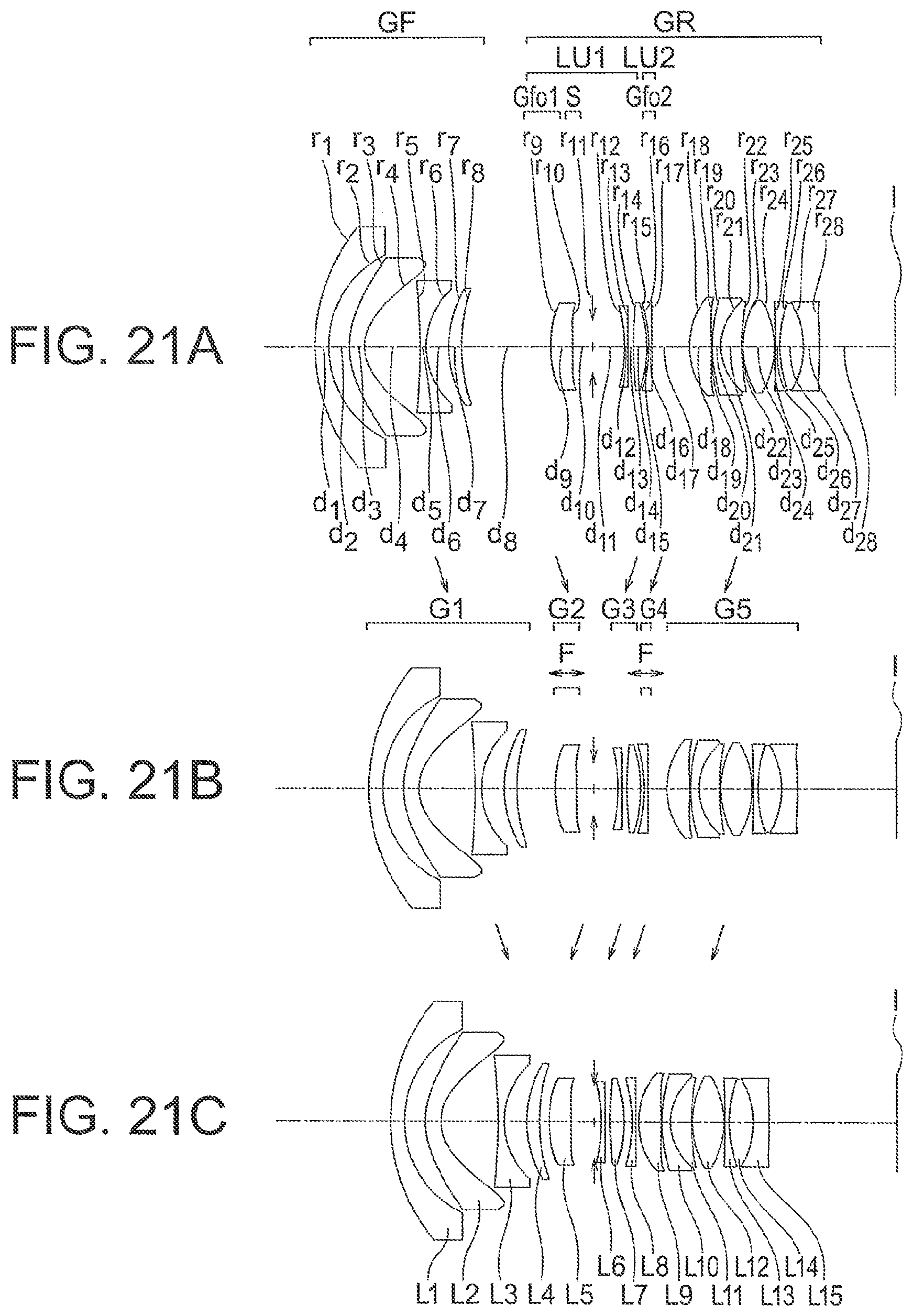
D00022

D00023

D00024

D00025

D00026

D00027

D00028

D00029
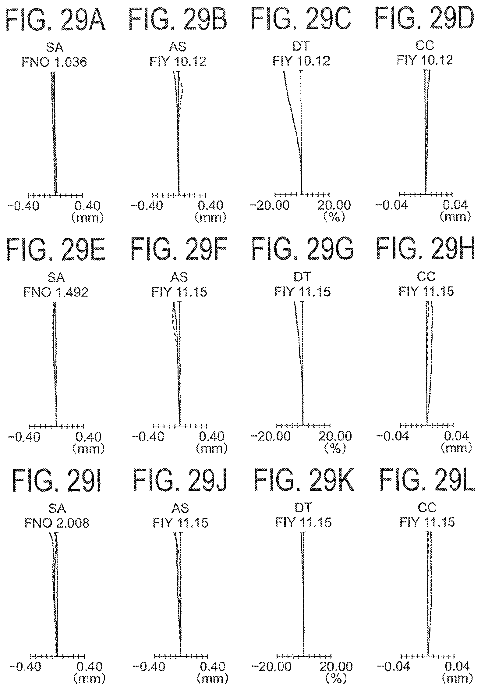
D00030

D00031

D00032

D00033

D00034

D00035

D00036

D00037

D00038

D00039
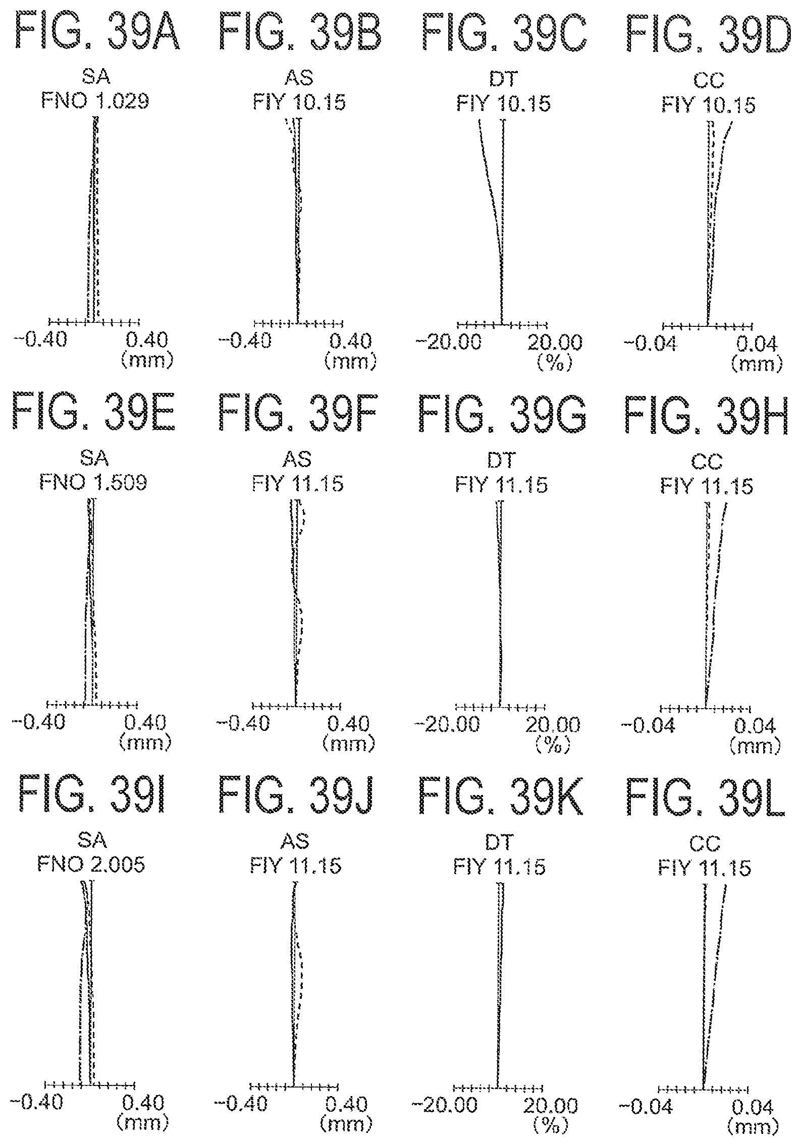
D00040

D00041

D00042

D00043

D00044
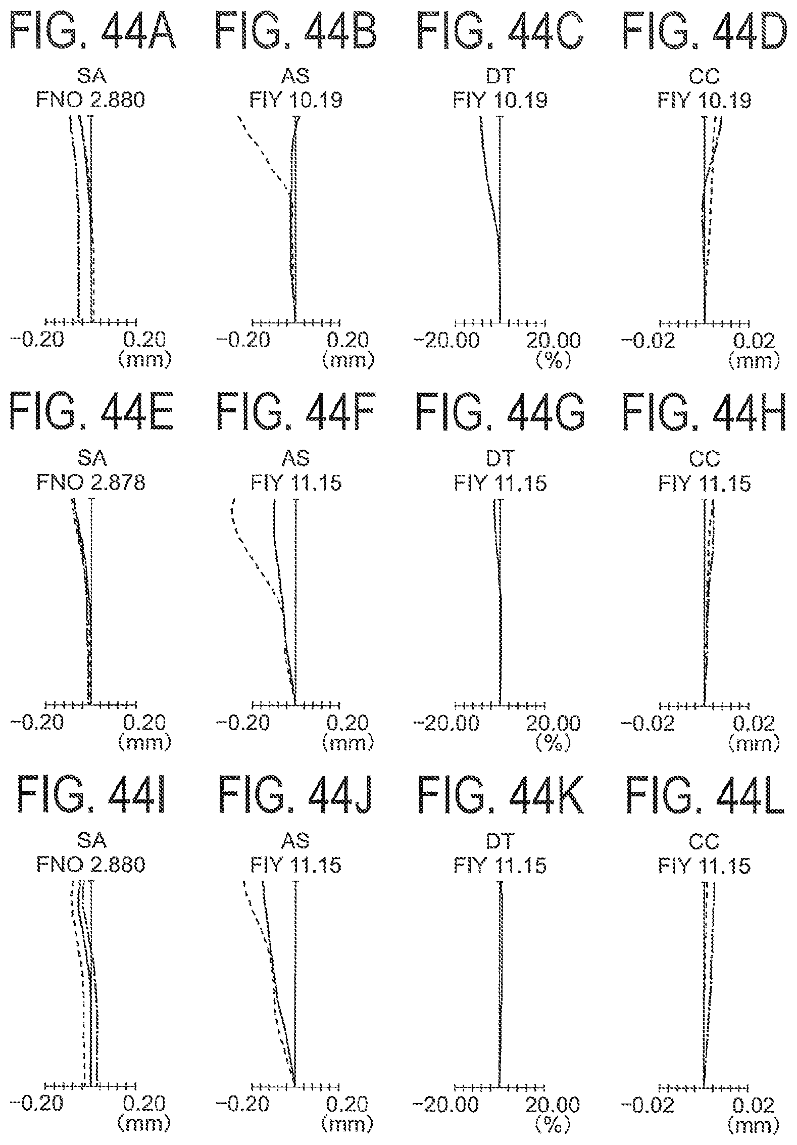
D00045
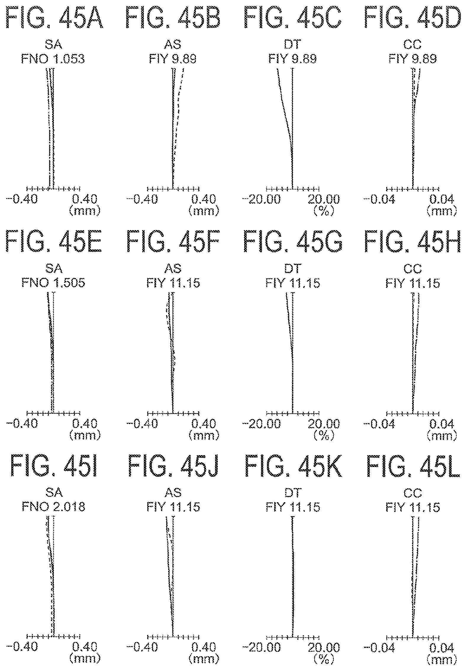
D00046

D00047

D00048

D00049

D00050

D00051

D00052

D00053

D00054
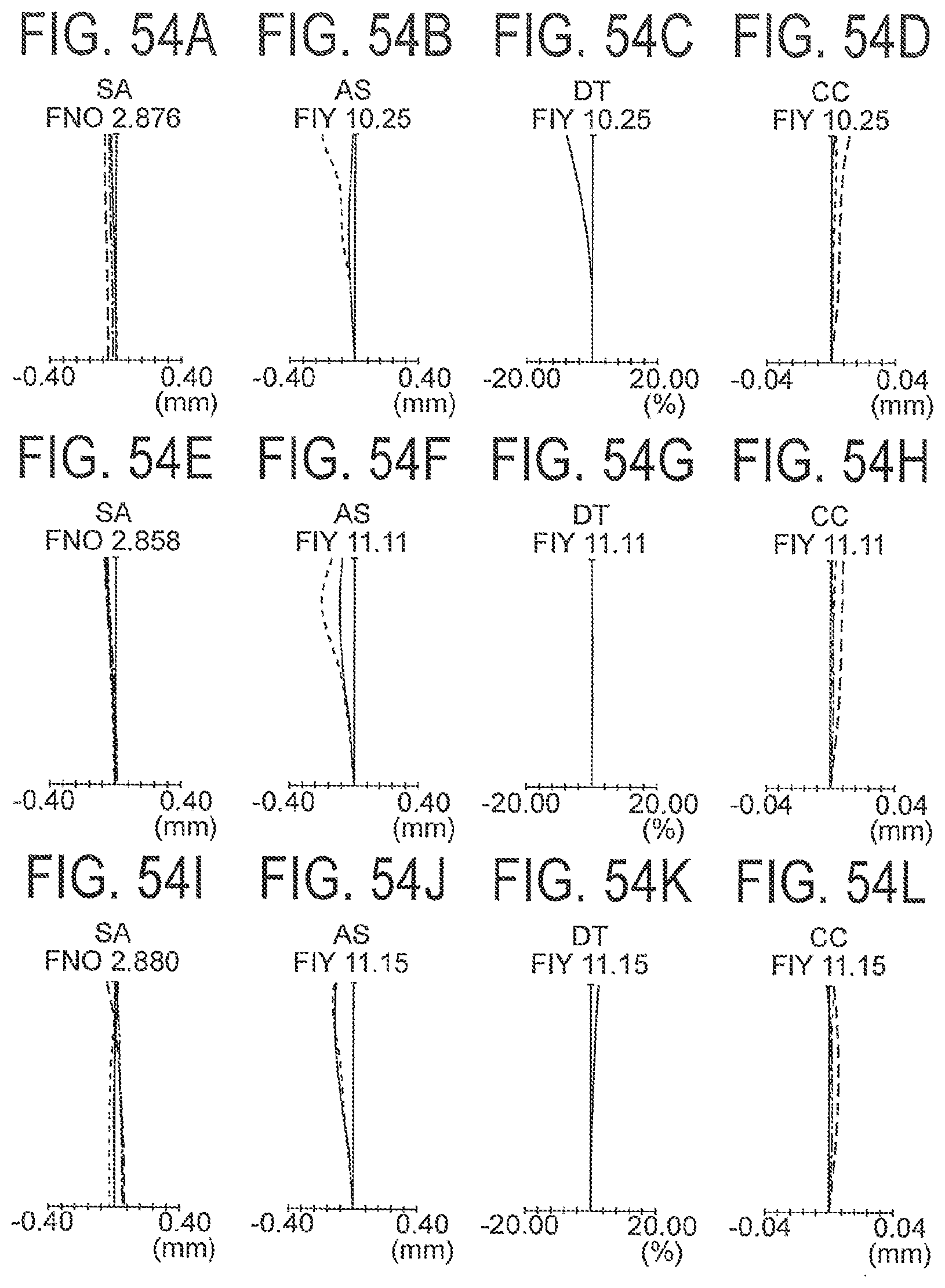
D00055

D00056

D00057

D00058
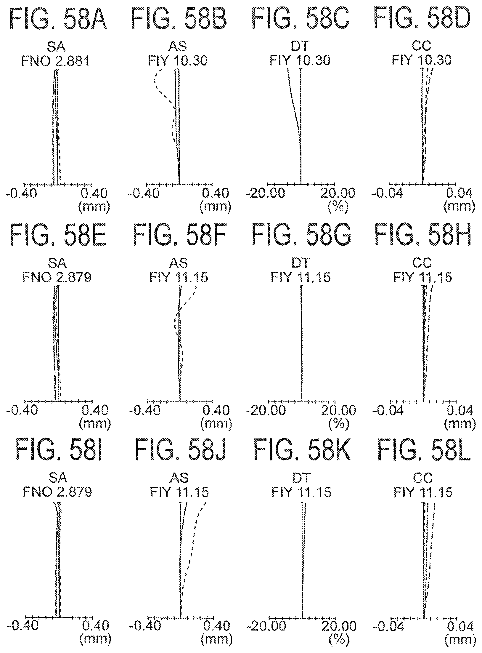
D00059

D00060

D00061

D00062

D00063

D00064

D00065
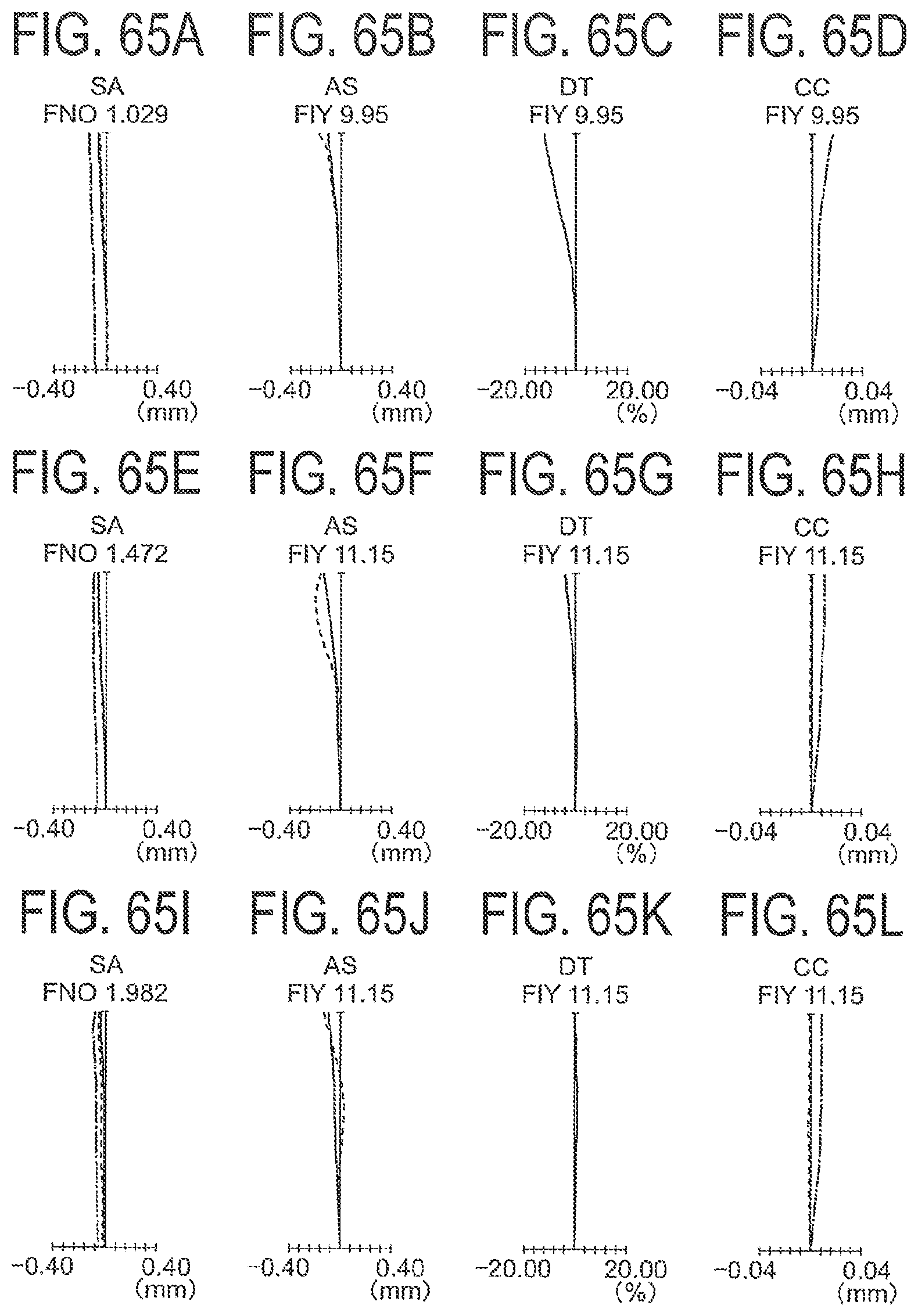
D00066
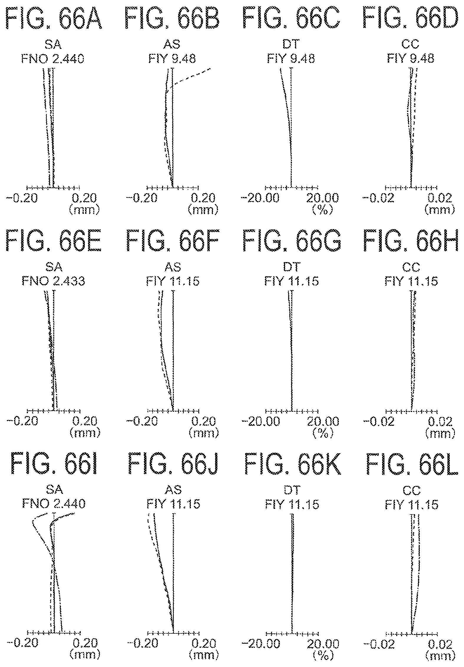
D00067

D00068

D00069
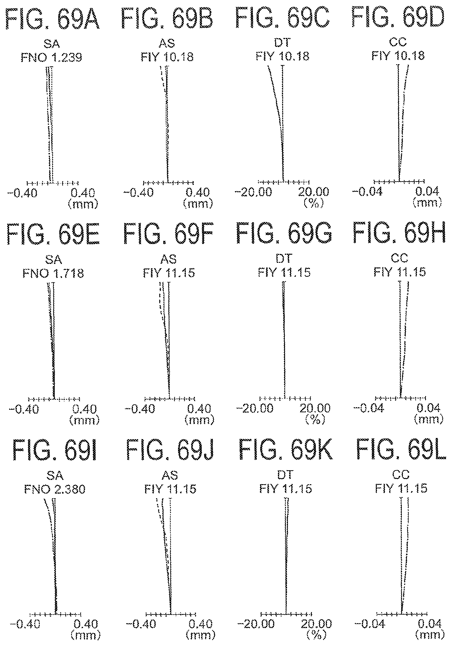
D00070

D00071

D00072

D00073

D00074

D00075

D00076

D00077

D00078

D00079

XML
uspto.report is an independent third-party trademark research tool that is not affiliated, endorsed, or sponsored by the United States Patent and Trademark Office (USPTO) or any other governmental organization. The information provided by uspto.report is based on publicly available data at the time of writing and is intended for informational purposes only.
While we strive to provide accurate and up-to-date information, we do not guarantee the accuracy, completeness, reliability, or suitability of the information displayed on this site. The use of this site is at your own risk. Any reliance you place on such information is therefore strictly at your own risk.
All official trademark data, including owner information, should be verified by visiting the official USPTO website at www.uspto.gov. This site is not intended to replace professional legal advice and should not be used as a substitute for consulting with a legal professional who is knowledgeable about trademark law.