Method to predict pore pressure and seal integrity using full wavefield inversion
Lee , et al. Sep
U.S. patent number 10,768,324 [Application Number 15/485,395] was granted by the patent office on 2020-09-08 for method to predict pore pressure and seal integrity using full wavefield inversion. This patent grant is currently assigned to ExxonMobil Upstream Research Company. The grantee listed for this patent is Stan Lee, Prajnajyoti Mazumdar, Ratnanabha Sain. Invention is credited to Stan Lee, Prajnajyoti Mazumdar, Ratnanabha Sain.

View All Diagrams
| United States Patent | 10,768,324 |
| Lee , et al. | September 8, 2020 |
Method to predict pore pressure and seal integrity using full wavefield inversion
Abstract
A method, including: generating a velocity model for a subsurface region of the Earth by using a full wavefield inversion process; generating an impedance model for the subsurface region of the Earth by using a full wavefield inversion process; and estimating pore pressure at a prediction site in the subsurface region by integrating the velocity model and the impedance model with a velocity-based pore pressure estimation process.
| Inventors: | Lee; Stan (Spring, TX), Mazumdar; Prajnajyoti (Cypress, TX), Sain; Ratnanabha (Houston, TX) | ||||||||||
|---|---|---|---|---|---|---|---|---|---|---|---|
| Applicant: |
|
||||||||||
| Assignee: | ExxonMobil Upstream Research
Company (Spring, TX) |
||||||||||
| Family ID: | 1000005042299 | ||||||||||
| Appl. No.: | 15/485,395 | ||||||||||
| Filed: | April 12, 2017 |
Prior Publication Data
| Document Identifier | Publication Date | |
|---|---|---|
| US 20170335675 A1 | Nov 23, 2017 | |
Related U.S. Patent Documents
| Application Number | Filing Date | Patent Number | Issue Date | ||
|---|---|---|---|---|---|
| 62338799 | May 19, 2016 | ||||
| Current U.S. Class: | 1/1 |
| Current CPC Class: | G01V 1/303 (20130101); G01V 1/306 (20130101); G01V 1/282 (20130101); G01V 2210/614 (20130101) |
| Current International Class: | G01V 1/30 (20060101); G01V 1/28 (20060101) |
References Cited [Referenced By]
U.S. Patent Documents
| 3812457 | May 1974 | Weller |
| 3864667 | February 1975 | Bahjat |
| 4159463 | June 1979 | Silverman |
| 4168485 | September 1979 | Payton et al. |
| 4545039 | October 1985 | Savit |
| 4562650 | January 1986 | Nagasawa et al. |
| 4575830 | March 1986 | Ingram et al. |
| 4594662 | June 1986 | Devaney |
| 4636957 | January 1987 | Vannier et al. |
| 4675851 | June 1987 | Savit et al. |
| 4686654 | August 1987 | Savit |
| 4707812 | November 1987 | Martinez |
| 4715020 | December 1987 | Landrum, Jr. |
| 4766574 | August 1988 | Whitmore et al. |
| 4780856 | October 1988 | Becquey |
| 4823326 | April 1989 | Ward |
| 4924390 | May 1990 | Parsons et al. |
| 4953657 | September 1990 | Edington |
| 4969129 | November 1990 | Currie |
| 4982374 | January 1991 | Edington et al. |
| 5260911 | November 1993 | Mason et al. |
| 5469062 | November 1995 | Meyer, Jr. |
| 5583825 | December 1996 | Carrazzone et al. |
| 5677893 | October 1997 | de Hoop et al. |
| 5715213 | February 1998 | Allen |
| 5717655 | February 1998 | Beasley |
| 5719821 | February 1998 | Sallas et al. |
| 5721710 | February 1998 | Sallas et al. |
| 5790473 | August 1998 | Allen |
| 5798982 | August 1998 | He et al. |
| 5822269 | October 1998 | Allen |
| 5838634 | November 1998 | Jones et al. |
| 5852588 | December 1998 | de Hoop et al. |
| 5878372 | March 1999 | Tabarovsky et al. |
| 5920838 | July 1999 | Norris et al. |
| 5924049 | July 1999 | Beasley et al. |
| 5999488 | December 1999 | Smith |
| 5999489 | December 1999 | Lazaratos |
| 6014342 | January 2000 | Lazaratos |
| 6021094 | February 2000 | Ober et al. |
| 6028818 | February 2000 | Jeffryes |
| 6058073 | May 2000 | VerWest |
| 6125330 | September 2000 | Robertson et al. |
| 6219621 | April 2001 | Hornbostel |
| 6225803 | May 2001 | Chen |
| 6311133 | October 2001 | Lailly et al. |
| 6317695 | November 2001 | Zhou et al. |
| 6327537 | December 2001 | Ikelle |
| 6374201 | April 2002 | Grizon et al. |
| 6381543 | April 2002 | Guerillot et al. |
| 6388947 | May 2002 | Washbourne et al. |
| 6480790 | November 2002 | Calvert et al. |
| 6522973 | February 2003 | Tonellot et al. |
| 6545944 | April 2003 | de Kok |
| 6549854 | April 2003 | Malinverno et al. |
| 6574564 | June 2003 | Lailly et al. |
| 6593746 | July 2003 | Stolarczyk |
| 6662147 | December 2003 | Fournier et al. |
| 6665615 | December 2003 | Van Riel et al. |
| 6687619 | February 2004 | Moerig et al. |
| 6687659 | February 2004 | Shen |
| 6704245 | March 2004 | Becquey |
| 6714867 | March 2004 | Meunier |
| 6735527 | May 2004 | Levin |
| 6754590 | June 2004 | Moldoveanu |
| 6766256 | July 2004 | Jeffryes |
| 6826486 | November 2004 | Malinverno |
| 6836448 | December 2004 | Robertsson et al. |
| 6842701 | January 2005 | Moerig et al. |
| 6859734 | February 2005 | Bednar |
| 6865487 | March 2005 | Charron |
| 6865488 | March 2005 | Moerig et al. |
| 6876928 | April 2005 | Van Riel et al. |
| 6882938 | April 2005 | Vaage et al. |
| 6882958 | April 2005 | Schmidt et al. |
| 6901333 | May 2005 | Van Riel et al. |
| 6903999 | June 2005 | Curtis et al. |
| 6905916 | June 2005 | Bartsch et al. |
| 6906981 | June 2005 | Vauge |
| 6927698 | August 2005 | Stolarczyk |
| 6944546 | September 2005 | Xiao et al. |
| 6947843 | September 2005 | Fisher et al. |
| 6970397 | November 2005 | Castagna et al. |
| 6977866 | December 2005 | Huffman et al. |
| 6999880 | February 2006 | Lee |
| 7027927 | April 2006 | Matsuoka et al. |
| 7046581 | May 2006 | Calvert |
| 7050356 | May 2006 | Jeffryes |
| 7069149 | June 2006 | Goff et al. |
| 7072767 | July 2006 | Routh et al. |
| 7092823 | August 2006 | Lailly et al. |
| 7110900 | September 2006 | Adler et al. |
| 7184367 | February 2007 | Yin |
| 7230879 | June 2007 | Herkenhoff et al. |
| 7271747 | September 2007 | Baraniuk et al. |
| 7330799 | February 2008 | Lefebvre et al. |
| 7337069 | February 2008 | Masson et al. |
| 7373251 | May 2008 | Hamman et al. |
| 7373252 | May 2008 | Sherrill et al. |
| 7376046 | May 2008 | Jeffryes |
| 7376539 | May 2008 | Lecomte |
| 7400978 | July 2008 | Langlais et al. |
| 7436734 | October 2008 | Krohn |
| 7480206 | January 2009 | Hill |
| 7584056 | September 2009 | Koren |
| 7599798 | October 2009 | Beasley et al. |
| 7602670 | October 2009 | Jeffryes |
| 7616523 | November 2009 | Tabti et al. |
| 7620534 | November 2009 | Pita et al. |
| 7620536 | November 2009 | Chow |
| 7646924 | January 2010 | Donoho |
| 7672194 | March 2010 | Jeffryes |
| 7672824 | March 2010 | Dutta et al. |
| 7675815 | March 2010 | Saenger et al. |
| 7679990 | March 2010 | Herkenhoff et al. |
| 7684281 | March 2010 | Vaage et al. |
| 7710821 | May 2010 | Robertsson et al. |
| 7715985 | May 2010 | Van Manen et al. |
| 7715986 | May 2010 | Nemeth et al. |
| 7725266 | May 2010 | Sirgue et al. |
| 7791980 | September 2010 | Robertsson et al. |
| 7835072 | November 2010 | Izumi |
| 7840625 | November 2010 | Candes et al. |
| 7940601 | May 2011 | Ghosh |
| 8121823 | February 2012 | Krebs et al. |
| 8248886 | August 2012 | Neelamani et al. |
| 8428925 | April 2013 | Krebs et al. |
| 8437998 | May 2013 | Routh |
| 8547794 | October 2013 | Gulati et al. |
| 8682587 | March 2014 | Singer |
| 8688381 | April 2014 | Routh et al. |
| 8781748 | July 2014 | Laddoch et al. |
| 9310500 | April 2016 | Kacewicz |
| 9841518 | December 2017 | Aarre |
| 10386513 | August 2019 | Aarre |
| 2002/0049540 | April 2002 | Beve et al. |
| 2002/0099504 | July 2002 | Cross et al. |
| 2002/0120429 | August 2002 | Ortoleva |
| 2002/0183980 | December 2002 | Guillaume |
| 2004/0199330 | October 2004 | Routh et al. |
| 2004/0225438 | November 2004 | Okoniewski et al. |
| 2006/0235666 | October 2006 | Assa et al. |
| 2007/0036030 | February 2007 | Baumel et al. |
| 2007/0038691 | February 2007 | Candes et al. |
| 2007/0274155 | November 2007 | Ikelle |
| 2008/0175101 | July 2008 | Saenger et al. |
| 2008/0306692 | December 2008 | Singer et al. |
| 2009/0006054 | January 2009 | Song |
| 2009/0067041 | March 2009 | Krauklis et al. |
| 2009/0070042 | March 2009 | Birchwood et al. |
| 2009/0083006 | March 2009 | Mackie |
| 2009/0164186 | June 2009 | Haase et al. |
| 2009/0164756 | June 2009 | Dokken et al. |
| 2009/0187391 | July 2009 | Wendt et al. |
| 2009/0248308 | October 2009 | Luling |
| 2009/0254320 | October 2009 | Lovatini et al. |
| 2009/0259406 | October 2009 | Khadhraoui et al. |
| 2010/0008184 | January 2010 | Hegna et al. |
| 2010/0018718 | January 2010 | Krebs et al. |
| 2010/0039894 | February 2010 | Abma et al. |
| 2010/0054082 | March 2010 | McGarry et al. |
| 2010/0088035 | April 2010 | Etgen et al. |
| 2010/0103772 | April 2010 | Eick et al. |
| 2010/0118651 | May 2010 | Liu et al. |
| 2010/0142316 | June 2010 | Keers et al. |
| 2010/0161233 | June 2010 | Saenger et al. |
| 2010/0161234 | June 2010 | Saenger et al. |
| 2010/0185422 | July 2010 | Hoversten |
| 2010/0208554 | August 2010 | Chiu et al. |
| 2010/0212902 | August 2010 | Baumstein et al. |
| 2010/0246324 | September 2010 | Dragoset, Jr. et al. |
| 2010/0265797 | October 2010 | Robertsson et al. |
| 2010/0270026 | October 2010 | Lazaratos et al. |
| 2010/0286919 | November 2010 | Lee et al. |
| 2010/0299070 | November 2010 | Abma |
| 2011/0000678 | January 2011 | Krebs et al. |
| 2011/0040926 | February 2011 | Donderici et al. |
| 2011/0051553 | March 2011 | Scott et al. |
| 2011/0075516 | March 2011 | Xia et al. |
| 2011/0090760 | April 2011 | Rickett et al. |
| 2011/0131020 | June 2011 | Meng |
| 2011/0134722 | June 2011 | Virgilio et al. |
| 2011/0182141 | July 2011 | Zhamikov et al. |
| 2011/0182144 | July 2011 | Gray |
| 2011/0191032 | August 2011 | Moore |
| 2011/0194379 | August 2011 | Lee et al. |
| 2011/0222370 | September 2011 | Downton et al. |
| 2011/0227577 | September 2011 | Zhang et al. |
| 2011/0235464 | September 2011 | Brittan et al. |
| 2011/0238390 | September 2011 | Krebs et al. |
| 2011/0246140 | October 2011 | Abubakar et al. |
| 2011/0267921 | November 2011 | Mortel et al. |
| 2011/0267923 | November 2011 | Shin |
| 2011/0276320 | November 2011 | Krebs et al. |
| 2011/0288831 | November 2011 | Tan et al. |
| 2011/0299361 | December 2011 | Shin |
| 2011/0320180 | December 2011 | Al-Saleh |
| 2012/0010862 | January 2012 | Costen |
| 2012/0014215 | January 2012 | Saenger et al. |
| 2012/0014216 | January 2012 | Saenger et al. |
| 2012/0051176 | March 2012 | Liu |
| 2012/0073824 | March 2012 | Routh |
| 2012/0073825 | March 2012 | Routh |
| 2012/0082344 | April 2012 | Donoho |
| 2012/0143506 | June 2012 | Routh et al. |
| 2012/0215506 | August 2012 | Rickett et al. |
| 2012/0218859 | August 2012 | Soubaras |
| 2012/0275264 | November 2012 | Kostov et al. |
| 2012/0275267 | November 2012 | Neelamani et al. |
| 2012/0290214 | November 2012 | Huo et al. |
| 2390712 | Jan 2004 | GB | |||
| 2006037815 | Apr 2006 | WO | |||
| 2009067041 | May 2009 | WO | |||
| 2010085822 | Jul 2010 | WO | |||
| 2011040926 | Apr 2011 | WO | |||
| 2011091216 | Jul 2011 | WO | |||
| 2011093945 | Aug 2011 | WO | |||
| 2012024025 | Feb 2012 | WO | |||
| 2012041834 | Apr 2012 | WO | |||
| 2012083234 | Jun 2012 | WO | |||
| 2012134621 | Oct 2012 | WO | |||
| 2012170201 | Dec 2012 | WO | |||
| 2013081752 | Jun 2013 | WO | |||
Other References
|
Soleymani, Hamidreza, and Mohamad-Ali Riahi. "Velocity based pore pressure prediction--A case study at one of the Iranian southwest oil fields." Journal of Petroleum Science and Engineering 94 (2012): 40-46. cited by examiner . Wang, Jie, Hui Zhou, Yukun Tian, and Hongjing Zhang. "A new scheme for elastic full waveform inversion based on velocity-stress wave equations in time domain." In SEG Technical Program Expanded Abstracts 2012, pp. 1-5. Society of Exploration Geophysicists, 2012. cited by examiner . Tang, Yaxun, Sunwoong Lee, Anatoly Baumstein, and Dave Hinkley. "Tomographically enhanced full wavefield inversion." In SEG Technical Program Expanded Abstracts 2013, pp. 1037-1041. Society of Exploration Geophysicists, 2013. cited by examiner . Wang, Zi. "Target formation pore-pressure prediction using 3D seismic data via the Fillippone and Eaton approaches in southern Sichuan, China." PhD diss., 2014. cited by examiner . Gao, H. et al. (2008), "Implementation of perfectly matched layers in an arbitrary geometrical boundary for leastic wave modeling," Geophysics J. Int. 174, pp. 1029-1036. cited by applicant . Gibson, B. et al. (1984), "Predictive deconvolution and the zero-phase source," Geophysics 49(4), pp. 379-397. cited by applicant . Godfrey, R. J. et al. (1998), "Imaging the Foiaven Ghost," SEG Expanded Abstracts, 4 pgs. cited by applicant . Griewank, A. (1992), "Achieving logarithmic growth of temporal and spatial complexity in reverse automatic differentiation," 1 Optimization Methods and Software, pp. 35-54. cited by applicant . Griewank, A. (2000), Evaluating Derivatives: Principles and Techniques of Algorithmic Differentiation, Society for Industrial and Applied Mathematics, 49 pgs. cited by applicant . Griewank, A. et al. (2000), "Algorithm 799: An implementation of checkpointing for the reverse or adjoint mode of computational differentiation," 26 ACM Transactions on Mathematical Software, pp. 19-45. cited by applicant . Griewank, A. et al. (1996), "Algorithm 755: A package for the automatic differentiation of algorithms written in C/C++," ACM Transactions on Mathematical 22(2), pp. 131-167. cited by applicant . Haber, E. et al. (2010), "An effective method for parameter estimation with PDE constraints with multiple right hand sides," Preprint--UBC http://www.math.ubc.ca/.about.haber/pubs/PdeOptStochV5.pdf. cited by applicant . Hampson, D.P. et al. (2005), "Simultaneous inversion of pre-stack seismic data," SEG 75.sup.th Annual Int'l. Meeting, Expanded Abstracts, pp. 1633-1637. cited by applicant . Heinkenschloss, M. (2008), :"Numerical Solution of Implicity Constrained Optimization Problems," CAAM Technical Report TR08-05, 25 pgs. cited by applicant . Helbig, K. (1994), "Foundations of Anisotropy for Exploration Seismics," Chapter 5, pp. 185-194. cited by applicant . Herrmann, F.J. (2010), "Randomized dimensionality reduction for full-waveform inversion," EAGE abstract G001, EAGE Barcelona meeting, 5 pgs. cited by applicant . Holschneider, J. et al. (2005), "Characterization of dispersive surface waves using continuous wavelet transforms," Geophys. J. Int. 163, pp. 463-478. cited by applicant . Hu, L.Z. et al. (1987), "Wave-field transformations of vertical seismic profiles," Geophysics 52, pp. 307-321. cited by applicant . Huang, Y. et al. (2012), "Multisource least-squares migration of marine streamer and land data with frequency-division encoding," Geophysical Prospecting 60, pp. 663-680. cited by applicant . Igel, H. et al. (1996), "Waveform inversion of marine reflection seismograms for P impedance and Poisson's ratio," Geophys. J. Int 124, pp. 363-371. cited by applicant . Ikelle, L.T. (2007), "Coding and decoding: Seismic data modeling, acquisition, and processing," 77th Annual Int'l. Meeting, SEG Expanded Abstracts, pp. 66-70. cited by applicant . Jackson, D.R. et al. (1991), "Phase conjugation in underwater acoustics," J. Acoust. Soc. Am. 89(1), pp. 171-181. cited by applicant . Jing, X. et al. (2000), "Encoding multiple shot gathers in prestack migration," SEG International Exposition and 70.sup.th Annual Meeting Expanded Abstracts, pp. 786-789. cited by applicant . Kennett, B.L.N. (1991), "The removal of free surface interactions from three-component seismograms", Geophys. J. Int. 104, pp. 153-163. cited by applicant . Kennett, B.L.N. et al. (1988), "Subspace methods for large inverse problems with multiple parameter classes," Geophysical J. 94, pp. 237-247. cited by applicant . Krebs, J.R. (2008), "Fast Full-wavefield seismic inversion using encoded sources," Geophysics 74(6), pp. WCC177-WCC188. cited by applicant . Krohn, C.E. (1984), "Geophone ground coupling," Geophysics 49(6), pp. 722-731. cited by applicant . Kroode, F.T. et al. (2009), "Wave Equation Based Model Building and Imaging in Complex Settings," OTC 20215, 2009 Offshore Technology Conf., Houston, TX, May 4-7, 2009, 8 pgs. cited by applicant . Kulesh, M. et al. (2008), "Modeling of Wave Dispersion Using Continuous Wavelet Transforms II: Wavelet-based Frequency-velocity Analysis," Pure Applied Geophysics 165, pp. 255-270. cited by applicant . Lancaster, S. et al. (2000), "Fast-track `colored` inversion," 70.sup.th SEG .Ann. Meeting, Expanded Abstracts, pp. 1572-1575. cited by applicant . Lazaratos, S. et al. (2009), "Inversion of Pre-migration Spectral Shaping," 2009 SEG Houston Int'l. Expo. & Ann. Meeting, Expanded Abstracts, pp. 2383-2387. cited by applicant . Lazaratos, S. (2006), "Spectral Shaping Inversion for Elastic and Rock Property Estimation," Research Disclosure, Issue 511, pp. 1453-1459. cited by applicant . Lazaratos, S. et al. (2011), "Improving the convergence rate of full wavefield inversion using spectral shaping," SEG Expanded Abstracts 30, pp. 2428-2432. cited by applicant . Lecomte, I. (2008), "Resolution and illumination analyses in PSDM: A ray-based approach," The Leading Edge, pp. 650-663. cited by applicant . Lee, S. et al. (2010), "Subsurface parameter estimation in full wavefield inversion and reverse time migration," SEG Denver 2010 Annual Meeting, pp. 1065-1069. cited by applicant . Levanon, N. (1988), "Radar Principles," Chpt. 1, John Whiley & Sons, New York, pp. 1-18. cited by applicant . Liao, Q. et al. (1995), "2.5D full-wavefield viscoacoustic inversion," Geophysical Prospecting 43, pp. 1043-1059. cited by applicant . Liu, F. et al. (2007), "Reverse-time migration using one-way wavefield imaging condition," SEG Expanded Abstracts 26, pp. 2170-2174. cited by applicant . Liu, F. et al. (2011), "An effective imaging condition for reverse-time migration using wavefield decomposition," Geophysics 76, pp. S29-S39. cited by applicant . Maharramov, M. et al. (2007) , "Localized image-difference wave-equation tomography," SEG Annual Meeting, Expanded Abstracts, pp. 3009-3013. cited by applicant . Malmedy, V. et al. (2009), "Approximating Hessians in unconstrained optimization arising from discretized problems," Computational Optimization and Applications, pp. 1-16. cited by applicant . Marcinkovich, C. et al. (2003), "On the implementation of perfectly matched layers in a three-dimensional fourth-order velocity-stress finite difference scheme," J. of Geophysical Research 108(B5), 2276. cited by applicant . Martin, G.S. et al. (2006), "Marmousi2: An elastic upgrade for Marmousi," The Leading Edge, pp. 156-166. cited by applicant . Meier, M.A. et al. (2009), "Converted wave resolution," Geophysics, 74(2):doi:10.1190/1.3074303, pp. Q1-Q16. cited by applicant . Moghaddam, P.P. et al. (2010), "Randomized full-waveform inversion: a dimenstionality-reduction approach," 80.sup.th SEG Ann. Meeting, Expanded Abstracts, pp. 977-982. cited by applicant . Mora, P. (1987), "Nonlinear two-dimensional elastic inversion of multi-offset seismic data," Geophysics 52, pp. 1211-1228. cited by applicant . Abt, D.L. et al. (2010), "North American lithospheric discontinuity structured imaged by Ps and Sp receiver functions", J. Geophys. Res., 24 pgs. cited by applicant . Akerberg, P., et al. (2008), "Simultaneous source separation by sparse radon transform," 78th SEG Annual International Meeting, Expanded Abstracts, pp. 2801-2805. cited by applicant . Aki, K. et al. (1980), "Quantitative Seismology: Theory and Methods Volume I--Chapter 7--Surface Waves in a Vertically Heterogenous Medium," W.H. Freeman and Co., pp. 259-318. cited by applicant . Aki, K. et al. (1980), "Quantitative Seismology: Theory and Methods Volume I," W.H. Freeman and Co., p. 173. cited by applicant . Aki et al. (1980), "Quantitative Seismology, Theory and Methods," Chapter 5.20, W.H. Freeman & Co., pp. 133-155. cited by applicant . Amundsen, L. (2001), "Elimination of free-surface related multiples without need of the source wavelet," Geophysics 60(1), pp. 327-341. cited by applicant . Anderson, J.E. et al. (2008), "Sources Near the Free-Surface Boundary: Pitfalls for Elastic Finite-Difference Seismic Simulation and Multi-Grid Waveform Inversion," 70.sup.th EAGE Conf. & Exh., 4 pgs. cited by applicant . Barr, F.J. et al. (1989), "Attenuation of Water-Column Reverberations Using Pressure and Velocity Detectors in a Water-Bottom Cable," 59.sup.th Annual SEG meeting, Expanded Abstracts, pp. 653-656. cited by applicant . Baumstein, A. et al. (2009), "Scaling of the Objective Function Gradient for Full Wavefield Inversion," SEG Houston 2009 Int'l. Expo and Annual Meeting, pp. 224-2247. cited by applicant . Beasley, C. (2008), "A new look at marine simultaneous sources," The Leading Edge 27(7), pp. 914-917. cited by applicant . Beasley, C. (2012), "A 3D simultaneous source field test processed using alternating projections: a new active separation method," Geophsyical Prospecting 60, pp. 591-601. cited by applicant . Beaty, K.S. et al. (2003), "Repeatability of multimode Rayleigh-wave dispersion studies," Geophysics 68(3), pp. 782-790. cited by applicant . Beaty, K.S. et al. (2002), "Simulated annealing inversion of multimode Rayleigh wave dispersion waves for geological structure," Geophys. J. Int. 151, pp. 622-631. cited by applicant . Becquey, M. et al. (2002), "Pseudo-Random Coded Simultaneous Vibroseismics," SEG Int'l. Exposition and 72th Annl. Mtg., 4 pgs. cited by applicant . Ben-Hadj-Ali, H. et al. (2009), "Three-dimensional frequency-domain full waveform inversion with phase encoding," SEG Expanded Abstracts, pp. 2288-2292. cited by applicant . Ben-Hadj-Ali, H. et al. (2011), "An efficient frequency-domain full waveform inversion method using simultaneous encoded sources," Geophysics 76(4), pp. R109-R124. cited by applicant . Benitez, D. et al. (2001), "The use of the Hilbert transform in ECG signal analysis," Computers in Biology and Medicine 31, pp. 399-406. cited by applicant . Berenger, J-P. (1994), "A Perfectly Matched Layer for the Absorption of Electromagnetic Waves," J. of Computational Physics 114, pp. 185-200. cited by applicant . Berkhout, A.J. (1987), "Applied Seismic Wave Theory," Elsevier Science Publishers, p. 142. cited by applicant . Berkhout, A.J. (1992), "Areal shot record technology," Journal of Seismic Exploration 1, pp. 251-264. cited by applicant . Berkhout, A.J. (2008), "Changing the mindset in seismic data acquisition," The Leading Edge27(7), pp. 924-938. cited by applicant . Beylkin, G. (1985), "Imaging of discontinuities in the inverse scattring problem by inversion of a causal generalized Radon transform," J. Math. Phys. 26, pp. 99-108. cited by applicant . Biondi, B. (1992), "Velocity estimation by beam stack," Geophysics 57(8), pp. 1034-1047. cited by applicant . Bonomi, E. et al. (2006), "Wavefield Migration plus Monte Carlo Imaging of 3D Prestack Seismic Data," Geophysical Prospecting 54, pp. 505-514. cited by applicant . Boonyasiriwat, C. et al. (2010), 3D Multisource Full-Waveform using Dynamic Random Phase Encoding, SEG Denver 2010 Annual Meeting, pp. 1044-1049. cited by applicant . Boonyasiriwat, C. et al. (2010), 3D Multisource Full-Waveform using Dynamic Random Phase Encoding, SEG Denver 2010 Annual Meeting, pp. 3120-3124. cited by applicant . Bunks, C., et al. (1995), "Multiscale seismic waveform inversion," Geophysics 60, pp. 1457-1473. cited by applicant . Burstedde, G. et al. (2009), "Algorithmic strategies for full waveform inversion: 1D experiments," Geophysics 74(6), pp. WCC17-WCC46. cited by applicant . Chavent, G. et al. (1999), "An optimal true-amplitude least-squares prestack depth-migration operator," Geophysics 64(2), pp. 508-515. cited by applicant . Choi, Y. et al. (2011), "Application of encoded multisource waveform inversion to marine-streamer acquisition based on the global correlation," 73.sup.rd EAGE Conference, Abstract, pp. F026. cited by applicant . Choi, Y et al. (2012), "Application of multi-source waveform inversion to marine stream data using the global correlation norm," Geophysical Prospecting 60, pp. 748-758. cited by applicant . Clapp, R.G. (2009), "Reverse time migration with random boundaries," SEG International Exposition and Meeting, Expanded Abstracts, pp. 2809-2813. cited by applicant . Dai, W. et al. (2010), "3D Multi-source Least-squares Reverse Time Migration," SEG Denver 2010 Annual Meeting, pp. 3120-3124. cited by applicant . Delprat-Jannuad, F et al. (2005), "A fundamental limitation for the reconstruction of impedance profiles from seismic data," Geophysics 70(1), pp. R1-R14. cited by applicant . Dickens, T.A. et al. (2011), RTM angle gathers using Poynting vectors, SEG Expanded Abstracts 30, pp. 3109-3113. cited by applicant . Donerici, B. et al. (1005), "Improved FDTD Subgridding Algorithms Via Digital Filtering and Domain Overriding," IEEE Transactions on Antennas and Propagation 53(9), pp. 2938-2951. cited by applicant . Downey, N. et al. (2011), "Random-Beam Full-Wavefield Inversion," 2011 San Antonio Annual Meeting, pp. 2423-2427. cited by applicant . Dunkin, J.W. et al. (1973), "Effect of Normal Moveout on a Seismic Pluse," Geophysics 38(4), pp. 635-642. cited by applicant . Dziewonski A. et al. (1981), "Preliminary Reference Earth Model", Phys. Earth Planet. Int. 25(4), pp. 297-356. cited by applicant . Ernst, F.E. et al. (2000), "Tomography of dispersive media," J. Acoust. Soc. Am 108(1), pp. 105-116. cited by applicant . Ernst, F.E. et al. (2002), "Removal of scattered guided waves from seismic data," Geophysics 67(4), pp. 1240-1248. cited by applicant . Esmersoy, C. (1990), "Inversion of P And SV waves from multicomponent offset vertical seismic profiles", Geophysics 55(1), pp. 39-50. cited by applicant . Etgen, J.T. et al. (2007), "Computational methods for large-scale 3D acoustic finite-difference modeling: A tutorial," Geophysics 72(5), pp. SM223-SM230. cited by applicant . Fallat, M.R. et al. (1999), "Geoacoustic inversion via local, global, and hybrid algorithms," Journal of the Acoustical Society of America 105, pp. 3219-3230. cited by applicant . Fichtner, A. et al. (2006), "The adjoint method in seismology I. Theory," Physics of the Earth and Planetary Interiors 157, pp. 86-104. cited by applicant . Forbriger, T. (2003), "Inversion of shallow-seismic wavefields: I. Wavefield transformation," Geophys. J. Int. 153, pp. 719-734. cited by applicant. |
Primary Examiner: Perveen; Rehana
Assistant Examiner: Luu; Cuong V
Attorney, Agent or Firm: ExxonMobil Upstream Research Company--Law Department
Parent Case Text
CROSS-REFERENCE TO RELATED APPLICATION
This application claims the benefit of U.S. Provisional Patent Application 62/338,799 filed May 19, 2016 entitled METHOD TO PREDICT PORE PRESSURE AND SEAL INTEGRITY USING FULL WAVEFIELD INVERSION, the entirety of which is incorporated by reference herein.
Claims
What is claimed is:
1. A method, comprising: generating a velocity model for a subsurface region of the Earth by using one or more full wavefield inversion processes; generating an impedance model for the subsurface region of the Earth by using one or more full wavefield inversion processes; estimating pore pressure at a prediction site in the subsurface region by integrating the velocity model and the impedance model with a velocity-based pore pressure estimation process, wherein the prediction site includes a reservoir rock, and wherein the velocity-based pore pressure estimation process comprises: identifying, within the impedance model, the reservoir rock; using the velocity model to determine or estimate shale pore pressure at a base of the reservoir rock in the impedance model; determining a buoyancy pressure of a fluid assumed to fill a column height of the reservoir rock; and the estimating the pore pressure for the reservoir rock includes combining the shale pore pressure at the base of the reservoir rock and the buoyancy pressure; charactering a mechanical seal integrity of the subsurface region using the estimated pore pressure; and managing hydrocarbons in the subsurface region using the estimated pore pressure and mechanical seal integrity.
2. The method of claim 1, further comprising: predicting a lithology volume for the subsurface geologic formation from the impedance model; determining Poisson's ratio within the reservoir rock based on the lithology volume and P-wave velocity from the velocity model generated using the full wavefield inversion process; and determining a full wavefield inversion lithology-based minimum horizontal stress from the Poisson's ratio.
3. The method of claim 2, further comprising: analyzing seal integrity of the reservoir rock based on a difference between the estimated pore pressure and the minimum horizontal stress.
4. The method of claim 3, wherein the reservoir rock is sand.
5. The method of claim 2, wherein the predicting the lithology volume includes using impedance values from an offset well.
6. The method of claim 1, wherein the fluid is one of oil, gas, or water.
7. The method of claim 1, wherein managing hydrocarbons comprises extracting hydrocarbons from the reservoir rock.
Description
FIELD OF THE INVENTION
Exemplary embodiments described herein pertain generally to the field of geophysical prospecting, and more particularly to geophysical data processing. More specifically, an exemplary embodiment can predict subsurface pore pressure and characterize seal integrity.
BACKGROUND
This section is intended to introduce various aspects of the art, which may be associated with exemplary embodiments of the present invention. This discussion is believed to assist in providing a framework to facilitate a better understanding of particular aspects of the present invention. Accordingly, it should be understood that this section should be read in this light, and not necessarily as admissions of prior art.
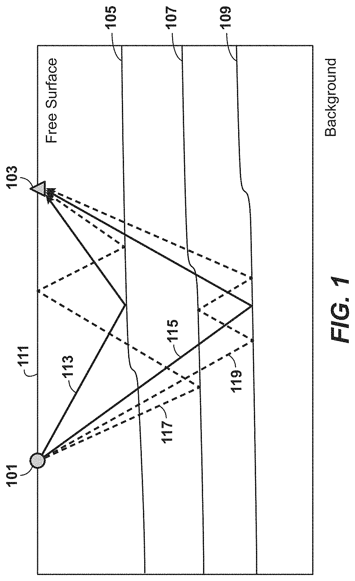
Seismic inversion is a process of extracting information about the subsurface from data measured at the surface of the Earth during a seismic acquisition survey. In a typical seismic survey, seismic waves are generated by a source 101 positioned at a desired location. As the source generated waves propagate through the subsurface, some of the energy reflects from subsurface interfaces 105, 107, and 109 and travels back to the surface 111, where it is recorded by the receivers 103. The seismic waves 113 and 115 that have been reflected in the subsurface only once before reaching the recording devices are called primary reflections. In contrast, multiple reflections 117 and 119 are the seismic waves that have reflected multiple times along their travel path back to the surface. Surface-related multiple reflections are the waves that have reflected multiple times and incorporate the surface of the Earth or the water surface in their travel path before being recorded.
Full Wavefield Inversion (FWI) is a seismic method capable of utilizing the full seismic record, including the seismic events that are treated as "noise" by standard inversion algorithms. The goal of FWI is to build a realistic subsurface model by minimizing the misfit between the recorded seismic data and synthetic (or modeled) data obtained via numerical simulation.
FWI is a computer-implemented geophysical method that is used to invert for subsurface properties such as velocity or acoustic impedance. The crux of any FWI algorithm can be described as follows: using a starting subsurface physical property model, synthetic seismic data are generated, i.e. modeled or simulated, by solving the wave equation using a numerical scheme (e.g., finite-difference, finite-element etc.). The term velocity model or physical property model as used herein refers to an array of numbers, typically a 3-D array, where each number, which may be called a model parameter, is a value of velocity or another physical property in a cell, where a subsurface region has been conceptually divided into discrete cells for computational purposes. The synthetic seismic data are compared with the field seismic data and using the difference between the two, an error or objective function is calculated. Using the objective function, a modified subsurface model is generated which is used to simulate a new set of synthetic seismic data. This new set of synthetic seismic data is compared with the field data to generate a new objective function. This process is repeated until the objective function is satisfactorily minimized and the final subsurface model is generated. A global or local optimization method is used to minimize the objective function and to update the subsurface model.
The exploration and production industry is moving into frontier oil and gas provinces with higher well costs and drilling risks. In order to execute a drilling program in a safe, efficient and cost effective manner, accurate pre-drill prediction of pore pressure and fracture pressure is useful. In addition, seal integrity analysis is useful in understanding how much hydrocarbons can be trapped by prospect seals before mechanical leak. Conventionally, these analyses have been done using seismic velocities obtained from tomography. Tomographic velocities are used to predict pore pressure using Eaton's normal compaction trend and Bower's effective stress methods. In general, such velocity profiles are suitable for pore pressure prediction in background shales, but are too smooth to detect embedded sand reservoirs. In comparison, FWI provides higher resolution and more accurate velocity models, which provides an opportunity to do pressure prediction for the sands as well. Pressure prediction for sands allows for the appraisal of mechanical seal failure risks of overlying shales.
SUMMARY
A method, including: generating a velocity model for a subsurface region of the Earth by using a full wavefield inversion process; generating an impedance model for the subsurface region of the Earth by using a full wavefield inversion process; and estimating pore pressure at a prediction site in the subsurface region by integrating the velocity model and the impedance model with a velocity-based pore pressure estimation process.
In the method, the prediction site can include a reservoir rock, and the velocity-based pore pressure estimation process can include: identifying, within the impedance model, the reservoir rock; using the velocity model to determine or estimate shale pore pressure at a base of the reservoir rock in the impedance model; determining a buoyancy pressure of a fluid assumed to fill a column height of the reservoir rock; and the estimating the pore pressure for the reservoir rock can include combining the shale pore pressure at the base of the reservoir rock and the buoyancy pressure.
The method can further include: predicting a lithology volume for the subsurface geologic formation from the impedance model; determining Poisson's ratio within the reservoir rock based on the lithology volume and P-wave velocity from the velocity model generated using the full wavefield inversion process; and determining a full wavefield inversion lithology-based minimum horizontal stress from the Poisson's ratio.
The method can further include: analyzing seal integrity of the reservoir rock based on a difference between the estimated pore pressure and the minimum horizontal stress.
In the method, the reservoir rock can be sand.
In the method, the predicting the lithology volume can include using impedance values from an offset well.
In the method, the fluid can be one of oil, gas, or water.
The method can further include extracting hydrocarbons from the reservoir rock.
BRIEF DESCRIPTION OF THE DRAWINGS
While the present disclosure is susceptible to various modifications and alternative forms, specific example embodiments thereof have been shown in the drawings and are herein described in detail. It should be understood, however, that the description herein of specific example embodiments is not intended to limit the disclosure to the particular forms disclosed herein, but on the contrary, this disclosure is to cover all modifications and equivalents as defined by the appended claims. It should also be understood that the drawings are not necessarily to scale, emphasis instead being placed upon clearly illustrating principles of exemplary embodiments of the present invention. Moreover, certain dimensions may be exaggerated to help visually convey such principles.
FIG. 1 illustrates an example of a conventional seismic acquisition.
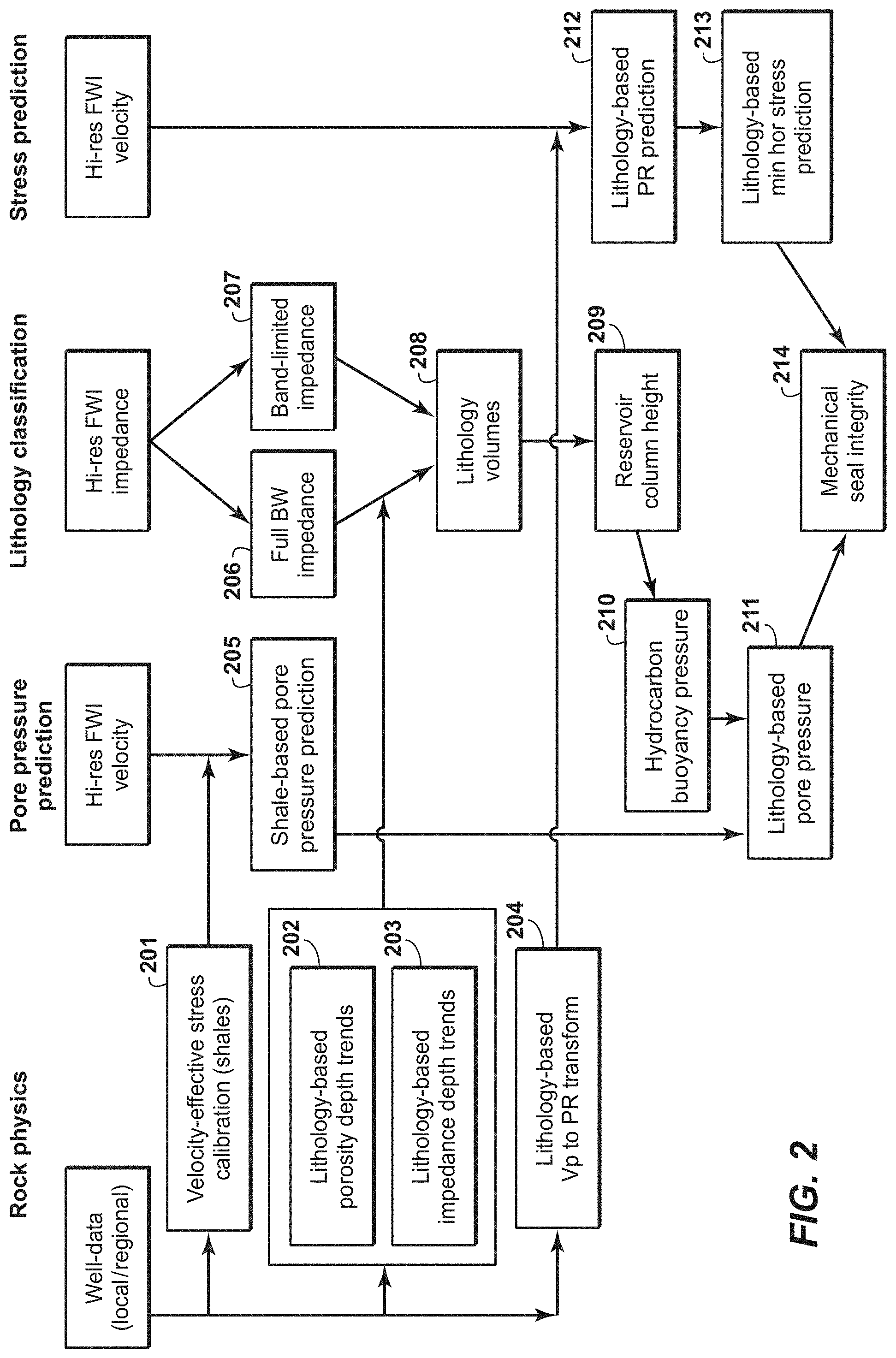
FIG. 2 illustrates an exemplary method for predicting pore pressure and seal integrity.
FIG. 3 illustrates an exemplary plot of velocity vs. effective stress.
FIG. 4 illustrates an exemplary plot of porosity vs. depth.
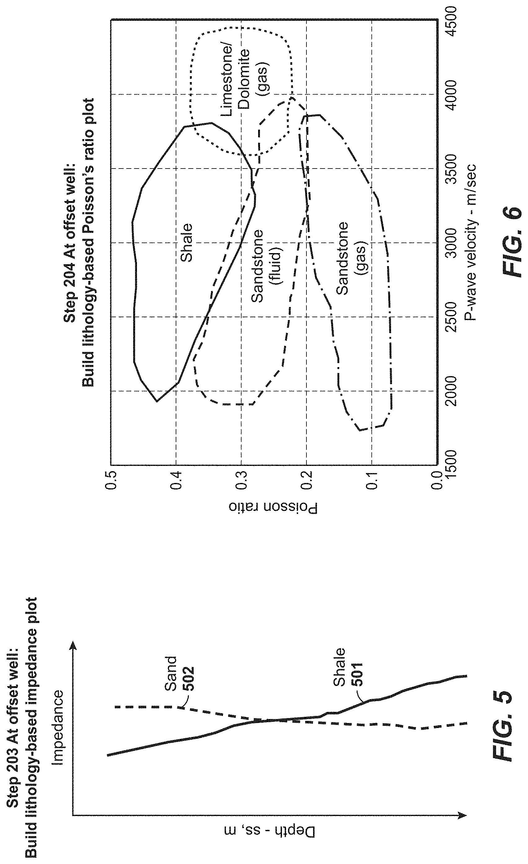
FIG. 5 illustrates an exemplary plot of impedance vs. depth.
FIG. 6 illustrates an exemplary Poisson's ratio cross-plot.
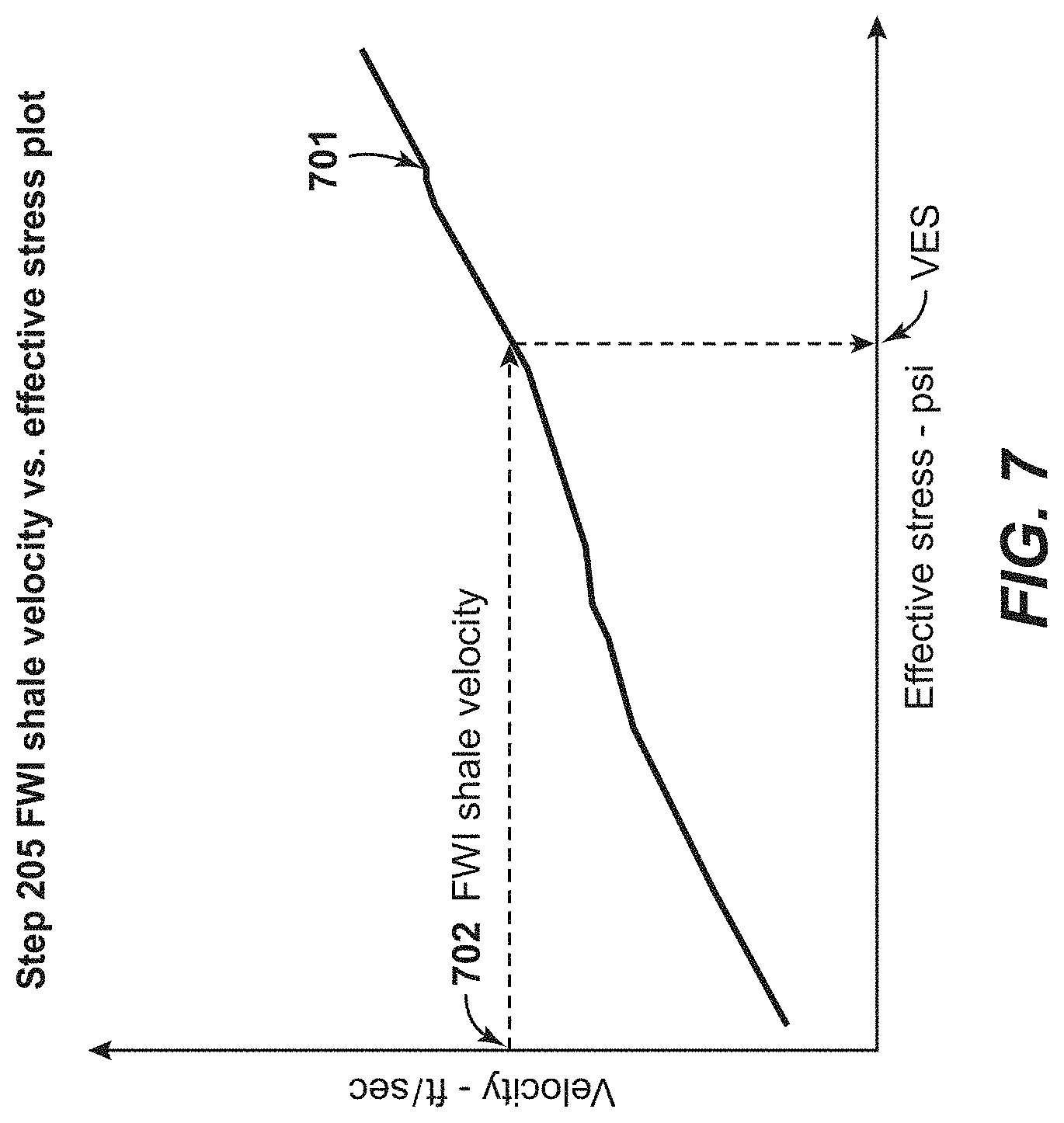
FIG. 7 illustrates an exemplary plot of velocity vs effective stress from FWI shale velocity.
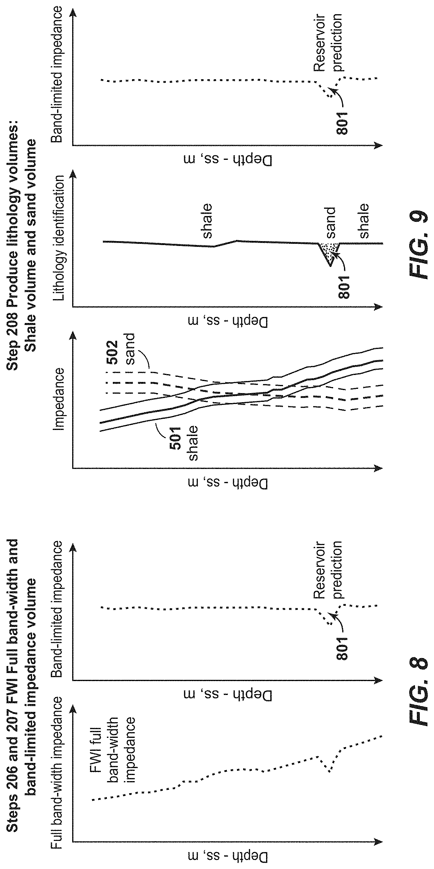
FIG. 8 illustrates an exemplary plot of impedance vs. depth from FWI full bandwidth impedance and FWI band limited impedance.
FIG. 9 illustrates an exemplary plot of Vclay vs. depth.
FIG. 10 illustrates an exemplary FWI derived lithology sand volume.
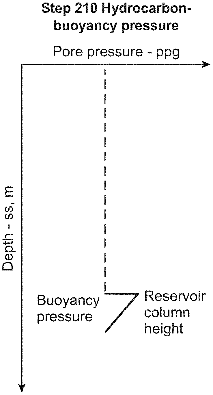
FIG. 11 illustrates an exemplary buoyancy pressure determination.
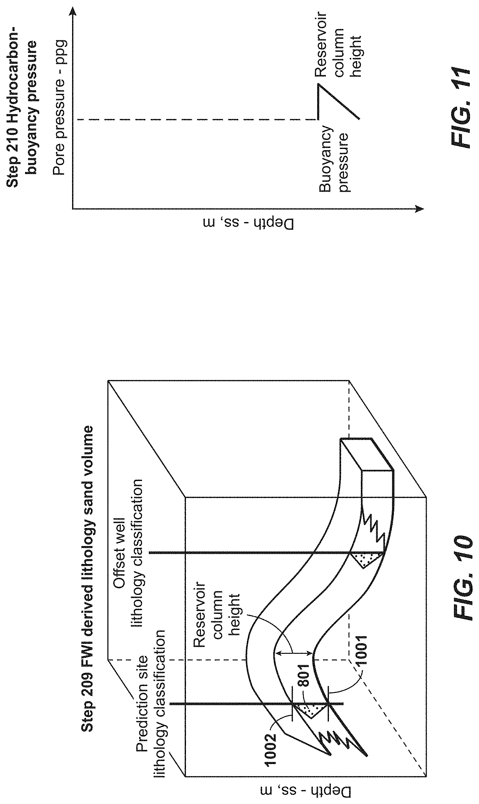
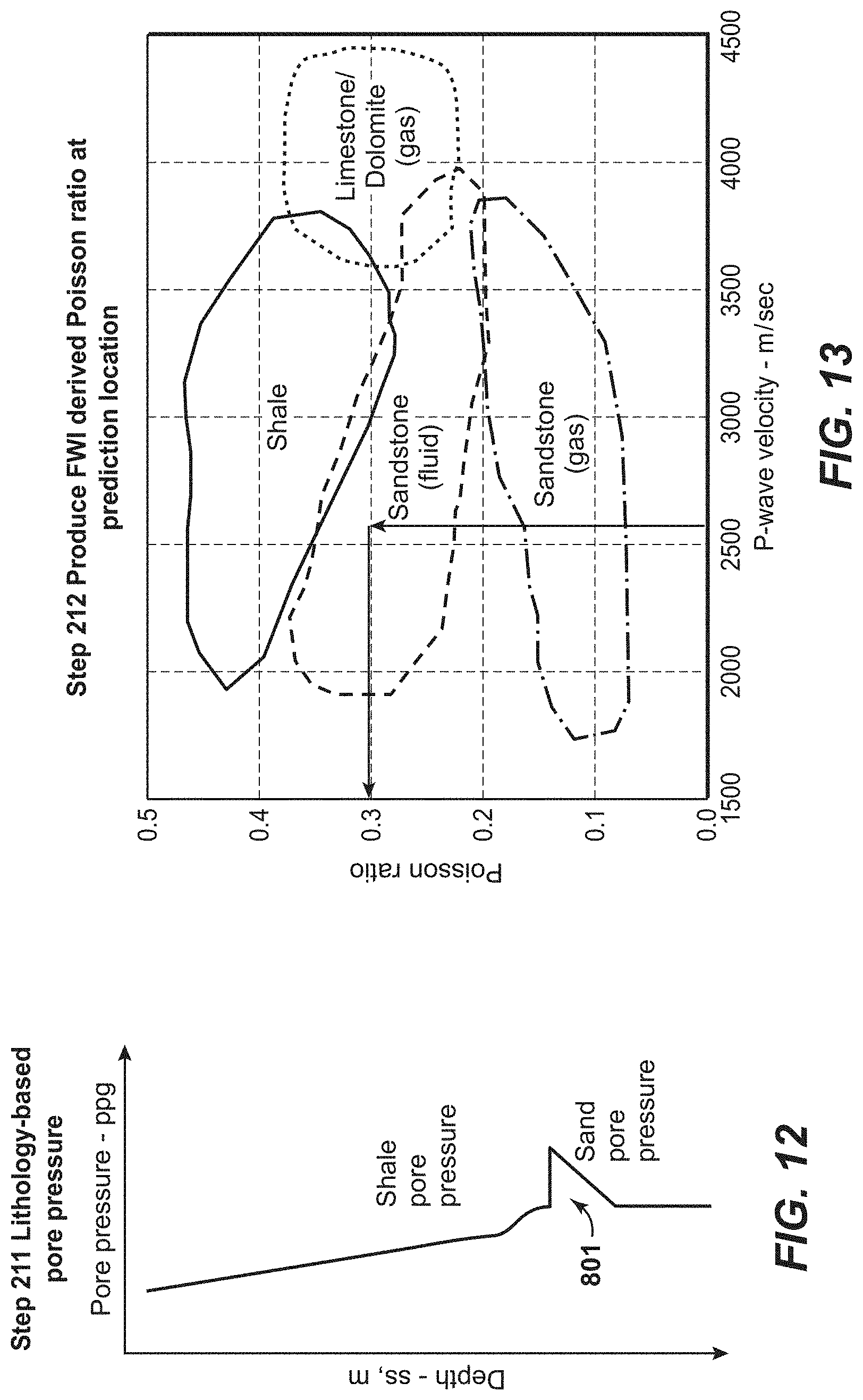
FIG. 12 illustrates an exemplary plot of pore pressure vs. depth for lithology based pore pressure.
FIG. 13 illustrates an exemplary derivation of FWI derived Poisson's ratio at a predicted location.
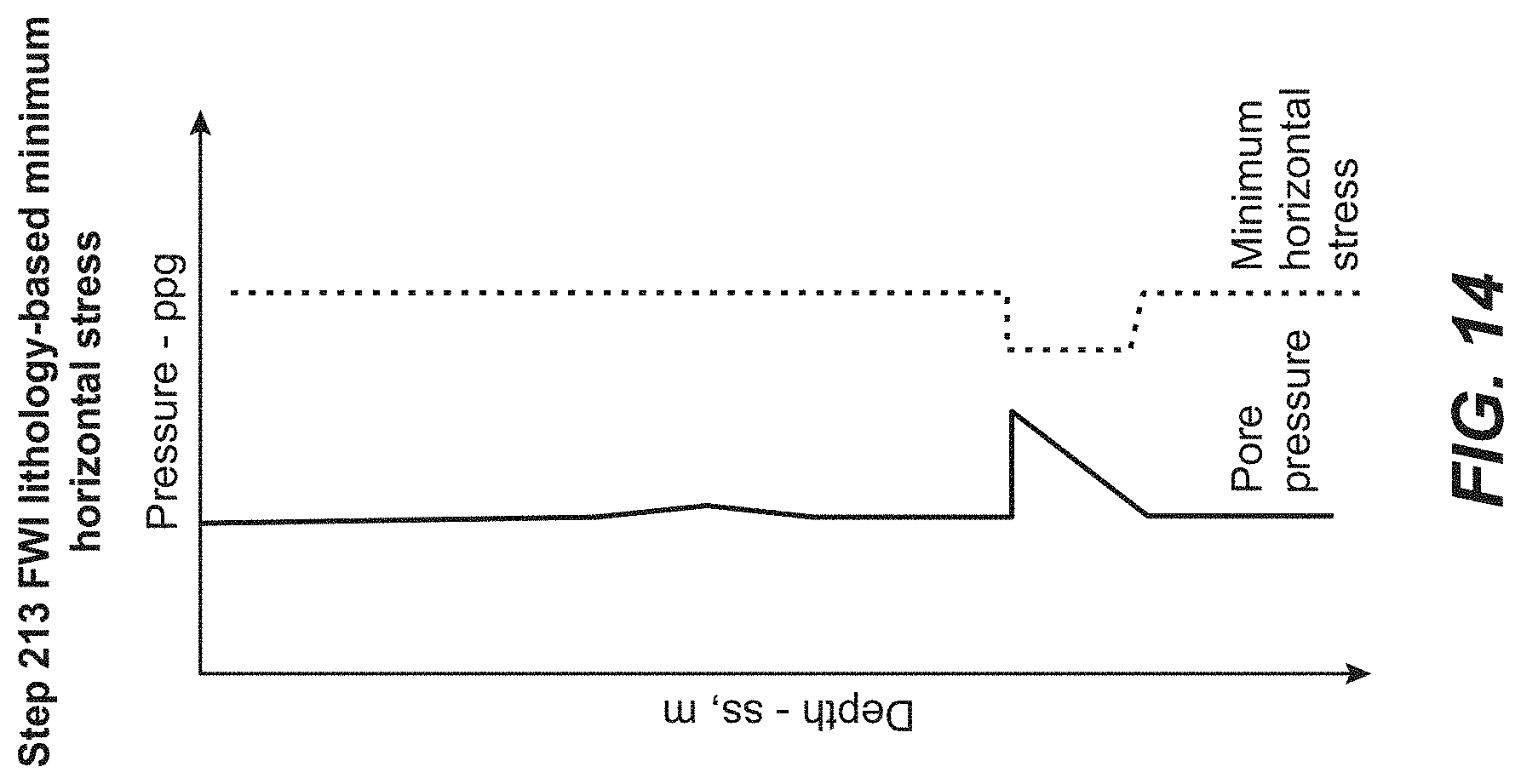
FIG. 14 illustrates an exemplary plot of minimum horizontal stress vs. depth for FWI lithology-based minimum horizontal stress.
DETAILED DESCRIPTION
Exemplary embodiments are described herein. However, to the extent that the following description is specific to a particular embodiment, this is intended to be for exemplary purposes only and simply provides a description of the exemplary embodiments. Accordingly, the invention is not limited to the specific embodiments described below, but rather, it includes all alternatives, modifications, and equivalents falling within the true spirit and scope of the appended claims.
In recent years, FWI has been widely used in industry and academia to improve seismic imaging quality (Mothi, et al., 2012; Liu et al., 2014), particularly for regions with significant structural complexity. The present technological advancement can improve prediction of subsurface pore pressure estimates and can characterize seal integrity. In a non-limiting example, subsurface pore-pressure can be predicted using higher resolution and more accurate FWI velocity models (as compared to tomographic velocity) in conjunction with conventional effective stress methods. Lithology inversions can be integrated from high-resolution model domain (FWI impedance) products with velocity-based pore pressure estimation. The coupled analysis allows for the reduction in uncertainty in pressure prediction due to lithology (primarily, sand vs. shale, but other reservoir rock could be used in place of sand) changes. Further, pressure prediction in sand allows for preparation for seal integrity analysis. The results from the integrated lithology inversion can be used to appraise the risk of mechanical seal failure, given fluid-fill (or hydrocarbon type) and fluid-column height scenarios. Fracture pressure or minimum stress in the seals can be predicted by using either a constant fracture gradient measured from regional or global leak off test (LOT) databases or through geomechanical method-based estimations (viz., stress-ratio equations).
Inputs for the present technological advancement include: (1) FWI model domain products (velocity and impedance); and (2) rock physics transformations for lithology classification, velocity pressure relations and lithology-based Poisson's ratio estimation.
Compared to conventional techniques, the present technological advancement can use higher resolution (.about.0-15 Hz) velocities from FWI instead of lower resolution tomographic velocities, uses lithology (sand vs. shale)--dependent pressure-velocity relations for estimating pore-pressure from FWI P-velocity inversion instead of using a single pressure-velocity relation, and uses data-driven seal strength from seismic methods to analyze seal integrity instead of using spatially continuous or homogenous seal properties.
FIG. 2 illustrates an exemplary method for predicting pore pressure and seal integrity. Step 201 includes building a shale-velocity vs. effective stress plot (see FIG. 3) for an offset well. Offset well density and pressure data can be used to calculate overburden pressure from density logs. As shown below in equation 1, effective stress is equal to overburden pressure minus pore pressure. Effective Stress=Overburden Pressure-pore pressure (Eqn. 1)
Pore pressure can be either obtained by direct measurement in the field or estimated from drilling mud weight. Sand pore pressure is usually obtained from the direct measurement in the reservoir. Shale pore pressure can be measured in the formation or estimated from drilling parameters and well events.
Step 202 includes building a lithology based porosity plot for an offset well (see FIG. 4). Offset well log data and core analyses can be used to build a shale porosity vs. depth compaction trend 401 and a sand porosity vs. depth compaction trend 402 (see FIG. 4).
Step 203 includes building a lithology-based impedance plot (see FIG. 5). Offset well velocity and density are used to obtain acoustic impedance by multiplying velocity and density. As shown in FIG. 5, a shale acoustic impedance vs. depth trend 501 is generated and a sand acoustic impedance vs. depth trend 502 is generated.
Step 204 includes building a lithology-based Poisson's ratio cross plot at an offset well (see, FIG. 6). The offset wells primary velocity (Vp) and secondary velocity (Vs) are used to calculate Poisson's ratio 6, as shown in equation 2. .sigma.=1/2(V.sub.P.sup.2-2V.sub.S.sup.2)/(V.sub.P.sup.2-V.sub.S.sup.2) (Eqn. 2) The cross-plot in FIG. 6 is generated based on the Poisson's ratio and P-wave velocity. (VES). Shale pore pressure at the prediction location can be obtained via equation 1.
Step 205 includes calculating the overburden pressure at the prediction location. The velocity vs. effective stress plot from step 201 is shown as 701 in FIG. 7, along with the FWI shale velocity 702, and FWI shale velocity is used to obtain the effective stress.
Step 206 includes generating high frequency FWI full bandwidth (BW) and band-limited impedance data using seismic shot gathers. The following is an example of an algorithm for performing local cost function optimization in FWI. This procedure is iterated by using the new updated model as the starting model for another gradient search. The process continues until an updated model is found that satisfactorily explains the observed data. Commonly used local cost function inversion methods include gradient search, conjugate gradients and Newton's method.
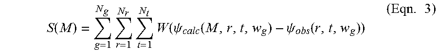
Local cost function optimization of seismic data in the acoustic approximation is a common geophysical inversion task, and is generally illustrative of other types of geophysical inversion. When inverting seismic data in the acoustic approximation the cost function can be written as:
.function..times..times..times..function..psi..function..psi..function..t- imes. ##EQU00001## where: S=cost function, M=vector of N parameters, (m.sub.1, m.sub.2, . . . m.sub.N) describing the subsurface model, g=gather index, w.sub.g=source function for gather g which is a function of spatial coordinates and time, for a point source this is a delta function of the spatial coordinates, N.sub.g=number of gathers, r=receiver index within gather, N.sub.r=number of receivers in a gather, t=time sample index within a trace, N.sub.t=number of time samples, W=minimization criteria function (a preferred choice is W(x)=x.sup.2, which is the least squares (L2) criteria), .psi..sub.calc=calculated seismic data from the model M, .psi..sub.obs=measured seismic data.
The gathers can be any type of gather that can be simulated in one run of a seismic forward modeling program. Usually the gathers correspond to a seismic shot, although the shots can be more general than point sources. For point sources the gather index g corresponds to the location of individual point sources. For plane wave sources g would correspond to different plane wave propagation directions. This generalized source data, .psi..sub.obs, can either be acquired in the field or can be synthesized from data acquired using point sources. The calculated data .psi..sub.calc on the other hand can usually be computed directly by using a generalized source function when forward modeling. For many types of forward modeling, including finite difference modeling, the computation time needed for a generalized source is roughly equal to the computation time needed for a point source.
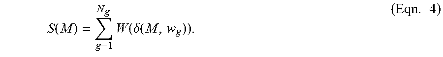
Equation (3) can be simplified to:
.function..times..function..delta..function..times. ##EQU00002## where the sum over receivers and time samples is now implied and, .delta.(M,w.sub.g)=.psi..sub.calc(M,w.sub.g)-.psi..sub.obs(w.sub.g). (Eqn. 5)
Inversion attempts to update the model M such that S(M) is a minimum. This can be accomplished by local cost function optimization which updates the given model M.sup.(k) as follows: M.sup.(k+1)=M.sup.(k)-.alpha..sup.(k).gradient..sub.MS(M) (Eqn. 6) where k is the iteration number, .alpha. is the scalar size of the model update, and .gradient..sub.MS(M) is the gradient of the misfit function, taken with respect to the model parameters. The model perturbations, or the values by which the model is updated, are calculated by multiplication of the gradient of the objective function with a step length a, which must be repeatedly calculated.
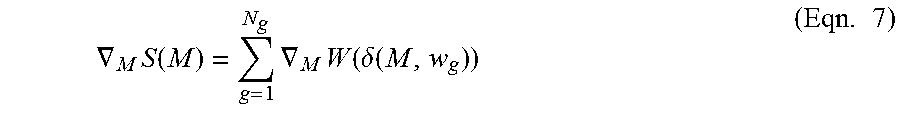
From equation (4), the following equation can be derived for the gradient of the cost function:
.gradient..times..function..times..gradient..times..function..delta..time- s..times. ##EQU00003##
So to compute the gradient of the cost function one must separately compute the gradient of each gather's contribution to the cost function, then sum those contributions. Therefore, the computational effort required for computing .gradient..sub.MS(M) is N.sub.g times the compute effort required to determine the contribution of a single gather to the gradient. For geophysical problems, N.sub.g usually corresponds to the number of geophysical sources and is on the order of 10,000 to 100,000, greatly magnifying the cost of computing .gradient..sub.MS(M).
Note that computation of .gradient..sub.MW(.delta.) requires computation of the derivative of W(.delta.) with respect to each of the N model parameters m.sub.1. Since for geophysical problems N is usually very large (usually more than one million), this computation can be extremely time consuming if it had to be performed for each individual model parameter. Fortunately, the adjoint method can be used to efficiently perform this computation for all model parameters at once. The adjoint method for the least squares objective function and a gridded model parameterization is summarized by the following algorithm:
1. Compute forward simulation of the data using the current model and the gather signature w.sub.g as the source to get .psi..sub.calc(M.sup.(k),w.sub.g),
2. Subtract the observed data from the simulated data giving .delta.(M.sup.(k),w.sub.g),
3. Compute the reverse simulation (i.e. backwards in time) using .delta.(M.sup.(k),w.sub.g) as the source producing .psi..sub.adjoint(M.sup.(k),w.sub.g),
4. Compute the integral over time of the product of .psi..sub.calc(M.sup.(k),w.sub.g) and .psi..sub.adjoint(M.sup.(k),w.sub.g) to get .gradient..sub.MW(.delta.(M,w.sub.g)).
Step 207 includes generating the FWI band limited impedance. The FWI band limited impedance is determined by: FWI Band Limited Impedance=FWI Full Bandwidth Impedance-Shale Impedance Trend. FIG. 8 shows a comparison of the FWI band-limited impedance and the FWI full bandwidth impedance. In FIG. 8, 801 identifies the reservoir prediction of an anomaly (i.e., a sand body). FWI is able to show the anomaly 801, whereas tomographic velocity would not.
Step 208 includes producing lithology volumes (shale volume and sand volume). FWI full bandwidth impedance minus shale impedance 501 is used to obtain shale lithology identification. FWI full bandwidth impedance minus sand impedance 502 is used to obtain sand lithology identification. FWI band-limited impedance is used to check the sand lithology classification and shale lithology classification when the curves 501 and 502 are off compaction trend. FIG. 9 shows lithology for shale and sand, including the sand anomaly 801.
Step 209 includes determining the reservoir column height. The FWI derived lithology from step 208 is used to determine reservoir and column heights. As indicated in FIG. 10, the FWI derived lithology from step 208 is consistent with offset well lithology log at an offset well location. At the new prediction location, FWI derived lithology is used to digitize the top 1002 of the sand body and base 1001 of the sand body 801. The column height of sand body 801 is the elevation between top of reservoir 1001 and the deepest portion of the entire reservoir body 1002.
In step 210, hydrocarbon buoyancy pressure is determined. Fluid is assumed to fill the column height of the sand body 801 (sand thickness). This is further illustrated in FIG. 11. The buoyancy pressure due to the existence of the fluid (gas/oil/water) in the sand body 801 is calculated. F.sub.b=g.rho.V=.rho.ghA (Eqn. 8) F.sub.b is the buoyant force, .rho. is the density of the fluid, g is gravity, V is the volume of the immersed part of the body in the fluid, h is the height of the immersed part, and A is the surface area of the immersed part. The fluid, whether gas, oil, or water, can be determined from amplitude vs offset (AVO) analysis or from data provided by the offset well.
In step 211, lithology-based pore pressure is predicted. This is determined from the shale pore pressure from step 205 and buoyancy pressure from step 210. At the prediction site, shale pore pressure is used as a background pore pressure. At the base of the sand body, the shale pore pressure will be used. The pressure within the sand is calculated from the sum of the fluid buoyancy pressure from step 210 and the base of shale pressure. This is further illustrated in FIG. 12.
Step 212 includes producing an FWI derived Poisson ratio (PR) at the prediction location (i.e., the sand anomaly 801). A high-resolution FWI velocity model, offset well lithology-based Poisson's ratio vs. velocity cross-plot from step 204 and lithology prediction from step 208 are used to predict the Poisson's ratio with the specific FWI P-wave velocity. This is further illustrated in FIG. 13.
Step 213 includes determining FWI lithology-based minimum horizontal stress. The minimum horizontal stress is determined from: Minimum horizontal stress=pore pressure+Ko*(overburden pressure-pore pressure)+tectonic term, (Eqn. 9) where the tectonic term is the lateral stress introduced by lateral movement of formation due to tectonic forces, and
.sigma..sigma. ##EQU00004## wherein .sigma. is Poisson's ratio, and a=constant that can be estimated from the offset well. The constant a can be obtained by matching offset well fracture pressure with calculated minimum horizontal stress using equation 9. FIG. 14 provides a comparison of the pore pressure and the minimum horizontal stress.
Step 214 includes obtaining the FWI derived mechanical seal integrity, which is calculated by the difference between the minimum horizontal stress and the pore pressure. As minimum horizontal stress gets closer to pore pressure, the mechanical seal will begin to fail. The values of mechanical seal integrity are close to zero.
Pore pressure predictions and mechanical seal integrity can be used to manage hydrocarbons. As used herein, hydrocarbon management includes hydrocarbon extraction, hydrocarbon production, hydrocarbon exploration, identifying potential hydrocarbon resources, identifying well locations, determining well injection and/or extraction rates, identifying reservoir connectivity, acquiring, disposing of and/or abandoning hydrocarbon resources, reviewing prior hydrocarbon management decisions, and any other hydrocarbon-related acts or activities.
In all practical applications, the present technological advancement must be used in conjunction with a computer, programmed in accordance with the disclosures herein. Preferably, in order to efficiently perform FWI, the computer is a high performance computer (HPC), known to those skilled in the art. Such high performance computers typically involve clusters of nodes, each node having multiple CPU's and computer memory that allow parallel computation. The models may be visualized and edited using any interactive visualization programs and associated hardware, such as monitors and projectors. The architecture of system may vary and may be composed of any number of suitable hardware structures capable of executing logical operations and displaying the output according to the present technological advancement. Those of ordinary skill in the art are aware of suitable supercomputers available from Cray or IBM.
The present techniques may be susceptible to various modifications and alternative forms, and the examples discussed above have been shown only by way of example. However, the present techniques are not intended to be limited to the particular examples disclosed herein. Indeed, the present techniques include all alternatives, modifications, and equivalents falling within the spirit and scope of the appended claims.
* * * * *
References
D00000
D00001
D00002
D00003
D00004
D00005
D00006
D00007
D00008
D00009
M00001
M00002
M00003
M00004

XML
uspto.report is an independent third-party trademark research tool that is not affiliated, endorsed, or sponsored by the United States Patent and Trademark Office (USPTO) or any other governmental organization. The information provided by uspto.report is based on publicly available data at the time of writing and is intended for informational purposes only.
While we strive to provide accurate and up-to-date information, we do not guarantee the accuracy, completeness, reliability, or suitability of the information displayed on this site. The use of this site is at your own risk. Any reliance you place on such information is therefore strictly at your own risk.
All official trademark data, including owner information, should be verified by visiting the official USPTO website at www.uspto.gov. This site is not intended to replace professional legal advice and should not be used as a substitute for consulting with a legal professional who is knowledgeable about trademark law.