Eyepiece lens, observation apparatus, and imaging apparatus including the same
Kawamura , et al. Sep
U.S. patent number 10,761,313 [Application Number 14/832,953] was granted by the patent office on 2020-09-01 for eyepiece lens, observation apparatus, and imaging apparatus including the same. This patent grant is currently assigned to Canon Kabushiki Kaisha. The grantee listed for this patent is CANON KABUSHIKI KAISHA. Invention is credited to Yu Inomoto, Jun Kawamura, Nobuyuki Miyazawa.


View All Diagrams
| United States Patent | 10,761,313 |
| Kawamura , et al. | September 1, 2020 |
Eyepiece lens, observation apparatus, and imaging apparatus including the same
Abstract
One or more eyepiece lenses, one or more observation apparatuses and one or more imaging apparatuses are discussed herein. In at least one embodiment, an eyepiece lens comprises, in order from an object side to an observation side, a first lens having a positive refractive power, a second lens having a negative refractive power, a third lens having a positive refractive power, a fourth lens having a negative refractive power, and a fifth lens having a positive refractive power, wherein a focal length of the fifth lens is shorter than a focal length of the third lens, and the focal length of the third lens is shorter than a focal length of the first lens.
| Inventors: | Kawamura; Jun (Utsunomiya, JP), Miyazawa; Nobuyuki (Utsunomiya, JP), Inomoto; Yu (Saitama, JP) | ||||||||||
|---|---|---|---|---|---|---|---|---|---|---|---|
| Applicant: |
|
||||||||||
| Assignee: | Canon Kabushiki Kaisha (Tokyo,
JP) |
||||||||||
| Family ID: | 55402283 | ||||||||||
| Appl. No.: | 14/832,953 | ||||||||||
| Filed: | August 21, 2015 |
Prior Publication Data
| Document Identifier | Publication Date | |
|---|---|---|
| US 20160062105 A1 | Mar 3, 2016 | |
Foreign Application Priority Data
| Aug 29, 2014 [JP] | 2014-176291 | |||
| Aug 29, 2014 [JP] | 2014-176293 | |||
| Aug 29, 2014 [JP] | 2014-176294 | |||
| Aug 29, 2014 [JP] | 2014-176295 | |||
| Current U.S. Class: | 1/1 |
| Current CPC Class: | G02B 25/001 (20130101) |
| Current International Class: | G02B 25/00 (20060101) |
| Field of Search: | ;359/642-830 |
References Cited [Referenced By]
U.S. Patent Documents
| 1479229 | January 1924 | Erfle |
| 2313460 | March 1943 | Warmisham |
| 3586418 | June 1971 | Abe |
| 3862796 | January 1975 | De Jager |
| 5162945 | November 1992 | Matsuo et al. |
| 5691850 | November 1997 | Arisaka |
| 5701475 | December 1997 | Sugawara |
| 5726808 | March 1998 | Suzuki |
| 5969873 | October 1999 | Sugawara |
| 2005/0230599 | October 2005 | Orino |
| 2009/0310220 | December 2009 | Suzuki |
| 2011/0134266 | June 2011 | Mihara |
| 2011/0242397 | October 2011 | Miyazawa |
| 2012/0250161 | October 2012 | Yanai |
| 2013/0242412 | September 2013 | Uchida |
| 2013/0342918 | December 2013 | Kubota |
| 2014/0139933 | May 2014 | Chen |
| 2015/0192760 | July 2015 | Huang |
| 2016/0062104 | March 2016 | Kimura et al. |
| 101389994 | Mar 2009 | CN | |||
| 101490595 | Jul 2009 | CN | |||
| 101806956 | Aug 2010 | CN | |||
| 102483512 | May 2012 | CN | |||
| 202221491 | May 2012 | CN | |||
| 103376536 | Oct 2013 | CN | |||
| 103837965 | Jun 2014 | CN | |||
| 09-005644 | Jan 1997 | JP | |||
| 11-133317 | May 1999 | JP | |||
| 2000-111812 | Apr 2000 | JP | |||
| 2001-272610 | Oct 2001 | JP | |||
| 3306134 | Jul 2002 | JP | |||
| 2009-271385 | Nov 2009 | JP | |||
| 2013-045020 | Mar 2013 | JP | |||
| 2013-250506 | Dec 2013 | JP | |||
| 2015-034925 | Feb 2015 | JP | |||
| 2013/027855 | Feb 2013 | WO | |||
| 2014/041773 | Mar 2014 | WO | |||
Other References
|
Leuchs, et al. "Time reversal symmetry in optics" (Year: 2012). cited by examiner. |
Primary Examiner: Sahle; Mahidere S
Attorney, Agent or Firm: Canon U.S.A., Inc. IP Division
Claims
What is claimed is:
1. An eyepiece lens consisting of: a first lens having a positive refractive power; a second lens having a negative refractive power disposed adjacent to an observation side of the first lens; a third lens having a positive refractive power disposed adjacent to an observation side of the second lens; a fourth lens having a negative refractive power disposed adjacent to an observation side of the third lens; and a fifth lens having a positive refractive power disposed adjacent to an observation side of the fourth lens, wherein a focal length of the fifth lens is shorter than a focal length of the third lens, and the focal length of the third lens is shorter than a focal length of the first lens, and wherein the following conditional expression is satisfied: 0.53<f5/f<0.95, where a focal length of the eyepiece lens is defined as f, and the focal length of the fifth lens is defined as f5.
2. The eyepiece lens according to claim 1, wherein the following conditional expression is satisfied: 1.00<f1/f3<3.15, where the focal length of the first lens is defined as f1, and the focal length of the third lens is defined as f3.
3. The eyepiece lens according to claim 1, wherein the following conditional expression is satisfied: 1.00<f3/f5<3.33, where the focal length of the third lens is defined as f3.
4. The eyepiece lens according to claim 1, wherein the following conditional expression is satisfied: 4.0<vd2<29.2, where an Abbe number of a material of the second lens is defined as vd2.
5. The eyepiece lens according to claim 1, wherein the following conditional expression is satisfied: 4.0<vd4<29.2, where an Abbe number of a material of the fourth lens is defined as vd4.
6. The eyepiece lens according to claim 1, wherein the first lens, the second lens, the third lens, the fourth lens, and the fifth lens integrally move in diopter adjustment.
7. An observation apparatus comprising: an image display device configured to display an image; and an eyepiece lens used to observe an image displayed on an image display surface of the image display device, the eyepiece lens consisting of a first lens having a positive refractive power, a second lens having a negative refractive power disposed adjacent to an observation side of the first lens, a third lens having a positive refractive power disposed adjacent to an observation side of the second lens, a fourth lens having a negative refractive power disposed adjacent to an observation side of the third lens, and a fifth lens having a positive refractive power disposed adjacent to an observation side of the fourth lens, wherein a focal length of the fifth lens is shorter than a focal length of the third lens, and the focal length of the third lens is shorter than a focal length of the first lens, and wherein the following conditional expressions are satisfied: 0.52<H/f<0.91, and 0.53<f5/f<0.95, where a focal length of the eyepiece lens is defined as f, a diagonal length of the image display surface is defined as H, and the focal length of the fifth lens is defined as f5.
8. An imaging apparatus comprising: an image sensor; a photographic optical system configured to form an object image on the image sensor; an image display device configured to display the object image; and an eyepiece lens used to observe an object image displayed on an image display surface of the image display device, the eyepiece lens consisting of a first lens having a positive refractive power, a second lens having a negative refractive power disposed adjacent to an observation side of the first lens, a third lens having a positive refractive power disposed adjacent to an observation side of the second lens, a fourth lens having a negative refractive power disposed adjacent to an observation side of the third lens, and a fifth lens having a positive refractive power disposed adjacent to an observation side of the fourth lens, wherein a focal length of the fifth lens is shorter than a focal length of the third lens, and the focal length of the third lens is shorter than a focal length of the first lens, and wherein the following conditional expression is satisfied: 0.53<f5/f<0.95, where a focal length of the eyepiece lens is defined as f, and the focal length of the fifth lens is defined as f5.
9. The eyepiece lens according to claim 1, wherein the first lens has a concave object side surface and a convex observation side surface.
10. The eyepiece lens according to claim 9, wherein: (i) the second lens has one of: a concave object side surface and a concave observation side surface, a concave object side surface and a convex observation side surface, and at least a concave object side surface; (ii) the third lens has one of: a convex object side surface and a convex observation side surface, a concave object side surface and a convex observation side surface, and at least a convex observation side surface; (iii) the fourth lens has one of: a concave object side surface and a concave observation side surface, and a convex object side surface and a concave observation side surface; and (iv) the fifth lens has one of: a convex object side surface and a convex observation side surface, and a convex object side surface and a concave observation side surface.
Description
BACKGROUND OF THE INVENTION
Field of the Invention
The present disclosure relates to an eyepiece lens, and an observation apparatus and an imaging apparatus including an eyepiece lens, and the eyepiece lens, and the observation apparatus and the imaging apparatus including the eyepiece lens, are well adaptable to observe an image displayed on an image display device in an electronic viewfinder used for an optical device or a camera, such as, a video camera, a still camera, or a broadcasting camera, for example.
Description of the Related Art
An electronic viewfinder used in an optical device such as a video camera or a broadcasting camera has conventionally used an eyepiece lens to enlarge and observe an image displayed on a liquid crystal screen provided in the camera.
Recently, with an increase in functions of an imaging apparatus, an electronic viewfinder having a wide visual field and capable of largely displaying an image has been demanded. As a method for achieving such demand, a method of increasing an image display surface such as a liquid crystal screen, or a method of increasing an observation magnification of an eyepiece lens, has been known.
However, a large image display surface increases the size of the viewfinder. To downsize the overall viewfinder, the observation magnification of the eyepiece lens is preferably increased. To increase the observation magnification of the eyepiece lens, the positive refractive power of the eyepiece lens needs to be high. At this time, if the eyepiece lens is constituted by only lenses with a positive refractive power (positive lenses), axial chromatic aberration and lateral chromatic aberration are greatly generated, and it becomes difficult to correct these aberrations. To obtain a high-definition observation image with an observation magnification of an eyepiece lens being increased, an eyepiece lens is desirably configured by using a lens having a negative refractive power (negative lens) in addition to a positive lens. With this configuration, an observation image in which axial chromatic aberration and lateral chromatic aberration are satisfactorily corrected can be obtained.
In addition, a finder which has a long eye relief and which can be used by a user with glasses has been demanded.
Japanese Patent Application Laid-Open No. 2001-272610 discusses an eyepiece lens which is constituted by a positive lens, a negative lens, a positive lens, a negative lens, and a positive lens sequentially from an image display surface side to an observation side (eye point side). This application aims to implement an eyepiece lens having a short focal length and long eye relief by using a plurality of positive lenses.
Japanese Patent No. 3306134 discusses an eyepiece lens which is constituted by a positive lens, a positive lens, a negative lens, a positive lens, and a positive lens sequentially from an image display surface side to an observation side (eye point side). This patent aims to increase an angle of view by using four positive lenses.
As described above, an eyepiece lens including five lenses as a whole has been known. The eyepiece lens includes at least one positive lens and one negative lens for implementing a long eye relief and wide angle of view.
In the eyepiece lens discussed in Japanese Patent Application Laid-Open No. 2001-272610, the positive lens (second positive lens) that is arranged second from the image display surface out of the three positive lenses has the highest refractive power, and it is difficult to satisfactorily correct coma and high-order aberration generated in the second lens.
In the eyepiece lens discussed in Japanese Patent No. 3306134, four of the five lenses are positive lenses, and it is difficult to satisfactorily correct axial chromatic aberration and lateral chromatic aberration.
SUMMARY OF THE INVENTION
According to an aspect of the present disclosure, an eyepiece lens, in order from an object side to an observation side, includes a first lens having a positive refractive power, a second lens having a negative refractive power, a third lens having a positive refractive power, a fourth lens having a negative refractive power, and a fifth lens having a positive refractive power, wherein a focal length of the fifth lens is shorter than a focal length of the third lens, and the focal length of the third lens is shorter than a focal length of the first lens.
According to another aspect of the present disclosure, an eyepiece lens includes, in order from an object side to an observation side, a first lens having a positive refractive power, a second lens having a negative refractive power, a third lens having a positive refractive power, and a fourth lens having a negative refractive power, wherein the following conditional expression is satisfied: -12.00<(R21+R32)/(R21-R32)<-3.00, where a curvature radius of an object-side lens surface of the second lens is defined as R21, and a curvature radius of an observation-side lens surface of the third lens is defined as R32.
According to yet another aspect of the present disclosure, an eyepiece lens includes five or more lenses including a lens having a positive refractive power arranged at the most object side, a lens having a positive refractive power arranged at the most observation side, and a lens having a negative refractive power, wherein the following conditional expression is satisfied: 0.58<fe/f<0.95, where a focal length of the eyepiece lens is defined as f, and a focal length of the lens arranged at the most observation side is defined as fe.
According to yet another aspect of the present disclosure, an eyepiece lens includes five or more lenses including three or more lenses each of which has a lens surface with an aspheric shape rotationally symmetric about an optical axis.
According to other aspects of the present disclosure, one or more additional eyepiece lenses, and one or more observation apparatuses and one or more imaging apparatuses including an eyepiece lens are discussed herein. Further features of the present disclosure will become apparent from the following description of exemplary embodiments with reference to the attached drawings.
BRIEF DESCRIPTION OF THE DRAWINGS
FIG. 1 is a lens cross-sectional view of an eyepiece lens according to a first exemplary embodiment.
FIG. 2 illustrates aberration diagrams of the eyepiece lens according to the first exemplary embodiment.
FIG. 3 is a lens cross-sectional view of an eyepiece lens according to a second exemplary embodiment.
FIG. 4 illustrates aberration diagrams of the eyepiece lens according to the second exemplary embodiment.
FIG. 5 is a lens cross-sectional view of an eyepiece lens according to a third exemplary embodiment.
FIG. 6 illustrates aberration diagrams of the eyepiece lens according to the third exemplary embodiment.
FIG. 7 is a lens cross-sectional view of an eyepiece lens according to a fourth exemplary embodiment.
FIG. 8 illustrates aberration diagrams of the eyepiece lens according to the fourth exemplary embodiment.
FIG. 9 is a lens cross-sectional view of an eyepiece lens according to a fifth exemplary embodiment.
FIG. 10 illustrates aberration diagrams of the eyepiece lens according to the fifth exemplary embodiment.
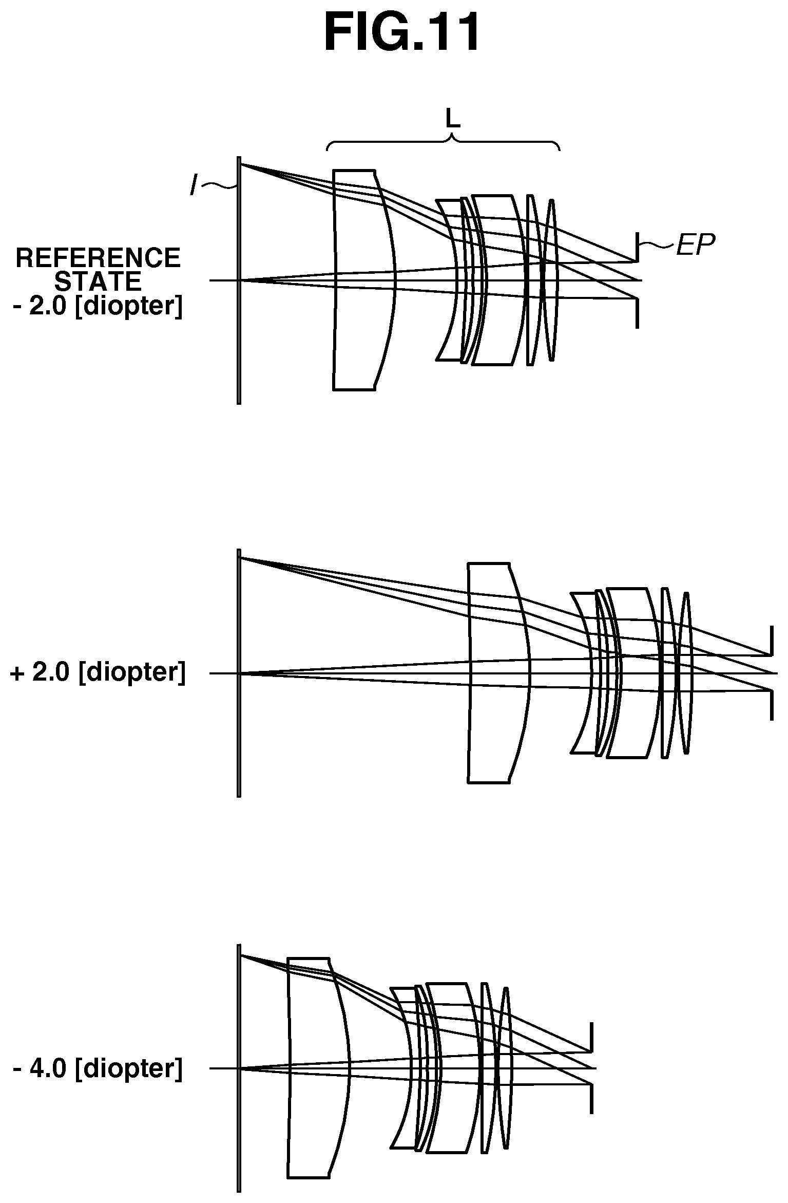
FIG. 11 is a lens cross-sectional view of an eyepiece lens according to a sixth exemplary embodiment.
FIG. 12 illustrates aberration diagrams of the eyepiece lens according to the sixth exemplary embodiment.
FIG. 13 is a lens cross-sectional view of an eyepiece lens according to a seventh exemplary embodiment.
FIG. 14 illustrates aberration diagrams of the eyepiece lens according to the seventh exemplary embodiment.
FIG. 15 is a lens cross-sectional view of an eyepiece lens according to an eighth exemplary embodiment.
FIG. 16 illustrates aberration diagrams of the eyepiece lens according to the eighth exemplary embodiment.
FIG. 17 is a lens cross-sectional view of an eyepiece lens according to a ninth exemplary embodiment.
FIG. 18 illustrates aberration diagrams of the eyepiece lens according to the ninth exemplary embodiment.
FIG. 19 is a lens cross-sectional view of an eyepiece lens according to a tenth exemplary embodiment.
FIG. 20 illustrates aberration diagrams of the eyepiece lens according to the tenth exemplary embodiment.
FIG. 21 is a lens cross-sectional view of an eyepiece lens according to an eleventh exemplary embodiment.
FIG. 22 illustrates aberration diagrams of the eyepiece lens according to the eleventh exemplary embodiment.
FIG. 23 is a lens cross-sectional view of an eyepiece lens according to a twelfth exemplary embodiment.
FIG. 24 illustrates aberration diagrams of the eyepiece lens according to the twelfth exemplary embodiment.
FIG. 25 is a schematic view of a main part of an imaging apparatus according to an exemplary embodiment.
FIGS. 26A and 26B are diagrams each illustrating a relationship between a refractive power arrangement and an optical path of an optical system.
FIGS. 27A and 27B are diagrams each illustrating a relationship between a principal point position and an optical path.
FIG. 28 is a conceptual diagram of a sagittal amount.
DESCRIPTION OF THE EMBODIMENTS
At least one eyepiece lens according to exemplary embodiments of the present disclosure, and an observation apparatus and an imaging apparatus including at least one embodiment of an eyepiece lens will be described in detail below with reference to the accompanying drawings.
FIG. 1 is a lens cross-sectional view of an eyepiece lens according to a first exemplary embodiment, when the diopter of the eyepiece lens is -2.0 (reference state), 2.5, and -6.0. FIG. 2 illustrates aberration diagrams of the eyepiece lens in the reference state according to the first exemplary embodiment. FIG. 3 is a lens cross-sectional view of an eyepiece lens according to a second exemplary embodiment, when the diopter of the eyepiece lens is -2.0 (reference state), 0.7, and -3.3. FIG. 4 illustrates aberration diagrams of the eyepiece lens in the reference state according to the second exemplary embodiment.
FIG. 5 is a lens cross-sectional view of an eyepiece lens according to a third exemplary embodiment, when the diopter of the eyepiece lens is -2.0 (reference state), 2.0, and -4.0. FIG. 6 illustrates aberration diagrams of the eyepiece lens in the reference state according to the third exemplary embodiment. FIG. 7 is a lens cross-sectional view of an eyepiece lens according to a fourth exemplary embodiment, when the diopter of the eyepiece lens is -2.0 (reference state), 2.0, and -4.0. FIG. 8 illustrates aberration diagrams of the eyepiece lens in the reference state according to the fourth exemplary embodiment.
FIG. 9 is a lens cross-sectional view of an eyepiece lens according to a fifth exemplary embodiment, when the diopter of the eyepiece lens is -2.0 (reference state), 2.0, and -4.0. FIG. 10 illustrates aberration diagrams of the eyepiece lens in the reference state according to the fifth exemplary embodiment. FIG. 11 is a lens cross-sectional view of an eyepiece lens according to a sixth exemplary embodiment, when the diopter of the eyepiece lens is -2.0 (reference state), 2.0, and -4.0. FIG. 12 illustrates aberration diagrams of the eyepiece lens in the reference state according to the sixth exemplary embodiment.
FIG. 13 is a lens cross-sectional view of an eyepiece lens according to a seventh exemplary embodiment, when the diopter of the eyepiece lens is -2.0 (reference state), 2.0, and -4.0. FIG. 14 illustrates aberration diagrams of the eyepiece lens in the reference state according to the seventh exemplary embodiment. FIG. 15 is a lens cross-sectional view of an eyepiece lens according to an eighth exemplary embodiment, when the diopter of the eyepiece lens is -2.0 (reference state), 2.4, and -5.8. FIG. 16 illustrates aberration diagrams of the eyepiece lens in the reference state according to the eighth exemplary embodiment.
FIG. 17 is a lens cross-sectional view of an eyepiece lens according to a ninth exemplary embodiment, when the diopter of the eyepiece lens is -2.0 (reference state), 2.0, and -4.0. FIG. 18 illustrates aberration diagrams of the eyepiece lens in the reference state according to the ninth exemplary embodiment. FIG. 19 is a lens cross-sectional view of an eyepiece lens according to a tenth exemplary embodiment, when the diopter of the eyepiece lens is -2.0 (reference state), 2.5, and -6.0. FIG. 20 illustrates aberration diagrams of the eyepiece lens in the reference state according to the tenth exemplary embodiment.
FIG. 21 is a lens cross-sectional view of an eyepiece lens according to an eleventh exemplary embodiment, when the diopter of the eyepiece lens is -2.0 (reference state), 2.5, and -6.0. FIG. 22 illustrates aberration diagrams of the eyepiece lens in the reference state according to the eleventh exemplary embodiment. FIG. 23 is a lens cross-sectional view of an eyepiece lens according to a twelfth exemplary embodiment, when the diopter of the eyepiece lens is -2.0 (reference state), 2.5, and -6.0. FIG. 24 illustrates aberration diagrams of the eyepiece lens in the reference state according to the twelfth exemplary embodiment.
FIG. 25 is a schematic diagram of a main part of an imaging apparatus including the eyepiece lens according to an exemplary embodiment of the present disclosure. FIGS. 26A and 26B are diagrams illustrating that an optical path is changed depending on a refractive power arrangement of an optical system. FIGS. 27A and 27B are diagrams illustrating that an optical path is changed depending on a change in a principal point position of the optical system. FIG. 28 is a conceptual diagram illustrating a sagittal amount.
An eyepiece lens in each exemplary embodiment is used for an electronic viewfinder in an imaging apparatus, such as a digital camera or a video camera. In each lens cross-sectional view, a left side is specified as an image display surface side, and a right side is specified as an observation side. Each lens cross-sectional view includes an eyepiece lens L. An image display surface I of an image display device is configured of a liquid crystal element or an organic electroluminescence (EL) element. An eye point EP is for a user to observe an image displayed on the display surface.
A plate for protecting an image display surface or a lens may be provided between the image display surface I and a lens surface of a first lens at the image display surface side. Further, a plate for protecting a lens may be provided between the eyepiece lens L and the eye point EP. The eye point EP may be moved in an optical axis direction within a range in which an off-axis ray emitted from the image display surface I can pass through pupils of an observer.
Each aberration diagram illustrates an aberration generated in the eyepiece lens in each exemplary embodiment when the finder diopter is in the reference state.
Each spherical aberration diagram illustrates spheric aberration for a d line (wavelength: 587.6 nm) and a g line (wavelength: 435.8 nm). In each astigmatism diagram, astigmatism S is astigmatism on a sagittal image plane, and astigmatism M is astigmatism on a meridional image plane. In each distortion diagram, distortion for a d line is illustrated. In each lateral chromatic aberration diagram, lateral chromatic aberration for a g line is illustrated.
Next, a relationship between the refractive power arrangement of the eyepiece lens and a path of a ray passing through the eyepiece lens will be described with reference to FIGS. 26A, 26B, 27A, and 27B.
A path of a ray in an optical system in which a positive lens is arranged at the most image display surface side of an eyepiece lens and a path of a ray in an optical system in which a negative lens is arranged at the most image display surface side of an eyepiece lens will be compared with reference to FIGS. 26A and 26B. FIG. 26A illustrates a path of a ray in an optical system in which a positive lens is arranged at the most image display surface side of an eyepiece lens. FIG. 26B illustrates a path of a ray in an optical system in which a negative lens is arranged at the most image display surface side of an eyepiece lens.
As illustrated in FIGS. 26A and 26B, the effective diameter of the lens arranged at the most image display surface side (hereinafter referred to as an image display surface side lens) in the eyepiece lens depends on the size of the image display surface. In addition, the effective diameter of the lens arranged at the most observation side (hereinafter referred to as an observation side lens) in the eyepiece lens is determined based on an eye point EP, an angle of view .omega., and an eye relief length ER. As described above, the effective diameters of the image display surface side lens and the observation side lens are determined according to a specification of a finder.
When an eyepiece lens is used for an electronic view finder, it is desirable that an angle of light (image exit angle) exiting from the image display surface and incident on the image display surface side lens is set as small as possible. This is because light obliquely exiting from the image display surface, such as a liquid crystal display surface, is likely to have reduced luminance.
On the other hand, the effective diameter of a lens arranged between the image display surface side lens and the observation side lens (hereinafter referred to as an intermediate lens) is changed according to a refractive power arrangement of the optical system. When a positive lens is used for the image display surface side lens and the observation side lens as illustrated in FIG. 26A, a ray exiting from the image display surface becomes a convergent ray on the image display surface side lens, whereby the effective diameter of the intermediate lens becomes smaller than the effective diameters of the image display surface side lens and the observation side lens. On the other hand, when a negative lens is used for the image display surface side lens and the observation side lens as illustrated in FIG. 26B, a ray exiting from the image display surface becomes a divergent ray, whereby the effective diameter of the intermediate lens becomes larger than the effective diameters of the image display surface side lens and the observation side lens.
As described above, it is desirable to constitute an optical system in such a manner that an image display surface side lens and an observation side lens have positive refractive power to decrease an effective diameter of an intermediate lens.
Next, the situation in which a height of an off-axis ray on a principal point position at the observation side is changed due to a change in a principal point position at the observation side in an optical system will be described with reference to FIGS. 27A and 27B. FIGS. 27A and 27B each schematically illustrate an optical system including a first lens with a positive refractive power, a second lens with a negative refractive power, and a third lens with a positive refractive power in order from the image display surface side to the observation side. FIG. 27A illustrates an optical path when a parallel light is incident in the optical system in which the refractive power of the third lens is set higher than the refractive power of the first lens. FIG. 27B illustrates an optical path when a parallel light is incident in the optical system in which the refractive power of the third lens is set lower than the refractive power of the first lens. FIGS. 27A and 27B are the same in an eye relief and an angle of view.
The comparison between FIGS. 27A and 27B reveals that the principal point position at the observation side in the optical system is shifted to the image display surface side by setting the refractive power of the third lens to be lower than the refractive power of the first lens, so that the height of the ray at the principal point position at the observation side increases.
As described above, with the increase in the refractive power of the positive lens arranged at the observation side, the principal point position at the observation side in the optical system can be shifted to the observation side. Thus, the height of a ray at the principal point position at the observation side can be decreased, resulting in that the effective diameter of the lens arranged near the principal point position at the observation side can be decreased.
The eyepiece lens according to each of the first to fourth exemplary embodiments comprises a first lens with a positive refractive power, a second lens with a negative refractive power, a third lens with a positive refractive power, a fourth lens with a negative refractive power, and a fifth lens with a positive refractive power in order from an object side (image display surface side) to an observation side (eye point side).
In the eyepiece lens according to each of the first to fourth exemplary embodiments, three positive lenses are arranged in such a manner that the refractive power of each lens sequentially becomes higher from the image display surface side to the observation side. With this configuration, the principal point position at the observation side in the eyepiece lens can be shifted to the observation side, whereby the effective diameter of the lens arranged near the principal point position at the observation side can be decreased. In addition, use of three positive lenses can gently refract an off-axis ray, thereby being capable of suppressing a generation of coma and high-order aberration.
The eyepiece lens according to each of the first to fourth exemplary embodiments includes three positive lenses and two negative lenses. With this configuration, a high definition observation image with axial chromatic aberration and lateral chromatic aberration being satisfactorily corrected can be obtained.
In the eyepiece lens L according to each of the first to fourth exemplary embodiments, the diopter can be adjusted by moving all the lenses, i.e., the first lens to the fifth lens, integrally in the optical axis direction. Variations of coma due to a change of the diopter can be suppressed by moving each lens integrally.
It is more desirable that, in the eyepiece lens according to each of the first to fourth exemplary embodiments, one or more of the following conditional expressions are satisfied.
Assume that the focal length of the first lens is defined as f1, the focal length of the third lens is defined as f3, the focal length of the fifth lens is defined as f5, and the focal length of the entire zoom lens of the eyepiece lens is defined as f. Further, assume that the Abbe number of the material of the second lens with respect to the d line is defined as .nu.d2, and the Abbe number of the material of the fourth lens with respect to the d line is defined as .nu.d4. In this case, one or more of the following conditional expressions are desirably satisfied: 1.00<f1/f3<3.15 (1) 1.00<f3/f5<3.33 (2) 0.53<f5/f<0.95 (3) 5.0<.nu.d2<29.2 (4) 5.0<.nu.d4<29.2 (5)
The Abbe number .nu.d is a numerical value represented by .nu.d=(Nd-1)/(NF-NC) where the refractive indices of the material with respect to the F line (486.1 nm), the C line (656.3 nm), and the d line (587.6 nm) are defined respectively as NF, NC, and Nd.
The conditional expression (1) defines a ratio between the focal length f1 of the first lens and the focal length f3 of the third lens. If the ratio exceeds the upper limit value in the conditional expression (1), the positive refractive power of the third lens becomes too high, which results in generating more coma and high-order aberration in the third lens. Thus, it is undesirable.
If the ratio becomes smaller than the lower limit value in the conditional expression (1), the refractive power of the first lens becomes higher than the refractive power of the third lens, so that the principal point position at the observation side of the eyepiece lens is shifted to the image display surface side. This increases the effective diameter of the lens arranged near the principal point position at the observation side. Thus, it is undesirable.
The conditional expression (2) defines a ratio between the focal length f3 of the third lens and the focal length f5 of the fifth lens. If the ratio exceeds the upper limit value in the conditional expression (2), the positive refractive power of the fifth lens becomes too high, which results in generating more coma and high-order aberration in the fifth lens. Thus, it is undesirable.
If the ratio becomes smaller than the lower limit value in the conditional expression (2), the refractive power of the third lens becomes higher than the refractive power of the fifth lens, so that the principal point position at the observation side of the eyepiece lens is shifted to the image display surface side. This increases the effective diameter of the lens arranged near the principal point position at the observation side. Thus, it is undesirable.
The conditional expression (3) defines a ratio between the focal length f5 of the fifth lens and the focal length f of the entire zoom lens of the eyepiece lens. If the ratio exceeds the upper limit value in the conditional expression (3), the positive refractive power of the fifth lens becomes too low, so that the principal point position at the observation side of the eyepiece lens is shifted to the image display surface side. This increases the effective diameter of the lens arranged near the principal point position at the observation side. Thus, it is undesirable.
If the ratio becomes smaller than the lower limit value in the conditional expression (3), the positive refractive power of the fifth lens becomes too high, which results in generating more coma and high-order aberration in the fifth lens. Thus, it is undesirable.
The conditional expression (4) defines the Abbe number .nu.d2 of the material of the second lens with respect to the d line. In the eyepiece lens having a positive refractive power as a whole, negative lenses made of a highly dispersive material are arranged to satisfactorily correct chromatic aberration.
If the Abbe number .nu.d2 becomes smaller than the lower limit value in the conditional expression (4), the chromatic aberration is undesirably corrected too much. In addition, a resin material that can be selected as a lens material is limited. Thus, it is undesirable. If the Abbe number .nu.d2 exceeds the upper limit value in the conditional expression (4), chromatic aberration is difficult to be sufficiently corrected in the eyepiece lens. Thus, it is undesirable.
The conditional expression (5) defines the Abbe number .nu.d4 of the material of the fourth lens with respect to the d line. In the eyepiece lens having a positive refractive power as a whole, negative lenses made of a highly dispersive material are arranged to satisfactorily correct chromatic aberration.
If the Abbe number .nu.d4 becomes smaller than the lower limit value in the conditional expression (5), the chromatic aberration is undesirably corrected too much. In addition, a resin material that can be selected as a lens material is limited. Thus, it is undesirable. If the Abbe number .nu.d4 exceeds the upper limit value in the conditional expression (5), chromatic aberration is difficult to be sufficiently corrected in the eyepiece lens. Thus, it is undesirable.
In the eyepiece lens according to each of the first to fourth exemplary embodiments, the numerical ranges in the conditional expressions (1) to (5) are desirably set as below. 1.02<f1/f3<3.01 (1a) 1.02<f3/f5<3.18 (2a) 0.61<f5/f<0.90 (3a) 10.0<.nu.d2<27.8 (4a) 10.0<.nu.d4<27.8 (5a)
More desirably, the numerical ranges in the conditional expressions (1) to (5) are set as below. 1.05<f1/f3<2.95 (1b) 1.10<f3/f5<3.10 (2b) 0.63<f5/f<0.88 (3b) 15.0<.nu.d2<27.0 (4b) 15.0<.nu.d4<27.0 (5b)
When the eyepiece lens L according to each exemplary embodiment is used for an observation apparatus for observing image information displayed onto the image display surface I, the following conditional expression is desirably satisfied: 0.52<H/f<0.91 (6) where H is the diagonal length of the image display surface I.
The conditional expression (6) defines a ratio between the diagonal length H of the image display surface I and the focal length f of the eyepiece lens.
When the ratio becomes smaller than the lower limit value in the conditional expression (6), and the focal length f of the eyepiece lens becomes too long, the angle of view becomes too narrow. Thus, it is undesirable.
When the ratio exceeds the upper limit value in the conditional expression (6), and the focal length f of the eyepiece lens becomes too short, the effective diameter of the lens arranged at the observation side becomes too large. Consequently, off-axis aberration such as coma or astigmatism is greatly generated. Thus, it is undesirable.
In the first to fourth exemplary embodiments, desirably, the numerical range in the conditional expression (6) is set as below. 0.56<H/f<0.87 (6a)
More desirably, the numerical range in the conditional expression (6) is set as described below. 0.60<H/f<0.85 (6b)
The eyepiece lens according to each of the first to eighth exemplary embodiments comprises a first lens with a positive refractive power, a second lens with a negative refractive power, a third lens with a positive refractive power, and a fourth lens with a negative refractive power in order from an object side (image display surface side) to an observation side (eye point side).
When an eyepiece lens with a long eye relief and wide angle of view is implemented, an observation image might be unclear. The present disclosure provides at least one embodiment of an eyepiece lens comprising at least two positive lenses and at least two negative lenses. With this configuration, a high definition observation image with axial chromatic aberration and lateral chromatic aberration being satisfactorily corrected can be obtained.
In the eyepiece lens L according to each of the first to eighth exemplary embodiments, the diopter can be adjusted by moving all the lenses integrally in the optical axis direction. Variations of coma due to a change of the diopter can be suppressed by moving all lenses integrally.
In the eyepiece lens according to each of the first to eighth exemplary embodiments, the following conditional expression is satisfied: -12.00<(R21+R32)/(R21-R32)<-3.00 (7) where the paraxial curvature radius on the object-side lens surface of the second lens is defined as R21, and the paraxial curvature radius on the observation-side lens surface of the third lens is defined as R32.
When the ratio exceeds the upper limit value in the conditional expression (7), either one of the paraxial curvature radius R21 on the object-side lens surface of the second lens and the paraxial curvature radius R32 of the observation-side lens surface of the third lens becomes too small, which results in difficulty in satisfactorily correcting astigmatic difference. Thus, it is undesirable.
When the ratio becomes smaller than the lower limit value in the conditional expression (7), the difference between the paraxial curvature radius R21 on the object-side lens surface of the second lens and the paraxial curvature radius R32 of the observation-side lens surface of the third lens becomes too small, which results in difficulty in satisfactorily correcting coma. Thus, it is undesirable.
In the eyepiece lens according to each of the first to eighth exemplary embodiments, the numerical range in the conditional expression (7) is desirably set as below. -10.50<(R21+R32)/(R21-R32)<-3.10 (7a)
More desirably, the numerical range in the conditional expression (7) is set as below. -9.00<(R21+R32)/(R21-R32)<-3.20 (7b)
It is further desirable that, in the eyepiece lens according to each of the first to eighth exemplary embodiments, one or more of the following conditional expressions are satisfied: -0.95<f2/f3<-0.32 (8) 5.0<.nu.d2<33.1 (9) 5.0<.nu.d4<28.0 (10)
The focal length of the second lens is defined as f2, the focal length of the third lens is defined as f3, the Abbe number of the material of the second lens with respect to the d line is defined as .nu.d2, and the Abbe number of the material of the fourth lens with respect to the d line is defined as .nu.d4.
The Abbe number .nu.d is a numerical value represented by .nu.d=(Nd-1)/(NF-NC) where the refractive indices of the material with respect to the F line (486.1 nm), the C line (656.3 nm), and the d line (587.6 nm) are defined respectively as NF, NC, and Nd.
The conditional expression (8) defines a ratio between the focal length f2 of the second lens and the focal length f3 of the third lens. If the ratio exceeds the upper limit value in the conditional expression (8), and the focal length f2 of the second lens becomes too short, the refractive power of the second lens becomes too high. Consequently, it becomes difficult to correct spherical aberration. Thus, it is undesirable.
If the ratio becomes smaller than the lower limit value in the conditional expression (8), and the focal length f3 of the third lens becomes too short, the refractive power of the third lens becomes too high. Consequently, it becomes difficult to satisfactorily correct astigmatic difference. Thus, it is undesirable.
The conditional expression (9) defines the Abbe number .nu.d2 of the material of the second lens having a negative refractive power with respect to the d line. In the eyepiece lens having a positive refractive power as a whole, negative lenses made of a highly dispersive material are arranged to satisfactorily correct chromatic aberration.
If the Abbe number .nu.d2 exceeds the upper limit value in the conditional expression (9), it becomes difficult to sufficiently correct the chromatic aberration in the eyepiece lens. Thus, it is undesirable. If the Abbe number .nu.d2 becomes smaller than the lower limit value in the conditional expression (9), the chromatic aberration is undesirably corrected too much. In addition, a resin material that can be selected as a lens material is limited. Thus, it is undesirable.
The conditional expression (10) defines the Abbe number .nu.d4 of the material of the fourth lens having a negative refractive power with respect to the d line. In the eyepiece lens having a positive refractive power as a whole, negative lenses made of a highly dispersive material are arranged to satisfactorily correct chromatic aberration.
If the Abbe number .nu.d4 exceeds the upper limit value in the conditional expression (10), it becomes difficult to sufficiently correct the chromatic aberration in the eyepiece lens. Thus, it is undesirable. If the Abbe number .nu.d4 becomes smaller than the lower limit value in the conditional expression (10), the chromatic aberration is undesirably corrected too much. In addition, a resin material that can be selected as a lens material is limited. Thus, it is undesirable.
In the eyepiece lens according to each of the first to eighth exemplary embodiments, the numerical ranges in the conditional expressions (8) to (10) are desirably set as below. -0.93<f2/f3<-0.34 (8a) 10.0<.nu.d2<31.5 (9a) 10.0<.nu.d4<25.0 (10a)
More desirably, the numerical ranges in the conditional expressions (8) to (10) are set as below. -0.90<f2/f3<-0.36 (8b) 15.0<.nu.d2<30.3 (9b) 15.0<.nu.d4<24.0 (10b)
When the eyepiece lens L according to each of the first to eighth exemplary embodiments is used for an observation apparatus for observing image information displayed on the image display surface I, the following conditional expression is desirably satisfied: 0.52<H/f<0.91 (11) where the focal length of the entire zoom lens of the eyepiece lens is defined as f, and the diagonal length of the image display surface I is defined as H.
The conditional expression (11) defines a ratio between the diagonal length H of the image display surface I and the focal length f of the eyepiece lens.
When the ratio becomes smaller than the lower limit value in the conditional expression (11), and the focal length f of the eyepiece lens becomes too long, the angle of view becomes too narrow. Thus, it is undesirable.
When the ratio exceeds the upper limit value in the conditional expression (11), and the focal length f of the eyepiece lens becomes too short, the effective diameter of the lens arranged at the observation side becomes too large. Consequently, off-axis aberration such as coma or astigmatism is greatly generated. Thus, it is undesirable.
In the first to eighth exemplary embodiments, desirably, the numerical range in the conditional expression (11) is set as below. 0.56<H/f<0.87 (11a)
More desirably, the numerical range in the conditional expression (11) is set as below. 0.60<H/f<0.85 (11b)
The eyepiece lens according to each of the first to fourth and ninth to eleventh exemplary embodiments comprises positive lenses arranged at the most object side (image display surface side) and at the most observation side (eye point side), and one or more negative lenses. If an eyepiece lens is constituted only by a positive lens, a sufficient correction of axial chromatic aberration and lateral chromatic aberration becomes difficult. In view of this, one or more negative lenses are arranged in the eyepiece lens.
As a configuration in which a negative lens is arranged with the number of positive lenses being increased, it is considered that an eyepiece lens is configured by three lenses, i.e., two positive lenses and one negative lens. However, to implement an eyepiece lens having a long eye relief, a wide angle of view, and excellent optical performance, the number of lenses constituting the eyepiece lens has to be increased. In view of this, the eyepiece lens according to at least one embodiment of the present disclosure is configured by using five or more lenses. Preferably, the eyepiece lens includes two or more negative lenses, thereby being capable of satisfactorily correcting axial chromatic aberration and lateral chromatic aberration.
In the eyepiece lens according to each of the first to fourth and ninth to eleventh exemplary embodiments, the following conditional expression is satisfied: 0.58<fe/f<0.95 (12) where the focal length of the lens arranged at the most observation side out of the lenses constituting the eyepiece lens is defined as fe, and the focal length of the entire zoom lens of the eyepiece lens is defined as f.
The conditional expression (12) defines a ratio between the focal length f of the entire zoom lens of the eyepiece lens and the focal length fe of the lens arranged at the most observation side out of the lenses constituting the eyepiece lens.
If the ratio exceeds the upper limit value in the conditional expression (12), and the focal length fe of the lens arranged at the most observation side out of the lenses constituting the eyepiece lens becomes long, the refractive power of the lens arranged at the most observation side becomes too low. Consequently, the principal point position at the observation side in the optical system is shifted to the image display surface side, so that the effective diameter of the lens arranged near the principal point position at the observation side increases. Thus, it is undesirable.
If the ratio becomes smaller than the lower limit value in the conditional expression (12), and the focal length fe of the lens arranged at the most observation side out of the lenses constituting the eyepiece lens becomes short, the refractive power of the lens arranged at the most observation side becomes too high. This results in generating more coma and high-order aberration in the lens arranged at the most object side. Thus, it is undesirable.
In the eyepiece lens according to each of the first to fourth and ninth to eleventh exemplary embodiments, desirably, the numerical range in the conditional expression (12) is set as below. 0.59<fe/f<0.92 (12a)
More desirably, the numerical range in the conditional expression (12) is set as below. 0.61<fe/f<0.90 (12b)
It is further desirable that, in the eyepiece lens according to each of the first to fourth and ninth to eleventh exemplary embodiments, one or more of the following conditional expressions are satisfied: 1.17<ff/fe<4.71 (13) 5.0<.nu.dn<29.2 (14) -3.30<Rf2/Re1<-0.48 (15)
The focal length of the lens arranged at the most object side out of the lenses constituting the eyepiece lens is defined as ff, and the Abbe number of the material of the negative lens constituting the eyepiece lens with respect to the d line is defined as .nu.dn. The paraxial curvature radius on the observation-side lens surface of the lens arranged at the most object side out of the lenses constituting the eyepiece lens is defined as Rf2. The paraxial curvature radius on the object-side lens surface of the lens arranged at the most observation side out of the lenses constituting the eyepiece lens is defined as Re1.
In the conditional expression (14), the Abbe number .nu.dn is a numerical value represented by .nu.dn=(Nd-1)/(NF-NC) where the refractive indices of the material with respect to the F line (486.1 nm), the C line (656.3 nm), and the d line (587.6 nm) are defined respectively as NF, NC, and Nd.
The conditional expression (13) defines a ratio between the focal length fe of the lens arranged at the most observation side and the focal length ff of the lens arranged at the most object side. If the ratio exceeds the upper limit value in the conditional expression (13), and the focal length fe of the lens arranged at the most observation side becomes too short, the refractive power of the lens arranged at the most observation side becomes too high. Consequently, it becomes difficult to sufficiently correct spherical aberration. Thus, it is undesirable.
If the ratio becomes smaller than the lower limit value in the conditional expression (13), and the focal length ff of the lens arranged at the most object side becomes too short, the refractive power of the lens arranged at the most object side becomes too high. Consequently, it becomes difficult to sufficiently correct astigmatic difference. Thus, it is undesirable.
The conditional expression (14) defines the Abbe number .nu.dn of the material of the negative lens constituting the eyepiece lens with respect to the d line. In the eyepiece lens having a positive refractive power as a whole, negative lenses made of a highly dispersive material are arranged to satisfactorily correct chromatic aberration.
If the Abbe number .nu.dn exceeds the upper limit value in the conditional expression (14), it becomes difficult to sufficiently correct the chromatic aberration in the eyepiece lens. Thus, it is undesirable. If the Abbe number .nu.dn becomes smaller than the lower limit value in the conditional expression (14), the chromatic aberration is undesirably corrected too much. In addition, a resin material that can be selected as a lens material is limited. Thus, it is undesirable.
The conditional expression (15) defines a ratio between the curvature radius Rf2 on the observation-side lens surface of the lens arranged at the most object side and the curvature radius Re1 on the object-side lens surface of the lens arranged at the most observation side. If the ratio exceeds the upper limit value in the conditional expression (15), and the absolute value of the curvature radius Rf2 becomes small, the refractive power of the observation-side lens surface of the lens arranged at the most object side becomes too high. Therefore, it becomes difficult to reduce astigmatism difference and spherical aberration. Thus, it is undesirable.
If the ratio becomes smaller than the lower limit value in the conditional expression (15), and the absolute value of the curvature radius Re1 becomes small, the refractive power of the object-side lens surface of the lens arranged at the most observation side becomes too high. Therefore, it becomes difficult to reduce variations of coma due to a change of the diopter. Thus, it is undesirable.
Desirably, in the eyepiece lens according to each of the first to fourth and ninth to eleventh exemplary embodiments, the numerical ranges in the conditional expressions (13) to (15) are set as described below. 1.20<ff/fe<4.50 (13a) 10.0<.nu.dn<28.0 (14a) -3.15<Rf2/Re1<-0.50 (15a)
More desirably, the numerical ranges in the conditional expressions (13) to (15) are set as below. 1.25<ff/fe<4.30 (13b) 15.0<.nu.dn<26.8 (14b) -3.10<Rf2/Re1<-0.52 (15b)
When the eyepiece lens L according to each exemplary embodiment is used for an observation apparatus for observing image information displayed on the image display surface I, the following conditional expression is desirably satisfied: 0.52<H/f<0.91 (16) where the diagonal length of the image display surface I is defined as H.
The conditional expression (16) defines a ratio between the diagonal length H of the image display surface I and the focal length f of the eyepiece lens.
When the ratio becomes smaller than the lower limit value in the conditional expression (16), and the focal length f of the eyepiece lens becomes too long, the angle of view becomes too narrow. Thus, it is undesirable.
When the ratio exceeds the upper limit value in the conditional expression (16), and the focal length f of the eyepiece lens becomes too short, off-axis aberration such as coma or astigmatism is greatly generated. Thus, it is undesirable.
In the first to fourth and ninth to eleventh exemplary embodiments, desirably, the numerical range in the conditional expression (16) is set as below. 0.56<H/f<0.87 (16a)
More desirably, the numerical range in the conditional expression (16) is set as below. 0.60<H/f<0.85 (16b)
In the eyepiece lens L according to each of the first to fourth and ninth to eleventh exemplary embodiments, the diopter can be adjusted by moving all the lenses integrally in the optical axis direction. Variations of coma due to a change of the diopter can be suppressed by moving all lenses integrally.
The eyepiece lens according to each of the first, fourth to seventh, ninth, tenth, and twelfth exemplary embodiments includes three or more lenses, each having a lens surface with an aspheric shape rotationally symmetrical about an optical axis (hereinafter referred to as aspheric lenses), and includes five or more lenses as a whole eyepiece lens.
To implement an eyepiece lens having a long distance (eye relief) from the lens surface at the most observation side of the eyepiece lens to an eye point, and a wide angle of view, the lens diameter of the eyepiece lens is generally increased, whereby an off-axis ray passes through the position far apart from the optical axis. This entails a problem such that off-axis aberration such as coma, curvature of field, or distortion is greatly generated.
In the eyepiece lens according to each of the first, fourth to seventh, ninth, tenth, and twelfth exemplary embodiments, three or more aspheric lenses are used to satisfactorily correct off-axis aberration such as coma, curvature of field, and distortion.
When an eyepiece lens with a long eye relief and wide angle of view is implemented, an observation image might be unclear. The eyepiece lens according to each of the first, fourth to seventh, ninth, tenth, and twelfth exemplary embodiments includes two or more positive lenses, and two or more negative lenses. With this configuration, a high definition observation image with an axial chromatic aberration and a lateral chromatic aberration being satisfactorily corrected can be obtained.
In the eyepiece lens L according to each of the first, fourth to seventh, ninth, tenth, and twelfth exemplary embodiments, the diopter can be adjusted by moving all the lenses integrally in the optical axis direction. Variations of coma due to a change of the diopter can be suppressed by moving all lenses integrally.
In addition, in the eyepiece lens L according to each of the first, fourth to seventh, ninth, tenth, and twelfth exemplary embodiments, one or more of the following conditional expressions are desirably satisfied: 0.007<|Sagmax/RS|<0.200 (17) 0.003<|Sagmax/fS|<0.150 (18) 0.23<ER/f<1.05 (19) 5.0<.nu.dn<34.0 (20)
In these conditional expressions, the difference between the sagittal amount of the surface with a paraxial curvature radius and the sagittal amount of the lens surface with an aspheric shape at the maximum height where an off-axis ray passes on or through the lens surface with an aspheric shape is defined as Sag. The paraxial curvature radius of the lens surface with an aspheric shape by which the absolute value |Sag| of the difference between the sagittal amounts becomes maximum is defined as RS. The maximum value of the absolute value |Sag| of the difference between the sagittal amounts is defined as Sagmax.
The difference Sag between the sagittal amounts will be described with reference to FIG. 28. The sagittal amount indicates a distance between a vertical line from a vertex of the lens surface to the optical axis and the lens surface based on the maximum height (the distance from the optical axis) where the off-axis ray passes through the lens surface having an aspheric shape rotationally symmetrical about the optical axis. When the sagittal amount of the surface with a paraxial curvature radius is defined as .DELTA.(S), and the sagittal amount of the lens surface having an aspheric shape is defined as .DELTA.(As), the difference Sag between the sagittal amounts is represented as Sag=.DELTA.(S)-.DELTA.(As)
The focal length of the lens with the lens surface having an aspheric shape by which the absolute value |Sag| of the difference between the sagittal amounts becomes the maximum is defined as fS, the distance (eye relief) from the lens surface at the most observation side of the eyepiece lens to the eye point is defined as ER, and the focal length of the entire zoom lens of the eyepiece lens is defined as f. In addition, the Abbe number of the material of the negative lens constituting the eyepiece lens with respect to the d line is defined as .nu.dn.
The Abbe number .nu.dn is a numerical value represented by .nu.dn=(Nd-1)/(NF-NC) where the refractive indices of the material with respect to the F line (486.1 nm), the C line (656.3 nm), and the d line (587.6 nm) are defined respectively as NF, NC, and Nd.
If the ratio exceeds the upper limit value in the conditional expression (17), and the maximum value Sagmax of the absolute value |Sag| of the difference between the sagittal amounts with respect to the paraxial curvature radius RS becomes large, off-axis aberration is corrected too much. Thus, it is undesirable. Further, the formation of the lens surface with an aspheric shape becomes difficult. Thus, it is undesirable.
If the ratio becomes smaller than the lower limit value in the conditional expression (17), and the maximum value Sagmax of the absolute value |Sag| of the difference between the sagittal amounts with respect to the paraxial curvature radius RS becomes small, off-axis aberration is difficult to be sufficiently corrected. Thus, it is undesirable.
An eyepiece lens having a long eye relief, a wide angle of view, and high optical performance can be obtained by appropriately setting the shape of the aspheric lens in order that the conditional expression (17) is satisfied.
If the ratio exceeds the upper limit value in the conditional expression (18), the maximum value Sagmax of the absolute value |Sag| of the difference between the sagittal amounts with respect to the focal length fS of the lens with a lens surface of an aspheric shape by which the absolute value |Sag| of the difference between the sagittal amounts becomes maximum becomes too large. As a result, off-axis aberration is corrected too much. Thus, it is undesirable. In addition, the refractive power of the lens with a lens surface of an aspheric shape by which the absolute value |Sag| of the difference between the sagittal amounts becomes maximum becomes too high. Therefore, more spherical aberration and coma occurs. Thus, it is undesirable.
If the ratio becomes smaller than the lower limit value in the conditional expression (18), the maximum value Sagmax of the absolute value |Sag| of the difference between the sagittal amounts with respect to the focal length fS of the lens with a lens surface of an aspheric shape by which the absolute value |Sag| of the difference between the sagittal amounts becomes maximum becomes too small. As a result, off-axis aberration is difficult to be sufficiently corrected. Thus, it is undesirable.
The conditional expression (19) defines a ratio between the focal length f of the entire zoom lens of the eyepiece lens and the eye relief ER. When the ratio exceeds an upper limit value in the conditional expression (19), and the eye relief ER becomes long, the effective diameter of the lens arranged at the most observation side increases, so that the off-axis aberration is difficult to be sufficiently corrected. Thus, it is undesirable.
If the ratio becomes smaller than the lower limit value in the conditional expression (19), and the eye relief ER becomes short, the angle of view becomes too narrow. Thus, it is undesirable.
The conditional expression (20) defines the Abbe number .nu.dn of the material of the negative lens constituting the eyepiece lens with respect to the d line. In the eyepiece lens having a positive refractive power as a whole, negative lenses made of a highly dispersive material are arranged to satisfactorily correct chromatic aberration.
If the Abbe number .nu.dn exceeds the upper limit value in the conditional expression (20), it becomes difficult to sufficiently correct the chromatic aberration in the eyepiece lens. Thus, it is undesirable. If the Abbe number .nu.dn becomes smaller than the lower limit value in the conditional expression (20), the chromatic aberration is undesirably corrected too much. In addition, a resin material that can be selected as a lens material is limited. Thus, it is undesirable.
Desirably, in the eyepiece lens according to each of the first, fourth to seventh, ninth, tenth, and twelfth exemplary embodiments, the numerical ranges in the conditional expressions (17) to (20) are set as below. 0.015<|Sagmax/RS|<0.120 (17a) 0.010<|Sagmax/fS|<0.075 (18a) 0.24<ER/f<1.00 (19a) 10.0<.nu.dn<30.2 (20a)
More desirably, the numerical ranges in the conditional expressions (17) to (20) are set as below. 0.024<|Sagmax/RS|<0.075 (17b) 0.018<|Sagmax/fS|<0.040 (18b) 0.25<ER/f<0.98 (19b) 15.0<.nu.dn<24.0 (20b)
When the eyepiece lens L according to each exemplary embodiment is used for an observation apparatus for observing image information displayed on the image display surface I, the following conditional expression is desirably satisfied: 0.52<H/f<0.91 (21) where the diagonal length of the image display surface I is defined as H.
The conditional expression (21) defines a ratio between the diagonal length H of the image display surface I and the focal length f of the eyepiece lens.
When the ratio becomes smaller than the lower limit value in the conditional expression (21), and the focal length f of the eyepiece lens becomes too long, the angle of view becomes too narrow. Thus, it is undesirable.
When the ratio exceeds the upper limit value in the conditional expression (21), and the focal length f of the eyepiece lens becomes too short, the effective diameter of the lens arranged at the observation side becomes too large. As a result, off-axis aberration such as coma or astigmatism is greatly generated on the lens arranged at the observation side. Thus, it is undesirable.
Desirably, in each of the first, fourth to seventh, ninth, tenth, and twelfth exemplary embodiments, the numerical range in the conditional expression (21) is set as below. 0.56<H/f<0.87 (21a)
More desirably, the numerical range in the conditional expression (21) is set as below. 0.60<H/f<0.85 (21b)
Next, first to twelfth numerical embodiments respectively corresponding to the first to twelfth exemplary embodiments of the present disclosure will be described. In each numerical embodiment, i represents an order of an optical surface from the image display surface side. ri represents the paraxial curvature radius of the i-th optical surface (i-th surface), and di represents the interval between the i-th surface and the (i+1)-th surface. Further, ndi and .nu.di each represent the refractive index and the Abbe number of the material of the ith optical member with respect to the d line. r1 represents the image display surface, and r2 represents the surface of the plate protecting the image display surface. The surface at the most observation side indicates the eye point EP.
The aspheric shape is represented by x=(h.sup.2/R)/[1+[1-(1+K)(h/R).sup.2].sup.1/2]+A4h.sup.4+A6h.sup.6+A8h.su- p.8 where K is eccentricity, A4, A6, and A8 are aspheric coefficients, and a displacement in the optical axis direction at the position of the height h from the optical axis is defined as x with the surface vertex being defined as a reference. In addition, R is a paraxial curvature radius. The surface with * at the right of a surface number means that this surface is aspheric. "e-Z" indicates "10.sup.-Z".
Numerical Embodiment 1 (EX. 1)
TABLE-US-00001 Unit mm Surface Data Surface Number r d nd .nu.d 1 .infin. 0.70 1.51000 60.0 2 .infin. (Variable) 3 -65.737 3.95 2.00069 25.5 4 -22.170 3.52 5* -14.334 3.00 1.63550 23.8 6* 110.330 0.30 7* 48.492 6.84 1.53110 55.9 8* -21.874 1.20 9* 128.789 1.41 1.63550 23.8 10* 22.276 1.20 11 39.057 8.21 1.83481 42.7 12 -39.057 27.00 13 (Eye Point) Aspheric Surface Data 5th Surface K = -7.28787e-001 A4 = -6.03675e-005 A6 = 1.77471e-007 6th Surface K = 4.51650e+001 A4 = -1.11796e-005 A6 = -6.19143e-008 7th Surface K = -4.38548e+000 A4 = -2.38798e-005 A6 = -2.65742e-008 8th Surface K = -1.22703e+000 A4 = -4.69821e-006 A6 = 3.91413e-008 9th Surface K = -2.69921e+002 A4 = -1.52881e-007 A6 = -4.63945e-009 10th Surface K = -4.63925e+000 A4 = 4.39848e-006 A6 = 5.19693e-010 Various Data Diopter [diopter] -2.0 +2.5 -6.0 Focal Length 28.56 28.56 28.56 d2 9.12 12.79 5.80
Numerical Embodiment 2 (EX. 2)
TABLE-US-00002 Unit mm Surface Data Surface Number r d nd .nu.d 1 .infin. 0.70 1.51000 60.0 2 .infin. (Variable) 3 -65.913 3.14 2.00069 25.5 4 -48.248 10.11 5 -34.250 3.19 1.76182 26.5 6 -1000.301 1.69 7* -4010.368 6.95 1.58313 59.4 8* -44.146 1.21 9* 161.388 5.20 1.63550 23.8 10* 44.387 1.20 11 64.814 8.88 1.83481 42.7 12 -64.313 27.00 13 (Eye Point) Aspheric Surface Data 7th Surface K = 1.33592e+004 A4 = -7.84416e-006 A6 = 7.50739e-009 8th Surface K = -6.98689e-001 A4 = 3.30466e-006 A6 = -8.53288e-009 9th Surface K = -2.65944e+002 A4 = -3.33664e-006 A6 = -9.10796e-009 10th Surface K = -9.09514e+000 A4 = -5.30646e-006 A6 = 3.91499e-009 Various data Diopter [diopter] -2.0 +0.7 -3.3 Focal Length 61.32 61.32 61.32 d2 21.46 31.12 17.55
Numerical Embodiment 3 (EX. 3)
TABLE-US-00003 Unit mm Surface Data Surface Number r d nd .nu.d 1 .infin. 0.70 1.51000 60.0 2 .infin. (Variable) 3 -158.559 2.41 2.00069 25.5 4 -77.911 20.00 5 -30.833 8.00 1.95906 17.5 6 -72.834 3.39 7 188.533 7.00 1.83481 42.7 8 -56.340 1.20 9 40.450 1.71 1.84666 23.8 10 23.822 1.20 11 25.956 4.79 1.91082 35.3 12 64.549 27.00 13 (Eye Point) Various Data Diopter [diopter] -2.0 +2.0 -4.0 Focal Length 52.34 52.34 52.34 d2 11.05 21.99 6.18
Numerical Embodiment 4 (EX. 4)
TABLE-US-00004 Unit mm Surface Data Surface Number r d nd .nu.d 1 .infin. 0.70 1.51000 60.0 2 .infin. (Variable) 3* -98.827 11.19 1.85135 40.1 4* -71.371 20.00 5* -49.765 3.00 1.63550 23.8 6* -407.575 1.11 7* -1171.461 7.94 1.49171 57.4 8* -82.367 1.20 9* 219.883 3.76 1.63550 23.8 10* 74.863 1.23 11* 95.021 8.12 1.80610 40.7 12* -92.616 27.00 13 (Eye Point) Aspheric Surface Data 3rd Surface K = 4.54099e-001 A4 = 3.40725e-008 A6 = 7.53032e-011 A8 = -1.51639e-013 4th Surface K = 3.40970e-001 A4 = 8.48720e-008 A6 = -4.76459e-011 A8 = 1.79616e-014 5th Surface K = 3.53841e-001 6th Surface K = -1.00057e+003 7th Surface K = -2.99780e+003 A4 = -5.75156e-006 A6 = 7.03535e-009 8th Surface K = -1.18365e+000 A4 = 4.34382e-006 A6 = -5.53385e-009 9th Surface K = 1.75400e+001 A4 = -2.52412e-006 A6 = -7.75632e-009 10th Surface K = -1.05760e+001 A4 = -6.88282e-006 A6 = 3.02568e-009 11th Surface K = 3.83428e+000 12th Surface K = 1.63448e+000 Various Data Diopter [diopter] -2.0 +2.0 -4.0 Focal Length 91.98 91.98 91.98 d2 31.59 66.08 20.00
Numerical Embodiment 5 (EX. 5)
TABLE-US-00005 Unit mm Surface Data Surface Number r d nd .nu.d 1 .infin. 0.70 1.51000 60.0 2 .infin. (Variable) 3* 166.099 9.26 1.53110 55.9 4* -34.164 6.60 5* -28.931 3.82 1.63550 23.8 6* -93.400 0.47 7* -153.697 3.79 1.53110 55.9 8* -50.254 2.12 9* -40.174 6.83 1.63550 23.8 10* -56.296 1.20 11 -3131.870 4.55 1.53110 55.9 12 -62.412 1.20 13 110.718 3.36 1.49700 81.5 14 -332.326 27.00 15 (Eye Point) Aspheric Surface Data 3rd Surface K = -9.59406e+001 A4 = -2.43307e-006 A6 = -5.82983e-009 4th Surface K = 3.24062e-001 A4 = 2.14830e-006 A6 = 2.81943e-009 5th Surface K = 9.32664e-002 A4 = -5.63898e-007 A6 = 2.57659e-008 6th Surface K = -8.05489e+000 A4 = 6.49218e-007 A6 = -1.63252e-010 7th Surface K = -4.96939e+001 A4 = -1.17845e-006 A6 = -4.58865e-009 8th Surface K = 2.90402e-001 A4 = -2.46377e-006 A6 = 5.28440e-009 9th Surface K = -1.87452e-001 A4 = 1.66992e-006 A6 = -7.39182e-009 10th Surface K = 2.96336e+000 A4 = 4.16642e-007 A6 = 1.08928e-009 Various Data Diopter [diopter] -2.0 +2.0 -4.0 Focal Length 52.34 52.34 52.34 d2 22.29 33.23 17.21
Numerical Embodiment 6 (EX. 6)
TABLE-US-00006 Unit mm Surface Data Surface Number r d nd .nu.d 1 .infin. 0.70 1.51000 60.0 2 .infin. (Variable) 3 -1201.003 20.00 1.48749 70.2 4 -89.718 20.00 5* -64.550 3.06 1.63550 23.8 6* -160.023 2.00 7* -230.109 3.54 1.53110 55.9 8* -119.762 1.20 9* -86.800 12.72 1.63550 23.8 10* -103.753 1.20 11 5354.752 4.23 1.60311 60.6 12 -123.568 1.20 13 178.678 3.96 1.49700 81.5 14 -351.151 27.00 15 (Eye Point) Aspheric Surface Data 5th Surface K = 2.64919e+000 A4 = -7.42759e-007 6th Surface K = -6.77987e+001 A4 = -2.49183e-008 7th Surface K = 6.98083e+001 A4 = -1.18509e-006 8th Surface K = 5.02189e+000 A4 = -2.98254e-006 A6 = -1.01200e-009 9th Surface K = 2.92913e+000 A4 = 1.34769e-006 10th Surface K = 1.50370e+000 A4 = -8.31493e-007 Various Data Diopter [diopter] -2.0 +2.0 -4.0 Focal Length 104.68 104.68 104.68 d2 32.12 76.83 17.13
Numerical Embodiment 7 (EX. 7)
TABLE-US-00007 Unit mm Surface Data Surface Number R d nd .nu.d 1 .infin. 0.70 1.51000 60.0 2 .infin. (Variable) 3* 136.125 8.69 1.69350 53.2 4* -43.222 8.67 5* -28.738 3.00 1.63550 23.8 6* -89.027 0.30 7* -231.429 5.74 1.53110 55.9 8* -46.578 2.68 9* -39.537 2.66 1.63550 23.8 10* -55.894 1.84 11* -2299.162 5.94 1.53110 55.9 12* -60.213 1.20 13 110.718 4.00 1.55332 71.7 14 -332.326 27.00 15 (Eye Point) Aspheric Surface Data 3rd Surface K = -6.07439e+000 A4 = -1.82896e-006 A6 = -5.07089e-009 4th Surface K = 5.99930e-001 A4 = 1.41427e-006 A6 = 4.25770e-010 5th Surface K = 1.13826e-001 A4 = -6.11987e-007 A6 = 2.58066e-008 6th Surface K = -7.86704e+000 A4 = 6.27492e-007 A6 = -5.81898e-010 7th Surface K = -3.07481e+001 A4 = -8.80513e-007 A6 = -3.57889e-009 8th Surface K = 5.53963e-001 A4 = -2.76657e-006 A6 = 4.45282e-009 9th Surface K = -1.40844e-001 A4 = 1.47140e-006 A6 = -7.32877e-009 10th Surface K = 3.06010e+000 A4 = 6.99258e-007 A6 = 1.21727e-009 11th Surface K = 1.00225e+004 A4 = -2.66396e-007 A6 = 8.58565e-011 A8 = 9.72106e-013 12th Surface K = -3.51427e-001 A4 = 2.36708e-007 A6 = 2.33340e-010 A8 = -4.05287e-013 Various Data Diopter [diopter] -2.0 +2.0 -4.0 Focal Length 45.99 45.99 45.99 d2 19.29 27.62 15.12
Numerical Embodiment 8 (EX. 8)
TABLE-US-00008 Unit mm Surface Data Surface Number r d nd .nu.d 1 .infin. 0.70 1.51633 64.1 2 .infin. (Variable) 3 547.471 4.04 1.71300 53.9 4 -23.889 2.74 5 -14.779 1.14 1.69895 30.1 6 39.283 9.03 1.91082 35.3 7 -24.063 (Variable) 8 -16.665 1.09 1.80809 22.8 9 -94.061 4.60 1.83481 42.7 10 -22.997 0.17 11 184.850 2.92 1.88300 40.8 12 -58.904 27.00 13 (Eye Point) Various Data Diopter [diopter] -2.0 +2.4 -5.8 Focal Length 28.97 29.87 27.10 d2 6.58 9.93 4.95 d7 8.39 10.64 3.20
Numerical Embodiment 9 (EX. 9)
TABLE-US-00009 Unit mm Surface Data Surface Number r d nd .nu.d 1 .infin. 0.70 1.51000 60.0 2 .infin. (Variable) 3* 85.611 7.93 1.63278 23.3 4* -73.248 11.44 5* -38.173 2.99 1.63550 23.8 6 .infin. 2.00 7 -50.000 2.00 1.63550 23.8 8* 63.180 1.08 9 80.000 3.73 1.83481 42.7 10 -120.000 3.63 11* 44.916 11.36 1.53110 55.9 12* -38.064 27.00 13 (Eye Point) Aspheric Surface Data 3rd Surface K = -3.90666e+001 A4 = 1.18895e-005 A6 = -1.59624e-008 4th Surface K = 1.15096e+001 A4 = 8.63593e-006 A6 = -4.12233e-009 5th Surface K = -1.92831e+000 A4 = -7.44051e-006 A6 = -6.66949e-008 8th Surface K = 6.40443e+000 A4 = -1.12216e-005 A6 = -5.11268e-008 11th Surface K = 6.47203e-001 A4 = -1.83397e-005 A6 = -3.67313e-008 12th Surface K = -4.15340e+000 A4 = -1.79314e-005 A6 = 8.95990e-009 Various Data Diopter [diopter] -2.0 +2.0 -4.0 Focal Length 52.35 52.35 52.35 d2 12.84 23.84 7.81
Numerical Embodiment 10 (EX. 10)
TABLE-US-00010 Unit mm Surface Data Surface Number r d nd .nu.d 1 .infin. 0.70 1.51000 60.0 2 .infin. (Variable) 3* -38.535 14.01 1.63278 23.3 4* -29.517 1.20 5* 24.703 7.75 1.53110 55.9 6* -192.936 1.07 7* -230.075 4.76 1.63550 23.8 8* 18.027 8.01 9* 37.444 3.24 1.63550 23.8 10* 30.304 3.65 11* 53.230 10.15 1.53110 55.9 12* -35.174 27.00 13 (Eye Point) Aspheric Surface Data 3rd Surface K = -2.22441e+000 4th Surface K = -1.18255e+000 5th Surface K = -1.32449e+000 A4 = 7.79653e-006 A6 = -2.68440e-008 6th Surface K = 2.37035e+001 A4 = 5.59136e-006 A6 = 2.14521e-008 7th Surface K = 1.36735e+002 A4 = 8.57582e-006 A6 = 1.39697e-008 8th Surface K = -1.09087e+000 A4 = 4.16185e-005 A6 = -1.08061e-007 9th Surface K = -1.50678e+001 A4 = 8.86960e-006 A6 = 1.79036e-008 10th Surface K = -1.08863e+001 A4 = -3.03939e-006 A6 = 3.51421e-008 11th Surface K = -1.20352e+000 12th Surface K = 3.09095e-001 Various Data Diopter [diopter] -2.0 +2.5 -6.0 Focal Length 52.34 52.34 52.34 d2 15.82 28.22 5.80
Numerical Embodiment 11 (EX. 11)
TABLE-US-00011 Unit mm Surface Data Surface Number r d nd .nu.d 1 .infin. 0.70 1.51000 60.0 2 .infin. (Variable) 3 -52.901 3.89 2.00069 25.5 4 -21.121 3.61 5* -13.287 2.00 1.63550 23.8 6 -295.010 0.20 7 112.818 1.52 1.49171 57.4 8* 109.641 0.30 9* 48.133 6.44 1.53110 55.9 10* -21.455 1.20 11* 395.724 1.20 1.63550 23.8 12* 22.567 1.20 13 39.762 8.07 1.83481 42.7 14 -39.762 27.00 15 (Eye Point) Aspheric Surface Data 5th Surface K = -7.56869e-001 A4 = -5.88991e-005 A6 = 2.21474e-007 8th Surface K = 4.38705e+001 A4 = -1.19423e-005 A6 = -6.22491e-008 9th Surface K = -4.78924e+000 A4 = -2.40504e-005 A6 = -2.98503e-008 10th Surface K = -1.90079e+000 A4 = -1.90004e-007 A6 = 3.37043e-008 11th Surface K = -3.09759e+003 A4 = -8.85806e-007 A6 = -7.73712e-010 12th Surface K = -4.48834e+000 A4 = 3.15962e-006 A6 = 1.14086e-009 Various Data Diopter [diopter] -2.0 +2.5 -6.0 Focal Length 28.56 28.56 28.56 d2 9.12 12.78 5.80
Numerical Embodiment 12 (EX. 12)
TABLE-US-00012 Unit mm Surface Data Surface Number r d nd .nu.d 1 .infin. 0.70 1.51000 60.0 2 .infin. (Variable) 3 -18.559 1.00 1.64769 33.8 4 405.260 8.54 1.69350 53.2 5* -30.810 1.18 6* 161.494 7.67 1.49171 57.4 7 -38.921 0.10 8* 48.932 8.43 1.49171 57.4 9 -97.046 0.10 10 33.326 1.20 1.69895 30.1 11 22.887 30.00 12 (Eye Point) Aspheric Surface Data 5th Surface K = -6.54146e-003 6th Surface K = -2.64204e+002 A4 = -3.16425e-006 A6 = -2.31819e-009 8th Surface K = 1.87604e+000 Various Data Diopter [diopter] -2.0 +2.5 6.0 Focal Length 50.29 50.29 50.29 d2 28.47 40.02 20.00
TABLE-US-00013 TABLE 1 Ex. 1 Ex. 2 Ex. 3 Ex. 4 f1/f3 1.09 2.16 2.86 1.41 f3/f5 1.20 1.92 1.17 3.03 f5/f 0.86 0.65 0.86 0.65 vd2 23.8 26.5 17.5 23.8 vd4 23.8 23.8 23.8 23.8 H/f 0.64 0.83 0.73 0.83
TABLE-US-00014 TABLE 2 Ex. 1 Ex. 2 Ex. 3 Ex. 4 Ex. 5 Ex. 6 Ex. 7 Ex. 8 (R21 + R32)/ -4.80 -7.92 -3.42 -4.05 -3.71 -3.34 -4.22 -4.18 (R21 - R32) f2/f3 -0.67 -0.61 -1.17 -0.50 -0.49 -0.37 -0.63 -0.87 vd2 23.8 26.5 17.5 23.8 23.8 23.8 23.8 30.1 vd4 23.8 23.8 23.8 23.8 23.8 23.8 23.8 22.8 H/f 0.64 0.83 0.73 0.83 0.73 0.73 0.83 0.64
TABLE-US-00015 TABLE 3 Ex. 1 Ex. 2 Ex. 3 Ex. 4 Ex. 9 Ex. 10 Ex. 11 fe/f 0.86 0.65 0.86 0.65 0.78 0.79 0.87 ff/fe 1.30 4.14 3.35 4.28 1.56 3.00 1.33 vdn 23.8 26.5 17.5 23.8 23.8 23.8 23.8 23.8 23.8 23.8 23.8 23.8 23.8 57.4 23.8 Rf2/Re1 -0.57 -0.74 -3.00 -0.75 -1.63 -0.55 -0.53 H/f 0.64 0.83 0.73 0.83 0.63 0.73 0.64
TABLE-US-00016 TABLE 4 Ex. 1 Ex. 4 Ex. 5 Ex. 6 Ex. 7 Ex. 9 Ex. 10 Ex. 12 | Sagmax/RS | 0.072 0.033 0.008 0.016 0.072 0.033 0.187 0.008 | Sagmax/fS | 0.038 0.014 0.024 0.004 0.031 0.036 0.129 0.020 ER/f 0.95 0.29 0.52 0.26 0.59 0.52 0.52 0.60 vdn 23.8 23.8 23.8 23.8 23.8 23.8 23.8 33.8 23.8 23.8 23.8 23.8 23.8 23.8 23.8 30.1 H/f 0.64 0.83 0.73 0.73 0.83 0.63 0.73 0.64
Next, an exemplary embodiment of a video camera including the eyepiece lens illustrated in each exemplary embodiment will be described with reference to FIG. 25.
In FIG. 25, the video camera includes a video camera body 10, a photographic optical system 11 forming an object image on an image sensor (not illustrated), and a sound collection microphone 12. An observation apparatus (electronic viewfinder) 13 is used to observe an object image displayed on an image display device (not illustrated) through the eyepiece lens according to at least one embodiment of the present disclosure. The image display device is constituted by a liquid crystal panel or the like, and displays an object image or the like formed by the photographic optical system 11.
While the present inventions have been described with reference to exemplary embodiments, it is to be understood that the inventions are not limited to the disclosed exemplary embodiments. The scope of the following claims is to be accorded the broadest interpretation so as to encompass all such modifications and equivalent structures and functions.
This application claims the benefit of Japanese Patent Application No. 2014-176291, filed Aug. 29, 2014, Japanese Patent Application No. 2014-176293, filed Aug. 29, 2014, Japanese Patent Application No. 2014-176294, filed Aug. 29, 2014, and Japanese Patent Application No. 2014-176295, filed Aug. 29, 2014, which applications are hereby incorporated by reference herein in their entireties.
* * * * *
D00000
D00001
D00002
D00003
D00004
D00005
D00006
D00007
D00008
D00009
D00010
D00011
D00012

D00013

D00014

D00015

D00016

D00017

D00018
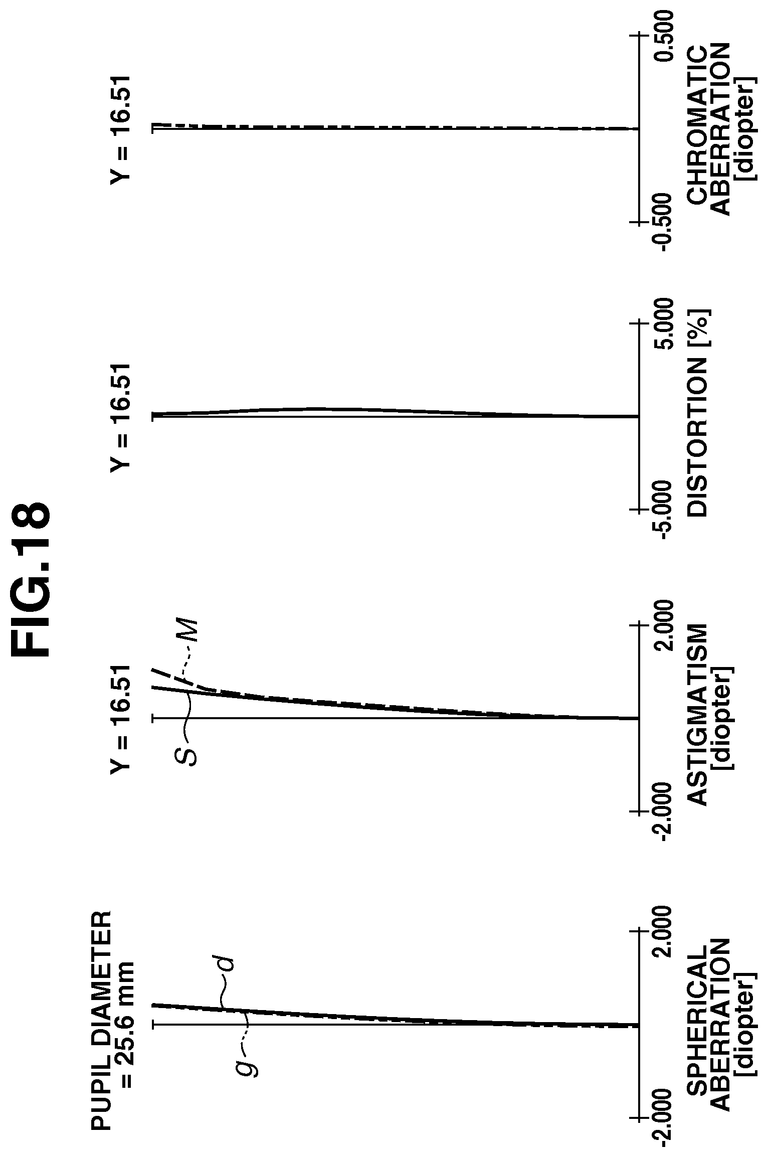
D00019

D00020
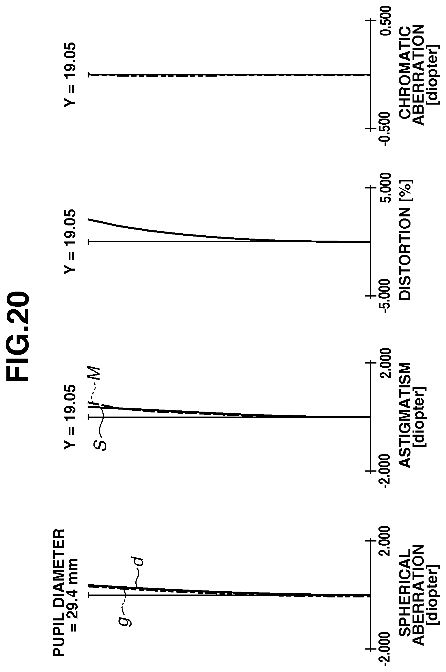
D00021

D00022

D00023

D00024
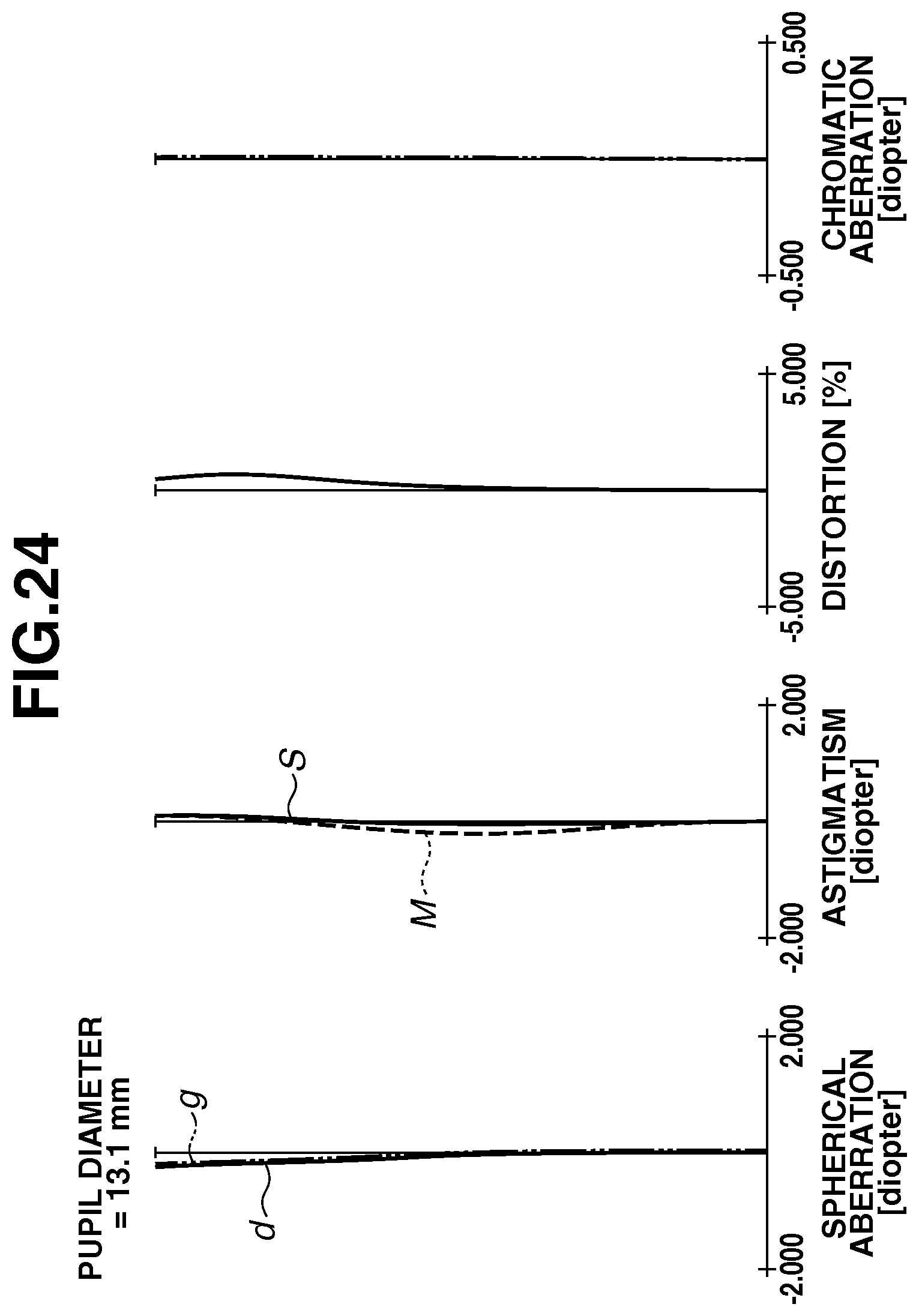
D00025

D00026
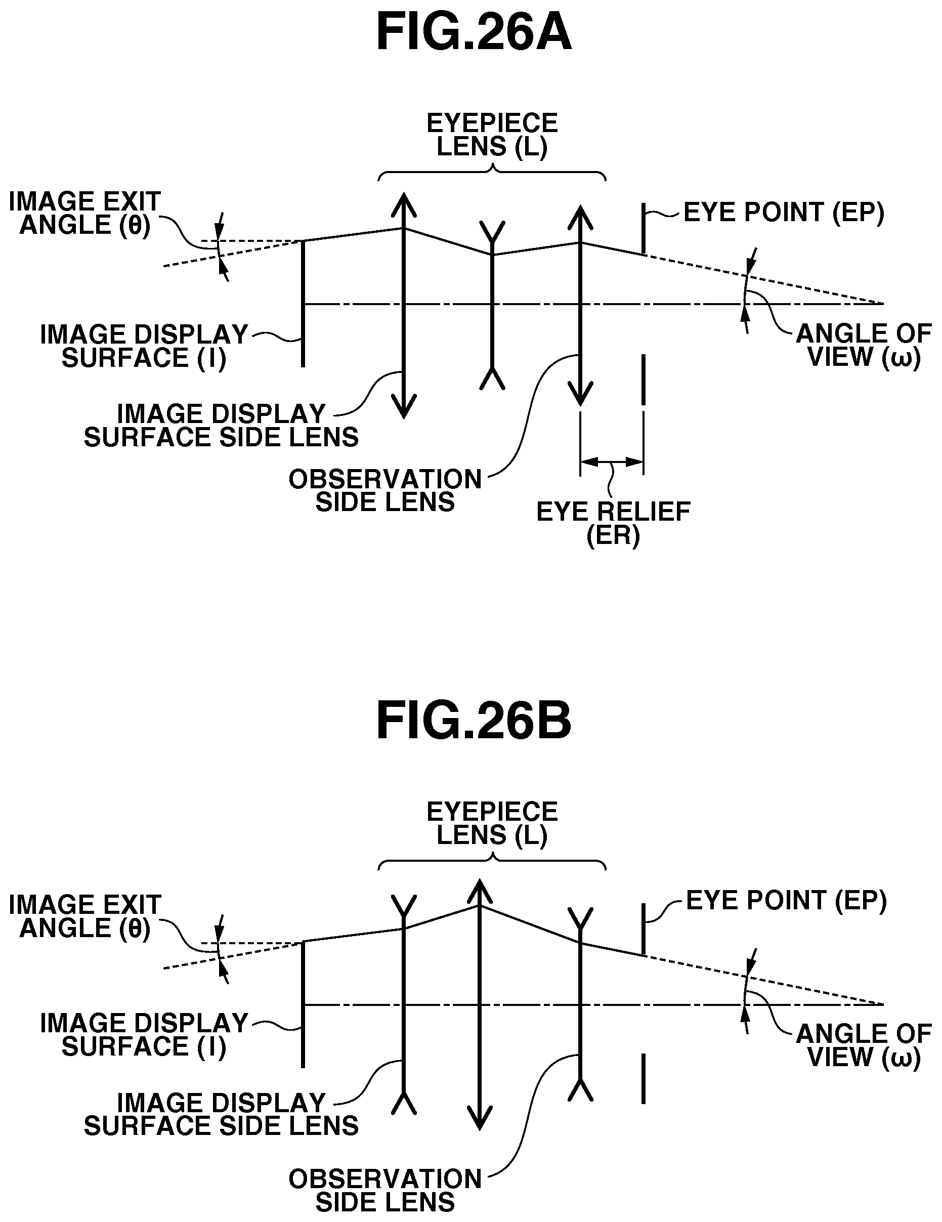
D00027

D00028

XML
uspto.report is an independent third-party trademark research tool that is not affiliated, endorsed, or sponsored by the United States Patent and Trademark Office (USPTO) or any other governmental organization. The information provided by uspto.report is based on publicly available data at the time of writing and is intended for informational purposes only.
While we strive to provide accurate and up-to-date information, we do not guarantee the accuracy, completeness, reliability, or suitability of the information displayed on this site. The use of this site is at your own risk. Any reliance you place on such information is therefore strictly at your own risk.
All official trademark data, including owner information, should be verified by visiting the official USPTO website at www.uspto.gov. This site is not intended to replace professional legal advice and should not be used as a substitute for consulting with a legal professional who is knowledgeable about trademark law.