Camera lens assembly and camera device
Zhang , et al. Sep
U.S. patent number 10,761,289 [Application Number 15/766,288] was granted by the patent office on 2020-09-01 for camera lens assembly and camera device. This patent grant is currently assigned to Zhejiang Sunny Optical Co., Ltd.. The grantee listed for this patent is ZHEJIANG SUNNY OPTICAL CO., LTD. Invention is credited to Ming Li, Jianke Wenren, Kaiyuan Zhang.


View All Diagrams
| United States Patent | 10,761,289 |
| Zhang , et al. | September 1, 2020 |
Camera lens assembly and camera device
Abstract
A camera lens assembly is provided. The camera lens assembly, comprises sequentially, from an object side to an image side along an optical axis, a first lens, multiple subsequent lenses, and a photosensitive element arranged on an image plane, wherein the first lens has a negative focal power and an object side surface of the first lens is a concave surface; and an axial distance from the object side surface of the first lens to the image plane TTL and ImgH, ImgH being half a diagonal length of an effective pixel area of the photosensitive element, satisfy: 1.5<TTL/ImgH<1.7.
| Inventors: | Zhang; Kaiyuan (Ningbo, CN), Wenren; Jianke (Ningbo, CN), Li; Ming (Ningbo, CN) | ||||||||||
|---|---|---|---|---|---|---|---|---|---|---|---|
| Applicant: |
|
||||||||||
| Assignee: | Zhejiang Sunny Optical Co.,
Ltd. (CN) |
||||||||||
| Family ID: | 58354691 | ||||||||||
| Appl. No.: | 15/766,288 | ||||||||||
| Filed: | April 20, 2017 | ||||||||||
| PCT Filed: | April 20, 2017 | ||||||||||
| PCT No.: | PCT/CN2017/081195 | ||||||||||
| 371(c)(1),(2),(4) Date: | April 05, 2018 | ||||||||||
| PCT Pub. No.: | WO2018/103250 | ||||||||||
| PCT Pub. Date: | June 14, 2018 |
Prior Publication Data
| Document Identifier | Publication Date | |
|---|---|---|
| US 20190278044 A1 | Sep 12, 2019 | |
Foreign Application Priority Data
| Dec 5, 2016 [CN] | 2016 1 1100838 | |||
| Current U.S. Class: | 1/1 |
| Current CPC Class: | G02B 7/021 (20130101); G02B 9/62 (20130101); G02B 13/0045 (20130101); H04N 5/2254 (20130101) |
| Current International Class: | G02B 9/62 (20060101); G02B 7/02 (20060101); H04N 5/225 (20060101); G02B 13/00 (20060101) |
References Cited [Referenced By]
U.S. Patent Documents
| 8687292 | April 2014 | Tsai et al. |
| 9696527 | July 2017 | Wang |
| 9829683 | November 2017 | Chae |
| 2014/0009844 | January 2014 | Tsai et al. |
| 2015/0362709 | December 2015 | Wang |
| 2016/0147044 | May 2016 | Kondo |
| 2016/0154210 | June 2016 | Baik et al. |
| 2016/0161717 | June 2016 | Chae |
| 2017/0108666 | April 2017 | Lee |
| 103529538 | Jan 2014 | CN | |||
| 105676417 | Jun 2016 | CN | |||
| 105759406 | Jul 2016 | CN | |||
| 106019535 | Oct 2016 | CN | |||
| 106526801 | Mar 2017 | CN | |||
| 20160095935 | Aug 2016 | KR | |||
Other References
|
Chinese Office Action (translated) for Chinese Patent Application No. 201611100838, dated May 28, 2018, 8 pgs. cited by applicant. |
Primary Examiner: Martinez; Joseph P
Attorney, Agent or Firm: Barnes & Thornburg LP
Claims
What is claimed is:
1. A camera lens assembly, comprising sequentially, from an object side to an image side along an optical axis, a first lens, a second lens, a third lens, a fourth lens, a fifth lens and a sixth lens, and a photosensitive element arranged on an image plane, wherein, the first lens has a negative focal power, and an object side surface of the first lens is a concave surface; an object side surface of the third lens is a concave surface; an object side surface of the fourth lens is a concave surface; and an axial distance from the object side surface of the first lens to the image plane TTL and ImgH, ImgH being half a diagonal length of an effective pixel area of the photosensitive element, satisfy: 1.5<TTL/ImgH<1.7.
2. The camera lens assembly according to claim 1, wherein: the second lens has a positive focal power or a negative focal power, wherein an image side surface of the second lens is a concave surface; the third lens has a positive focal power, wherein an image side surface of the third lens is a convex surface; and the fourth lens has a negative focal power; the fifth lens has a positive focal power, wherein an object side surface of fifth lens is a concave surface, and an image side surface of the fifth lens is a convex surface; and the sixth lens has a positive focal power or a negative focal power.
3. The camera lens assembly according to claim 2, wherein a half of a maximum field-of-view angle HFOV of the camera lens assembly satisfies: HFOV>50.degree..
4. The camera lens assembly according to claim 2, wherein a center thickness of the second lens on the optical axis CT2 and a center thickness of the third lens on the optical axis CT3 satisfy: 1<CT2/CT3<1.5.
5. The camera lens assembly according to claim 2, wherein an effective focal length of the fourth lens f4 and a total effective focal length of the camera lens assembly f satisfy: -2<f4/f<-1.
6. The camera lens assembly according to claim 2, wherein an effective focal length of the third lens f3 and an effective focal length of the fifth lens f5 satisfy: 0.4<f3/f5<1.
7. The camera lens assembly according to claim 2, wherein an axial distance between an intersection point of the object side surface of the fifth lens and the optical axis and a vertex of an effective radius of the object side surface of the fifth lens SAG51 and the axial distance from the object side surface of the first lens to the image plane TTL satisfy: -0.2<SAG51/TTL<-0.1.
8. The camera lens assembly according to claim 2, wherein a radius of curvature of the object side surface of the fifth lens R9 and a radius of curvature of the image side surface of the fifth lens R10 satisfy: 1<R9/R10<1.5.
9. The camera lens assembly according to claim 2, wherein an axial spacing distance between the third lens and the fourth lens T34 and an axial spacing distance between the fifth lens and the sixth lens T56 satisfy: 0.5<T34/T56<1.2.
10. The camera lens assembly according to claim 2, wherein an effective radius of the object side surface of the first lens DT11 and an effective radius of the image side surface of the fifth lens DT52 satisfy: 0.5<DT11/DT52<1.1.
11. A camera lens assembly, comprising sequentially, from an object side to an image side along an optical axis: a first lens, having a negative focal power, and an object side surface of the first lens being a concave surface; a second lens, having a positive focal power or a negative focal power, and an image side surface of the second lens being a concave surface; a third lens, having a positive focal power, and an object side surface of the third lens being a concave surface, and an image side surface of the third lens being a convex surface; a fourth lens, having a negative focal power, and an object side surface of the fourth lens being a concave surface; a fifth lens, having a positive focal power, and an object side surface of the fifth lens being a concave surface, and an image side surface of the fifth lens being a convex surface; and a sixth lens, having a positive focal power or a negative focal power, an axial spacing distance between the third lens and the fourth lens T34 and an axial spacing distance between the fifth lens and the sixth lens T56 satisfying: 0.5<T34/T56<1.2.
12. The camera lens assembly according to claim 11, further comprising: a photosensitive element, arranged on an image plane, wherein an axial distance from the object side surface of the first lens to the image plane TTL and ImgH, ImgH being half a diagonal length of an effective pixel area of the photosensitive element, satisfy: 1.5<TTL/ImgH<1.7.
13. The camera lens assembly according to claim 11, wherein a half of a maximum field-of-view angle HFOV of the camera lens assembly satisfies: HFOV>50.degree..
14. The camera lens assembly according to claim 11, wherein a center thickness of the second lens on the optical axis CT2 and a center thickness of the third lens on the optical axis CT3 satisfy: 1<CT2/CT3<1.5.
15. The camera lens assembly according to claim 11, wherein an effective focal length of the fourth lens f4 and a total effective focal length of the camera lens assembly f satisfy: -2<f4/f<-1.
16. The camera lens assembly according to claim 11, wherein an effective focal length of the third lens f3 and an effective focal length of the fifth lens f5 satisfy: 0.4<f3/f5<1.
17. The camera lens assembly according to claim 11, wherein an axial distance between an intersection point of the object side surface of the fifth lens and the optical axis and a vertex of an effective radius of the object side surface of the fifth lens SAG51 and the axial distance from the object side surface of the first lens to the image plane TTL satisfy: -0.2<SAG51/TTL<-0.1.
18. The camera lens assembly according to claim 11, wherein a radius of curvature of the object side surface of the fifth lens R9 and a radius of curvature of the image side surface of the fifth lens R10 satisfy: 1<R9/R10<1.5.
19. The camera lens assembly according to claim 11, wherein an effective radius of the object side surface of the first lens DT11 and an effective radius of the image side surface of the fifth lens DT52 satisfy: 0.5<DT11/DT52<1.1.
20. A camera device, equipped with a camera lens assembly, the camera lens assembly comprising sequentially, from an object side to an image side along an optical axis, a first lens, a second lens, a third lens, a fourth lens, a fifth lens and a sixth lens, and a photosensitive element arranged on an image plane, wherein, the first lens has a negative focal power, and an object side surface of the first lens is a concave surface; object side surface of the third lens is a concave surface; an object side surface of the fourth lens is a concave surface; an axial distance from the object side surface of the first lens to the image plane TTL and ImgH, ImgH being half a diagonal length of an effective pixel area of the photosensitive element, satisfy: 1.5<TTL/ImgH<1.7.
Description
CROSS-REFERENCE TO RELATED APPLICATIONS
This application is a U.S. national counterpart application of international application serial No. PCT/CN2017/081195 filed Apr. 20, 2017, which claims priority to Chinese Patent Application No. 201611100838.3, filed Dec. 5, 2016. The disclosures of both PCT/CN2017/081195 and Chinese Patent Application No. 201611100838.3 are hereby incorporated by reference.
TECHNICAL FIELD
The present application relates to a camera lens assembly and a camera device equipped with the camera lens assembly.
BACKGROUND
Image information is an important class of information that can be obtained by humans, and an optical lens is almost the only entry point for obtaining the image information. With the progress in science and technology, quality and information quantity of an image obtained by the population are continuously increasing. The quality of the image is mainly achieved by increasing the pixel sampling density of a photosensitive element. Therefore, an increase of an aperture in a system and an increase of transfer function of each field of view of the system are needed to meet the above requirement. The information quantity of the image obtained by the optical system may be represented by an optical invariant of the system, and the optical invariant of the system increases linearly with the field of view of the optical system.
Therefore, in order to increase the information quantity of the obtained image, a main approach is to increase the field of view of the optical system. At present, with the development of mobile phone lenses, consumers have higher and higher demands for selfies. Accordingly, it is quite necessary to develop a wide-angle lens assembly that has a large field of view and high resolution and is suitable for taking the selfie. Due to the height limit of the mobile phone lens, the length of the optical system is compressed as much as possible while taking the large field of view, the high resolution and high yield rate into account.
SUMMARY
The present application provides technical solutions that at least meet the above-mentioned requirements.
According to an aspect, the present application provides a camera lens assembly. The camera lens assembly, from an object side to an image side along an optical axis, includes sequentially: a first lens having a negative focal power, wherein an object side surface of the first lens is a concave surface; a second lens having a focal power, wherein an image side surface of the second lens is a concave surface; a third lens having a positive focal power, wherein an object side surface of the third lens is a concave surface, and an image side surface of the third lens is a convex surface; a fourth lens having a negative focal power, wherein an object side surface of the fourth lens is a concave surface; a fifth lens having a positive focal power, wherein an object side surface of the fifth lens is a concave surface, and an image side surface of the fifth lens is a convex surface; and a sixth lens having a focal power. The camera lens assembly further includes an electronic photosensitive element, arranged on an image plane along the optical axis.
According to an embodiment of the present application, an axial distance from the object side surface of the first lens to the image plane TTL and ImgH, ImgH being half a diagonal length of an effective pixel area of the photosensitive element, may satisfy: 1.5<TTL/ImgH<1.7, for example, 1.583.ltoreq.TTL/ImgH.ltoreq.1.660.
According to another aspect, a camera lens assembly provided by the present application, from an object side to an image side along an optical axis, includes sequentially: a first lens having a negative focal power, wherein an object side surface of the first lens is a concave surface; a second lens, of which an image side surface is a concave surface; a third lens having a positive focal power, wherein an object side surface of the third lens is a concave surface, and an image side surface of the third lens is a convex surface; a fourth lens having a negative focal power, wherein an object side surface of the fourth lens is a concave surface; a fifth lens having a positive focal power, wherein an object side surface of the fifth lens is a concave surface, and an image side surface of the fifth lens is a convex surface; and a sixth lens having a positive focal power or a negative focal power. An axial spacing distance between the third lens and the fourth lens T34 and an axial spacing distance between the fifth lens and the sixth lens T56 satisfy: 0.5<T34/T56<1.2, for example, 0.633.ltoreq.T34/T56.ltoreq.1.118.
According to an embodiment of the present application, for example, a half of a maximum field-of-view angle HFOV of the camera lens assembly may be set to: HFOV>50.degree..
According to an embodiment of the present application, a center thickness of the second lens on the optical axis CT2 and a center thickness of the third lens on the optical axis CT3 may satisfy: 1<CT2/CT3<1.5, for example, 1.028.ltoreq.CT2/CT3.ltoreq.1.424.
According to an embodiment of the present application, an effective focal length of the fourth lens f4 and a total effective focal length of the camera lens assembly f may satisfy: -2<f4/f<-1, for example, -1.573.ltoreq.f4/f.ltoreq.-1.336.
According to an embodiment of the present application, an effective focal length of the third lens f3 and an effective focal length of the fifth lens f5 may satisfy: 0.4<f3/f5<1, for example, 0.458.ltoreq.f3/f5.ltoreq.0.915.
According to an embodiment of the present application, an axial distance between an intersection point of the object side surface of the fifth lens and the optical axis and a vertex of an effective radius of the object side surface of the fifth lens SAG51 and an axial distance from the object side surface of the first lens to the image plane TTL may satisfy: -0.2<SAG51/TTL<-0.1, for example, -0.144.ltoreq.SAG51/TTL.ltoreq.-0.119.
According to an embodiment of the present application, a radius of curvature of the object side surface of the fifth lens R9 and a radius of curvature of the image side surface of the fifth lens R10 may satisfy: 1<R9/R10<1.5, for example, 1.166.ltoreq.R9/R10.ltoreq.1.419.
According to an embodiment of the present application, an axial spacing distance between the third lens and the fourth lens T34 and an axial spacing distance between the fifth lens and the sixth lens T56 may satisfy: 0.5<T34/T56<1.2, for example, 0.633.ltoreq.T34/T56.ltoreq.1.118.
According to an embodiment of the present application, an effective radius of the object side surface of the first lens DT11 and an effective radius of the image side surface of the fifth lens DT52 may satisfy: 0.5<DT11/DT52<1.2, for example, 0.608.ltoreq.DT11/DT52.ltoreq.1.150.
According to another aspect, the present application provides a camera device, equipped with the camera lens assembly described above.
In the present application, multiple lenses (e.g., six lenses) having plastic aspheric surfaces are used. By reasonably distributing focal powers and surface forms of the multiple lenses, the viewing angle of the camera lens assembly can be effectively increased, and thus, miniaturization of the lens assembly can be ensured and image quality can be improved.
BRIEF DESCRIPTION OF THE DRAWINGS
The above and other advantages of the embodiments according to the present application will become apparent through detailed description given with reference to accompanying drawings, and the accompanying drawings are intended to illustrate exemplary embodiments of the present application, rather than a limitation to the exemplary embodiments of the present application. In the accompanying drawings:
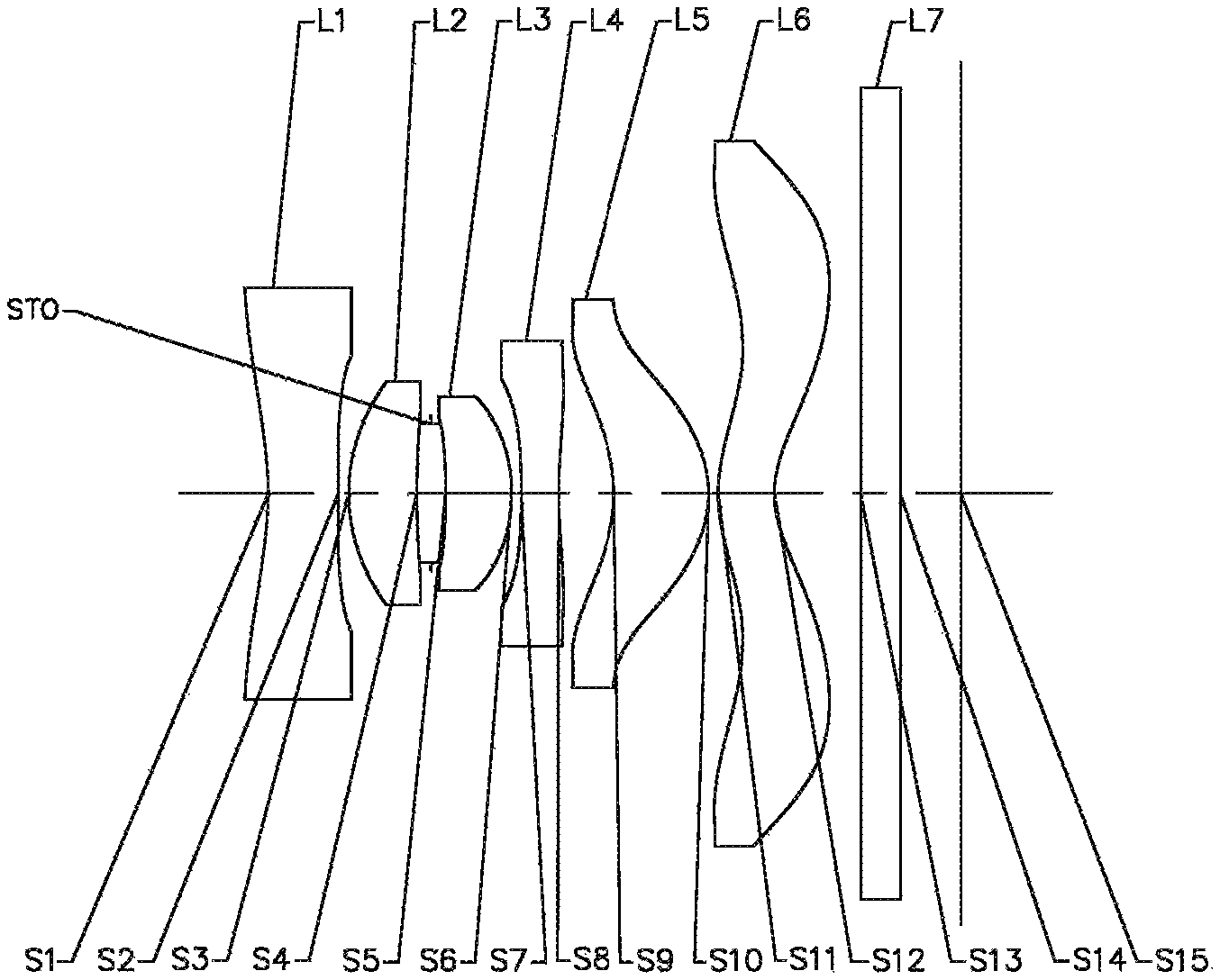
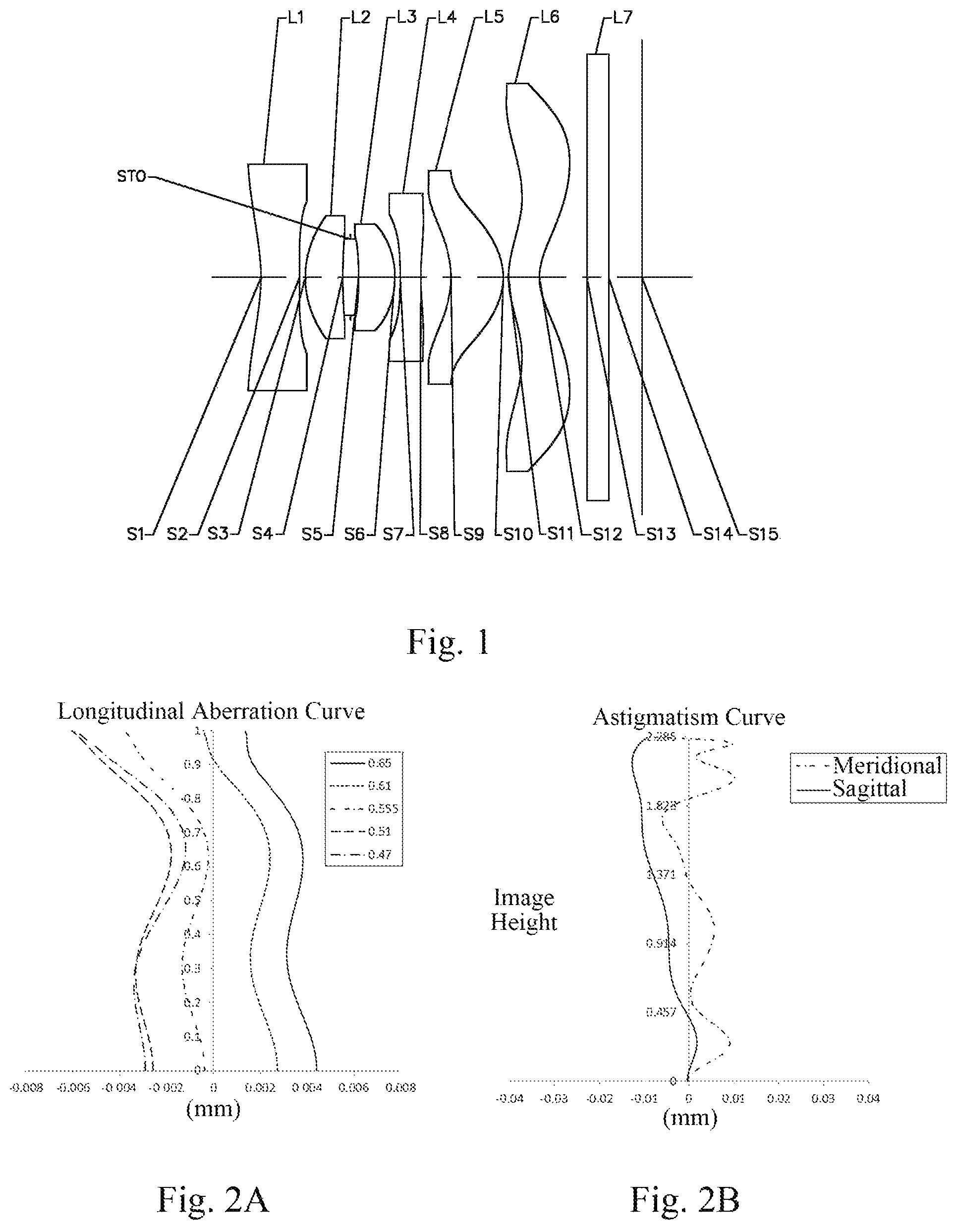
FIG. 1 is a schematic structural diagram of a camera lens assembly according to Embodiment 1 of the present application;
FIG. 2A illustrates a longitudinal aberration curve of the camera lens assembly according to Embodiment 1;
FIG. 2B illustrates an astigmatism curve of the camera lens assembly according to Embodiment 1;
FIG. 2C illustrates a lateral color curve of the camera lens assembly according to Embodiment 1;
FIG. 3 is a schematic structural diagram of a camera lens assembly according to Embodiment 2 of the present application;
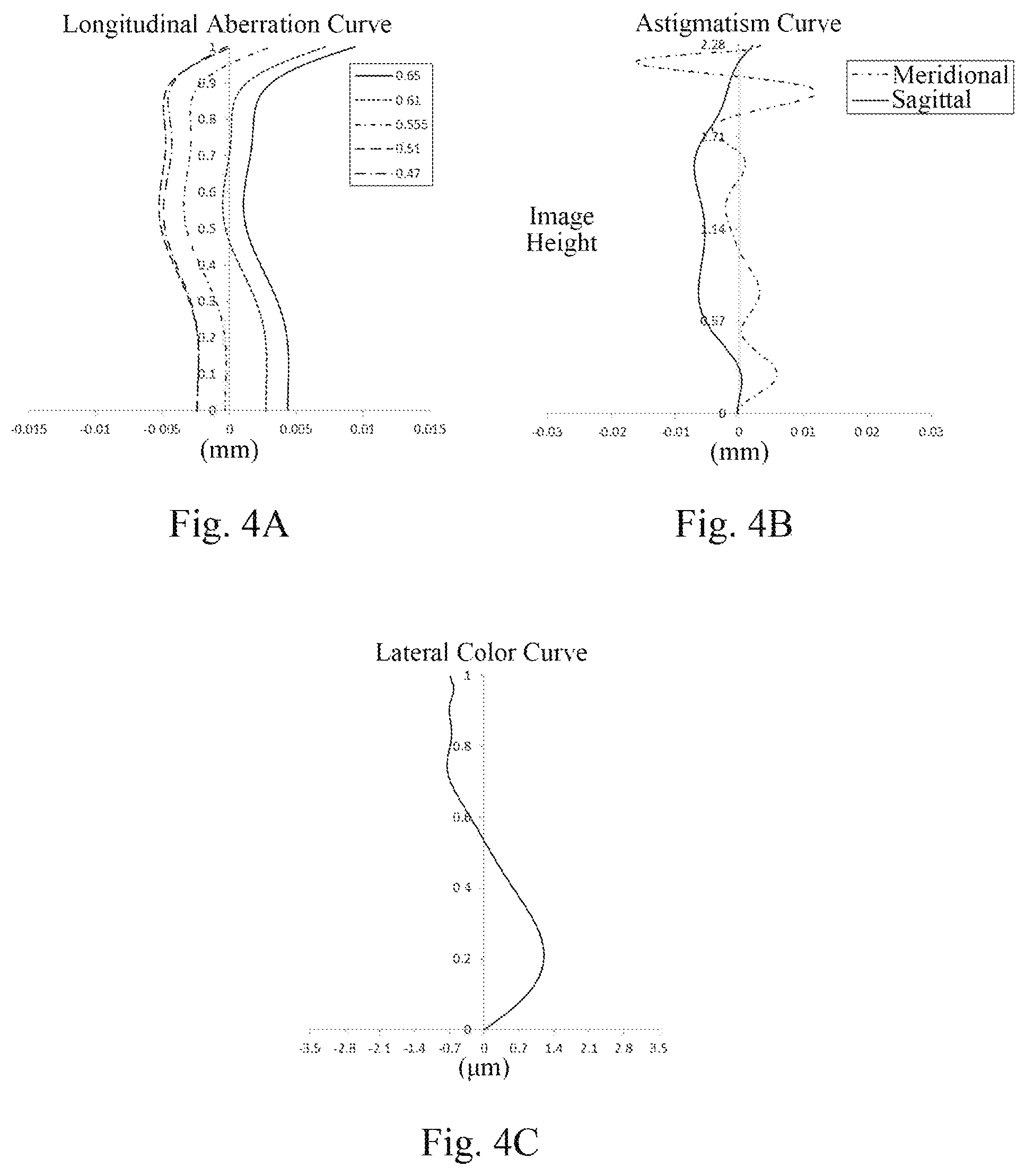
FIG. 4A illustrates a longitudinal aberration curve of the camera lens assembly according to Embodiment 2;
FIG. 4B illustrates an astigmatism curve of the camera lens assembly according to Embodiment 2;
FIG. 4C illustrates a lateral color curve of the camera lens assembly according to Embodiment 2;
FIG. 5 is a schematic structural diagram of a camera lens assembly according to Embodiment 3 of the present application;
FIG. 6A illustrates a longitudinal aberration curve of the camera lens assembly according to Embodiment 3;
FIG. 6B illustrates an astigmatism curve of the camera lens assembly according to Embodiment 3;
FIG. 6C illustrates a lateral color curve of the camera lens assembly according to Embodiment 3;
FIG. 7 is a schematic structural diagram of a camera lens assembly according to Embodiment 4 of the present application;
FIG. 8A illustrates a longitudinal aberration curve of the camera lens assembly according to Embodiment 4;
FIG. 8B illustrates an astigmatism curve of the camera lens assembly according to Embodiment 4;
FIG. 8C illustrates a lateral color curve of the camera lens assembly according to Embodiment 4;
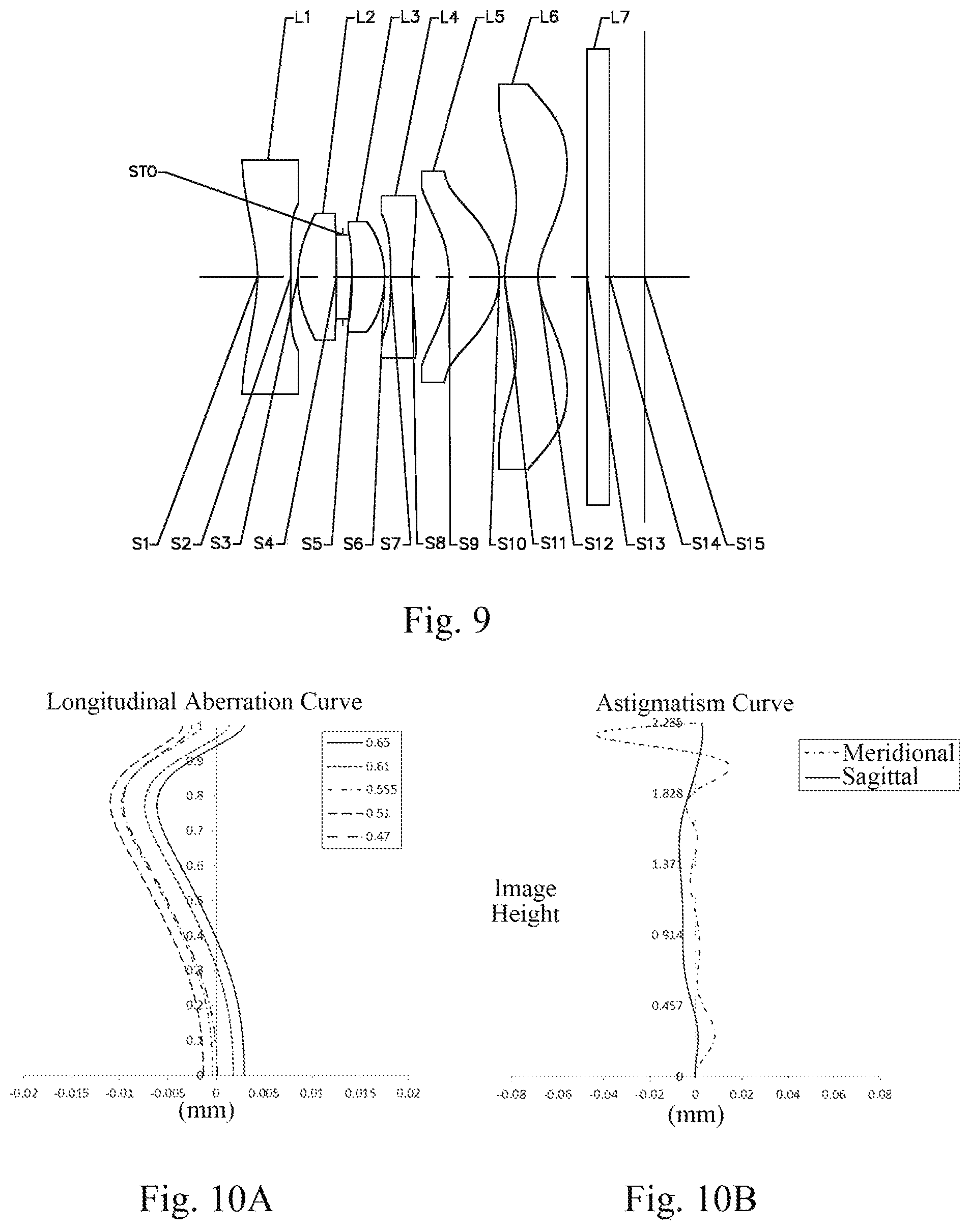
FIG. 9 is a schematic structural diagram of a camera lens assembly according to Embodiment 5 of the present application;
FIG. 10A illustrates a longitudinal aberration curve of the camera lens assembly according to Embodiment 5;
FIG. 10B illustrates an astigmatism curve of the camera lens assembly according to Embodiment 5;
FIG. 10C illustrates a lateral color curve of the camera lens assembly according to Embodiment 5;
FIG. 11 is a schematic structural diagram of a camera lens assembly according to Embodiment 6 of the present application;
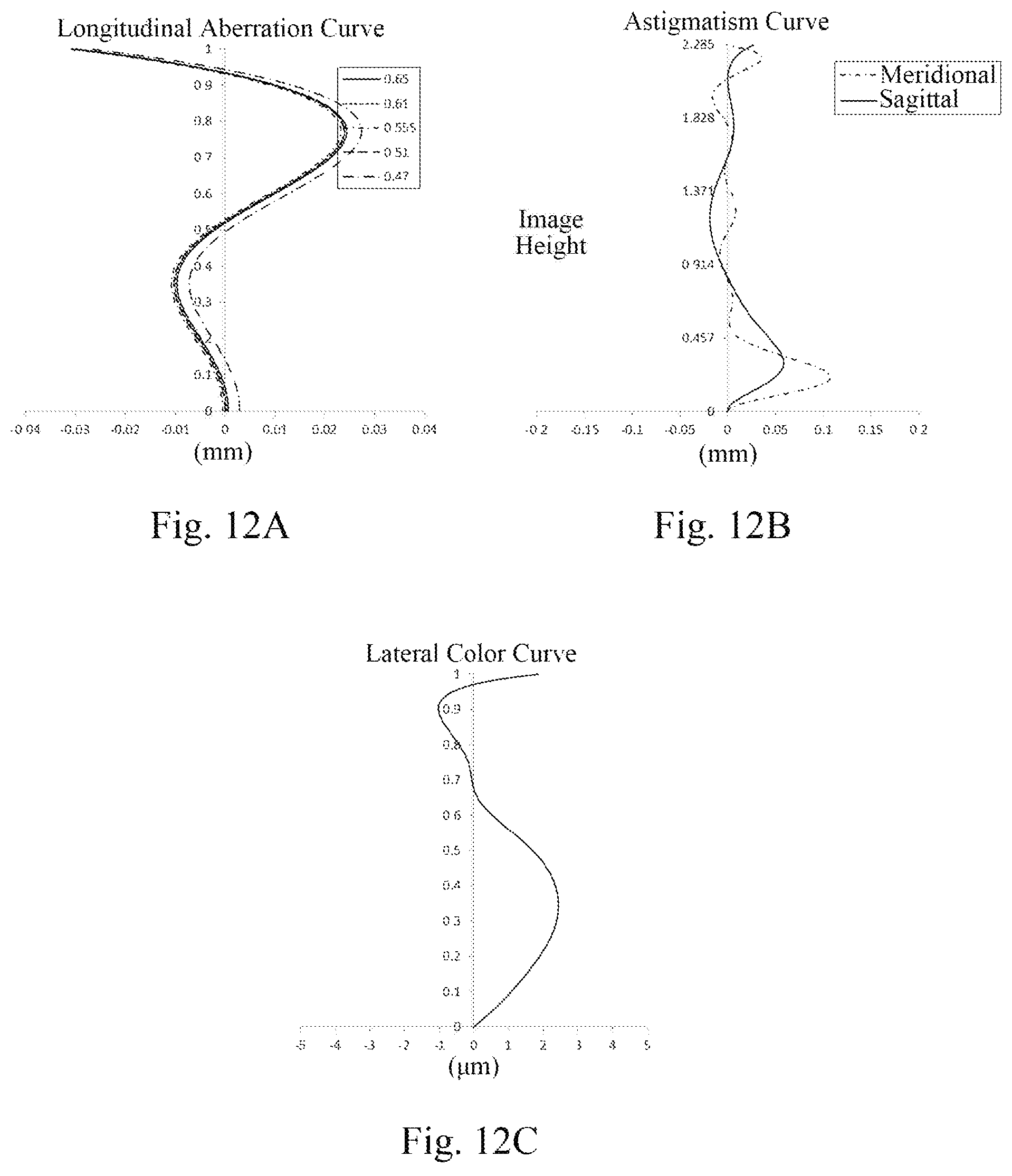
FIG. 12A illustrates a longitudinal aberration curve of the camera lens assembly according to Embodiment 6;
FIG. 12B illustrates an astigmatism curve of the camera lens assembly according to Embodiment 6;
FIG. 12C illustrates a lateral color curve of the camera lens assembly according to Embodiment 6;
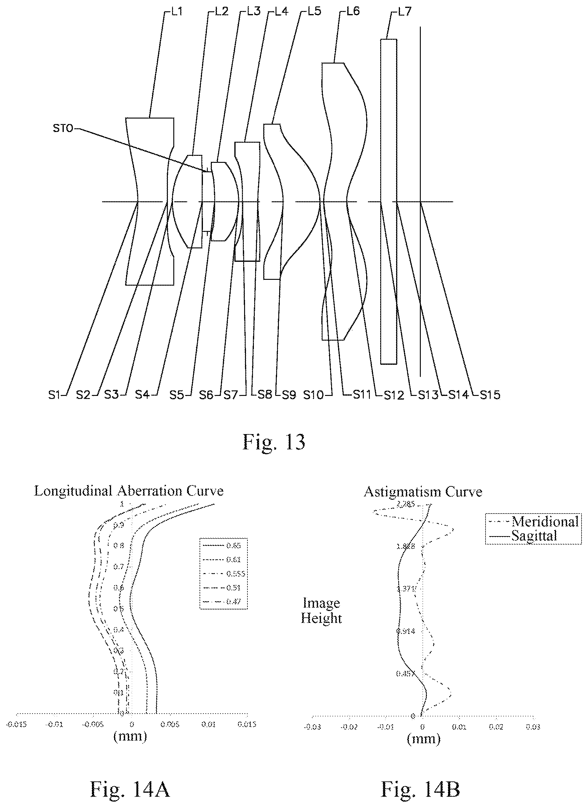
FIG. 13 is a schematic structural diagram of a camera lens assembly according to Embodiment 7 of the present application;
FIG. 14A illustrates a longitudinal aberration curve of the camera lens assembly according to Embodiment 7;
FIG. 14B illustrates an astigmatism curve of the camera lens assembly according to Embodiment 7;
FIG. 14C illustrates a lateral color curve of the camera lens assembly according to Embodiment 7;
FIG. 15 is a schematic structural diagram of a camera lens assembly according to Embodiment 8 of the present application;
FIG. 16A illustrates a longitudinal aberration curve of the camera lens assembly according to Embodiment 8;
FIG. 16B illustrates an astigmatism curve of the camera lens assembly according to Embodiment 8; and
FIG. 16C illustrates a lateral color curve of the camera lens assembly according to Embodiment 8.
DETAILED DESCRIPTION OF EMBODIMENTS
Various aspects of the present application will be described in more detail with reference to the accompanying drawings, so as to better understand the present application. It should be appreciated that the detailed description is merely an explanation for the exemplary embodiments of the present application, rather than a limitation to the scope of the present application in any way. The same reference numerals designate the same elements throughout this specification. The statement "and/or" includes any and all combinations of one or more of the associated listed items.
It should be noted that, in the Specification, statements, such as "first" and "second" are merely used to distinguish one characteristic from another characteristic, not to represent any limitations to characteristics. Thus, a first lens discussed below also could be termed a second lens without departing from the teachings of the present application.
In the accompanying drawings, for the convenience of description, thicknesses, dimensions and shapes of lenses have been slightly exaggerated. Specifically, spherical or aspheric shapes shown in the accompanying drawings are illustrated as examples. That is, spherical or aspheric shapes are not limited to the spherical or aspheric shapes shown in the accompanying drawings. The accompanying drawings are merely examples, not strictly drawn to scale.
In addition, an area near an axis indicates an area near an optical axis. The first lens is a lens closest to an object, and a sixth lens is a lens closest to a photosensitive element. In the present application, a surface closest to the object in each lens is referred to as an object side surface, and a surface closest to an image plane in each lens is referred to as an image side surface.
It will be further understood that the terms "comprising," "including," "having" and variants thereof, when used in this specification, specify the presence of stated characteristics, entireties, steps, operations, elements and/or components, but do not exclude the presence or addition of one or more other characteristics, entireties, steps, operations, elements, components and/or combinations thereof. In addition, expressions, such as "at least one of," when preceding a list of elements, modify the entire list of elements rather than an individual element in the list. Further, the use of "may," when describing embodiments of the present application, relates to "one or more embodiments of the present application." Also, the term "exemplary" is intended to refer to an example or illustration.
Unless otherwise defined, all terms (including technical and scientific terms) used herein have the same meaning as commonly understood by those of ordinary skill in the art to which the present application belongs. It will be further understood that terms, such as those defined in commonly used dictionaries, should be interpreted as having a meaning that is consistent with their meaning in the context of the relevant art and will not be interpreted in an idealized or overly formal sense unless expressly so defined herein.
Characteristics, principles and other aspects of the present application will be described below in detail.
A camera lens assembly according to an exemplary embodiment of the present application has a total effective focal length f, and may include a first lens, multiple subsequent lenses and a photosensitive element arranged in sequence from an object side to an image side along an optical axis.
In an exemplary embodiment, the first lens may have a negative focal power, and an object side surface of the first lens is a concave surface. An axial distance from the object side surface of the first lens to an image plane along the optical axis TTL and ImgH, ImgH being half a diagonal length of an effective pixel area of the electronic photosensitive element, may satisfy: 1.5<TTL/ImgH<1.7, for example, 1.583.ltoreq.TTL/ImgH.ltoreq.1.660. By reasonably setting the axial distance from the object side surface of the first lens to the image plane TTL, a total track length of the lens assembly can be restricted within a short range to ensure miniaturization of the system, so as to be used in a thin mobile phone lens. In a situation where a length of the system is less than the range, image quality is rapidly destroyed as the length of the system continues to decrease; and in a situation where the length of the system is greater than the range, an advantage of the lens assembly as an ultra-thin lens assembly applied in the mobile phone is lost.
In the exemplary embodiment, the multiple subsequent lenses may include a second lens and a third lens arranged in sequence from an image side surface of the first lens along the optical axis. An image side surface of the second lens may be a concave surface. The third lens may have a positive focal power and an effective focal length f3, an object side surface of the third lens may be a concave surface, and an image side surface of the third lens may be a convex surface. In application, thicknesses of the various lenses may be optimized. For instance, a center thickness of the second lens on the optical axis CT2 and a center thickness of the third lens on the optical axis CT3 may satisfy: 1<CT2/CT3<1.5, for example, 1.028.ltoreq.CT2/CT3.ltoreq.1.424. By reasonably distributing the center thicknesses of the second lens and the third lens CT2 and CT3, it can be ensured that the optical system has a small length, thereby ensuring the miniaturization of the camera lens assembly.
In the exemplary embodiment, the multiple subsequent lenses may further include a fourth lens arranged at the image side surface of the third lens. An axial spacing distance between the third lens and the fourth lens may be defined as T34. The fourth lens may have a negative focal power and an effective focal length f4. An object side surface of the fourth lens may be a concave surface. The effective focal length of the fourth lens f4 and the total effective focal length of the camera lens assembly f may satisfy: -2<f4/f<-1, for example, -1.573.ltoreq.f4/f.ltoreq.-1.336. As known by those skilled in the art, a spherical aberration is one of the most important factors which limit the resolution of the lens. In the present application, the fourth lens is configured to have a certain negative focal power, so that the spherical aberration can be effectively corrected, thereby improving the resolution of the camera lens assembly.
In another exemplary embodiment, the multiple subsequent lenses may further include a fifth lens and a sixth lens arranged in sequence from the image side surface of the third lens along the optical axis. In practice, axial spacing distances between various lenses may be optimized. For instance, the axial spacing distance between the third lens and the fourth lens T34 and an axial spacing distance between the fifth lens and the sixth lens T56 may satisfy: 0.5<T34/T56<1.2, for example, 0.633.ltoreq.T34/T56.ltoreq.1.118. By reasonably setting the axial spacing distances between the various lenses, a third-order aberration can be corrected while ensuring the miniaturization of the camera lens assembly, thereby improving the image quality.
The fifth lens may have a positive focal power and an effective focal length f5. An object side surface of the fifth lens may be a concave surface, and an image side surface of the fifth lens may be a convex surface. The effective focal length of the fifth lens f5 and the effective focal length of the third lens f3 may satisfy: 0.4<f3/f5<1, for example, 0.458.ltoreq.f3/f5.ltoreq.0.915, so that light can be smoothly deflected to the image plane to balance the aberration, thereby effectively improving the image quality.
In order to ensure that the camera lens assembly can be easily processed and formed, the shape of the fifth lens is required to be reasonably configured. For instance, an axial distance between an intersection point of the object side surface of the fifth lens and the optical axis and a vertex of an effective radius of the object side surface of the fifth lens SAG51 and the axial distance from the object side surface of the first lens to the image plane TTL may satisfy: -0.2<SAG51/TTL<-0.1, for example, -0.144.ltoreq.SAG51/TTL.ltoreq.-0.119.
By reasonably setting a radius of curvature of the object side surface of the fifth lens R9 and a radius of curvature of the image side surface of the fifth lens R10, the spherical aberration of the fifth lens can be corrected, which can effectively ensure the image quality of the camera lens assembly. The radius of curvature of the object side surface of the fifth lens R9 and the radius of curvature of the image side surface of the fifth lens R10 may satisfy: 1<R9/R10<1.5, for example, 1.166.ltoreq.R9/R10.ltoreq.1.419.
In addition, the first lens and the fifth lens may also be set, so that an effective radius of the object side surface of the first lens DT11 and an effective radius of the image side surface of the fifth lens DT52 satisfy: 0.5<DT11/DT52<1.2, for example, 0.608.ltoreq.DT11/DT52.ltoreq.1.150. The effective radius of the image side surface of the fifth lens and the effective radius of the object side surface of the first lens are reasonably set, which can effectively correct the distortion, and is conducive to the forming of the camera lens assembly at the same time, so that surface accuracy is ensured.
In the specific application, a half of a maximum field-of-view angle HFOV of the camera lens assembly according to the present application may further be set to HFOV>50.degree.. Accordingly, by reasonably distributing focal powers and surface forms of the lenses, the viewing angle of the camera lens assembly is effectively increased, and thus, the miniaturization of the lens assembly is ensured and the image quality is improved.
The camera lens assembly according to the embodiments of the present application may include multiple lenses, for example, the six lenses described above. By reasonably distributing focal powers and surface forms of various lenses, axial spacing distances between various lenses, and so on, the viewing angle of the camera lens assembly can be effectively increased to ensure the miniaturization of the lens assembly and improve the image quality, so that the camera lens assembly is more conducive to production and processing and can be applied to portable electronic products. In the embodiments of the present application, at least one of mirror surfaces of the lenses is an aspheric mirror surface. An aspheric lens is characterized in that its curvature continuously changes from the lens center to the periphery. In contrast to a spherical lens having a certain curvature from the lens center to the periphery, the aspheric lens has a better radius-of-curvature characteristic, has the advantages of reducing the distortion aberration and the astigmatism aberration, and can make the field of view wider and realer. The use of the aspheric lens can eliminate as much as possible the aberration that occurs during imaging, thereby improving the image quality.
However, it should be understood by those skilled in the art that, in a situation without departing from the technical solution sought to be protected by the present application, the number of lenses forming the lens assembly may be changed, to obtain various results and advantages described beneath. For instance, in the description of the first embodiment, a camera lens assembly having six lenses is described as an example, but the camera lens assembly is not limited to include six lenses. If necessary, the camera lens assembly may also include other numbers of lenses.
Specific embodiments applicable to the camera lens assembly of the above embodiments will be further described below with reference to FIG. 1 to FIG. 16C.
Embodiment 1
Embodiment 1 of the camera lens assembly according to the embodiments of the present application will be described below with reference to FIG. 1 to FIG. 2C.
As shown in FIG. 1, a camera lens assembly in Embodiment 1 includes a first lens L1 having an object side surface S1 and an image side surface S2, a second lens L2 having an object side surface S3 and an image side surface S4, a third lens L3 having an object side surface S5 and an image side surface S6, a fourth lens L4 having an object side surface S7 and an image side surface S8, a fifth lens L5 having an object side surface S9 and an image side surface S10, and a sixth lens L6 having an object side surface S11 and an image side surface S12. The camera lens assembly may further include a diaphragm (unshown) and a filter L7 having an object side surface S13 and an image side surface S14 and used for filtering out infrared light. In the camera lens assembly of this embodiment, an aperture STO may further be arranged to adjust the amount of light admitted. Light from an object sequentially passes through the surfaces S1 to S14 and finally forms an image on an image plane S15.
Table 1 below shows effective focal lengths of the lenses f1 to f6, a total effective focal length of the camera lens assembly f, a total track length of the camera lens TTL, and a half of a maximum field-of-view angle HFOV of the camera lens assembly in Embodiment 1.
Referring to Table 1, an effective focal length of the third lens L3 f3 and an effective focal length of the fifth lens L5 f5 may satisfy f3/f5=0.799. An effective focal length of the fourth lens L4 f4 and the total effective focal length of the camera lens assembly f may satisfy f4/f=-1.588. The half of the maximum field-of-view angle HFOV of the camera lens assembly may be set to HFOV=60.003.degree..
TABLE-US-00001 TABLE 1 f1 (mm) -4.18 f (mm) 1.81 f2 (mm) 2.37 Fno 2.50 f3 (mm) 1.86 TTL (mm) 3.69 f4 (mm) -2.83 HFOV (.degree.) 60.003 f5 (mm) 2.33 f6 (mm) -4.26
Table 2 shows a surface form, a radius of curvature, a thickness, a material and a conic constant of each lens in this embodiment. Table 3 shows high-order coefficients A.sub.4, A.sub.6, A.sub.8, A.sub.10, A.sub.12, A.sub.16 and A.sub.18 applicable to the aspheric surfaces S1-S12 of the aspheric lenses in this embodiment.
TABLE-US-00002 TABLE 2 surface surface radius of conic number form curvature thickness material constant OBJ spherical infinite infinite S1 aspheric -1.6115 0.3725 1.544/56.11 -13.1237 S2 aspheric -5.9278 0.0556 -93.9130 S3 aspheric 1.0460 0.3621 1.544/56.11 0.5667 S4 aspheric 4.8181 0.0739 -76.9377 STO spherical infinite 0.0784 S5 aspheric -4.9767 0.3522 1.544/56.11 69.8514 S6 aspheric -0.8662 0.0500 -1.7153 S7 aspheric -7.6598 0.2003 1.651/21.52 -62.7705 S8 aspheric 2.4729 0.2968 -0.2710 S9 aspheric -0.8419 0.5052 1.544/56.11 -3.8415 S10 aspheric -0.6145 0.0500 -1.7589 S11 aspheric 0.8343 0.3000 1.535/55.8 -2.0198 S12 aspheric 0.5344 0.4597 -3.0175 S13 spherical infinite 0.2100 S14 spherical infinite 0.3231 S15 spherical infinite
Referring to Table 2 and Table 3, a center thickness of the second lens L2 on the optical axis CT2 and a center thickness of the third lens L3 on the optical axis CT3 satisfy: CT2/CT3=1.028. A radius of curvature of the object side surface S9 of the fifth lens R9 and a radius of curvature of the image side surface S10 of the fifth lens R10 satisfy: R9/R10=1.370.
TABLE-US-00003 TABLE 3 surface number A4 A6 A8 A10 A12 A14 A16 A18 S1 2.6389E-01 -7.1287E-01 1.3916E+00 -1.9015E+00 1.7904E+00 -1.0946E+00 3- .8814E-01 -6.0288E-02 S2 1.4224E+00 -9.2565E+00 4.5454E+01 -1.5545E+02 3.5934E+02 -5.2582E+02 4- .3656E+02 -1.5530E+02 S3 9.0054E-01 -9.6856E+00 5.8831E+01 -2.3937E+02 6.2446E+02 -9.2459E+02 5- .6473E+02 0.0000E+00 S4 9.6315E-02 -4.0693E-01 -2.7420E+00 4.4751E+01 -3.1293E+02 8.8750E+02 -8.8919E+02 0.0000E+00 S5 -3.6015E-01 -1.5037E+00 1.1638E+01 -2.3663E+02 2.0722E+03 -9.7481E+03 1- .8234E+04 0.0000E+00 S6 -5.7870E-01 3.8650E-01 6.5744E-01 -5.1917E+01 3.4511E+02 -1.0927E+03 1.2872E+03 0.000- 0E+00 S7 -9.4547E-01 2.4951E+00 -1.2486E+01 5.5808E+01 -1.6961E+02 3.1686E+02 -2.7944E+02 0.0000E+00 S8 -6.2083E-01 1.3250E+00 -3.3444E+00 6.8775E+00 -1.0515E+01 1.1382E+01 -5.7592E+00 0.0000E+00 S9 7.4773E-02 -1.9764E+00 1.0729E+01 -2.1760E+01 1.6658E+01 5.1586E+00 -1.4508E+01 5.7764E+00 S10 -1.2278E-01 -8.9754E-01 4.6535E+00 -1.4247E+01 3.0938E+01 -3.7545E+01 - 2.2635E+01 -5.3238E+00 S11 -8.3790E-01 8.6289E-01 -5.4325E-01 1.8165E-01 -6.2297E-03 -1.6251E-02 4.8740E-03 -4.5176E-04 S12 -4.6756E-01 5.3653E-01 -4.4753E-01 2.5759E-01 -9.9906E-02 2.4213E-02 -3.2447E-03 1.8198E-04
In this embodiment, an axial distance from the object side surface of the first lens L1 to the image plane along the optical axis TTL and ImgH, ImgH being half a diagonal length of an effective pixel area of the electronic photosensitive element, satisfy: TTL/ImgH=1.615. An axial spacing distance between the third lens L3 and the fourth lens L4 T34 and an axial spacing distance between the fifth lens L5 and the sixth lens L6 T56 satisfy: T34/T56=1. An axial distance between an intersection point of the object side surface of the fifth lens and the optical axis and a vertex of an effective radius of the object side surface of the fifth lens SAG51 and the axial distance from the object side surface of the first lens to the image plane TTL satisfy: SAG51/TTL=-0.137. An effective radius of the object side surface S1 of the first lens DT11 and an effective radius of the image side surface S10 of the fifth lens DT52 satisfy: DT11/DT52=1.058.
FIG. 2A illustrates a longitudinal aberration curve of the camera lens assembly according to Embodiment 1, representing deviations of focal points of light in different wavelengths converged after passing through an optical system. FIG. 2B illustrates an astigmatism curve of the camera lens assembly according to Embodiment 1, representing a curvature of a meridional image plane and a curvature of a sagittal image plane. FIG. 2C illustrates a lateral color curve of the camera lens assembly according to Embodiment 1, representing deviations of different image heights on an image plane after light passes through the camera lens assembly. It can be seen from FIG. 2A to FIG. 2C that the camera lens assembly provided in Embodiment 1 can achieve good image quality.
Embodiment 2
Embodiment 2 according to the above camera lens assembly of the present application is described below with reference to FIG. 3 to FIG. 4C. Except parameters of each lens of the camera lens assembly, for example, a radius of curvature, thickness, material, conic constant, effective focal length and axial spacing of each lens, and a high-order coefficient of each mirror surface, the arrangement of the camera lens assembly described in Embodiment 2 and the following embodiments is the same as that in Embodiment 1. For the purpose of brevity, the description of parts similar to those in Embodiment 1 will be omitted.
FIG. 3 is a schematic structural diagram of a camera lens assembly according to Embodiment 2. As shown in FIG. 3, the camera lens assembly according to Embodiment 2 includes a first lens to a sixth lens L1-L6 respectively having an object side surface, and an image side surface.
Table 4 below shows effective focal lengths of the lenses f1 to f6, a total effective focal length of the camera lens assembly f, a total track length of the camera lens TTL and a half of a maximum field-of-view angle HFOV of the camera lens assembly in Embodiment 2.
TABLE-US-00004 TABLE 4 f1 (mm) -2.90 f (mm) 1.88 f2 (mm) 1.68 Fno 2.54 f3 (mm) 2.06 TTL (mm) 3.65 f4 (mm) -2.75 HFOV (.degree.) 59.884 f5 (mm) 3.04 f6 (mm) -5.14
Referring to Table 4, an effective focal length of the third lens L3 f3 and an effective focal length of the fifth lens L5 f5 may satisfy f3/f5=0.679. An effective focal length of the fourth lens L4 f4 and the total effective focal length of the camera lens assembly f may satisfy f4/f=-1.457. The half of the maximum field-of-view angle HFOV of the camera lens assembly may be set to HFOV=59.884.degree..
Table 5 shows a surface form, a radius of curvature, a thickness, a material and a conic constant of each lens in this embodiment. Table 6 shows high-order coefficients A.sub.4, A.sub.6, A.sub.8, A.sub.10, A.sub.12, A.sub.16 and A.sub.18 applicable to the aspheric surfaces S1-S12 of the aspheric lenses in this embodiment.
Referring to Table 5 and Table 6, a center thickness of the second lens L2 on the optical axis CT2 and a center thickness of the third lens L3 on the optical axis CT3 satisfy CT2/CT3=1.317. A radius of curvature of the object side surface S9 of the fifth lens R9 and a radius of curvature of the image side surface S10 of the fifth lens R10 satisfy R9/R10=1.255.
TABLE-US-00005 TABLE 5 surface surface radius of conic number form curvature thickness material constant OBJ spherical infinite infinite S1 aspheric -1.3622 0.3762 1.544/56.11 -11.3142 S2 aspheric -10.6811 0.0541 79.4717 S3 aspheric 0.8802 0.4099 1.544/56.11 -0.0499 S4 aspheric 18.1358 0.0629 -95.0000 STO spherical infinite 0.0973 S5 aspheric -3.6761 0.3113 1.544/56.11 25.2468 S6 aspheric -0.8878 0.0500 -0.9878 S7 aspheric -5.0107 0.2000 1.651/21.52 66.8369 S8 aspheric 2.8579 0.3180 -1.7256 S9 aspheric -0.8318 0.4631 1.544/56.11 -3.6482 S10 aspheric -0.6630 0.0500 -1.6113 S11 aspheric 0.8684 0.3000 1.535/55.8 -1.8725 S12 aspheric 0.5809 0.4406 -2.6529 S13 spherical infinite 0.2100 1.517/64.17 S14 spherical infinite 0.3073 S15 spherical infinite
In this embodiment, an axial distance from the object side surface of the first lens L1 to the image plane along the optical axis TTL and ImgH, ImgH being half a diagonal length of an effective pixel area of the electronic photosensitive element, satisfy TTL/ImgH=1.601. An axial spacing distance between the third lens L3 and the fourth lens L4 T34 and an axial spacing distance between the fifth lens L5 and the sixth lens L6 T56 satisfy T34/T56=1. An axial distance between an intersection point of the object side surface of the fifth lens and the optical axis and a vertex of an effective radius of the object side surface of the fifth lens SAG51 and the axial distance from the object side surface of the first lens to the image plane TTL satisfy SAG51/TTL=-0.140. An effective radius of the object side surface S1 of the first lens DT11 and an effective radius of the image side surface S10 of the fifth lens DT52 satisfy DT11/DT52=1.082.
TABLE-US-00006 TABLE 6 surface number A4 A6 A8 A10 A12 A14 A16 A18 S1 1.4446E-01 -2.7709E-01 4.6887E-01 -5.4289E-01 4.0638E-01 -1.7522E-01 3- .3411E-02 -6.3844E-04 S2 8.8748E-01 -4.4453E+00 2.2580E+01 -8.2701E+01 2.1576E+02 -3.7165E+02 3- .7868E+02 -1.6992E+02 S3 2.1963E-01 -3.1884E+00 1.6077E+01 -3.9930E+01 2.6507E+01 8.7368E+01 -1.3961E+02 0.0000E+00 S4 -3.9739E-02 -1.5971E-01 -7.5945E-02 1.0151E+00 -1.2475E+00 5.8515E-01 -9.7371E-02 0.0000E+00 S5 -2.6992E-01 -9.8511E-01 -6.0480E+00 5.2683E+01 -2.5543E+02 -1.0529E+02 2.2048E+03 0.0000E+00 S6 -1.3573E-01 -2.3942E+00 1.9187E+01 -1.7643E+02 9.7526E+02 -2.8743E+03 3- .3787E+03 0.0000E+00 S7 -5.6830E-01 -6.4090E-01 4.9951E+00 -2.4483E+01 9.5805E+01 -1.9534E+02 1- .3615E+02 0.0000E+00 S8 -5.4750E-01 7.9971E-01 -1.7061E+00 4.0680E+00 -6.0927E+00 6.2136E+00 -3.3374E+00 0.0000E+00 S9 1.0385E-02 -2.7217E+00 1.2897E+01 -2.6799E+01 3.3156E+01 -2.4901E+01 1- .0224E+01 -1.7361E+00 S10 -1.0742E-01 -1.0467E+00 4.7877E+00 -1.5514E+01 3.6295E+01 -4.6127E+01 - 2.8775E+01 -6.9824E+00 S11 -8.3495E-01 4.7801E-01 2.8433E-01 -6.2492E-01 4.3129E-01 -1.5298E-01 2.8015E-02 -2.10- 16E-03 S12 -5.5582E-01 6.0125E-01 -4.6713E-01 2.4543E-01 -8.1413E-02 1.4142E-02 -6.6661E-04 -6.9308E-05
FIG. 4A illustrates a longitudinal aberration curve of the camera lens assembly according to Embodiment 2, representing deviations of focal points of light in different wavelengths converged after passing through an optical system. FIG. 4B illustrates an astigmatism curve of the camera lens assembly according to Embodiment 2, representing a curvature of a meridional image plane and a curvature of a sagittal image plane. FIG. 4C illustrates a lateral color curve of the camera lens assembly according to Embodiment 2, representing deviations of different image heights on an image plane after light passes through the camera lens assembly. It can be seen from FIG. 4A to FIG. 4C that the camera lens assembly provided in Embodiment 2 can achieve good image quality.
Embodiment 3
Embodiment 3 according to the above camera lens assembly of the present application will be described below with reference to FIG. 5 to FIG. 6C. FIG. 5 is a schematic structural diagram of a camera lens assembly according to Embodiment 3 of the present application. As shown in FIG. 5, the camera lens assembly according to Embodiment 3 includes a first lens to a sixth lens L1-L6 respectively having an object side surface, and an image side surface.
Table 7 below shows effective focal lengths of the lenses f1 to f6, a total effective focal length of the camera lens assembly f, a total track length of the camera lens TTL and a half of a maximum field-of-view angle HFOV of the camera lens assembly in Embodiment 3.
Referring to Table 7, an effective focal length of the third lens L3 f3 and an effective focal length of the fifth lens L5 f5 may satisfy f3/f5=0.702. An effective focal length of the fourth lens L4 f4 and the total effective focal length of the camera lens assembly f may satisfy f4/f=-1.408. The half of the maximum field-of-view angle HFOV of the camera lens assembly may be set to HFOV=59.889.degree..
TABLE-US-00007 TABLE 7 f1 (mm) -2.86 f (mm) 1.88 f2 (mm) 1.63 Fno 2.53 f3 (mm) 2.04 TTL (mm) 3.64 f4 (mm) -2.65 HFOV (.degree.) 59.889 f5 (mm) 2.90 f6 (mm) -4.70
Table 8 shows a surface form, a radius of curvature, a thickness, a material and a conic constant of each lens in this embodiment. Table 9 shows high-order coefficients A.sub.4, A.sub.6, A.sub.8, A.sub.10, A.sub.12, A.sub.16 and A.sub.18 applicable to the aspheric surfaces S1-S12 of the aspheric lenses in this embodiment.
Referring to Table 8 and Table 9, a center thickness of the second lens L2 on the optical axis CT2 and a center thickness of the third lens L3 on the optical axis CT3 satisfy CT2/CT3=1.400. A radius of curvature of the object side surface S9 of the fifth lens R9 and a radius of curvature of the image side surface S10 of the fifth lens R10 satisfy R9/R10=1.259.
TABLE-US-00008 TABLE 8 surface surface radius of conic number form curvature thickness material constant OBJ spherical infinite infinite S1 aspheric -1.3569 0.3734 1.544/56.11 -11.3505 S2 aspheric -11.2388 0.0518 -10.7734 S3 aspheric 0.8798 0.4151 1.544/56.11 -0.1448 S4 aspheric 68.1962 0.0655 95.0000 STO spherical infinite 0.1034 S5 aspheric -3.2513 0.2965 1.544/56.11 27.6669 S6 aspheric -0.8556 0.0500 -1.3010 S7 aspheric -4.2561 0.2000 1.651/21.52 -3.3675 S8 aspheric 3.0032 0.3064 -1.6824 S9 aspheric -0.8240 0.4831 1.544/56.11 -3.7332 S10 aspheric -0.6543 0.0500 -1.6097 S11 aspheric 0.9022 0.3000 1.535/55.8 -1.8755 S12 aspheric 0.5875 0.4365 -2.6798 S13 spherical infinite 0.2100 1.517/64.17 S14 spherical infinite 0.3032 S15 spherical infinite
In this embodiment, an axial distance from the object side surface of the first lens L1 to the image plane along the optical axis TTL and ImgH, ImgH being half a diagonal length of an effective pixel area of the electronic photosensitive element, satisfy TTL/ImgH=1.599. An axial spacing distance between the third lens L3 and the fourth lens L4 T34 and an axial spacing distance between the fifth lens L5 and the sixth lens L6 T56 satisfy T34/T56=1. An axial distance between an intersection point of the object side surface of the fifth lens and the optical axis and a vertex of an effective radius of the object side surface of the fifth lens SAG51 and the axial distance from the object side surface of the first lens to the image plane TTL satisfy SAG51/TTL=-0.142. An effective radius of the object side surface S1 of the first lens DT11 and an effective radius of the image side surface S10 of the fifth lens DT52 satisfy DT11/DT52=1.069.
TABLE-US-00009 TABLE 9 surface number A4 A6 A8 A10 A12 A14 A16 A18 S1 1.4800E-01 -2.9010E-01 4.9138E-01 -5.5453E-01 3.9484E-01 -1.5623E-01 2- .3713E-02 1.1707E-03 S2 9.4112E-01 -4.7952E+00 2.4133E+01 -8.7244E+01 2.2646E+02 -3.9161E+02 4- .0362E+02 -1.8441E+02 S3 2.8150E-01 -3.3965E+00 1.5728E+01 -2.9620E+01 -2.8769E+01 2.2103E+02 -2.8285E+02 0.0000E+00 S4 -5.0927E-02 -4.4316E-01 3.6254E+00 -2.8974E+01 1.2287E+02 -2.8844E+02 2- .6811E+02 0.0000E+00 S5 -2.5285E-01 -4.7337E-01 -1.5738E+01 1.5977E+02 -8.9602E+02 1.8243E+03 3.5758E+01 0.0000E+00 S6 -3.2796E-02 -4.8694E+00 5.2851E+01 -4.6089E+02 2.3640E+03 -6.4791E+03 7- .2489E+03 0.0000E+00 S7 -5.5936E-01 -1.7262E+00 1.4207E+01 -7.9585E+01 2.7297E+02 -4.8105E+02 2- .8824E+02 0.0000E+00 S8 -5.7804E-01 9.2619E-01 -1.8814E+00 3.6386E+00 -3.6078E+00 2.0410E+00 -9.5274E-01 0.0000E+00 S9 -5.7374E-02 -2.5428E+00 1.3321E+01 -2.8525E+01 3.5208E+01 -2.5979E+01 1- .0457E+01 -1.7466E+00 S10 -1.1987E-01 -8.5164E-01 3.4418E+00 -1.0490E+01 2.6212E+01 -3.5172E+01 - 2.2678E+01 -5.6168E+00 S11 -8.3153E-01 4.1252E-01 4.6066E-01 -8.4863E-01 5.8545E-01 -2.1214E-01 3.9921E-02 -3.08- 31E-03 S12 -5.7251E-01 6.3574E-01 -5.0764E-01 2.7489E-01 -9.4451E-02 1.7256E-02 -9.7499E-04 -6.6872E-05
FIG. 6A illustrates a longitudinal aberration curve of the camera lens assembly according to Embodiment 3, representing deviations of focal points of light in different wavelengths converged after passing through an optical system. FIG. 6B illustrates an astigmatism curve of the camera lens assembly according to Embodiment 3, representing a curvature of a meridional image plane and a curvature of a sagittal image plane. FIG. 6C illustrates a lateral color curve of the camera lens assembly according to Embodiment 3, representing deviations of different image heights on an image plane after light passes through the camera lens assembly. It can be seen from FIG. 6A to FIG. 6C that the camera lens assembly provided in Embodiment 3 can achieve good image quality.
Embodiment 4
Embodiment 4 according to the above camera lens assembly of the present application will be described below with reference to FIG. 7 to FIG. 8C. FIG. 7 is a schematic structural diagram of a camera lens assembly according to Embodiment 4 of the present application. As shown in FIG. 7, the camera lens assembly according to Embodiment 4 includes a first lens to a sixth lens L1-L6 respectively having an object side surface, and an image side surface.
Table 10 below shows effective focal lengths of the lenses f1 to f6, a total effective focal length of the camera lens assembly f, a total track length of the camera lens TTL and a half of a maximum field-of-view angle HFOV of the camera lens assembly in Embodiment 4.
TABLE-US-00010 TABLE 10 f1 (mm) -2.73 f (mm) 1.88 f2 (mm) 1.58 Fno 2.53 f3 (mm) 2.09 TTL (mm) 3.65 f4 (mm) -2.71 HFOV (.degree.) 60.005 f5 (mm) 2.94 f6 (mm) -4.83
Referring to Table 10, an effective focal length of the third lens L3 f3 and an effective focal length of the fifth lens L5 f5 may satisfy f3/f5=0.709. An effective focal length of the fourth lens L4 f4 and the total effective focal length of the camera lens assembly f may satisfy f4/f=-1.437. The half of the maximum field-of-view angle HFOV of the camera lens assembly may be set to HFOV=60.005.degree..
Table 11 shows a surface form, a radius of curvature, a thickness, a material and a conic constant of each lens in this embodiment. Table 12 shows high-order coefficients A.sub.4, A.sub.6, A.sub.8, A.sub.10, A.sub.12, A.sub.16 and A.sub.18 applicable to the aspheric surfaces S1-S12 of the aspheric lenses in this embodiment.
Referring to Table 11 and Table 12, a center thickness of the second lens L2 on the optical axis CT2 and a center thickness of the third lens L3 on the optical axis CT3 satisfy CT2/CT3=1.424. A radius of curvature of the object side surface S9 of the fifth lens R9 and a radius of curvature of the image side surface S10 of the fifth lens R10 satisfy R9/R10=1.254.
TABLE-US-00011 TABLE 11 surface surface radius of conic number form curvature thickness material constant OBJ spherical infinite infinite S1 aspheric -1.3464 0.3703 1.544/56.11 -11.6584 S2 aspheric -15.1731 0.0500 -24.0654 S3 aspheric 0.8560 0.4242 1.544/56.11 -0.1287 S4 aspheric 108.0227 0.0621 -95.0000 STO spherical infinite 0.1060 S5 aspheric -3.1276 0.2979 1.544/56.11 29.5155 S6 aspheric -0.8626 0.0500 -1.1074 S7 aspheric -4.0845 0.2000 1.651/21.52 4.1158 S8 aspheric 3.2044 0.2991 -2.1626 S9 aspheric -0.8251 0.4838 1.544/56.11 -3.7792 S10 aspheric -0.6578 0.0500 -1.6039 S11 aspheric 0.8911 0.3000 1.535/55.8 -1.7815 S12 aspheric 0.5851 0.4385 -2.6172 S13 spherical infinite 0.2100 1.517/64.17 S14 spherical infinite 0.3052 S15 spherical infinite
In this embodiment, an axial distance from the object side surface of the first lens L1 to the image plane along the optical axis TTL and ImgH, ImgH being half a diagonal length of an effective pixel area of the electronic photosensitive element, satisfy TTL/ImgH=1.596. An axial spacing distance between the third lens L3 and the fourth lens L4 T34 and an axial spacing distance between the fifth lens L5 and the sixth lens L6 T56 satisfy T34/T56=1. An axial distance between an intersection point of the object side surface of the fifth lens and the optical axis and a vertex of an effective radius of the object side surface of the fifth lens SAG51 and the axial distance from the object side surface of the first lens to the image plane TTL satisfy SAG51/TTL=-0.142. An effective radius of the object side surface S1 of the first lens DT11 and an effective radius of the image side surface S10 of the fifth lens DT52 satisfy DT11/DT52=1.057.
TABLE-US-00012 TABLE 12 surface number A4 A6 A8 A10 A12 A14 A16 A18 S1 1.4053E-01 -2.6281E-01 4.2243E-01 -4.4294E-01 2.7908E-01 -8.3618E-02 -- 7.8064E-04 4.4890E-03 S2 8.8523E-01 -4.4949E+00 2.3079E+01 -8.5187E+01 2.2444E+02 -3.8934E+02 3- .9695E+02 -1.7720E+02 S3 2.0583E-01 -3.0788E+00 1.6129E+01 -4.3389E+01 5.1015E+01 2.1749E+01 -8.4459E+01 0.0000E+00 S4 -3.2738E-02 -3.8317E-01 2.9344E+00 -1.5112E+01 3.5207E+01 -3.5750E+01 1- .3074E+01 0.0000E+00 S5 -2.4837E-01 -3.2793E-01 -1.7314E+01 1.8014E+02 -1.0616E+03 2.5287E+03 -1.1797E+03 0.0000E+00 S6 -1.1788E-01 -4.0026E+00 4.7526E+01 -4.4125E+02 2.3159E+03 -6.4052E+03 7- .1728E+03 0.0000E+00 S7 -6.4832E-01 -8.9759E-01 8.8343E+00 -5.6375E+01 2.0586E+02 -3.6519E+02 1- .9762E+02 0.0000E+00 S8 -5.7356E-01 9.5273E-01 -2.0273E+00 3.9888E+00 -4.1207E+00 2.4037E+00 -1.0132E+00 0.0000E+00 S9 -5.1058E-02 -2.5306E+00 1.3110E+01 -2.7690E+01 3.3497E+01 -2.4107E+01 9- .4377E+00 -1.5302E+00 S10 -1.2072E-01 -8.1936E-01 3.3089E+00 -1.0232E+01 2.5825E+01 -3.4733E+01 - 2.2397E+01 -5.5455E+00 S11 -8.3793E-01 4.0617E-01 4.6864E-01 -8.4457E-01 5.7545E-01 -2.0630E-01 3.8444E-02 -2.94- 27E-03 S12 -5.8069E-01 6.4779E-01 -5.1912E-01 2.8261E-01 -9.7828E-02 1.8178E-02 -1.1208E-03 -5.6607E-05
FIG. 8A illustrates a longitudinal aberration curve of the camera lens assembly according to Embodiment 4, representing deviations of focal points of light in different wavelengths converged after passing through an optical system. FIG. 8B illustrates an astigmatism curve of the camera lens assembly according to Embodiment 4, representing a curvature of a meridional image plane and a curvature of a sagittal image plane. FIG. 8C illustrates a lateral color curve of the camera lens assembly according to Embodiment 4, representing deviations of different image heights on an image plane after light passes through the camera lens assembly. It can be seen from FIG. 8A to FIG. 8C that the camera lens assembly provided in Embodiment 4 can achieve good image quality.
Embodiment 5
Embodiment 5 according to the above camera lens assembly of the present application will be described below with reference to FIG. 9 to FIG. 10C. FIG. 9 is a schematic structural diagram of a camera lens assembly according to Embodiment 5 of the present application. As shown in FIG. 9, the camera lens assembly according to Embodiment 5 includes a first lens to a sixth lens L1-L6 respectively having an object side surface, and an image side surface.
Table 13 below shows effective focal lengths of the lenses f1 to f6, a total effective focal length of the camera lens assembly f, a total track length of the camera lens TTL and a half of a maximum field-of-view angle HFOV of the camera lens assembly in Embodiment 5.
TABLE-US-00013 TABLE 13 f1 (mm) -3.57 f (mm) 1.88 f2 (mm) 2.05 Fno 2.53 f3 (mm) 1.96 TTL (mm) 3.62 f4 (mm) -2.57 HFOV (.degree.) 60.008 f5 (mm) 2.50 f6 (mm) -4.20
Referring to Table 13, an effective focal length of the third lens L3 f3 and an effective focal length of the fifth lens L5 f5 may satisfy f3/f5=0.786. An effective focal length of the fourth lens L4 f4 and the total effective focal length of the camera lens assembly f may satisfy f4/f=-1.363. The half of the maximum field-of-view angle HFOV of the camera lens assembly may be set to HFOV=60.008.degree..
Table 14 shows a surface form, a radius of curvature, a thickness, a material and a conic constant of each lens in this embodiment. Table 15 shows high-order coefficients A.sub.4, A.sub.6, A.sub.8, A.sub.10, A.sub.12, A.sub.16 and A.sub.18 applicable to the aspheric surfaces S1-S12 of the aspheric lenses in this embodiment.
TABLE-US-00014 TABLE 14 surface surface radius of conic number form curvature thickness material constant OBJ spherical infinite infinite S1 aspheric -1.3320 0.3100 1.544/56.11 -13.1601 S2 aspheric -4.5659 0.0659 -79.3509 S3 aspheric 1.1206 0.3594 1.544/56.11 0.8667 S4 aspheric -573.2212 0.0609 95.0000 STO spherical infinite 0.0840 S5 aspheric -5.2460 0.3060 1.544/56.11 95.0000 S6 aspheric -0.9081 0.0559 -1.1362 S7 aspheric -7.0783 0.2000 1.651/21.52 -76.1524 S8 aspheric 2.2362 0.3513 -8.2981 S9 aspheric -0.9196 0.4689 1.544/56.11 -3.1029 S10 aspheric -0.6482 0.0500 -1.6506 S11 aspheric 0.8994 0.3096 1.535/55.8 -2.0085 S12 aspheric 0.5656 0.4596 -2.7664 S13 spherical infinite 0.2100 1.517/64.17 S14 spherical infinite 0.3263 S15 spherical infinite
Referring to Table 14 and Table 15, a center thickness of the second lens L2 on the optical axis CT2 and a center thickness of the third lens L3 on the optical axis CT3 satisfy CT2/CT3=1.175. A radius of curvature of the object side surface S9 of the fifth lens R9 and a radius of curvature of the image side surface S10 of the fifth lens R10 satisfy R9/R10=1.419.
TABLE-US-00015 TABLE 15 surface number A4 A6 A8 A10 A12 A14 A16 A18 S1 1.4446E-01 -2.7375E-01 3.8131E-01 -2.8063E-01 1.0202E-01 -1.4280E-02 -- 9.8016E-04 3.7629E-04 S2 1.2772E+00 -7.2933E+00 3.7565E+01 -1.4661E+02 4.1415E+02 -7.6701E+02 8- .3141E+02 -3.9553E+02 S3 5.4397E-01 -6.2323E+00 3.3288E+01 -1.2776E+02 3.0662E+02 -3.8593E+02 1- .4634E+02 0.0000E+00 S4 -3.7371E-02 -7.8287E-01 2.2179E+00 -1.9066E+01 1.0737E+02 -3.2918E+02 3- .8380E+02 0.0000E+00 S5 -1.0157E-01 -1.7442E+00 6.4589E+00 -3.5854E+01 7.3618E+01 -1.8894E+02 8- .0331E+02 0.0000E+00 S6 2.0628E-01 -4.6103E+00 2.3336E+01 -8.7815E+01 2.4828E+02 -5.9341E+02 7- .1894E+02 0.0000E+00 S7 -3.1623E-01 -2.8219E+00 1.1888E+01 -1.7602E+00 -1.2125E+02 3.5022E+02 -3.4359E+02 0.0000E+00 S8 -3.7850E-01 1.3041E-01 7.6228E-01 -6.0372E-01 -2.9320E+00 5.6050E+00 -2.7347E+00 0.0000E+00 S9 2.4633E-01 -2.3997E+00 8.3336E+00 -1.3936E+01 1.3256E+01 -7.4588E+00 2- .3307E+00 -3.1293E-01 S10 -5.6255E-02 -8.4078E-01 3.1941E+00 -9.4029E+00 2.0374E+01 -2.3123E+01 - 1.2482E+01 -2.5568E+00 S11 -7.8359E-01 5.1492E-01 6.8897E-02 -3.6328E-01 2.7461E-01 -1.0112E-01 1.8854E-02 -1.42- 22E-03 S12 -5.2686E-01 6.0657E-01 -5.1952E-01 3.1174E-01 -1.2582E-01 3.1461E-02 -4.3069E-03 2.4440E-04
In this embodiment, an axial distance from the object side surface of the first lens L1 to the image plane along the optical axis TTL and ImgH, ImgH being half a diagonal length of an effective pixel area of the electronic photosensitive element, satisfy TTL/ImgH=1.583. An axial spacing distance between the third lens L3 and the fourth lens L4 T34 and an axial spacing distance between the fifth lens L5 and the sixth lens L6 T56 satisfy T34/T56=1.118. An axial distance between an intersection point of the object side surface of the fifth lens and the optical axis and a vertex of an effective radius of the object side surface of the fifth lens SAG51 and the axial distance from the object side surface of the first lens to the image plane TTL satisfy SAG51/TTL=-0.144. An effective radius of the object side surface S1 of the first lens DT11 and an effective radius of the image side surface S10 of the fifth lens DT52 satisfy DT11/DT52=0.608.
FIG. 10A illustrates a longitudinal aberration curve of the camera lens assembly according to Embodiment 5, representing deviations of focal points of light in different wavelengths converged after passing through an optical system. FIG. 10B illustrates an astigmatism curve of the camera lens assembly according to Embodiment 5, representing a curvature of a meridional image plane and a curvature of a sagittal image plane. FIG. 10C illustrates a lateral color curve of the camera lens assembly according to Embodiment 5, representing deviations of different image heights on an image plane after light passes through the camera lens assembly. It can be seen from FIG. 10A to FIG. 10C that the camera lens assembly provided in Embodiment 5 can achieve good image quality.
Embodiment 6
Embodiment 6 according to the above camera lens assembly of the present application will be described below with reference to FIG. 11 to FIG. 12C. FIG. 11 is a schematic structural diagram of a camera lens assembly according to Embodiment 6 of the present application. As shown in FIG. 11, the camera lens assembly according to Embodiment 6 includes a first lens to a sixth lens L1-L6 respectively having an object side surface, and an image side surface.
Table 16 below shows effective focal lengths of the lenses f1 to f6, a total effective focal length of the camera lens assembly f, a total track length of the camera lens TTL and a half of a maximum field-of-view angle HFOV of the camera lens assembly in Embodiment 6.
Referring to Table 16, an effective focal length of the third lens L3 f3 and an effective focal length of the fifth lens L5 f5 may satisfy f3/f5=0.458. An effective focal length of the fourth lens L4 f4 and the total effective focal length of the camera lens assembly f may satisfy f4/f=-1.336. The half of the maximum field-of-view angle HFOV of the camera lens assembly may be set to HFOV=60.002.degree..
TABLE-US-00016 TABLE 16 f1 (mm) -3.37 f (mm) 1.80 f2 (mm) 1.96 Fno 2.52 f3 (mm) 1.99 TTP (mm) 3.70 f4 (mm) -2.40 HFOV (.degree.) 60.002 f5 (mm) 4.34 f6 (mm) 26.24
Table 17 shows a surface form, a radius of curvature, a thickness, a material and a conic constant of each lens in this embodiment. Table 18 shows high-order coefficients A.sub.4, A.sub.6, A.sub.8, A.sub.10, A.sub.12, A.sub.16 and A.sub.18 applicable to the aspheric surfaces S1-S12 of the aspheric lenses in this embodiment.
TABLE-US-00017 TABLE 17 surface surface radius of conic number form curvature thickness material constant OBJ spherical infinite infinite S1 aspheric -1.4051 0.2716 1.544/56.11 -15.7572 S2 aspheric -6.3340 0.0553 -22.9241 S3 aspheric 1.1024 0.3662 1.544/56.11 -0.5510 S4 aspheric -29.7965 0.0500 95.0000 STO spherical infinite 0.0996 S5 aspheric -3.6304 0.2924 1.544/56.11 9.2005 S6 aspheric -0.8601 0.0501 -1.0143 S7 aspheric -2.7738 0.2000 1.651/21.52 20.8479 S8 aspheric 3.7507 0.2173 -17.8073 S9 aspheric -0.8788 0.4370 1.544/56.11 -4.3498 S10 aspheric -0.7538 0.0792 -1.8033 S11 aspheric 1.5299 0.5810 1.535/55.8 -78.5572 S12 aspheric 1.4887 0.7352 -9.5931 S13 spherical infinite 0.2100 1.517/64.17 S14 spherical infinite 0.0550 S15 spherical infinite
Referring to Table 17 and Table 18, a center thickness of the second lens L2 on the optical axis CT2 and a center thickness of the third lens L3 on the optical axis CT3 satisfy CT2/CT3=1.252. A radius of curvature of the object side surface S9 of the fifth lens R9 and a radius of curvature of the image side surface S10 of the fifth lens R10 satisfy R9/R10=1.166.
TABLE-US-00018 TABLE 18 Surface number A4 A6 A8 A10 A12 A14 A16 A18 S1 2.7891E-01 -8.0376E-01 1.7780E+00 -2.6596E+00 2.5347E+00 -1.4605E+00 4.5890E-01 -5.9568E-02 S2 1.3901E+00 -8.6478E+00 4.1855E+01 -1.2963E+02 2.6031E+02 -3.3730E+02 2.8480E+02 -1.2650E+02 S3 6.8810E-01 -1.1494E+01 8.4051E+01 -3.6598E+02 9.3396E+02 -1.2429E+03 6.3241E+02 0.0000E+00 S4 -3.8614E-01 1.6842E+00 -1.7355E+01 1.2251E+02 -4.7142E+02 8.8117E+02 -6.2602E+02 0.0000E+00 S5 -2.0767E-01 -1.9275E+00 1.3033E+01 -1.1945E+02 6.4463E+02 -1.4879E+03 1.2110E+03 0.0000E+00 S6 -2.4152E-01 9.7001E-01 1.2800E+01 -3.8390E+02 2.5694E+03 -7.2703E+03 7.5841E+03 0.0000E+00 S7 -6.3755E-01 -1.4198E+00 4.0416E+01 -4.3036E+02 1.9733E+03 -4.0638E+03 3.0841E+03 0.0000E+00 S8 -8.4411E-01 4.0464E+00 -1.7509E+01 4.6854E+01 -7.5261E+01 6.7590E+01 -2.5786E+01 0.0000E+00 S9 -1.0446E+00 6.6849E+00 -1.7199E+01 2.7978E+01 -3.1377E+01 2.2992E+01 -9.6265E+00 1.7130E+00 S10 -1.3404E+00 6.1854E+00 -1.4957E+01 1.4084E+01 1.2864E+01 -3.8062E+01 2.8505E+01 -7.2096E+00 S11 1.8317E-01 -1.9622E-01 -3.9038E-01 6.0261E-01 -3.2428E-01 8.4547E-02 -1.0791E-02 5.4047E-04 S12 8.1022E-03 -6.1766E-03 -9.1068E-02 8.8374E-02 -3.9354E-02 9.4214E-03 -1.1580E-03 5.7188E-05
In this embodiment, an axial distance from the object side surface of the first lens L1 to the image plane along the optical axis TTL and ImgH, ImgH being half a diagonal length of an effective pixel area of the electronic photosensitive element, satisfy TTL/ImgH=1.619. An axial spacing distance between the third lens L3 and the fourth lens L4 T34 and an axial spacing distance between the fifth lens L5 and the sixth lens L6 T56 satisfy T34/T56=0.633. An axial distance between an intersection point of the object side surface of the fifth lens and the optical axis and a vertex of an effective radius of the object side surface of the fifth lens SAG51 and the axial distance from the object side surface of the first lens to the image plane TTL satisfy SAG51/TTL=-0.119. An effective radius of the object side surface S1 of the first lens DT11 and an effective radius of the image side surface S10 of the fifth lens DT52 satisfy DT11/DT52=1.150.
FIG. 12A illustrates a longitudinal aberration curve of the camera lens assembly according to Embodiment 6, representing deviations of focal points of light in different wavelengths converged after passing through an optical system. FIG. 12B illustrates an astigmatism curve of the camera lens assembly according to Embodiment 6, representing a curvature of a meridional image plane and a curvature of a sagittal image plane. FIG. 12C illustrates a lateral color curve of the camera lens assembly according to Embodiment 6, representing deviations of different image heights on an image plane after light passes through the camera lens assembly. It can be seen from FIG. 12A to FIG. 12C that the camera lens assembly provided in Embodiment 6 can achieve good image quality.
Embodiment 7
Embodiment 7 according to the above camera lens assembly of the present application will be described below with reference to FIG. 13 to FIG. 14C. FIG. 13 is a schematic structural diagram of a camera lens assembly according to Embodiment 7 of the present application. As shown in FIG. 13, the camera lens assembly according to Embodiment 7 includes a first lens to a sixth lens L1-L6 respectively having an object side surface, and an image side surface.
Table 19 below shows effective focal lengths of the lenses f1 to f6, a total effective focal length of the camera lens assembly f, a total track length of the camera lens TTL and a half of a maximum field-of-view angle HFOV of the camera lens assembly in Embodiment 7.
TABLE-US-00019 TABLE 19 f1 (mm) -3.46 f (mm) 1.88 f2 (mm) 1.89 Fno 2.54 f3 (mm) 1.97 TTL (mm) 3.70 f4 (mm) -2.58 HFOV (.degree.) 60.002 f5 (mm) 2.76 f6 (mm) -4.49
Referring to Table 19, an effective focal length of the third lens L3 f3 and an effective focal length of the fifth lens L5 f5 may satisfy f3/f5=0.713. An effective focal length of the fourth lens L4 f4 and the total effective focal length of the camera lens assembly f may satisfy f4/f=-1.369. The half of the maximum field-of-view angle HFOV of the camera lens assembly may be set to HFOV=60.002.degree..
Table 20 shows a surface form, a radius of curvature, a thickness, a material and a conic constant of each lens in this embodiment. Table 21 shows high-order coefficients A.sub.4, A.sub.6, A.sub.8, A.sub.10, A.sub.12, A.sub.16 and A.sub.18 applicable to the aspheric surfaces S1-S12 of the aspheric lenses in this embodiment.
TABLE-US-00020 TABLE 20 surface surface radius of conic number form curvature thickness material constant OBJ spherical infinite infinite S1 aspheric -1.4054 0.3861 1.544/56.11 -11.3154 S2 aspheric -6.0348 0.0651 -12.5751 S3 aspheric 1.0075 0.3900 1.544/56.11 0.5777 S4 aspheric 36.3309 0.0661 -95.0000 STO spherical infinite 0.0962 S5 aspheric -3.6848 0.3145 1.544/56.11 -75.4084 S6 aspheric -0.8573 0.0500 -1.5296 S7 aspheric -6.0554 0.2000 1.651/21.52 -51.2037 S8 aspheric 2.3802 0.3337 -2.3885 S9 aspheric -0.8919 0.4804 1.544/56.11 -3.5861 S10 aspheric -0.6669 0.0500 -1.6200 S11 aspheric 0.8884 0.3000 1.535/55.8 -1.8910 S12 aspheric 0.5727 0.4434 -2.9244 S13 spherical infinite 0.2100 1.517/64.17 S14 spherical infinite 0.3101 S15 spherical infinite
Referring to Table 20 and Table 21, a center thickness of the second lens L2 on the optical axis CT2 and a center thickness of the third lens L3 on the optical axis CT3 satisfy CT2/CT3=1.240. A radius of curvature of the object side surface S9 of the fifth lens R9 and a radius of curvature of the image side surface S10 of the fifth lens R10 satisfy R9/R10=1.337.
TABLE-US-00021 TABLE 21 surface number A4 A6 A8 A10 A12 A14 A16 A18 S1 1.4012E-01 -2.5794E-01 3.8870E-01 -3.8549E-01 2.3624E-01 -7.1142E-02 -- 2.9631E-04 3.8721E-03 S2 1.1145E+00 -5.5487E+00 2.6038E+01 -9.0905E+01 2.2943E+02 -3.8627E+02 3- .8770E+02 -1.7359E+02 S3 4.6418E-01 -4.7150E+00 2.1303E+01 -5.5588E+01 4.8918E+01 9.1011E+01 -1.9732E+02 0.0000E+00 S4 -4.4373E-02 -4.3674E-01 2.7998E+00 -2.8289E+01 1.4183E+02 -3.7990E+02 3- .9447E+02 0.0000E+00 S5 -5.0376E-01 -6.4698E-01 -7.9298E+00 7.9685E+01 -4.5336E+02 6.1669E+02 1.1783E+03 0.0000E+00 S6 -4.4936E-02 -3.2712E+00 2.3232E+01 -1.8214E+02 9.5816E+02 -2.7934E+03 3- .2977E+03 0.0000E+00 S7 -5.4553E-01 -6.2975E-01 1.4931E+00 7.0305E+00 -3.3954E+01 4.4797E+01 -2.9208E+01 0.0000E+00 S8 -6.1514E-01 1.3735E+00 -4.5316E+00 1.3125E+01 -2.4149E+01 2.5160E+01 -1.0988E+01 0.0000E+00 S9 6.8351E-02 -2.8776E+00 1.3714E+01 -3.1667E+01 4.4693E+01 -3.7711E+01 1- .7027E+01 -3.1334E+00 S10 -5.4466E-02 -1.3016E+00 5.7316E+00 -1.6695E+01 3.3786E+01 -3.8292E+01 - 2.1773E+01 -4.8777E+00 S11 -8.6643E-01 6.7868E-01 -1.4097E-01 -1.7468E-01 1.6877E-01 -6.6835E-02 1.3074E-02 -1.0381E-03 S12 -4.7558E-01 4.7598E-01 -3.4029E-01 1.5979E-01 -4.5153E-02 5.6605E-03 2.4621E-04 -9.6221E-05
In this embodiment, an axial distance from the object side surface of the first lens L1 to the image plane along the optical axis TTL and ImgH, ImgH being half a diagonal length of an effective pixel area of the electronic photosensitive element, satisfy TTL/ImgH=1.617. An axial spacing distance between the third lens L3 and the fourth lens L4 T34 and an axial spacing distance between the fifth lens L5 and the sixth lens L6 T56 satisfy T34/T56=1. An axial distance between an intersection point of the object side surface of the fifth lens and the optical axis and a vertex of an effective radius of the object side surface of the fifth lens SAG51 and the axial distance from the object side surface of the first lens to the image plane TTL satisfy SAG51/TTL=-0.141. An effective radius of the object side surface S1 of the first lens DT11 and an effective radius of the image side surface S10 of the fifth lens DT52 satisfy DT11/DT52=1.076.
FIG. 14A illustrates a longitudinal aberration curve of the camera lens assembly according to Embodiment 7, representing deviations of focal points of light in different wavelengths converged after passing through an optical system. FIG. 14B illustrates an astigmatism curve of the camera lens assembly according to Embodiment 7, representing a curvature of a meridional image plane and a curvature of a sagittal image plane. FIG. 14C illustrates a lateral color curve of the camera lens assembly according to Embodiment 7, representing deviations of different image heights on an image plane after light passes through the camera lens assembly. It can be seen from FIG. 14A to FIG. 14C that the camera lens assembly provided in Embodiment 7 can achieve good image quality.
Embodiment 8
Embodiment 8 according to the above camera lens assembly of the present application will be described below with reference to FIG. 15 to FIG. 16C. FIG. 15 is a schematic structural diagram of a camera lens assembly according to Embodiment 8 of the present application. As shown in FIG. 15, the camera lens assembly according to Embodiment 8 includes a first lens to a sixth lens L1-L6 respectively having an object side surface, and an image side surface.
Table 22 below shows effective focal lengths of the lenses f1 to f6, a total effective focal length of the camera lens assembly f, a total track length of the camera lens TTL and a half of a maximum field-of-view angle HFOV of the camera lens assembly in Embodiment 8.
TABLE-US-00022 TABLE 22 f1 (mm) -3.69 f (mm) 1.86 f2 (mm) 1.95 Fno 2.38 f3 (mm) 2.14 TTL (mm) 3.79 f4 (mm) -2.93 HFOV (.degree.) 59.993 f5 (mm) 2.35 f6 (mm) -4.26
Referring to Table 22, an effective focal length of the third lens L3 f3 and an effective focal length of the fifth lens L5 f5 may satisfy f3/f5=0.915. An effective focal length of the fourth lens L4 f4 and the total effective focal length of the camera lens assembly f may satisfy f4/f=-1.573. The half of the maximum field-of-view angle HFOV of the camera lens assembly may be set to HFOV=59.993.degree..
Table 23 shows a surface form, a radius of curvature, a thickness, a material and a conic constant of each lens in this embodiment.
TABLE-US-00023 TABLE 23 surface surface radius of conic number form curvature thickness material constant OBJ spherical infinite infinite S1 aspheric -1.3718 0.3353 APL5514 -12.6458 S2 aspheric -4.6743 0.0821 -72.9675 S3 aspheric 1.0832 0.3917 APL5514 0.6682 S4 aspheric -52.9416 0.0999 -95.0000 STO spherical infinite 0.1179 S5 aspheric -3.4920 0.3200 APL5514 46.3021 S6 aspheric -0.9052 0.0500 -1.3887 S7 aspheric -5.1987 0.2306 EP7000 38.7957 S8 aspheric 3.0996 0.3027 0.0561 S9 aspheric -0.7731 0.5325 APL5514 -3.4263 S10 aspheric -0.5993 0.0500 -1.8249 S11 aspheric 0.8685 0.2996 K26R -2.1503 S12 aspheric 0.5537 0.4533 -3.5285 S13 spherical infinite 0.2100 BK7 S14 spherical infinite 0.3165 S15 spherical infinite
Referring to Table 23 and Table 24, a center thickness of the second lens L2 on the optical axis CT2 and a center thickness of the third lens L3 on the optical axis CT3 satisfy CT2/CT3=1.224. A radius of curvature of the object side surface S9 of the fifth lens R9 and a radius of curvature of the image side surface S10 of the fifth lens R10 satisfy R9/R10=1.290.
In this embodiment, an axial distance from the object side surface of the first lens L1 to the image plane along the optical axis TTL and ImgH, ImgH being half a diagonal length of an effective pixel area of the electronic photosensitive element, satisfy TTL/ImgH=1.660. An axial spacing distance between the third lens L3 and the fourth lens L4 T34 and an axial spacing distance between the fifth lens L5 and the sixth lens L6 T56 satisfy T34/T56=1. An axial distance between an intersection point of the object side surface of the fifth lens and the optical axis and a vertex of an effective radius of the object side surface of the fifth lens SAG51 and the axial distance from the object side surface of the first lens to the image plane TTL satisfy SAG51/TTL=-0.132. An effective radius of the object side surface S1 of the first lens DT11 and an effective radius of the image side surface S10 of the fifth lens DT52 satisfy DT11/DT52=1.001.
Table 24 shows high-order coefficients A.sub.4, A.sub.6, A.sub.8, A.sub.10, A.sub.12, A.sub.16 and A.sub.18 applicable to the aspheric surfaces S1-S12 of the aspheric lenses in this embodiment.
TABLE-US-00024 TABLE 24 surface number A4 A6 A8 A10 A12 A14 A16 A18 S1 2.4959E-01 -7.3884E-01 1.5209E+00 -2.2518E+00 2.3956E+00 -1.7059E+00 7.1428E-01 -1.3113E-01 S2 1.4250E+00 -7.8587E+00 3.5120E+01 -1.1570E+02 2.6907E+02 -4.0410E+02 3.4799E+02 -1.2941E+02 S3 7.1558E-01 -6.7163E+00 3.5335E+01 -1.2728E+02 2.9606E+02 -3.7868E+02 1.7594E+02 0.0000E+00 S4 -2.4215E-02 -1.3819E-01 -1.8231E+00 2.0288E+01 -8.6393E+01 1.1316E+02 -2.8990E+00 0.0000E+00 S5 -2.5582E-01 3.6547E-01 -3.2642E+01 4.5086E+02 -3.7482E+03 1.6184E+04 -2.8849E+04 0.0000E+00 S6 -7.3036E-01 3.9338E+00 -2.9944E+01 9.6126E+01 -6.1460E+01 -7.4797E+02 1.7609E+03 0.0000E+00 S7 -1.1779E+00 5.4463E+00 -3.1498E+01 1.2605E+02 -3.5571E+02 6.3171E+02 -5.0433E+02 0.0000E+00 S8 -7.1213E-01 1.7165E+00 -3.7575E+00 4.3578E+00 -1.8032E+00 1.4672E+00 -1.9556E+00 0.0000E+00 S9 -8.6161E-03 -1.4199E+00 7.6147E+00 -8.7379E+00 -1.6853E+01 5.4953E+01 -5.3654E+01 1.8322E+01 S10 -8.5215E-02 -7.9044E-01 3.3533E+00 -8.0687E+00 1.5488E+01 -1.7596E+01 9.8969E+00 -2.1219E+00 S11 -7.2111E-01 7.9416E-01 -6.1503E-01 2.7949E-01 -5.1307E-02 -6.5225E-03 3.9919E-03 -4.3740E-04 S12 -3.4797E-01 3.7060E-01 -2.8663E-01 1.4436E-01 -4.6164E-02 8.2714E-03 -6.0590E-04 -2.2619E-06
FIG. 16A illustrates a longitudinal aberration curve of the camera lens assembly according to Embodiment 8, representing deviations of focal points of light in different wavelengths converged after passing through an optical system. FIG. 16B illustrates an astigmatism curve of the camera lens assembly according to Embodiment 8, representing a curvature of a meridional image plane and a curvature of a sagittal image plane. FIG. 16C illustrates a lateral color curve of the camera lens assembly according to Embodiment 8, representing deviations of different image heights on an image plane after light passes through the camera lens assembly. It can be seen from FIG. 16A to FIG. 16C that the camera lens assembly provided in Embodiment 8 can achieve good image quality.
In view of the above, Embodiment 1 to Embodiment 8 respectively satisfy the relations shown in Table 25 below.
TABLE-US-00025 TABLE 25 Embodiment Condition 1 2 3 4 5 6 7 8 HFOV (.degree.) 60.003 59.884 59.889 60.005 60.008 60.002 60.002 59.993 f4/f -1.558 -1.457 -1.408 -1.437 -1.363 -1.336 -1.369 -1.573 TTL/ImgH 1.615 1.601 1.599 1.596 1.583 1.619 1.617 1.660 f3/f5 0.799 0.679 0.702 0.709 0.786 0.458 0.713 0.915 SAG51/TTL -0.137 -0.140 -0.142 -0.142 -0.144 -0.119 -0.141 -0.132 R9/R10 1.370 1.255 1.259 1.254 1.419 1.166 1.337 1.290 CT2/CT3 1.028 1.317 1.400 1.424 1.175 1.252 1.240 1.224 T34/T56 1.000 1.000 1.000 1.000 1.118 0.633 1.000 1.000 DT11/DT52 1.058 1.082 1.069 1.057 0.608 1.150 1.076 1.001
The present application further provides a camera device, having a photosensitive element which may be a photosensitive charge-coupled device (CCD) or complementary metal-oxide semiconductor (CMOS) element. The camera device may be an independent camera device such as a digital camera, or may be a camera module integrated in a mobile electronic device such as a mobile phone. The camera device is equipped with the camera lens assembly described in the above embodiments.
Exemplary embodiments of the present application are described above with reference to the accompanying drawings. It should be appreciated by those skilled in the art that the above exemplary embodiments are merely examples taken for the purpose of description, rather than the limitation to the scope of the present application. Any modification and equivalent substitution, etc. made within the teachings of the present application and the scope of protection of the claims shall be included within the scope of protection of the present application.
* * * * *
D00000
D00001
D00002
D00003
D00004
D00005
D00006
D00007
D00008
D00009
D00010
D00011
D00012
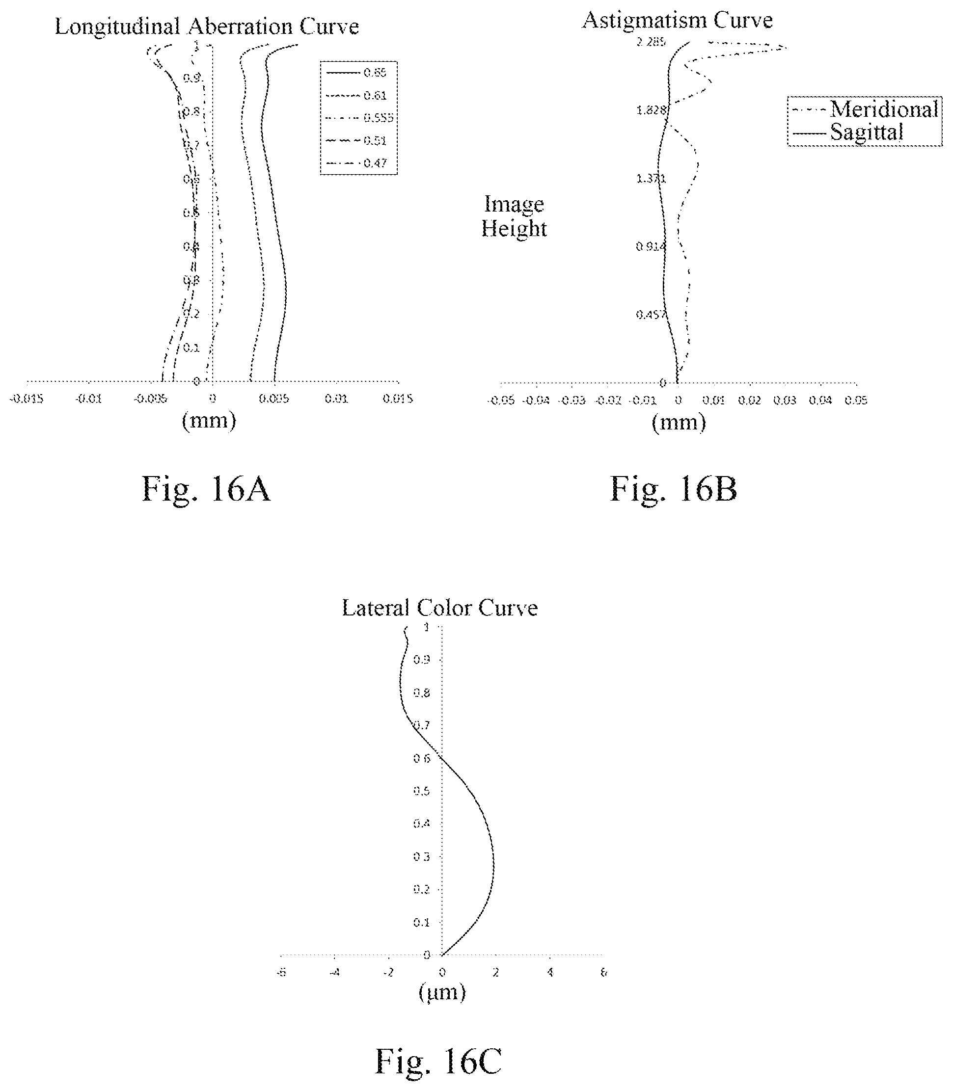
XML
uspto.report is an independent third-party trademark research tool that is not affiliated, endorsed, or sponsored by the United States Patent and Trademark Office (USPTO) or any other governmental organization. The information provided by uspto.report is based on publicly available data at the time of writing and is intended for informational purposes only.
While we strive to provide accurate and up-to-date information, we do not guarantee the accuracy, completeness, reliability, or suitability of the information displayed on this site. The use of this site is at your own risk. Any reliance you place on such information is therefore strictly at your own risk.
All official trademark data, including owner information, should be verified by visiting the official USPTO website at www.uspto.gov. This site is not intended to replace professional legal advice and should not be used as a substitute for consulting with a legal professional who is knowledgeable about trademark law.