Automated sandwich wrapping system
Berger , et al. Sep
U.S. patent number 10,759,557 [Application Number 15/219,651] was granted by the patent office on 2020-09-01 for automated sandwich wrapping system. This patent grant is currently assigned to Solbern Inc.. The grantee listed for this patent is Solbern Inc.. Invention is credited to Thomas G. Berger, George Stephens.


View All Diagrams
| United States Patent | 10,759,557 |
| Berger , et al. | September 1, 2020 |
Automated sandwich wrapping system
Abstract
An automated sandwich wrapping system is disclosed herein. In some embodiments, an automated sandwich wrapping system includes a folding subassembly having a plurality of folding plates to inwardly fold side portions of sandwich wrapping paper extending past ends of a sandwich, a roller subassembly having at least one roller to rotate the sandwich to wrap the sandwich, and a controller preprogrammed to control and coordinate operation of the folding subassembly and the roller subassembly. The folding plates move between an idle position and an active position.
| Inventors: | Berger; Thomas G. (Ridgefield, NJ), Stephens; George (Hewitt, NJ) | ||||||||||
|---|---|---|---|---|---|---|---|---|---|---|---|
| Applicant: |
|
||||||||||
| Assignee: | Solbern Inc. (Fairfield,
NJ) |
||||||||||
| Family ID: | 57994200 | ||||||||||
| Appl. No.: | 15/219,651 | ||||||||||
| Filed: | July 26, 2016 |
Prior Publication Data
| Document Identifier | Publication Date | |
|---|---|---|
| US 20170043888 A1 | Feb 16, 2017 | |
Related U.S. Patent Documents
| Application Number | Filing Date | Patent Number | Issue Date | ||
|---|---|---|---|---|---|
| 62204085 | Aug 12, 2015 | ||||
| Current U.S. Class: | 1/1 |
| Current CPC Class: | B65B 11/48 (20130101); B65B 25/16 (20130101); B65B 45/00 (20130101); B65B 11/004 (20130101); B65B 57/00 (20130101); B65B 67/10 (20130101) |
| Current International Class: | B65B 11/04 (20060101); B65B 57/00 (20060101); B65B 11/00 (20060101); B65B 45/00 (20060101); B65B 25/16 (20060101); B65B 11/48 (20060101); B65B 67/10 (20060101) |
| Field of Search: | ;53/209,210,211,214,216,218,206,203 ;493/426,429,431,405,416,422,427,434,442,454 |
References Cited [Referenced By]
U.S. Patent Documents
| 4608919 | September 1986 | Prows |
| 4913043 | April 1990 | Cheung |
| 5263407 | November 1993 | Pomara, Jr. |
| 6263789 | July 2001 | Karner |
| 2006/0144254 | July 2006 | Foulon, Jr. |
| 2013/0067858 | March 2013 | Spears |
Assistant Examiner: Hibbert-Copeland; Mary C
Attorney, Agent or Firm: McCarter & English, LLP
Parent Case Text
CROSS-REFERENCE TO RELATED APPLICATIONS
The present application claims the priority benefit of U.S. Provisional Application No. 62/204,085, filed Aug. 12, 2015, which is incorporated by reference in its entirety.
Claims
What is claimed is:
1. An automated sandwich wrapping system, comprising: a folding subassembly having a plurality of folding plates to inwardly fold side portions of sandwich wrapping paper extending past ends of a sandwich, the folding plates moving between an idle position and an active position; a left gripper and a right gripper configured to engage the ends of the sandwich to rotate and facilitate wrapping the sandwich; a roller subassembly having at least one roller to rotate the sandwich to wrap the sandwich; and a controller preprogrammed to control and coordinate operation of the folding subassembly and the roller subassembly.
2. The automated sandwich wrapping system of claim 1, wherein the folding subassembly comprises a left folding subassembly having a left upper folding plate and a right folding subassembly having a right upper folding plate to inwardly fold side portions of the sandwich wrapping paper extending past the ends of the sandwich, and wherein the folding subassembly comprises a left lower folding plate with the left gripper mounted thereto and a right lower folding plate with the right gripper mounted thereto, the left lower folding plate and right lower folding plate moving between an idle position and an active position to align and engage the left gripper and the right gripper with the ends of the sandwich.
3. The automated sandwich wrapping system of claim 1, wherein the folding subassembly comprises a left folding subassembly having a left folding plate and a right folding subassembly having a right folding plate to inwardly fold left and right side portions of the sandwich wrapping paper extending past the ends of the sandwich as the sandwich wrapping paper is being wrapped around the sandwich.
4. The automated sandwich wrapping system of claim 3, wherein the left folding plate includes a left opening and the right folding plate includes a right opening to receive the ends of the sandwich when the left folding plate and the right folding plate are in the active position.
5. The automated sandwich wrapping system of claim 4, further comprising a left sandwich guard extending from at least a portion of a perimeter of the left opening, and a right sandwich guard extending from at least a portion of a perimeter of the right opening, the left sandwich guard and the right sandwich guard facilitating wrapping at the ends of the sandwich by further folding the sandwich wrapping paper extending past the ends of the sandwich back over onto itself.
6. The automated sandwich wrapping system of claim 3, wherein the idle position includes the left folding plate coplanar with the right folding plate, and wherein the active position includes the left folding plate parallel with the right folding plate.
7. The automated sandwich wrapping system of claim 3, wherein the left folding subassembly comprises the left gripper having a rotatable plate to engage and rotate an end of the sandwich, and the right folding subassembly comprises the right gripper having a rotatable plate to engage and rotate an end of the sandwich.
8. The automated sandwich wrapping system of claim 3, comprising a sandwich wrapping paper support subassembly positioned between the left folding subassembly and the right folding subassembly to feed the sandwich wrapping paper during wrapping.
9. The automated sandwich wrapping system of claim 8, wherein the sandwich wrapping paper support subassembly comprises a folding panel having a left folding flap and a right folding flap to inwardly fold side portions of sandwich wrapping paper extending past ends of the sandwich onto itself prior to those portions being wrapped around the sandwich.
10. The automated sandwich wrapping system of claim 9, wherein the left folding subassembly includes a left plunger with a left extendable plunger arm and the right folding subassembly includes a right plunger with a right extendable plunger arm to fold the left folding flap and the right folding flap of the folding panel.
11. The automated sandwich wrapping system of claim 10, wherein the left extendable plunger arm moves the left folding flap from a perpendicular position partially folding the sandwich wrapping paper to a folded position thereby folding side portions of the sandwich wrapping paper back onto itself prior to those portions being wrapped around the sandwich, and wherein the right extendable plunger arm moves the right folding flap from a perpendicular position partially folding the sandwich wrapping paper to a folded position thereby folding side portions of the sandwich wrapping paper back onto itself prior to those portions being wrapped around the sandwich.
12. The automated sandwich wrapping system of claim 1, wherein the roller subassembly comprises a lower roller subassembly having a plurality of lower rollers and an upper roller subassembly having a plurality of upper rollers, the plurality of lower rollers and the plurality of upper rollers engaging the sandwich to rotate the sandwich to wrap the sandwich.
13. The automated sandwich wrapping system of claim 12, wherein the lower roller subassembly comprises a lower roller drive motor, the upper roller subassembly comprises an upper roller drive motor, and the lower roller drive motor and the upper roller drive motor are synchronized.
14. The automated sandwich wrapping system of claim 12, wherein the upper roller subassembly is pivotally attached to the lower roller subassembly to releasably secure the sandwich and sandwich wrapping paper therebetween.
15. The automated sandwich wrapping system of claim 1, comprising a creasing blade subassembly to crease sides of the sandwich wrapping paper extending past the ends of the sandwich, wherein the creasing blade subassembly creases the sandwich wrapping paper at approximately the ends of the sandwich.
16. An automated sandwich wrapping system, comprising: a sandwich wrapping paper support subassembly having a sandwich wrapping paper feeder plate to feed the sandwich wrapping paper during wrapping; a creasing blade subassembly having a left creasing blade and a right creasing blade to crease side portions of sandwich wrapping paper extending past ends of a sandwich; a left folding subassembly having a left lower folding plate and a left upper folding plate to inwardly fold left side portions of sandwich wrapping paper extending past a left end of the sandwich, the left folding subassembly positioned adjacent to a left side of the sandwich wrapping paper support subassembly; a right folding subassembly having a right lower folding plate and a right upper folding plate to inwardly fold right side portions of sandwich wrapping paper extending past a right end of the sandwich, the right folding subassembly positioned adjacent a right side of the sandwich wrapping paper support subassembly; a lower roller subassembly having a plurality of lower rollers to rotate the sandwich to wrap the sandwich; an upper roller subassembly pivotally attached to the lower roller subassembly, the upper roller subassembly having a plurality of upper rollers to rotate the sandwich to wrap the sandwich; and a controller preprogrammed to control and coordinate operation of the creasing blade subassembly, the left folding subassembly, the right folding subassembly, the lower roller subassembly, and the upper roller subassembly.
17. The automated sandwich wrapping system of claim 16, wherein the left folding subassembly comprises a left gripper mounted to the left lower folding plate, and wherein the right folding subassembly comprises a right gripper mounted to the right lower folding plate, the left gripper and the right gripper hingedly movable to engage ends of the sandwich to rotate the sandwich to wrap the sandwich.
18. The automated sandwich wrapping system of claim 16, wherein the left upper folding plate defines a left opening, and wherein the right upper folding plate defines a right opening to receive ends of the sandwich when the left folding plate and the right folding plate are in the active position.
19. The automated sandwich wrapping system of claim 16, comprising a folding panel, the folding panel having a left folding flap and a right folding flap to inwardly fold side portions of sandwich wrapping paper extending past ends of a sandwich onto itself prior to being wrapped around the sandwich.
20. An automated method of wrapping a sandwich, comprising: introducing a sandwich into an automated sandwich wrapping system, the automated sandwich wrapping system including (i) a folding subassembly having a plurality of folding plates, (ii) a left gripper, (iii) a right gripper, (iv) a roller subassembly having at least one roller, and v) a controller; controlling and coordinating operation of the folding subassembly, the left gripper, the right gripper, and the roller subassembly with the controller to: move one or more of the plurality of folding plates of the folding subassembly between an idle position and an active position to inwardly fold side portions of sandwich wrapping paper extending past ends of the sandwich; engage the ends of the sandwich with the left and right grippers and rotate the sandwich with the left and right grippers; and rotate the sandwich with the at least one roller of the roller subassembly to wrap the sandwich.
Description
FIELD OF THE DISCLOSURE
Embodiments of the present disclosure relate to wrapping systems and, more specifically, to an automated sandwich wrapping system.
BACKGROUND
Sandwiches (and other hand held food products) are often wrapped for transportation purposes, particularly for submarine sandwiches (e.g., sub, wedge, hoagie, hero, grinder, baguette, and the like). Wrapping can be an expensive and time intensive process, particularly for entities with high volumes of sandwich production (e.g., for manufacturers supplying large chain stores). Further, wrapping by hand can have inconsistent results and can also have associated health issues due to the repetitive motion required. Thus, a need exists for a system that wraps sandwiches more quickly than wrapping sandwiches solely by hand, among other things. These and/or other needs are addressed by embodiments of the automated sandwich wrapping system of the present disclosure.
SUMMARY
The present disclosure is directed to an automated sandwich wrapping system. Disclosed herein is an automated sandwich wrapping system including a folding subassembly having a plurality of folding plates to inwardly fold side portions of sandwich wrapping paper extending past ends of a sandwich, a roller subassembly to rotate the sandwich to wrap the sandwich, and a controller preprogrammed to control and coordinate operation of the folding subassembly and the roller subassembly.
Also disclosed herein is an automated sandwich wrapping system including a sandwich wrapping paper support subassembly to feed the sandwich wrapping paper during wrapping, a creasing blade subassembly to crease side portions of sandwich wrapping paper extending past ends of a sandwich, a left folding subassembly and a right folding subassembly to inwardly fold left side portions of sandwich wrapping paper extending past ends of the sandwich, a lower roller subassembly and an upper roller subassembly to rotate the sandwich to wrap the sandwich, and a controller. The controller is preprogrammed to control and coordinate operation of the creasing blade subassembly, the left folding subassembly, the right folding subassembly, the lower roller subassembly, and the upper roller subassembly. The lower roller subassembly and the upper roller subassembly have a plurality of rollers to rotate the sandwich to wrap the sandwich. The left folding subassembly is positioned adjacent to a left side of the sandwich wrapping paper support assembly, and the right folding subassembly is positioned adjacent a right side of the sandwich wrapping paper support assembly.
Also disclosed herein is an automated method of wrapping a sandwich including introducing the sandwich into an automated sandwich wrapping system, the automated sandwich wrapping system including a folding subassembly having a plurality of folding plates, a roller subassembly having at least one roller, and a controller. The method includes controlling and coordinating operation of the folding subassembly with the controller to move one or more of the plurality of folding plates of the folding subassembly between an idle position and an active position to inwardly fold side portions of sandwich wrapping paper extending past ends of the sandwich. The method includes controlling and coordinating operation of the roller subassembly with the controller to rotate the sandwich with the at least one roller of the roller subassembly to wrap the sandwich.
BRIEF DESCRIPTION OF THE DRAWINGS
The foregoing features of the invention will be apparent from the following Detailed Description, taken in connection with the accompanying drawings, in which:
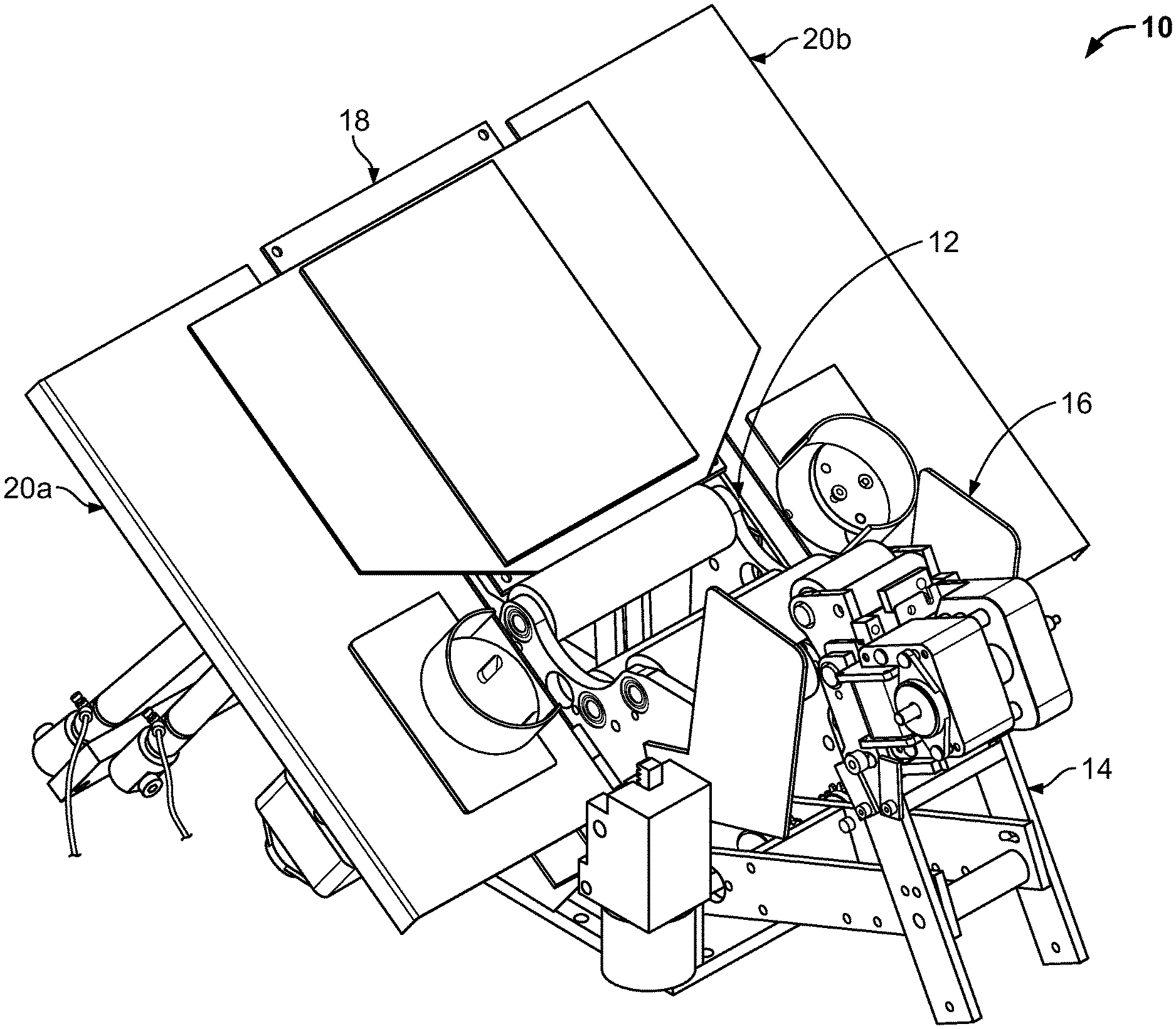
FIG. 1 is a front perspective view of an embodiment of an automated sandwich wrapping system having a lower roller subassembly, an upper roller subassembly pivotable from an open position to a closed position, a creasing blade subassembly rotatable from a front vertical position to a rear horizontal position, a sandwich wrapping paper support subassembly having a left folding flap and a right folding flap movable from a coplanar position to a perpendicular position to a folded position, a left folding subassembly, and a right folding subassembly, the left folding subassembly and right folding subassembly each have an upper folding plate movable from an idle position to an active position, a lower folding plate movable from an idle position to an active position, and an extendable plunger arm movable from a retracted position to an extended position;
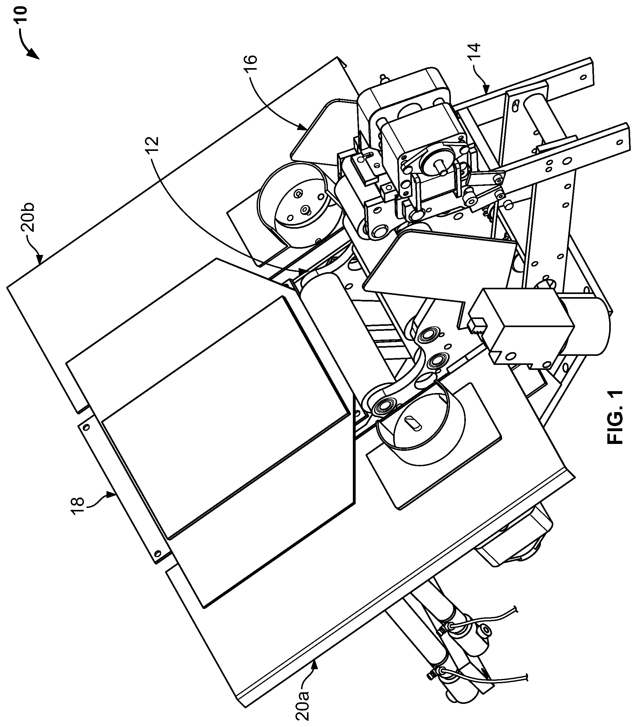
FIG. 2 is a rear perspective view of an embodiment of the automated sandwich wrapping system of FIG. 1;
FIG. 3 is a front perspective view of an embodiment of the lower roller subassembly and upper roller subassembly of the automated sandwich wrapping system of FIGS. 1-2;
FIG. 4 is a rear perspective view of an embodiment of the lower roller subassembly and upper roller subassembly of FIGS. 1-3;
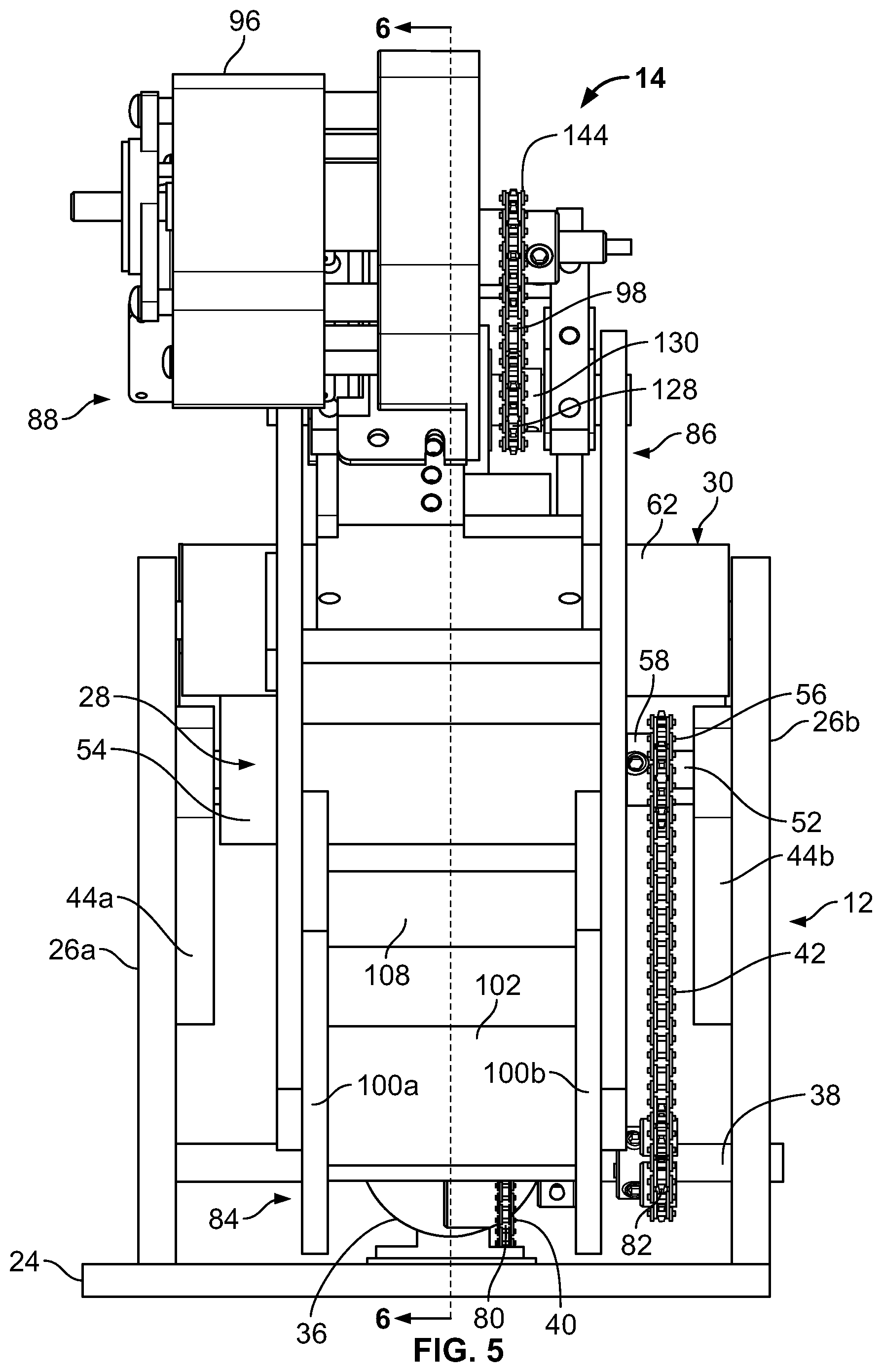
FIG. 5 is a front elevation view of an embodiment of the lower roller subassembly and upper roller subassembly of FIGS. 1-3;
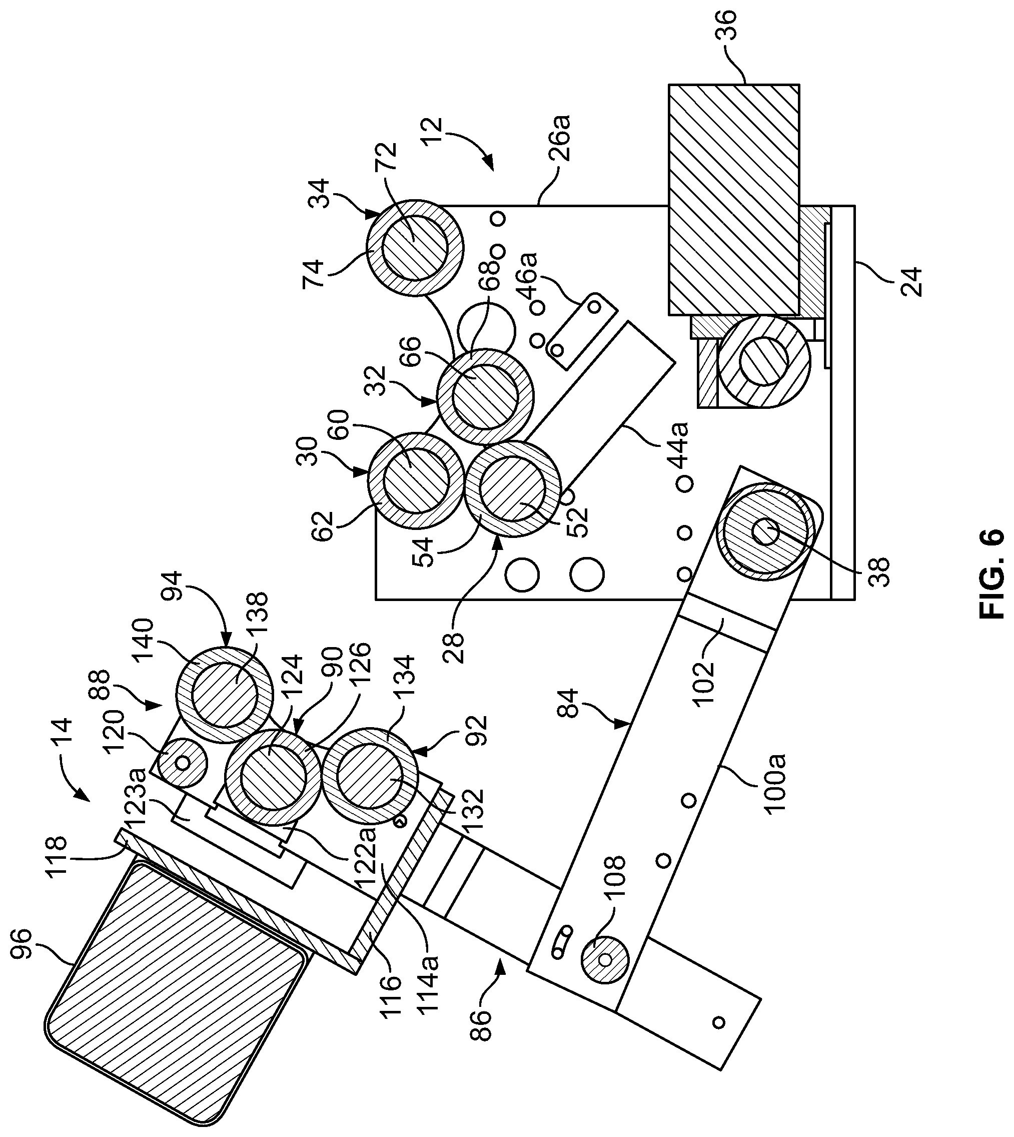
FIG. 6 is a sectional view of an embodiment of the lower roller subassembly and upper roller subassembly of FIG. 3 taken along section line 6-6 of FIG. 5;
FIG. 7 is a front perspective view of an embodiment of the creasing blade subassembly of the automated sandwich wrapping system of FIG. 1, additional components shown in dashed lines for the purpose of drawing clarity of the creasing blade subassembly;
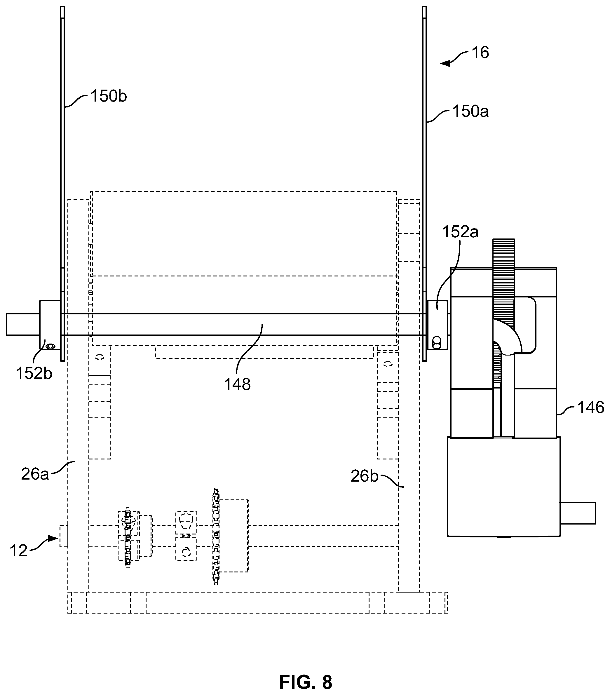
FIG. 8 is a rear elevational view of an embodiment of the creasing blade subassembly of FIGS. 1 and 7;
FIG. 9 is a side elevational view of an embodiment of the creasing blade subassembly of FIGS. 1 and 7-8;
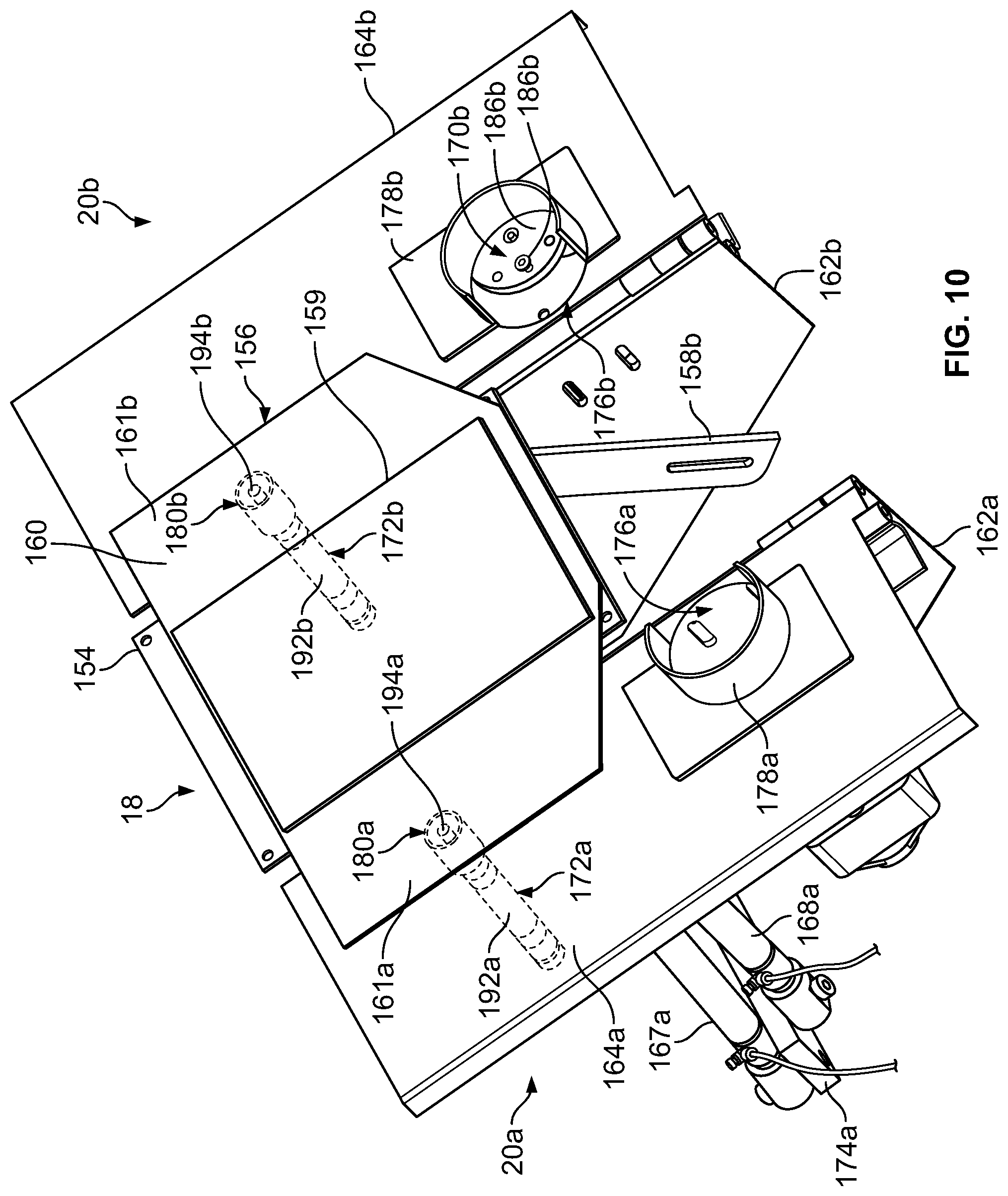
FIG. 10 is a front perspective view of an embodiment of the sandwich wrapping paper support subassembly, the left folding subassembly, and the right folding subassembly of the automated sandwich wrapping system of FIG. 1;
FIG. 11 is a rear perspective view of an embodiment of the sandwich wrapping paper support subassembly, the left folding subassembly, and the right folding subassembly of FIGS. 1 and 10;
FIG. 12 is a top plan view of an embodiment of the sandwich wrapping paper support subassembly, the left folding subassembly, and the right folding subassembly of FIGS. 1 and 10-11;
FIG. 13 is a bottom/front perspective view of an embodiment of the sandwich wrapping paper support subassembly, the left folding subassembly, and the right folding subassembly of FIGS. 1 and 10-12;
FIG. 14 is a front perspective view of an embodiment of the sandwich wrapping paper support subassembly, the left folding subassembly, and the right folding subassembly of FIGS. 1 and 10-14 when assembled with the lower roller subassembly, the upper roller subassembly, and the creasing blade subassembly;
FIG. 15 is a front perspective view of an embodiment of the automated sandwich wrapping system of FIG. 1 with the upper roller subassembly in the closed position, the creasing blade subassembly in the rear horizontal position, each of the left folding flap and the right folding flap in the coplanar position, each of the left upper folding plate and the right upper folding plate in the idle position, each of the left lower folding plate and the right lower folding plate in the idle position, and each of the left plunger and the right plunger in the retracted position;
FIG. 16 is a front perspective view of an embodiment of the automated sandwich wrapping system of FIGS. 1 and 15 with the upper roller subassembly in the closed position, the creasing blade subassembly in the front vertical position, each of the left folding flap and the right folding flap in the perpendicular position, each of the left upper folding plate and the right upper folding plate in the active position, each of the left lower folding plate and the right lower folding plate in the active position, and the left plunger and the right plunger in the retracted position;
FIG. 17 is a rear perspective view of an embodiment of the automated sandwich wrapping system of FIGS. 1 and 15-16 with the upper roller subassembly in the closed position, the creasing blade subassembly in the front vertical position, each of the left folding flap and the right folding flap in the folded position, each of the left upper folding plate and the right upper folding plate in the active position, each of the left lower folding plate and the right lower folding plate in the active position, and each of the left plunger and the right plunger in the extended position;
FIG. 18 is a top plan view of an embodiment of the automated sandwich wrapping system of FIGS. 1 and 17;
FIG. 19 is a front perspective view of an embodiment of the automated sandwich wrapping system of FIG. 1 in combination with a support structure, conveyer belt, label machine, wrapping paper roll, and wrapping paper cutting apparatus;
FIG. 20 is front perspective view of an embodiment of the automated sandwich wrapping system of FIGS. 1 and 19;
FIG. 21 is rear perspective view of an embodiment of the automated sandwich wrapping system of FIGS. 1 and 19-20; and
FIG. 22 is a side elevational view of an embodiment of the automated sandwich wrapping system of FIGS. 1 and 19-21.
DETAILED DESCRIPTION
It should be understood that the relative terminology used herein, such as "front", "rear", "left", "top", "bottom", "vertical", and "horizontal" is solely for the purposes of clarity and designation and is not intended to limit the invention to embodiments having a particular position and/or orientation. Accordingly, such relative terminology should not be construed to limit the scope of the present invention. In addition, it should be understood that the invention is not limited to embodiments having specific dimensions. Thus, any dimensions provided herein are merely for an exemplary purpose and are not intended to limit the invention to embodiments having particular dimensions.
Disclosed herein is an automated sandwich wrapping system. Although an automated sandwich wrapping system is described, the wrapping system can be used for other wrapping purposes aside from sandwiches (e.g., gift wrapping). The automated sandwich wrapping system can reduce the time for sandwich processing by automating sandwich wrapping and/or can reduce the resources needed to timely prepare sandwich orders. Additionally, the automated sandwich wrapping system can provide a consistent finished size and appearance, while also reducing potential health issues associated with repetitive motion for employees. Although the automated sandwich wrapping system is described specifically with respect to submarine sandwiches (e.g., sub, wedge, hoagie, hero, grinder, baguette, and the like), the automated sandwich wrapping system can be used with any type of sandwich or other food item.
FIGS. 1-2 are perspective views of an automated sandwich wrapping system 10. More specifically, FIG. 1 is a front perspective view of an embodiment of an automated sandwich wrapping system having a lower roller subassembly, an upper roller subassembly pivotable from an open position to a closed position, a creasing blade subassembly rotatable from a front vertical position to a rear horizontal position, a sandwich wrapping paper support subassembly having a left folding flap and a right folding flap movable from a coplanar position to a perpendicular position to a folded position, a left folding subassembly, and a right folding subassembly, the left folding subassembly and right folding subassembly each have an upper folding plate movable from an idle position to an active position, a lower folding plate movable from an idle position to an active position, and an extendable plunger arm movable from a retracted position to an extended position, and FIG. 2 is a rear perspective view of an embodiment of the automated sandwich wrapping system of FIG. 1.
The automated sandwich wrapping system 10 includes a lower roller subassembly 12, an upper roller subassembly 14, a creasing blade subassembly 16, a sandwich wrapping paper support subassembly 18, a left folding subassembly 20a, and a right folding subassembly 20b. The lower roller subassembly 12, the upper roller subassembly 14, the creasing blade subassembly 16, and the sandwich wrapping paper support subassembly 18 are positioned between the left folding subassembly 20a and the right folding subassembly 20b. The upper roller subassembly 14 is positioned towards a front of the automated sandwich wrapping system 10 and pivotally attached to the lower roller subassembly 12. The sandwich wrapping paper support subassembly 18 is positioned towards a rear of the automated sandwich wrapping system 10 and adjacent to the lower roller subassembly 12, such that the lower roller subassembly 12 is positioned between the upper roller subassembly 14 and the sandwich wrapping paper support assembly 18. The creasing blade subassembly 16 is pivotally interconnected with a front portion of the lower roller subassembly 12. One or more electronic controllers (e.g., local controller, remote controller, process controller, and the like) can be in electronic communication with components of the automated sandwich wrapping system 10 to control movement and operation thereof. More specifically, the electronic controller can control actuation of pistons, motors, and the like (as described herein) of the automated sandwich wrapping system 10 to control (e.g., induce movement of) and synchronize (e.g., coordinate) the movement (e.g., duration of movement, timing of movement, and the like) of one or more components of the lower roller subassembly 12, the upper roller subassembly 14, the creasing blade subassembly 16, the sandwich wrapping paper support subassembly 18, the left folding subassembly 20a, and/or the right folding subassembly 20b. Accordingly, the electronic controller can be preprogrammed for timed synchronization and/or at least partial automation of various components of the automated sandwich wrapping system 10.
FIGS. 3-6 are views of the lower roller subassembly 12 and upper roller subassembly 14 of the automated sandwich wrapping system 10. More specifically, FIG. 3 is a front perspective view of an embodiment of the lower roller subassembly and upper roller subassembly of the automated sandwich wrapping system of FIGS. 1-2, FIG. 4 is a rear perspective view of an embodiment of the lower roller subassembly and upper roller subassembly of FIGS. 1-3, FIG. 5 is a front elevation view of an embodiment of the lower roller subassembly and upper roller subassembly of FIGS. 1-3, and FIG. 6 is a sectional view of an embodiment of the lower roller subassembly and upper roller subassembly of FIG. 3 taken along section line 6-6 of FIG. 5. The upper roller subassembly 14 is pivotally connected to the lower roller subassembly 12. The upper roller subassembly 14 and lower roller subassembly 12 cooperate with one another to secure a sandwich between rollers thereof. At least one of the rollers of the upper roller subassembly 14 and lower roller subassembly 12 is driven by a motor so that the rollers of the upper roller subassembly 14 and lower roller subassembly 12 rotate together to roll the sandwich and sandwich wrapping paper, thereby wrapping the sandwich in the sandwich wrapping paper. A variety of motors can be used to drive the upper roller assembly 14 and/or the lower roller assembly 12, such as one or more stepper motors, one or more a gear motors, combinations thereof, or the like.
The lower roller subassembly 12 is provided with (e.g., includes) a base bottom wall 24, a base left sidewall 26a mounted to the base bottom wall 24, and a base right sidewall 26b mounted to the base bottom wall 24. As shown in FIG. 6, for example, the lower roller assembly 12 also includes a lower driver roller 28 (e.g., lower input roller), a first lower driven roller 30 (e.g., first lower output roller), a second lower driven roller 32 (e.g., second lower output roller), and a lower support roller 34. The lower roller assembly 12 further includes a lower roller drive motor 36, a compound train axle 38, a first lower roller drive chain 40, and a second lower roller drive chain 42 (e.g., as shown in FIG. 3).
As shown in FIG. 3, for example, the base left sidewall 26a is positioned towards a left side (e.g., first side), and attached to a top surface, of the base bottom wall 24. The base right sidewall 26b is positioned towards a right side (e.g., second side), and attached to a top surface, of the base bottom wall 24 opposite to the left side of the base bottom wall 24. In some embodiments, the base left sidewall 26a can define a left arc 49a in a top edge thereof. Similarly, the base right sidewall 26b can define a right arc 49b in a top edge thereof. The base left sidewall 26a (and the left arc 49a thereof) can be aligned with the base right sidewall 26b (and the right arc 49b thereof).
As shown in FIGS. 4 and 6, the base left sidewall 26a can include a left pressure arm 44a, a left pressure block 46a, one or more left roller openings 48a, and a left compound train axle opening 50a. The left pressure arm 44a and left pressure block 46a can be angularly mounted on an inside surface of the base left sidewall 26a (e.g., on the surface closer to the base right sidewall 26b). The left pressure arm 44a can be mounted adjacent to and below (e.g., closer to the base bottom wall 12 than) the left pressure block 46a. Further, the left pressure arm 44a can be mounted (e.g., spring mounted) to the base left sidewall 26a such that the left pressure arm 44a is biased to pivot up (e.g., away from the base bottom wall 12). More specifically, a first end of the left pressure arm 44b is pivotally mounted and a second end of the left pressure arm 44b rotates about the pivot point of the first end. Accordingly, the left pressure block 46a serves as a pivot limit for the left pressure arm 44a (e.g., a point by which the left pressure arm 44a cannot move beyond).
The one or more left roller openings 48a of the base left sidewall 26a can be positioned along the left arc 49a of the base left sidewall 26a. More specifically, a first and second left roller opening 48a can be adjacently positioned towards a front of the base left sidewall 26a, and a third left roller opening can be positioned towards a rear of the of the base left sidewall 26a, where all of the first, second, and third left roller openings 48a are positioned along the left arc 49a. The left compound train axle opening 50a can be disposed towards a front lower portion of the base left sidewall 26a (e.g., lower than the one or more left roller openings 48a).
Similarly, as shown in FIG. 4, for example, the base right sidewall 26b can include a right pressure arm 44b, a right pressure block 46b, one or more right roller openings 48b, and a right compound train axle opening 50b. The right pressure arm 44b and right pressure block 46b (not shown) can be angularly mounted on an inside surface of the base right sidewall 26b (e.g., on the surface closer to the base left sidewall 26a). The right pressure arm 44b can be mounted adjacent to and below (e.g., closer to the base bottom wall 12 than) the right pressure block 46b. Further, the right pressure arm 44b (e.g., as shown in FIG. 5) can be mounted (e.g., spring mounted) to the base right sidewall 26b such that the right pressure arm 44b is biased to pivot up (e.g., away from the base bottom wall 12). More specifically, a first end of the right pressure arm 44b is pivotally mounted and a second end of the right pressure arm 44b rotates about the pivot point of the first end. Accordingly, the right pressure block 46b serves as a pivot limit for the right pressure arm 44b (e.g., a point by which the right pressure arm 44b cannot move beyond).
The one or more right roller openings 48b of the base right sidewall 26b can be positioned along the right arc 49b of the base left sidewall 26b. More specifically, a first and second left roller opening 48b can be adjacently positioned towards a front of the base right sidewall 26b, and a third right roller opening can be positioned towards a rear of the of the base right sidewall 26b, where all of the first, second, and third right roller openings 48b are positioned along the right arc 49b. The right compound train axle opening 50b can be disposed towards a front lower portion of the base right sidewall 26b (e.g., lower than the one or more right roller openings 48b).
One or more features of the base left sidewall 26a and the base right sidewall 26b described above can be horizontally aligned (e.g., mirrored) with one another. More specifically, the left pressure arm 44a can be aligned with the right pressure arm 44b, the left pressure block 46a can be aligned with the right pressure block 46b, the one or more left roller openings 48a can be aligned with the one or more right roller openings 48b, and the left compound train axle opening 50a can be aligned with the right compound train axle opening 50b.
As shown in FIG. 6, for example, the lower driver roller 28 can include a lower driver roller axle 52, a lower driver roller covering 54 positioned about the lower driver roller axle 52, a lower driver roller sprocket 56 positioned about and fixedly attached (e.g., by a set screw and/or collar) to the lower driver roller axle 52, and lower driver roller mounting components 58. The lower driver roller covering 54 does not cover the entire length of the lower driver roller axle 52, and more specifically, the lower driver roller covering 54 does not cover the portion of the lower driver roller axle 52 where the lower driver roller sprocket 56 is attached. The lower driver roller sprocket 56 can be fixedly attached towards a right side of the lower driver roller axle 52. A left end (e.g., a first end) of the lower driver roller 28 can be rotatably mounted (by lower driver roller mounting components 58) to a second end of the left pressure arm 44a of the base left sidewall 26a, and a right end (e.g., a second end) of the lower driver roller 28 can be rotatably mounted (by lower driver roller mounting components 58) to the second end of the right pressure arm 44b of the base right sidewall 26b. Accordingly, the lower driver roller 28 pivots along with the second ends of the left pressure arm 44a and the right pivot arm 44b and is biased upwardly (e.g., and rearwardly) by the left pressure arm 44a and right pressure arm 44b. The lower driver roller mounting components 58 can include ball bearings, nuts, washers, screws, and the like.
The first lower driven roller 30 can include a first lower driven roller axle 60, a first lower driven roller covering 62 positioned about the first lower driver roller axle 60, and first lower driven roller mounting components 64. The first lower driver roller covering 54 can cover substantially the entire length of the first lower driven roller axle 52. A left end (e.g., a first end) of the first lower driven roller 30 can be rotatably mounted (by first lower driven roller mounting components 64) to one of the left roller opening 48a of the base left sidewall 26a, and a right end (e.g., a second end) of the first lower driven roller 30 can be rotatably mounted (by first lower driven roller mounting components 64) to one of the right roller openings 48b of the base right sidewall 26b. The first lower driven roller mounting components 64 can include ball bearings, nuts, washers, screws, and the like.
The second lower driven roller 32 can include a second lower driven roller axle 66, a second lower driven roller covering 68 positioned about the second lower driver roller axle 66, and second lower driven roller mounting components 70. The second lower driver roller covering 68 can cover substantially the entire length of the second lower driven roller axle 66. A left end (e.g., a first end) of the second lower driven roller 32 can be rotatably mounted (by second lower driven roller mounting components 70) to one of the left roller opening 48a of the base left sidewall 26a, and a right end (e.g., a second end) of the second lower driven roller 32 can be rotatably mounted (by second lower driven roller mounting components 70) to one of the right roller openings 48b of the base right sidewall 26b. The second lower driven roller mounting components 70 can include ball bearings, nuts, washers, screws, and the like.
The lower support roller 34 can include a lower support roller axle 72, a lower support roller covering 74 positioned about the lower support roller axle 72, and lower support roller mounting components 76. The lower support roller covering 74 can cover substantially the entire length of the lower support roller axle 72. A left end (e.g., a first end) of the lower support roller 34 can be rotatably mounted (by lower support roller mounting components 76) to one of the left roller opening 48a of the base left sidewall 26a, and a right end (e.g., a second end) of the lower support roller 32 can be rotatably mounted (by lower support roller mounting components 76) to one of the right roller openings 48b of the base right sidewall 26b. The lower support roller mounting components 76 can include ball bearings, nuts, washers, screws, and the like.
Accordingly, the first lower driven roller 30, the second lower driven roller 32, and the lower support roller 34 are positioned about the left arc of the base left sidewall 26a and the right arc of the base right sidewall 26b. More specifically, the first lower driven roller 30 is positioned at a front end of the lower roller subassembly 12 approximately at a front end of the left arc 49a and right arc 49b, the lower support roller 34 is positioned at a rear end of the lower roller subassembly 12 opposite the first lower driven roller 30 approximately at a rear end of the left arc 49a and right arc 49b, and the second lower driven roller 32 is positioned between, and lower than, the first lower driven roller 30 and the lower support roller 34 (e.g., at a lower point of the left arc 49a and the right arc 49b). Further, the lower drive roller 28 is biased upwardly (e.g., and rearwardly) to make and maintain contact with at least one of the first lower driven roller 30 and/or the second lower driven roller 32, where the first lower driven roller 30 and the second lower driven roller 32 do not make contact with each other. As a result, rotation of the lower drive roller 28 drives rotation of both the first lower driven roller 30 and/or the second lower driven roller 32 in a direction opposite to that of the lower drive roller 28. The lower drive roller 28, first lower driven roller 30, and/or the second lower driven roller 32 have the same surface speed (as a result of direct contact), and have the same rotational speed if the lower drive roller 28, first lower driven roller 30, and/or the second lower driven roller 32 are the same size (e.g., have the same diameter as one another).
The lower roller drive motor 36 can be mounted to the base bottom wall 24 and at least partially positioned between the base left sidewall 26a and the base right sidewall 26b. The lower roller drive motor 36 includes a lower roller drive motor sprocket 78 which provides rotational output of the lower roller drive motor 36.
The compound train axle 38 (e.g., as shown in FIG. 5) is mounted to base left sidewall 26a and the base right sidewall 26b. More specifically, a left end (e.g., first end) of the compound train axle 38 is rotatably mounted to the left compound train axle opening 50a (e.g., by compound train axle mounting components 83) and a right end (e.g., second end) of the compound train axle 38 is rotatably mounted to the right compound train axle opening (e.g., by compound train axle mounting components 83). The compound train axle mounting components 83 can include ball bearings, nuts, washers, screws, and the like.
The compound train axle 38 includes a first intermediate sprocket 80 and a second intermediate sprocket 82, each fixedly attached to the compound train axle 38 (e.g., by a set screw and/or collar). The first intermediate sprocket 80 is aligned with the lower roller drive motor sprocket 78 of the lower roller drive motor 36, and the second intermediate sprocket 82 is aligned with the lower driver roller sprocket 56. Accordingly, the second intermediate sprocket 82 is disposed towards the right side of the compound train axle 38. The first lower roller drive chain 40 mechanically connects the lower roller drive motor sprocket 78 with the first intermediate sprocket 80. The second lower roller drive chain 42 mechanically connects the second intermediate sprocket 82 with the lower drive roller sprocket 56. The sizes of one or more of the lower driver roller sprocket 56, the lower roller drive motor sprocket 78, the first intermediate sprocket 80, and/or the second intermediate sprocket 82 can be varied to alter the performance of the gear train (e.g., the speed ratio, mechanical advantage, and the like.).
Accordingly, mechanical power is transferred through the gear train from the lower roller drive motor 36 to the lower roller drive motor sprocket 78 to the first lower roller drive chain 40 to the first intermediate sprocket 80 to the compound train axle 38 to the second intermediate sprocket 82 to the second lower roller drive chain 42 to the lower driver roller sprocket 56 to the lower driver roller 28 to both the first lower driven roller 30 and the second lower driven roller 32. Thereby, the lower roller drive motor 36 provides rotational power and energy to the first lower driven roller 30 and second lower driven roller 32. The resulting speed of the first lower driven roller 30 and second lower driven roller 32 being dependent upon the power output of the lower roller drive motor 36 and the gear train characteristics (e.g., sizes of sprockets, sizes of rollers, and the like).
As shown in FIG. 6, for example, the upper roller subassembly 14 is pivotably connected to the lower roller subassembly 12 and cooperates therewith. The upper roller subassembly 14 pivots between an open position and a closed position. When the upper roller subassembly 14 is in an open position, a sandwich and sandwich wrapping paper can be positioned on the lower roller subassembly 12 (prior to rolling) or removed from the lower roller subassembly 12 (after the sandwich wrapping paper has been wrapped around the sandwich). When the upper roller subassembly 14 is in the closed position, the sandwich and sandwich wrapping paper are secured between the upper roller subassembly 14 and the lower subassembly 12. Once a sandwich and sandwich wrapping paper is secured between the upper roller subassembly 14 and the lower roller subassembly 12, the rollers of the upper roller subassembly 14 and/or lower roller subassembly 12 rotate (as driven by one or more motors) to wrap the sandwich in the sandwich wrapping paper.
The upper roller subassembly 14 includes a lower vertical arm 84, an upper horizontal arm 86, an upper roller mount 88, an upper driver roller 90 (e.g., upper input roller), a first upper driven roller 92 (e.g., first upper output roller), a second upper driven roller 94 (e.g., second upper output roller 94), an upper roller drive motor 96, and an upper roller drive chain 98.
As shown in FIGS. 3-4, for example, the lower vertical arm 84 includes a lower vertical arm left sidewall 100a, a lower vertical arm right sidewall 100b aligned with the lower vertical arm left sidewall, one or more lower vertical arm support struts 102 therebetween, and one or more lower vertical arm mounting components 104. The lower vertical arm support struts 102 facilitate structural stability of the lower vertical arm 84. The lower vertical arm 84 is rotatably mounted to the compound train axle 38 by the one or more lower vertical arm mounting components 104 (e.g., ball bearings, nuts, washers, screws, and the like). As a result, rotation of the compound train axle 38 is independent of movement of the vertical arm 84 of the upper roller subassembly 14.
The upper horizontal arm 86 includes an upper horizontal arm left sidewall 106a, an upper horizontal arm right sidewall 106b aligned with the upper horizontal arm left sidewall, and one or more upper horizontal arm support struts 108 therebetween (e.g., where one or more of the support struts can be positioned between the lower vertical arm left sidewall 100a and lower vertical arm right sidewall 100b and also positioned between the upper horizontal arm left sidewall 106a and upper horizontal arm right sidewall 106b). The upper horizontal arm support struts 108 facilitate structural stability of the lower vertical arm 84. The first end of the upper horizontal arm 86 can be fixedly attached to the lower vertical arm 84. For example, mounting components (e.g., nuts, bolts, screws, and the like) can be inserted through one or more holes in the upper horizontal arm 86 and/or the lower vertical arm 84. The upper horizontal arm left sidewall 106a includes a left limiter slot 110a and upper horizontal arm right sidewall 106b includes a right limiter slot 110b. The left limiter slot 110a and right limiter slot 110b are aligned with one another and can be arc-shaped.
A left upper limiter panel 111a and a left lower limiter panel 112a can each be rotatably attached to the upper horizontal arm left sidewall 106a. More specifically, a first end of the left upper limiter panel 111a can be pivotally attached to the upper horizontal arm left sidewall 106a such that a second end of the left upper limiter panel 111a can be rotatably positioned to cover at least a portion of the upper portion of the left limiter slot 110a. Similarly, a first end of the left lower limiter panel 112a can be pivotally attached to the upper horizontal arm left sidewall 106a such that a second end of the left lower limiter panel 112a can be rotatably positioned to cover at least a portion of the lower portion of the left limiter slot 110a.
A right upper limiter panel 111b and a right lower limiter panel 112b can each be rotatably attached to the upper horizontal arm right sidewall 106b. More specifically, a first end of the right upper limiter panel 111b can be pivotally attached to the upper horizontal arm right sidewall 106b such that a second end of the right upper limiter panel 111b can be rotatably positioned to cover at least a portion of the upper portion of the right limiter slot 110b. Similarly, a first end of the right lower limiter panel 112b can be pivotally attached to the upper horizontal arm right sidewall 106b such that a second end of the right lower limiter panel 112b can be rotatably positioned to cover at least a portion of the lower portion of the right limiter slot 110b.
The upper roller mount 88 can include an upper roller mount left sidewall 114a, an upper roller mount right sidewall 114b, an upper roller mount back wall 116, an upper roller mount top wall 118, one or more upper roller mount support struts 120, one or more bearing blocks 122, and one or more tension mounts 123. More specifically, the upper roller mount left sidewall 114a is aligned with the upper roller mount right sidewall 114b with the one or more upper roller mount support struts 120 therebetween. The upper roller mount front wall 116 can be attached at front edges of the upper roller mount left sidewall 114a and upper roller mount right sidewall 114b. The upper roller mount top wall 118 can be attached to the upper roller mount front wall 116, the top edge of the upper roller mount left sidewall 114a, and/or the top edge the upper roller mount right sidewall 114b. The one or more upper roller mount support struts 120 can be positioned between the upper roller mount left sidewall 114a and the upper roller mount right sidewall 114b, such as at an upper portion thereof (e.g., at the rearward end thereof). The one or more upper roller mount support struts 120 provide structural stability for the upper roller mount 88.
A left bearing block 122a can be positioned in a middle portion of the upper roller mount left sidewall 114a and a right bearing block 122b can be positioned in a middle portion of the upper roller mount right sidewall 114b. The one or more tension mounts 123 can be positioned above each of the one or more bearing blocks 122. More specifically, a left tension mount 123a is attached (e.g., via one or more bolts) to an upper edge of the upper roller mount left sidewall 114a and a right tension mount 123b is attached (e.g., via one or more bolts) to an upper edge of the upper roller mount rights sidewall 114b. The left tension mount 123a is also attached to the left bearing block 122a (e.g., via one or more bolts), such that the adjustable attachment (e.g., bolt) is in compression (the degree of which can be adjustable). The right tension mount 123b is also attached to the right bearing block 122b (e.g., via one or more bolts), such that the adjustable attachment (e.g., bolt) is in compression (the degree of which can be adjustable).
The upper roller mount 88 can be rotatably mounted to the upper horizontal arm 86 using one or more mounting components (e.g., tensioner, bearing block, bearing, nuts, bolts, screws, and the like). The upper roller mount 88 can include a left limiter bolt 115a fixedly attached to the upper roller mount left sidewall 114a and contained within and protruding out of the left limiter slot 106a. The upper roller mount 88 can include a right limiter bolt 115b fixedly attached to the upper roller mount right sidewall 114b and contained within and protruding out of the right limiter slot 106b. As a result, rotation of the upper roller mount 88 relative to the upper horizontal arm 86 can be controlled (e.g., limited) by motion of the left limiter bolt 115a within the left limiter slot 110a and motion of the right limiter bolt 115b within the right limiter slot 110b. Further, the position of the left upper limiter panel 111a, left lower limiter panel 112a, right upper limiter panel 111b, and/or right lower limiter panel 112b can be adjusted to control the degree of rotation of the upper roller mount 88 relative to the upper horizontal arm 86.
The upper driver roller 90 (e.g., upper input roller) can include an upper driver roller axle 124, an upper driver roller covering 126 positioned about the upper driver roller axle 124, an upper driver roller sprocket 128 positioned about and fixedly attached (e.g., by a set screw and/or collar) to the upper driver roller axle 124, and upper driver roller mounting components 130. The upper driver roller covering 126 does not cover the entire length of the upper driver roller axle 124, and more specifically, the upper driver roller covering 126 does not cover the portion of the upper driver roller axle 124 where the upper driver roller sprocket 128 is attached. The upper driver roller sprocket 128 can be fixedly attached towards a right side of the upper driver roller axle 124.
A left end (e.g., a first end) of the upper driver roller 90 can be rotatably mounted (by upper driver roller mounting components 130) to the left bearing block 122a in the middle portion of the upper roller mount left sidewall 114a and a right end (e.g., a second end) of the upper driver roller 90 can be rotatably mounted (e.g., by upper driver roller mounting components 130) to the right bearing block 122b in the middle portion of the upper roller mount right sidewall 114b. Accordingly, the upper driver roller 90 is biased downwardly relative to the upper roller mount 88 due to the bearing blocks 122 and tension mounts 123. The upper driver roller mounting components 130 can include ball bearings, nuts, washers, screws, and the like.
The first upper driven roller 92 (e.g., first upper output roller) can include a first upper driven roller axle 132, an upper driven roller covering 134 positioned about the upper driven roller axle 132, and first upper driver roller mounting components 136. The upper driver roller covering 134 can cover substantially the entire length of the first upper driven roller axle 132. A left end (e.g., a first end) of the first upper driven roller 92 can be rotatably mounted (by upper driven roller mounting components 136) to a lower front portion of the upper roller mount left sidewall 114a and a right end (e.g., a second end) of the first upper driven roller 92 can be rotatably mounted (by upper driven roller mounting components 136) to a lower front portion of the upper roller mount right sidewall 114b. The upper driven roller mounting components 136 can include ball bearings, nuts, washers, screws, and the like.
The second upper driven roller 94 (e.g., second upper output roller) can include a second upper driven roller axle 138, an upper driven roller covering 140 positioned about the upper driven roller axle 138, and second upper driven roller mounting components 142. The upper driver roller covering 134 can cover substantially the entire length of the second upper driven roller axle 132. A left end (e.g., a first end) of the second upper driven roller 94 can be rotatably mounted (by upper driven roller mounting components 142) to a lower rear portion of the upper roller mount left sidewall 114a and a right end (e.g., a second end) of the second upper driven roller 94 can be rotatably mounted (by upper driven roller mounting components 136) to a lower rear portion of the upper roller mount right sidewall 114b. The upper driven roller mounting components 142 can include ball bearings, nuts, washers, screws, and the like.
Accordingly, as shown in FIG. 6, for example, the upper driver roller 90 is positioned above and in between the first upper driven roller 92 and the second upper driven roller 94. Further, because the upper driver roller 90 is biased downwardly relative to the upper roller mount 88, the upper driver roller 90 is biased to make and maintain contact with at least one of the first upper driven roller 92 and the second upper driven roller 94. As a result, rotation of the upper driver roller 90 drives rotation of both the first upper driven roller 92 and the second upper driven roller 94 at a speed the same as, but in a direction opposite to that of, the upper driver roller 90.
As shown in FIG. 5, for example, the upper roller subassembly 14 is narrower than the lower roller subassembly 12. More specifically, the first upper driven roller 92 and the second upper driven roller 94 of the upper roller subassembly 14 are narrower than the first lower driven roller 30, the second lower driven roller 32, and/or the lower support roller 34 of the lower roller subassembly 12. This is designed to provide sufficient space for the left sandwich guard and right sandwich guard described below.
The upper roller drive motor 96 can be mounted to the upper roller mount top wall 118 and includes an upper roller drive motor sprocket 144 which provides rotational output of the upper roller drive motor 96. The upper roller drive motor sprocket 144 is aligned with the upper driver roller sprocket 128. The upper roller drive chain 98 mechanically connects the upper driver roller sprocket 128 and the upper roller drive motor sprocket 144. The sizes of one or more of the upper driver roller sprocket 128 and the upper roller drive motor sprocket 144 can be varied to alter the performance of the gear train (e.g., the speed ratio, mechanical advantage, and the like).
Accordingly, mechanical power is transferred through the gear train from the upper roller drive motor 96 to the upper roller drive motor sprocket 144 to the upper roller drive chain 98 to the upper driver roller sprocket 128 to the first upper driver roller 90 to both the first upper driven roller 92 and the second upper driven roller 94. Thereby, the upper roller drive motor 96 provides rotational power and energy to the first upper driven roller 92 and second upper driven roller 94 via the lower driver roller 28. The resulting speed of the upper driver roller 90 being dependent upon the power output of the upper roller drive motor 96 and the gear train characteristics (e.g., sizes of sprockets, sizes of rollers, and the like).
The upper roller subassembly 14 pivots from an open position (e.g., as shown in FIGS. 3-6) where the upper roller mount 114a (and associated upper driver roller 90, first upper driven roller 92, and second upper driven roller 94) is pivoted away from the top portion of the lower roller subassembly 12 (and associated the lower driver roller 28, first lower driven roller 30, second lower driven roller 32, and lower support roller 34) to a closed position where the upper roller mount 114a is pivoted towards the top portion of the lower roller subassembly 12. In the closed position the first upper driven roller 92, second upper driven roller 94, first lower driven roller 30, second lower driven roller 32, and lower support roller 34 form a generally circular shape to rotate and wrap a sandwich placed therein.
The multiple drive motors and rollers facilitate even pressure on wrapping the sandwich. The lower roller drive motor 36 and upper roller drive motor 96 can be synchronized in the sense that the first lower driven roller 30, second lower driven roller 32, first upper driven roller 92, and second upper driven roller 94 are all providing the same surface speed on the sandwich. Although multiple drive motors and rollers are disclosed herein, the automated sandwich wrapping system 10 can use more or fewer drive motors and/or rollers. For example, the automated sandwich wrapping system 10 can utilize only the first upper driven roller 92, second upper driven roller 94, the lower driver roller 28, first lower driven roller 30, lower support roller 34, and lower roller drive motor 36 (thereby omitting the second lower driven roller 32, the upper driver roller 90, and upper roller drive motor 96).
FIGS. 7-9 are view of the creasing blade subassembly of the automated sandwich wrapping system. More specifically, FIG. 7 is a front perspective view of an embodiment of the creasing blade subassembly of the automated sandwich wrapping system of FIG. 1, additional components shown in dashed lines for the purpose of drawing clarity of the creasing blade subassembly, FIG. 8 is a rear elevational view of an embodiment of the creasing blade subassembly of FIGS. 1 and 7, and FIG. 9 is a side elevational view of an embodiment of the creasing blade subassembly of FIGS. 1 and 7-8. The creasing blade subassembly 16 creases the sandwich wrapping paper extending past ends of the sandwich to make it easier to fold the sandwich wrapping paper, which facilitates tight wrapping of the sandwich.
The creasing blade subassembly 16 includes a creasing blade drive motor 146, a creasing blade axle 148, a left creasing blade 150a, right creasing blade 150b, left creasing blade mounting components 152a, and right creasing blade mounting components 152b. More specifically, the creasing blade drive motor 146 is in direct mechanical communication with the creasing blade axle 148. The creasing blade drive motor 146 can be a gear rack motor, a stepper motor, or any other suitable type of motor.
The creasing blade axle 148 is rotatably mounted to lower roller subassembly 12. More specifically, a first end of the creasing blade axle 148 is rotatably mounted to and extends through the base left sidewall 26a and a second end of the creasing blade axle 148 is rotatably mounted to and extends through the base right sidewall 26b. Left creasing blade 150a is fixedly attached (by left creasing blade mounting components 152a) approximately at first end of the creasing blade axle 148 adjacent to the outside surface of the base left sidewall 26a) and right creasing blade 150b is fixedly attached (by right creasing blade mounting components 152b) approximately at second end of the creasing blade axle 148 adjacent to the outside surface of the base right sidewall 26b). The left creasing blade mounting components 152a and the right creasing blade mounting components 152b can include collars, nuts, washers, screws, and the like.
Accordingly, when the creasing blade drive motor 146 rotates the creasing blade axle 148 both the left creasing blade 150a and the right creasing blade 150b rotate together with the creasing blade axle 148. The left creasing blade 150 and right creasing blade 150b rotate from a front vertical position (as shown in FIGS. 7-9) to a rear horizontal position in which at least a portion of the left creasing blade 150a rotates past the left arc 49a of the base left sidewall 26a and in which at least a portion of the right creasing blade 150b rotates past the right arc 49b of the base right sidewall 26b.
FIGS. 10-14 are views of the sandwich wrapping paper support subassembly, the left folding subassembly, and the right folding subassembly of the automated sandwich wrapping system. More specifically, FIG. 10 is a front perspective view of an embodiment of the sandwich wrapping paper support subassembly, the left folding subassembly, and the right folding subassembly of the automated sandwich wrapping system of FIG. 1, FIG. 11 is a rear perspective view of an embodiment of the sandwich wrapping paper support subassembly, the left folding subassembly, and the right folding subassembly of FIGS. 1 and 10, FIG. 12 is a top plan view of an embodiment of the sandwich wrapping paper support subassembly, the left folding subassembly, and the right folding subassembly of FIGS. 1 and 10-11, FIG. 13 is a bottom plan view of an embodiment of the sandwich wrapping paper support subassembly, the left folding subassembly, and the right folding subassembly of FIGS. 1 and 10-12, and FIG. 14 is a front perspective view of an embodiment of the sandwich wrapping paper support subassembly, the left folding subassembly, and the right folding subassembly of FIGS. 1 and 10-14 when assembled with the lower roller subassembly, the upper roller subassembly, and the creasing blade subassembly.
The sandwich wrapping paper support assembly 18 supports and secures sandwich wrapping paper to facilitate proper feeding of the sandwich wrapping paper to ensure proper wrapping of the sandwich. The sandwich wrapping paper support assembly 18 also folds portions of the sandwich wrapping paper to facilitate wrapping of the sandwich. The sandwich wrapping paper support assembly 18 is positioned in between a left folding subassembly 20a and a right folding subassembly 20b. The sandwich wrapping paper support subassembly 18 includes a sandwich wrapping paper feeder plate 154, a folding panel 156, a left sandwich wrapping paper feeder plate mount 158a, a right sandwich wrapping paper feeder plate mount 158b, a sandwich wrapping paper stabilizing clip 159.
As shown in FIGS. 11 and 13, for example, a first end of the left sandwich wrapping paper feeder plate mount 158a is pivotably attached at a bottom surface approximately at a left side of the sandwich wrapping paper feeder plate 154. A second end of the left sandwich wrapping paper feeder plate mount 158a is pivotally and/or slidably attached to a left sidewall 162a of the left folding subassembly 20a (discussed below). A first end of the right sandwich wrapping paper feeder plate mount 158b is pivotably attached at a bottom surface approximately at a right side of the sandwich wrapping paper feeder plate 154. A second end of the right sandwich wrapping paper feeder plate mount 158b is pivotally and/or slidably attached to a right sidewall 162b of the right folding subassembly 20b (discussed below). The left sandwich wrapping paper feeder plate mount 158a and the right sandwich wrapping paper feeder plate mount 158b allow the sandwich wrapping paper feeder plate 154 to be oriented at a variety of angles and/or heights.
As shown in FIGS. 10, 12, and 14, for example, the folding panel 156 includes a body portion 160, a left folding flap 161a, and a right folding flap 161b. The bottom edge of the left folding flap 161a and the bottom edge of the right folding flap 161b can be tapered. The left folding flap 161a extends past the left edge of the sandwich wrapping paper feeder plate 154 such that the left folding flap 161a is foldable at approximately the left edge of the sandwich wrapping paper feeder plate 154. The right folding flap 161b extends past the right edge of the sandwich wrapping paper feeder plate 154 such that the right folding flap 161b is foldable at approximately the right edge of the sandwich wrapping paper feeder plate 154. As described in more detail below, the left folding flap 161a and the right folding flap 161b can pivotally move into one or more positions or positions (described below).
The sandwich wrapping paper stabilizing clip 159 is mounted approximately at a rear edge of the sandwich wrapping paper feeder plate 154, and is mounted on top of the folding panel 156 such that the folding panel 156 is positioned between the sandwich wrapping paper feeder plate 154 and the sandwich wrapping paper stabilizing clip 159. The sandwich wrapping paper stabilizing clip 159 can be attached to the sandwich wrapping paper feeder plate 154 and/or the folding panel 156 using mounting components (e.g., clamps, nuts, bolts, screws, and the like).
The left folding subassembly 20a includes a left sidewall 162a, a left upper folding plate 164a, a left lower folding plate 166a, a left upper folding plate piston 167a, a left lower folding plate piston 168a, a left gripper 170a, and a left plunger 172a. More specifically, the left sidewall 162a includes a left support brace 174a extending outwardly from a left surface at approximately a bottom edge of the left sidewall 162a (e.g., away from the sandwich wrapping paper support subassembly 18). The left support brace 174a provides, among other things, stability for the left folding subassembly 20a.
As shown in FIGS. 11 and 13, for example, the left upper folding plate 164a and right upper folding plate 164b hingedly move between an idle position to an active position to fold ends of the sandwich wrapping paper that extend past the sandwich. The left lower folding plate 166a and the right lower folding plate 166b hingedly move between an idle position and an active position to align and contact left gripper 170a and right gripper 170b with ends of the sandwich. Once left gripper 170a and right gripper 170b engage ends of the sandwich, left gripper 170a and right gripper 170b rotate to facilitate wrapping of the sandwich in the sandwich wrapping paper.
As shown in FIGS. 11 and 13, for example, the left sidewall 162a includes a left upper folding plate 164a hingedly attached at an angled upper edge of the left sidewall 162a. As a result, the left upper folding plate 164a is angled with respect to the bottom edge of the left sidewall 162a (and the ground as well). The sandwich wrapping paper feeder plate 154 can be oriented and adjusted such that the sandwich wrapping paper feeder plate 154 and the left upper folding plate 164a are in the same plane. The left upper folding plate 164a includes a left gripper opening 176a defined therein, and a left sandwich guard 178a, and a left plunger opening 180a. The left sandwich guard 178a extends upwardly about at least a portion of the perimeter of the left gripper opening 176a. For example, there can be a gap in the left sandwich guard 178a at the portion closest to the sandwich wrapping paper feeder plate 154. The left gripper opening 176a is more forwardly positioned than the left plunger opening 180a (e.g., the left plunger opening 180a is above the left gripper opening 176a).
The left lower folding plate 166a is hingedly attached to the left sidewall 162a and positioned beneath the left upper folding plate 164a. The left lower folding plate 166a can be smaller than the left upper folding plate 164a.
A first end of the left upper folding plate piston 167a is pivotally attached to the left support brace 174a. A second end of the left upper folding plate piston 167a is pivotally attached to the lower surface of the left upper folding plate 164a. Accordingly, extension and retraction of the left upper folding plate piston 167a controls the position of the left upper folding plate 164a. More specifically, when the left upper folding plate piston 167a is retracted, the left upper folding plate 164a is in an idle position, where the left upper folding plate 164a is approximately parallel and coplanar with the sandwich wrapping paper feeder plate 154 (e.g., as shown in FIGS. 10-14). When the left upper folding plate piston 167a extends, the left upper folding plate 164a moves to an active position, where the left upper folding plate 164a is approximately perpendicular to the sandwich wrapping paper feeder plate 154.
A first end of the left lower folding plate piston 168a is pivotally attached to the left support brace 174a. A second end of the left lower folding plate piston 168a is pivotally attached to the lower surface of the left lower folding plate 166a. Accordingly, extension and retraction of the left lower folding plate piston 168a controls the position of the left lower folding plate 166a. More specifically, when the left lower folding plate piston 168a is retracted, the left lower folding plate 166a is in a idle position, where the left lower folding plate 166a is approximately parallel with the sandwich wrapping paper feeder plate 154 (e.g., as shown in FIGS. 10-14). When the left lower folding plate piston 168a extends, the left upper folding plate 166a moves to a active position, where the left lower folding plate 166a is approximately perpendicular to the sandwich wrapping paper feeder plate 154.
The left gripper 170a is mounted to the left lower folding plate 166a. The left gripper 170a includes a left rotatable gripper plate 186a, a plurality of left gripping fingers 188a extending from the left rotatable gripper plate 186a, and a left gripper motor 190a mechanically connected to the left rotatable gripper plate 186a. The left gripper plate 186a can be circular and the plurality of left gripping fingers 188a can be evenly positioned about the perimeter of the gripper plate 186a. The left gripper motor 190a can control the rotational direction and/or speed of the rotation of the left rotatable gripper plate 186a.
As shown in FIG. 12, for example, when the left upper folding plate 164a is in the idle position and the left lower folding plate 166a is in the idle position, the central axis of the left gripper 170a is offset to the left of the central axis of the left gripper opening 176a. This way, when the left upper folding plate 164a is in the active position and the left lower folding plate 166a is in the active position, the central axis of the left gripper 170a will substantially align with the central axis of the left gripper opening 176a.
As shown in FIG. 13, for example, the left plunger 172a is mounted to the left upper folding plate 164a at the left plunger opening 180a. The left plunger 172a includes a left pneumatic cylinder 192a and a left extendable plunger arm 194a in mechanical connection therewith. The left extendable plunger arm 194a is extendable (and retractable) and idly rotatable (i.e., rotatably driven).
As shown in FIGS. 11 and 13, for example, the right folding subassembly 20b includes a right sidewall 162b, a right upper folding plate 164b, a right lower folding plate 166b, a right upper folding plate piston 167b, a right lower folding plate piston 168b, a right gripper 170b, and a right plunger 172b. More specifically, the right sidewall 162b includes a right support brace 174b extending outwardly from a right surface at approximately a bottom edge of the right sidewall 162b (e.g., away from the sandwich wrapping paper support subassembly 18). The right support brace 174b provides, among other things, stability for the right folding subassembly 20b.
The right sidewall 162b includes a right upper folding plate 164b hingedly attached at an angled upper edge of the right sidewall 162b. As a result, the right upper folding plate 164b is angled with respect to the bottom edge of the right sidewall 162b (and the ground as well). Further, the sandwich wrapping paper feeder plate 154 can be oriented and adjusted such that the sandwich wrapping paper feeder plate 154 and the right upper folding plate 164b are in the same plane. The right upper folding plate 164b includes a right gripper opening 176b defined therein, a right sandwich guard 178b, and a right plunger opening 180b. The right sandwich guard 178b extends upwardly about at least a portion of the perimeter of the right gripper opening 176b. For example, there can be a gap in the right sandwich guard 178b at the portion closest to the sandwich wrapping paper feeder plate 154. The right gripper opening 176b is more forwardly positioned than the right plunger opening 180b (e.g., the right plunger opening 180b is above the right gripper opening 176b).
The right lower folding plate 166b is hingedly attached to the right sidewall 162b and positioned beneath the right upper folding plate 164b. The right lower folding plate 166b can be smaller than the right upper folding plate 164b.
A first end of the right upper folding plate piston 167b is pivotally attached to the right support brace 174b. A second end of the right upper folding plate piston 167b is pivotally attached to the lower surface of the right upper folding plate 164b. Accordingly, extension and retraction of the right upper folding plate piston 167b controls the position of the right upper folding plate 164b. More specifically, when the right upper folding plate piston 167b is retracted, the right upper folding plate 164b is in an idle position, where the right upper folding plate 164b is approximately parallel and coplanar with the sandwich wrapping paper feeder plate 154 (e.g., as shown in FIGS. 10-14). When the right upper folding plate piston 167b extends, the right upper folding plate 164b moves to an active position, where the right upper folding plate 164b is approximately perpendicular to the sandwich wrapping paper feeder plate 154.
A first end of the right lower folding plate piston 168b is pivotally attached to the right support brace 174b. A second end of the right lower folding plate piston 168b is pivotally attached to the lower surface of the right lower folding plate 166b. Accordingly, extension and retraction of the right lower folding plate piston 168b controls the position of the right lower folding plate 166b. More specifically, when the right lower folding plate piston 168b is retracted, the right lower folding plate 166b is in an idle position, where the right lower folding plate 166b is approximately parallel with the sandwich wrapping paper feeder plate 154 (e.g., as shown in FIGS. 10-14). When the right lower folding plate piston 168b extends, the right upper folding plate 166b moves to an active position, where the right lower folding plate 166b is approximately perpendicular to the sandwich wrapping paper feeder plate 154.
The right gripper 170b is mounted to the right lower folding plate 166b. The right gripper 170b includes a right rotatable gripper plate 186b, a plurality of right gripping fingers 188b extending from the right rotatable gripper plate 186b, and a right gripper motor 190b mechanically connected to the right rotatable gripper plate 186b. The right gripper plate 186b can be circular and the plurality of right gripping fingers 188b can be evenly positioned about the perimeter of the gripper plate 186b. The right gripper motor 190b can control the rotational direction and/or speed of the rotation of the right rotatable gripper plate 186b.
As shown in FIG. 12, for example, when the right upper folding plate 164b is in the idle position and the right lower folding plate 166b is in the idle position, the central axis of the right gripper 170b is offset to the right of the central axis of the right gripper opening 176b. This way, when the right upper folding plate 164b is in the active position and the right lower folding plate 166b is in the active position, the central axis of the right gripper 170b will substantially align with the central axis of the right gripper opening 176b.
As shown in FIG. 13, for example, the right plunger 172b is mounted to the right upper folding plate 164b at the right plunger opening 180b. The right plunger 172b includes a right pneumatic cylinder 192b and a right extendable plunger arm 194b in mechanical connection therewith. The right extendable plunger arm 194b is extendable (and retractable) and idly rotatable (i.e., rotatably driven, does not rotatably drive).
Using the above mechanisms, the folding panel 156 is movable to a plurality of positions. More specifically, as shown in FIG. 10, when the left upper folding plate 164a is in the idle position and the left extendable plunger arm 194a is in the retracted position, the left folding flap 161a is in a coplanar position, where the left folding flap 161a is substantially coplanar with the folding panel body portion 160. When the left upper folding plate 164a is in the active position and the left extendable plunger arm 194a is in the retracted position, the left folding flap 161a is in a perpendicular position, where the left folding flap 161a is substantially perpendicular with the folding panel body portion 160. When the left upper folding plate 164a is in the active position and the left extendable plunger arm 194a is in the extended position, the left folding flap 161a is in a folded position, where the left folding flap 161a is substantially parallel, but not coplanar, with the folding panel body portion 160 as the left folding flap 161a is further folded inward by the left extendable plunger arm 194a.
Similarly, as shown in FIG. 10, when the right upper folding plate 164b is in the idle position and the right extendable plunger arm 194b is in the retracted position, the right folding flap 161b is in a coplanar position, where the right folding flap 161b is substantially coplanar with the folding panel body portion 160. When the right upper folding plate 164b is in the active position and the right extendable plunger arm 194b is in the retracted position, the right folding flap 161b is in a perpendicular position, where the right folding flap 161b is substantially perpendicular with the folding panel body portion 160. When the right upper folding plate 164b is in the active position and the right extendable plunger arm 194b is in the extended position, the right folding flap 161b is in a folded position, where the right folding flap 161b is substantially parallel, but not coplanar, with the folding panel body portion 160 as the right folding flap 161b is further folded inward by the right extendable plunger arm 194b.
When the left upper folding plate 164a and the right upper folding plate 164b are both in the active position, the left gripper opening 176a is coaxial with the right gripper opening 176b. Further, when the left upper folding plate 164a and the right upper folding plate 164b are in the active position, and the left lower folding plate 166a and the right lower folding plate 166b are in the active position, the left gripper opening 176a, the right gripper opening 176b, the left gripper 170a, and the right gripper 170b are all coaxial with one another.
FIGS. 15-18 are views illustrating use of the automated sandwich wrapping system 10 with components thereof in various positions. More specifically, FIG. 15 is a front perspective view of an embodiment of the automated sandwich wrapping system of FIG. 1 with the upper roller subassembly in the closed position, the creasing blade subassembly in the rear horizontal position, each of the left folding flap and the right folding flap in the coplanar position, each of the left upper folding plate and the right upper folding plate in the idle position, each of the left lower folding plate and the right lower folding plate in the idle position, and each of the left extendable plunger arm and the right extendable plunger arm in the retracted position, FIG. 16 is a front perspective view of an embodiment of the automated sandwich wrapping system of FIGS. 1 and 15 with the upper roller subassembly in the closed position, the creasing blade subassembly in the front vertical position, each of the left folding flap and the right folding flap in the perpendicular position, each of the left upper folding plate and the right upper folding plate in the active position, each of the left lower folding plate and the right lower folding plate in the active position, and the left plunger and the right plunger in the retracted position, FIG. 17 is a rear perspective view of an embodiment of the automated sandwich wrapping system of FIGS. 1 and 15-16 with the upper roller subassembly in the closed position, the creasing blade subassembly in the front vertical position, each of the left folding flap and the right folding flap in the folded position, each of the left upper folding plate and the right upper folding plate in the active position, each of the left lower folding plate and the right lower folding plate in the active position, and each of the left plunger and the right plunger in the extended position, and FIG. 18 is a top plan view of an embodiment of the automated sandwich wrapping system of FIGS. 1 and 17.
To use the automated sandwich wrapping system 10, the upper roller subassembly 14 is in the open position, the left creasing blade 150a and the right creasing blade 150b are in the vertical position, the left folding flap 161a and right folding flap 161b are in the coplanar position, the left upper folding plate 164a and right upper folding plate 164b are in the idle position, and the left lower folding plate 166a and right lower folding plate 166b are in the idle position (e.g., as shown in FIG. 1). With these components in these positions, one or more pieces and/or types of sandwich wrapping paper (or other type of wrapping material) is positioned between the folding panel 156 and the sandwich wrapping paper stabilizing clip 159, such that at least a first portion of the sandwich wrapping paper extends onto at least a portion of the lower roller subassembly 12 (e.g., the first lower driven roller 30, second lower driven roller 32, and/or lower support roller 34). A sandwich (or other item to be wrapped) is then positioned on top of the first portion of the sandwich wrapping paper extending onto the lower roller subassembly 12. A second portion of the sandwich wrapping paper (e.g., extending from the first portion) is then positioned over the sandwich.
As shown in FIG. 15, with the sandwich wrapping paper and sandwich set up in the automated sandwich wrapping system 10, the upper roller subassembly 14 moves (e.g., manually or automatically) from the open position to the closed position. Accordingly, the first upper driven roller 92 (not shown) and second upper driven roller 94 contact the second portion of the sandwich wrapping paper, such that the sandwich is at least partially surrounded by the first portion of the sandwich wrapping paper and the second portion of the sandwich wrapping paper and secured between the lower roller subassembly 12 and the upper roller subassembly 14.
Once the sandwich is positioned in the sandwich wrapping paper (forming a cylindrical shape with open ends), the creasing blade drive motor 146 actuates to rotate the left creasing blade 150a and right creasing blade 150b from a front vertical position to a rear horizontal position, as shown in FIG. 15. This creases the sandwich wrapping paper extending past the left and right ends of the sandwich. As shown in FIG. 16, the creasing blade drive motor 146 actuates again to rotate the left creasing blade 150a and right creasing blade 150b from a rear horizontal position back to a front vertical position.
As shown in FIG. 16, during or after rotative retraction of the left creasing blade 150a and right creasing blade 150b, the left upper folding plate piston 167a actuates (e.g., extends) to move the left upper folding plate 164a from an idle position to an active position, which moves the left folding flap 161a from a coplanar position to a perpendicular position. As a result, the left sandwich guard 178a folds the sandwich wrapping paper (e.g., at the crease created by the left creasing blade 150a and right creasing blade 150b) inwardly, such that the sandwich wrapping paper extending past the left end of the sandwich folds back over onto itself. Further, the sandwich wrapping paper extending past the left edge of the sandwich wrapping paper stabilizing clip 159 (e.g., the sandwich wrapping paper extending onto the left folding flap 161a and/or left upper folding plate 164a) is folded to a generally perpendicular position by the left folding flap 161a and/or left upper folding plate 164a.
Similarly, during or after rotative retraction of the left creasing blade 150a and right creasing blade 150b, the right upper folding plate piston 167b actuates (e.g., extends) to move the right upper folding plate 164b from an idle position to an active position, which moves the right folding flap 161b from a coplanar position to a perpendicular position. As a result, the right sandwich guard 178b folds the sandwich wrapping paper (e.g., at the crease created by the left creasing blade 150a and right creasing blade 150b) inwardly, such that the sandwich wrapping paper extending past the right end of the sandwich folds back over onto itself. Further, the sandwich wrapping paper extending past the right edge of the sandwich wrapping paper stabilizing clip 159 (e.g., the sandwich wrapping paper extending onto the right folding flap 161b and/or right upper folding plate 164b) is folded to a generally perpendicular position by the right folding flap 161b and/or right upper folding plate 164b.
As shown in FIG. 17, the left plunger 172a actuates to extend the left extendable plunger arm 194a, which moves the left folding flap 161a from the perpendicular position to the folded position. As a result, the left side of the sandwich wrapping paper extending onto the left folding flap 161a folds back on itself (e.g., folds inwardly). Similarly, as also shown in FIG. 17, the right plunger 172b actuates to extend the right extendable plunger arm 194b, which moves the right folding flap 161b from the perpendicular position to the folded position. As a result, the right side of the sandwich wrapping paper extending onto the right folding flap 161b folds back on itself (e.g., folds inwardly).
During or after actuation of the left plunger 172a and right plunger 172b, the left lower folding plate piston 168a actuates (e.g., extends) to move the left lower folding plate 166a from the idle position to the active position. This causes the left gripping fingers 188a of the left gripper 170a to engage the left side of the sandwich. Similarly, during or after actuation of the left plunger 172a and right plunger 172b, the right lower folding plate piston 168b actuates (e.g., extends) to move the right lower folding plate 166b from the idle position to the active position. This causes the right gripping fingers 188b of the right gripper 170b to engage the right side of the sandwich.
As shown in FIG. 18, the sandwich would be covered substantially along its axis by the first lower driven roller 30, the second lower driven roller 32, the lower support roller 34, the upper driven roller 92, the second upper driven roller 94, the left sandwich guard 178a, and the right sandwich guard 178b. The lower roller drive motor 36 actuates (e.g., to rotate the first lower driven roller 30 and the second lower driven roller 32), the upper roller drive motor 96 actuates (e.g., to rotate the first upper driven roller 92 and the second upper driven roller 94), the left gripper motor 190a actuates (e.g., to rotate the left rotatable gripper plate 186a and corresponding left gripping fingers 188a), and/or the right gripper motor 190b actuates (e.g., to rotate the right rotatable gripper plate 186b and corresponding right gripping fingers 188b). This rotates the sandwich, thereby wrapping the sandwich in the sandwich wrapping paper, which results in little or no excess sandwich wrapping paper extending past the ends of the sandwich. The lower roller drive motor 36, the upper roller drive motor 96, the left gripper motor 190a, and/or the right gripper motor 190b can be synchronized in the sense that they ensure their respective components rotate the sandwich at the same speed. Such synchronization can be controlled by an electronic controller (e.g., computer system).
FIGS. 19-22 are views of an automated sandwich wrapping system 1000. More specifically, FIG. 19 is a front perspective view of an embodiment of the automated sandwich wrapping system of FIG. 1 in combination with a support structure, conveyer belt, label machine, wrapping paper roll, and wrapping paper cutting apparatus, FIG. 20 is front perspective view of an embodiment of the automated sandwich wrapping system of FIGS. 1 and 19, FIG. 21 is rear perspective view of an embodiment of the automated sandwich wrapping system of FIGS. 1 and 19-20, and FIG. 22 is a side elevational view of an embodiment of the automated sandwich wrapping system of FIGS. 1 and 19-21.
As shown in FIG. 19, the automated sandwich wrapping system 1000 includes the automated sandwich wrapping system 1010. The automated sandwich wrapping system 1010 is as described above with respect to FIGS. 1-18. The automated sandwich wrapping system 1010 includes a lower roller subassembly 1012, an upper roller subassembly 1014, a creasing blade subassembly 1016, a sandwich wrapping paper support subassembly 1018, a left folding subassembly 1020a, and a right folding subassembly 1020b, as described above with respect to FIGS. 1-18.
The automated sandwich wrapping system 1000 includes a support structure 1200 to mount the various components of the automated sandwich wrapping system 1000 thereto (e.g., including the automated sandwich wrapping system 1010. The automated sandwich wrapping system 1000 includes a conveyer belt 1202 positioned in front of the automated sandwich wrapping system 1010, the conveyor belt 1202 transporting a plurality of sandwiches 1204 (e.g., wrapped and/or unwrapped) which can be loaded (e.g., manually or automatically) into the automated sandwich wrapping system 1010.
The automated sandwich wrapping system 1000 can include a label machine 1206 which can apply labels onto the wrapped sandwiches after they have been wrapped by the automated sandwich wrapping system 1010. The label machine 1206 can be positioned behind and/or beneath the automated sandwich wrapping system 1010. The label machine 1206 can apply labels through the space between the lower roller subassembly 1012 and the sandwich wrapping paper support subassembly 1018.
The automated sandwich wrapping system 1000 can also include a sandwich wrapping paper roll 1208 and sandwich wrapping paper cutting apparatus 1210. The sandwich wrapping paper roll 1208 can be mounted onto the support structure 1200 and positioned behind the automated sandwich wrapping system 1010. The sandwich wrapping paper cutting apparatus 1210 can be mounted to the support structure 1200 and/or the automated sandwich wrapping system 1010 at approximately the rear of the automated sandwich wrapping system 1010 (e.g., between the automated sandwich wrapping system 1010 and the sandwich wrapping paper roll 1208. In this way, sandwich wrapping paper from the sandwich wrapping paper roll 1208 can be fed through the sandwich wrapping paper cutting apparatus 1210 onto the sandwich wrapping paper support assembly 1018 of the automated sandwich wrapping system 1010, and the sandwich wrapping paper cutting apparatus 1210 can cut a piece of sandwich wrapping paper 1212 from the sandwich wrapping paper roll 1208.
As shown in FIGS. 20-22, once a cut piece of sandwich wrapping paper 1212 is removed from the sandwich wrapping paper roll 1208 (e.g., manually or automatically) a sandwich 1204 is placed (e.g., manually or automatically) onto the cut piece of sandwich wrapping paper 1212 above the lower roller subassembly 1012. A portion of the cut piece of sandwich wrapping paper 1212 is then positioned (e.g., manually or automatically) over the sandwich 1204, such that a portion of the cut piece of sandwich wrapping paper 1212 substantially covers the sandwich 1204. Wrapping the sandwich 1204 can proceed as discussed above with respect to FIGS. 15-18.
Having thus described the invention in detail, it is to be understood that the foregoing description is not intended to limit the spirit or scope thereof. It will be understood that the embodiments of the present invention described herein are merely exemplary and that a person skilled in the art may make many variations and modification without departing from the spirit and scope of the invention. All such variations and modifications, including those discussed above, are intended to be included within the scope of the invention.
* * * * *
D00000
D00001
D00002
D00003
D00004
D00005
D00006
D00007
D00008
D00009
D00010
D00011
D00012
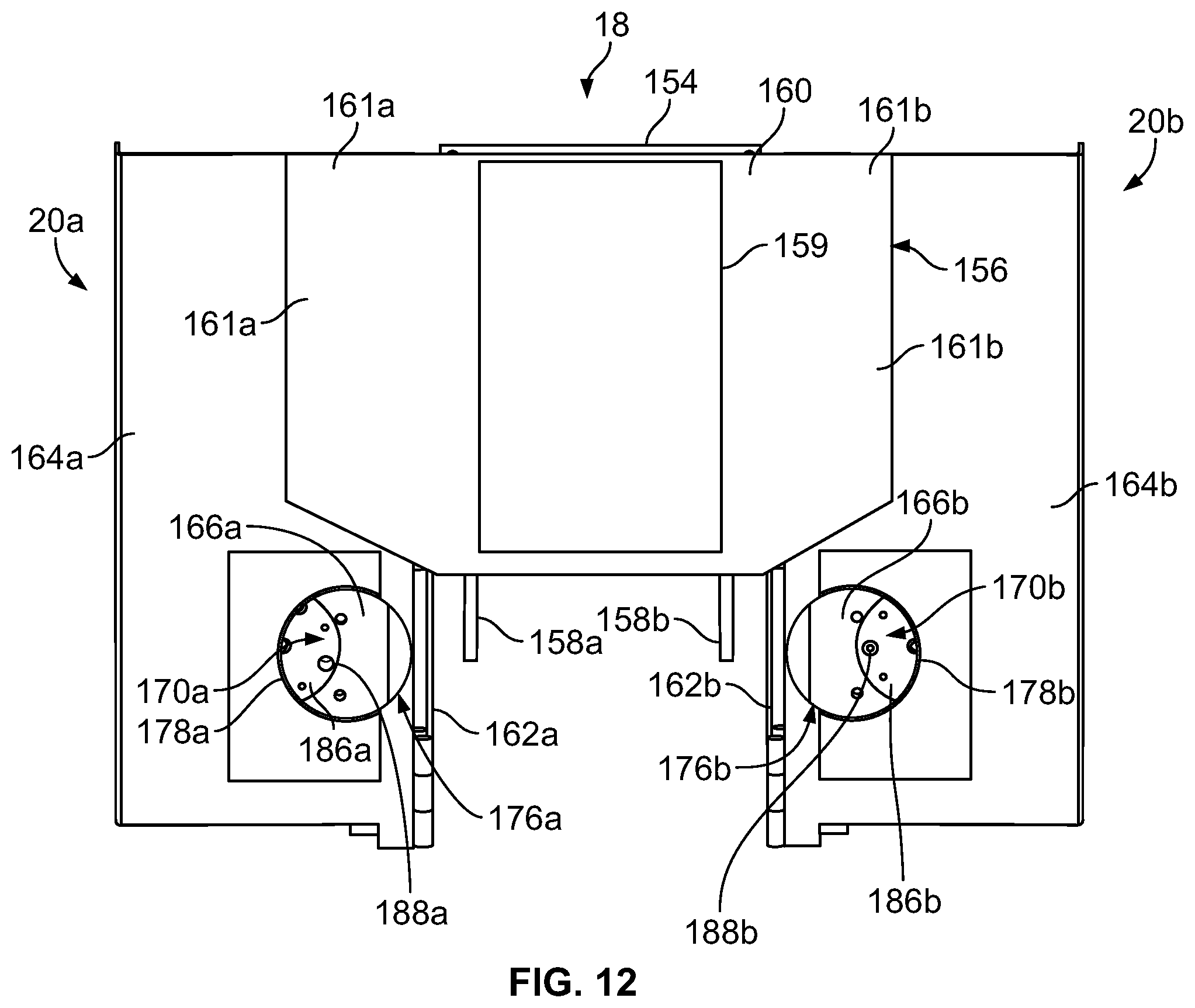
D00013

D00014

D00015

D00016
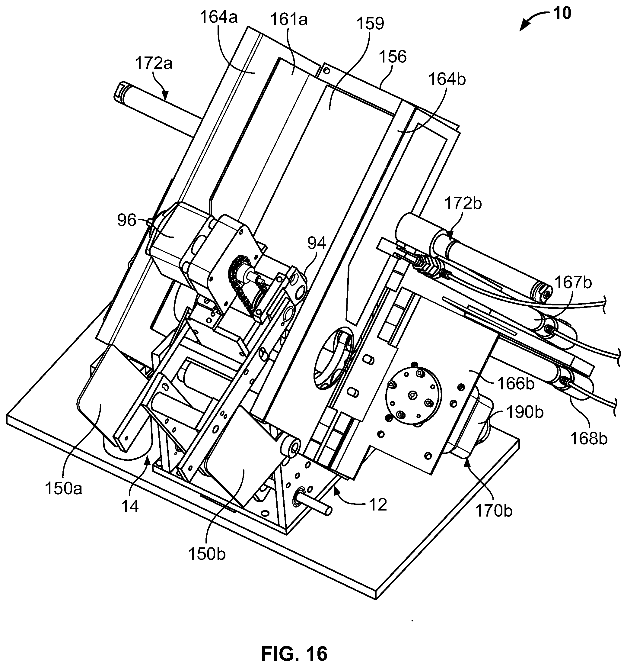
D00017

D00018

D00019
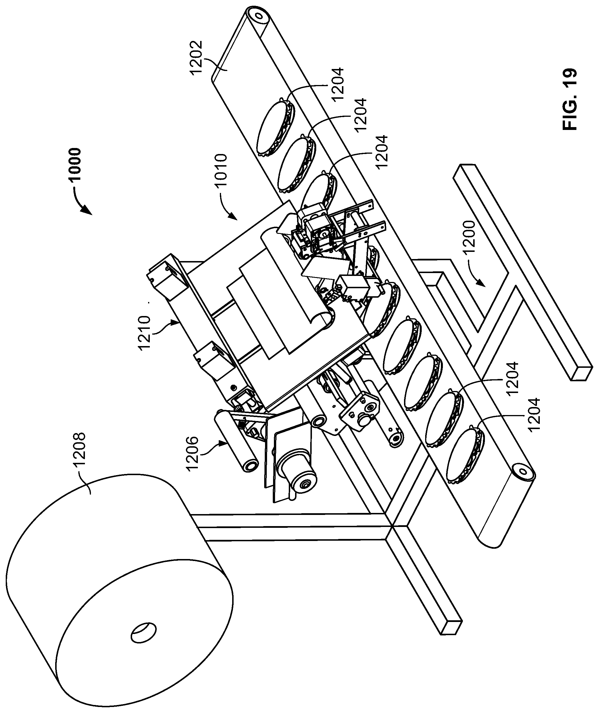
D00020

D00021
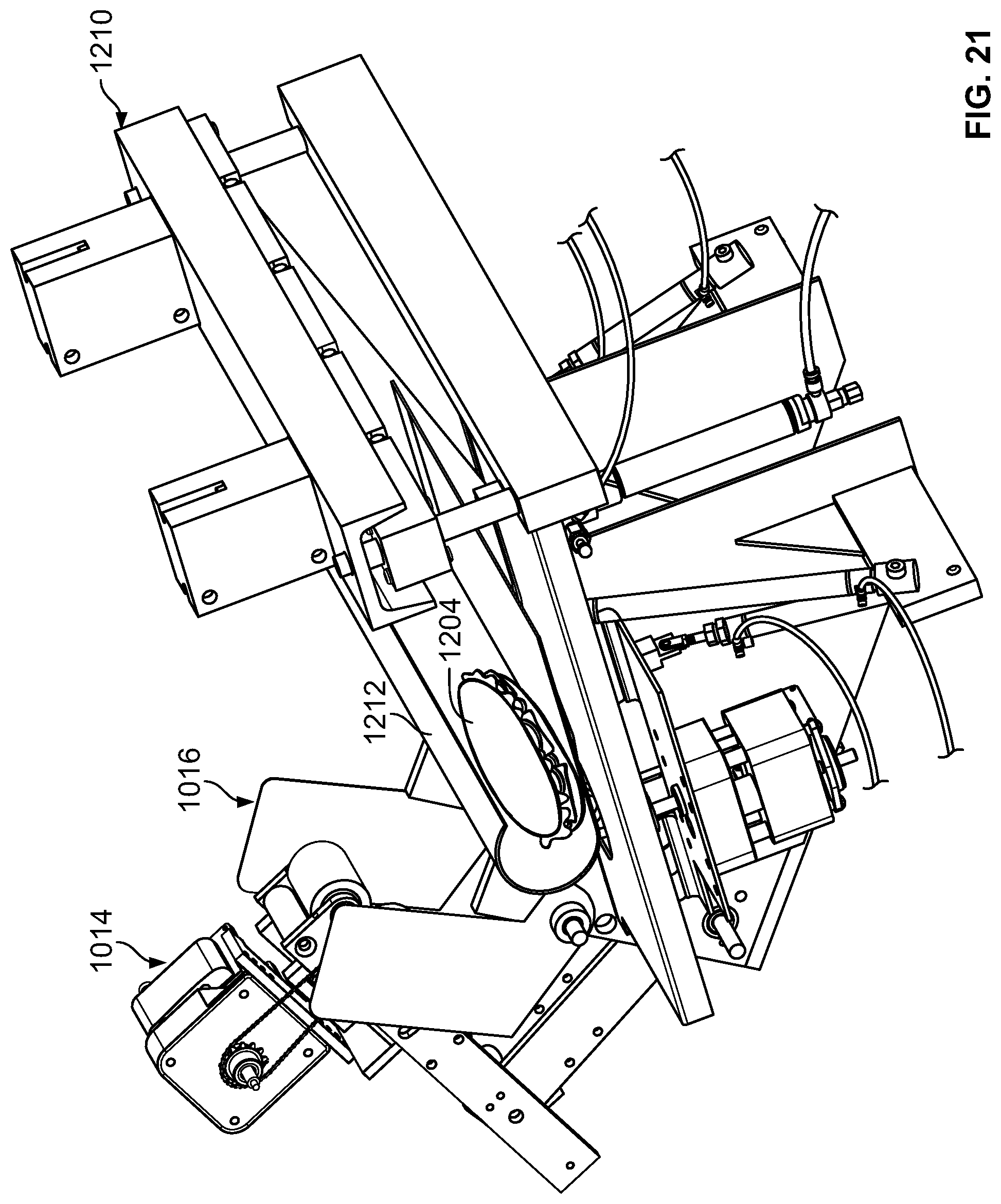
D00022

XML
uspto.report is an independent third-party trademark research tool that is not affiliated, endorsed, or sponsored by the United States Patent and Trademark Office (USPTO) or any other governmental organization. The information provided by uspto.report is based on publicly available data at the time of writing and is intended for informational purposes only.
While we strive to provide accurate and up-to-date information, we do not guarantee the accuracy, completeness, reliability, or suitability of the information displayed on this site. The use of this site is at your own risk. Any reliance you place on such information is therefore strictly at your own risk.
All official trademark data, including owner information, should be verified by visiting the official USPTO website at www.uspto.gov. This site is not intended to replace professional legal advice and should not be used as a substitute for consulting with a legal professional who is knowledgeable about trademark law.