Transforaminal intersomatic cage for an intervertebral fusion graft and an instrument for implanting the cage
Davis , et al. Sep
U.S. patent number 10,758,363 [Application Number 15/659,602] was granted by the patent office on 2020-09-01 for transforaminal intersomatic cage for an intervertebral fusion graft and an instrument for implanting the cage. This patent grant is currently assigned to LDR Medical. The grantee listed for this patent is LDR Medical. Invention is credited to Reginald J. Davis, Gregory A Hoffman, Jean Huppert, Kevin Kaufman, Alan W McGee, Hugues Mousselard, Ludovic Rillardon.


| United States Patent | 10,758,363 |
| Davis , et al. | September 1, 2020 |
Transforaminal intersomatic cage for an intervertebral fusion graft and an instrument for implanting the cage
Abstract
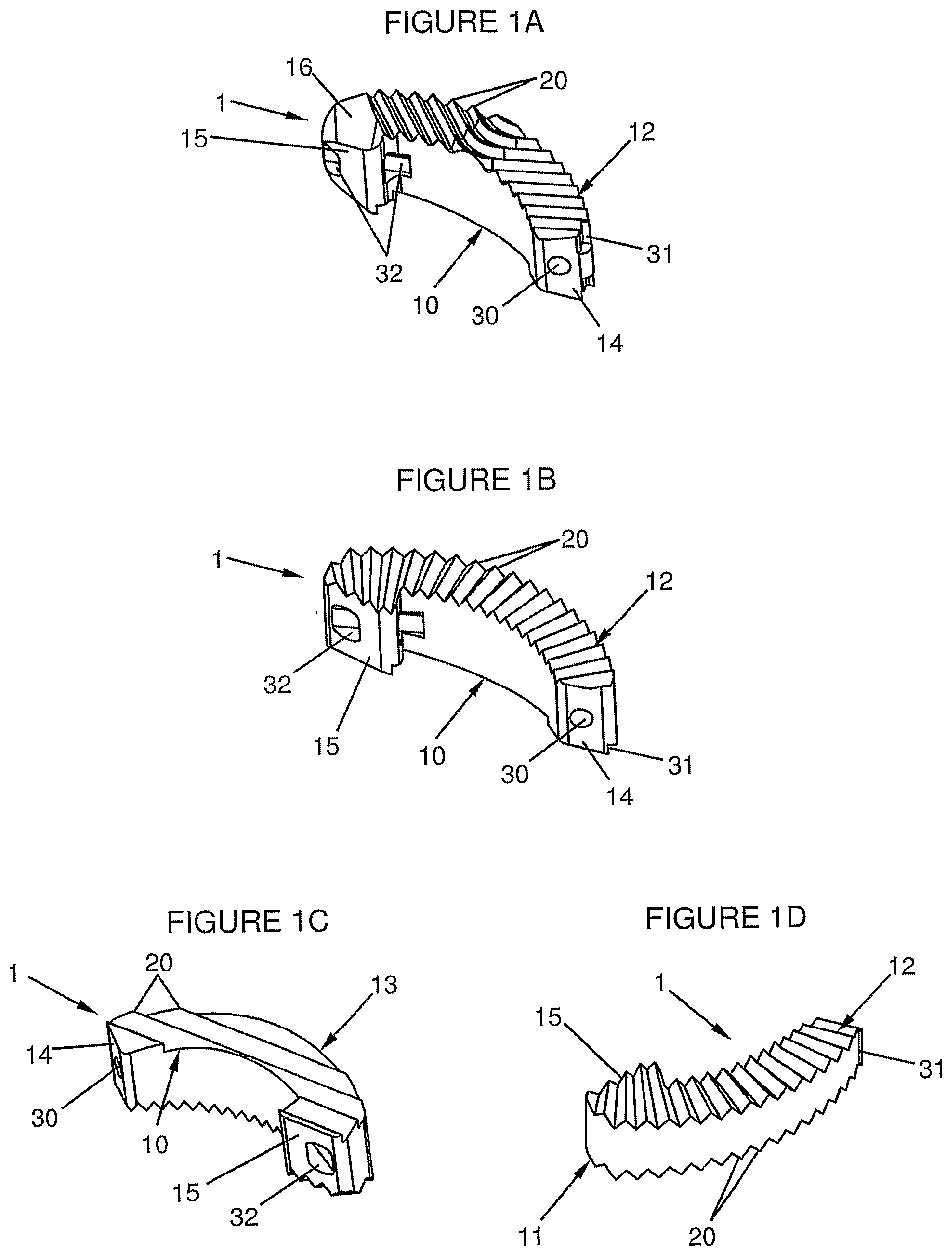
This disclosure presents various embodiments of a transforaminal intersomatic cage for an intervertebral fusion graft, and an instrument and method for implanting the cage, an embodiment of the cage having a body in the shape of a circular arc and comprising a lateral concave surface, a lateral convex surface, a straight upper surface, a straight lower surface and an end wall having at least one hole, called the end hole, designed to receive a rod of an instrument for implanting the cage between the vertebrae, wherein: the end hole has an orientation that is more or less tangential to the circular arc described by the body; the extremity opposite to the end wall of the body includes a return part extending the body toward the center of the circle on which the circular arc described by the body lies.
| Inventors: | Davis; Reginald J. (Cockeysville, MD), Kaufman; Kevin (Fort Worth, TX), Hoffman; Gregory A (Fort Wayne, IN), McGee; Alan W (Fort Wayne, IN), Huppert; Jean (L'etrat, FR), Mousselard; Hugues (Paris, FR), Rillardon; Ludovic (Le Raincy, FR) | ||||||||||
|---|---|---|---|---|---|---|---|---|---|---|---|
| Applicant: |
|
||||||||||
| Assignee: | LDR Medical (Rosieres Pres
Troyes, FR) |
||||||||||
| Family ID: | 37067404 | ||||||||||
| Appl. No.: | 15/659,602 | ||||||||||
| Filed: | July 25, 2017 |
Prior Publication Data
| Document Identifier | Publication Date | |
|---|---|---|
| US 20180008430 A1 | Jan 11, 2018 | |
Related U.S. Patent Documents
| Application Number | Filing Date | Patent Number | Issue Date | ||
|---|---|---|---|---|---|
| 13585063 | Jul 25, 2017 | 9713535 | |||
| 12279664 | 8241359 | ||||
| PCT/IB2007/000367 | Feb 15, 2007 | ||||
Foreign Application Priority Data
| Feb 15, 2006 [FR] | 06 01315 | |||
| Current U.S. Class: | 1/1 |
| Current CPC Class: | A61F 2/4455 (20130101); A61F 2/4611 (20130101); A61F 2002/30879 (20130101); A61F 2002/4627 (20130101); A61F 2230/0013 (20130101); A61F 2250/0098 (20130101); A61F 2002/30594 (20130101); A61F 2002/3008 (20130101); A61F 2002/30308 (20130101); A61F 2002/30131 (20130101); A61F 2002/30845 (20130101); A61F 2002/30579 (20130101); A61F 2002/2835 (20130101); A61F 2002/30192 (20130101); A61F 2002/30892 (20130101); A61F 2002/30795 (20130101); A61F 2002/30576 (20130101); A61F 2002/30894 (20130101); A61F 2230/0041 (20130101); A61F 2002/30884 (20130101); A61F 2230/0063 (20130101) |
| Current International Class: | A61F 2/44 (20060101); A61F 2/46 (20060101); A61F 2/28 (20060101); A61F 2/30 (20060101) |
References Cited [Referenced By]
U.S. Patent Documents
| 344683 | June 1886 | Sherer |
| 1025596 | May 1912 | Strawser |
| 1121484 | December 1914 | Crites |
| 3374786 | March 1968 | Callender, Jr. |
| 3791380 | February 1974 | Dawidowski |
| 3867728 | February 1975 | Stubstad et al. |
| 3875595 | April 1975 | Froning |
| 3892232 | July 1975 | Neufeld |
| 3948262 | April 1976 | Zaffaroni |
| 4009712 | March 1977 | Burstein et al. |
| 4135506 | January 1979 | Ulrich |
| 4175555 | November 1979 | Herbert |
| 4237875 | December 1980 | Termanini |
| 4349921 | September 1982 | Kuntz |
| 4379451 | April 1983 | Getscher |
| 4409974 | October 1983 | Freedland et al. |
| 4432358 | February 1984 | Fixel |
| 4488543 | December 1984 | Tornier |
| 4494535 | January 1985 | Haig |
| 4507115 | March 1985 | Kambara et al. |
| 4519100 | May 1985 | Wills et al. |
| 4561432 | December 1985 | Mazor |
| 4599086 | July 1986 | Doty |
| 4612920 | September 1986 | Lower |
| 4621629 | November 1986 | Koeneman |
| 4632101 | December 1986 | Freedland |
| 4653489 | March 1987 | Tronzo |
| 4657001 | April 1987 | Fixel |
| 4714469 | December 1987 | Kenna |
| 4721103 | January 1988 | Freedland |
| 4759352 | July 1988 | Lozier |
| 4787378 | November 1988 | Sodhi |
| 4790303 | December 1988 | Stefee |
| 4791918 | December 1988 | Von Hasselbach |
| 4820305 | April 1989 | Harms et al. |
| 4834757 | May 1989 | Brantigan |
| 4863476 | September 1989 | Shepperd |
| 4892545 | January 1990 | Day et al. |
| 4898156 | February 1990 | Gatturna et al. |
| 4904261 | February 1990 | Dove et al. |
| 4917704 | April 1990 | Frey et al. |
| 4919667 | April 1990 | Richmond |
| 4946468 | August 1990 | Li |
| 4955908 | September 1990 | Frey et al. |
| 4964403 | October 1990 | Karas et al. |
| 4968315 | November 1990 | Gatturna |
| 4969887 | November 1990 | Sodhi |
| 4973332 | November 1990 | Kummer |
| 4973333 | November 1990 | Treharne |
| 4997432 | March 1991 | Keller |
| 5002550 | March 1991 | Li |
| 5007910 | April 1991 | Anapliotis et al. |
| 5032125 | July 1991 | Durham et al. |
| 5041114 | August 1991 | Chapman et al. |
| 5041116 | August 1991 | Wilson |
| 5046513 | September 1991 | Gatturna et al. |
| 5057103 | October 1991 | Davis |
| 5062851 | November 1991 | Branemark |
| 5071437 | December 1991 | Steffee |
| 5087266 | February 1992 | Connell et al. |
| 5098433 | March 1992 | Freedland |
| 5116336 | May 1992 | Frigg |
| 5129901 | July 1992 | Decoste |
| 5176681 | January 1993 | Lawes et al. |
| 5192303 | March 1993 | Gatturna et al. |
| 5192327 | March 1993 | Brantigan |
| 5207679 | May 1993 | Li |
| 5217486 | June 1993 | Rice et al. |
| 5242448 | September 1993 | Pettine et al. |
| 5246458 | September 1993 | Graham |
| 5300074 | April 1994 | Frigg |
| 5306307 | April 1994 | Senter et al. |
| 5306309 | April 1994 | Wagner et al. |
| 5320644 | June 1994 | Baumgartner |
| 5324292 | June 1994 | Meyers |
| 5326205 | July 1994 | Anspach, Jr. et al. |
| 5342394 | August 1994 | Matsuno et al. |
| 5344459 | September 1994 | Swartz |
| 5356410 | October 1994 | Pennig |
| 5356413 | October 1994 | Martins et al. |
| 5372599 | December 1994 | Martins |
| 5397364 | March 1995 | Kozak et al. |
| 5417692 | May 1995 | Goble et al. |
| 5417712 | May 1995 | Whittaker et al. |
| 5425772 | June 1995 | Brantigan |
| 5429641 | July 1995 | Gotfried |
| 5437674 | August 1995 | Worcel |
| 5443514 | August 1995 | Steffee |
| 5456721 | October 1995 | Legrand |
| 5458601 | October 1995 | Young, Jr. et al. |
| 5458638 | October 1995 | Kuslich et al. |
| 5472452 | December 1995 | Trott |
| 5478342 | December 1995 | Kohrs |
| 5489210 | February 1996 | Hanosh |
| 5501695 | March 1996 | Anspach, Jr. et al. |
| 5507754 | April 1996 | Green et al. |
| 5507816 | April 1996 | Bullivant |
| 5522845 | June 1996 | Wenstrom, Jr. |
| 5522899 | June 1996 | Michelson |
| 5531792 | July 1996 | Huene |
| 5534004 | July 1996 | Santangelo |
| 5534029 | July 1996 | Shima |
| 5534030 | July 1996 | Navarro et al. |
| 5545229 | August 1996 | Parsons et al. |
| 5549617 | August 1996 | Green et al. |
| 5554191 | September 1996 | Lahille et al. |
| 5562689 | October 1996 | Green et al. |
| 5571104 | November 1996 | Li |
| 5571109 | November 1996 | Bertagnoli |
| 5571189 | November 1996 | Kuslich |
| 5578035 | November 1996 | Lin |
| 5591168 | January 1997 | Judet et al. |
| 5593409 | January 1997 | Michelson |
| 5609635 | March 1997 | Michelson |
| 5609636 | March 1997 | Kohrs et al. |
| 5613974 | March 1997 | Andreas et al. |
| 5620012 | April 1997 | Benderev et al. |
| 5643321 | July 1997 | Mcdevitt |
| 5658335 | August 1997 | Allen |
| 5683394 | November 1997 | Rinner |
| 5683463 | November 1997 | Godefroy et al. |
| 5702449 | December 1997 | Mckay |
| 5713899 | February 1998 | Marnay et al. |
| 5741253 | April 1998 | Michelson |
| 5755798 | May 1998 | Papavero et al. |
| 5766252 | June 1998 | Henry et al. |
| 5766253 | June 1998 | Brosnahan, III |
| 5772661 | June 1998 | Michelson |
| 5776199 | July 1998 | Michelson |
| 5782830 | July 1998 | Farris |
| 5782919 | July 1998 | Zdeblick et al. |
| 5797909 | August 1998 | Michelson |
| 5800547 | September 1998 | Schafer et al. |
| 5800550 | September 1998 | Sertich |
| 5810820 | September 1998 | Santori et al. |
| 5849004 | December 1998 | Bramlet |
| 5860973 | January 1999 | Michelson |
| 5861041 | January 1999 | Tienboon |
| 5865845 | February 1999 | Thalgott |
| 5888222 | March 1999 | Coates et al. |
| 5888223 | March 1999 | Bray, Jr. |
| 5888224 | March 1999 | Beckers et al. |
| 5888227 | March 1999 | Cottle |
| 5888228 | March 1999 | Knothe et al. |
| 5895427 | April 1999 | Kuslich et al. |
| 5897556 | April 1999 | Drewry et al. |
| 5968098 | October 1999 | Winslow |
| 5976139 | November 1999 | Bramlet |
| 5980522 | November 1999 | Koros et al. |
| 5984967 | November 1999 | Zdeblick et al. |
| 5989289 | November 1999 | Coates et al. |
| 6001130 | December 1999 | Bryan et al. |
| 6033438 | March 2000 | Bianchi et al. |
| 6039762 | March 2000 | McKay |
| 6045579 | April 2000 | Hochshuler et al. |
| 6059787 | May 2000 | Allen |
| 6059829 | May 2000 | Schlapfer et al. |
| 6063121 | May 2000 | Xavier et al. |
| 6066174 | May 2000 | Farris |
| 6066175 | May 2000 | Henderson et al. |
| 6080158 | June 2000 | Lin |
| 6080193 | June 2000 | Hochshuler et al. |
| 6093205 | July 2000 | Mcleod et al. |
| 6096038 | August 2000 | Michelson |
| 6096080 | August 2000 | Nicholson et al. |
| 6099531 | August 2000 | Bonutti |
| 6102950 | August 2000 | Vaccaro |
| 6111164 | August 2000 | Rainey et al. |
| 6113637 | September 2000 | Gill et al. |
| 6113638 | September 2000 | Williams et al. |
| 6120502 | September 2000 | Michelson |
| 6123705 | September 2000 | Michelson |
| 6129763 | October 2000 | Chauvin et al. |
| 6136031 | October 2000 | Middleton |
| 6143032 | November 2000 | Schafer et al. |
| 6146421 | November 2000 | Gordon et al. |
| 6149650 | November 2000 | Michelson |
| 6156067 | December 2000 | Bryan et al. |
| 6174311 | January 2001 | Branch et al. |
| 6179873 | January 2001 | Zientek |
| 6179875 | January 2001 | Von Strempel |
| 6183474 | February 2001 | Bramlet et al. |
| 6193757 | February 2001 | Foley et al. |
| 6206922 | March 2001 | Zdeblick et al. |
| 6206923 | March 2001 | Boyd et al. |
| 6210412 | April 2001 | Michelson |
| 6210442 | April 2001 | Wing et al. |
| 6214050 | April 2001 | Huene |
| 6224595 | May 2001 | Michelson |
| 6231610 | May 2001 | Geisler |
| 6235059 | May 2001 | Benezech et al. |
| 6241733 | June 2001 | Nicholson et al. |
| 6241769 | June 2001 | Nicholson et al. |
| 6241770 | June 2001 | Michelson |
| 6241771 | June 2001 | Gresser et al. |
| 6245072 | June 2001 | Zdeblick et al. |
| 6245108 | June 2001 | Biscup |
| 6251140 | June 2001 | Marino et al. |
| 6258089 | July 2001 | Campbell et al. |
| 6258094 | July 2001 | Nicholson et al. |
| 6258125 | July 2001 | Paul et al. |
| 6261293 | July 2001 | Nicholson et al. |
| 6261295 | July 2001 | Nicholson et al. |
| 6264656 | July 2001 | Michelson |
| 6267764 | July 2001 | Elberg |
| 6270498 | August 2001 | Michelson et al. |
| 6277149 | August 2001 | Boyle et al. |
| 6296664 | October 2001 | Middleton |
| 6302914 | October 2001 | Michelson |
| 6306170 | October 2001 | Ray |
| 6315797 | November 2001 | Middleton |
| 6342074 | January 2002 | Simpson |
| 6348071 | February 2002 | Steffee et al. |
| 6350283 | February 2002 | Michelson |
| 6364880 | April 2002 | Michelson |
| 6371987 | April 2002 | Weiland et al. |
| 6371988 | April 2002 | Pafford et al. |
| 6375655 | April 2002 | Zdeblick et al. |
| 6383186 | May 2002 | Michelson |
| 6395031 | May 2002 | Foley et al. |
| 6395035 | May 2002 | Bresina et al. |
| 6402750 | June 2002 | Atkinson et al. |
| 6402785 | June 2002 | Zdeblick et al. |
| 6409765 | June 2002 | Bianchi et al. |
| 6419703 | July 2002 | Fallin et al. |
| 6419704 | July 2002 | Ferree |
| 6423063 | July 2002 | Bonutti |
| 6423095 | July 2002 | Van Hoeck et al. |
| 6432106 | August 2002 | Fraser |
| 6432107 | August 2002 | Ferree |
| 6447512 | September 2002 | Landry et al. |
| 6447544 | September 2002 | Michelson |
| 6447546 | September 2002 | Bramlet et al. |
| 6447547 | September 2002 | Michelson |
| 6454769 | September 2002 | Wagner et al. |
| 6458159 | October 2002 | Thalgott |
| 6461359 | October 2002 | Tribus |
| 6468310 | October 2002 | Ralph et al. |
| 6471724 | October 2002 | Zdeblick et al. |
| 6478823 | November 2002 | Michelson |
| 6482233 | November 2002 | Aebi et al. |
| 6482584 | November 2002 | Mills et al. |
| 6485517 | November 2002 | Michelson |
| 6497726 | December 2002 | Carter et al. |
| 6500205 | December 2002 | Michelson |
| 6524312 | February 2003 | Landry et al. |
| 6527803 | March 2003 | Crozet et al. |
| 6527806 | March 2003 | Ralph et al. |
| 6540753 | April 2003 | Cohen |
| 6540785 | April 2003 | Gill et al. |
| 6554863 | April 2003 | Paul et al. |
| 6558423 | May 2003 | Michelson |
| 6558424 | May 2003 | Thalgott |
| 6565605 | May 2003 | Goble et al. |
| 6576016 | June 2003 | Hochshuler et al. |
| 6579291 | June 2003 | Keith et al. |
| 6582468 | June 2003 | Gauchet |
| 6592624 | July 2003 | Fraser et al. |
| 6599320 | July 2003 | Kuslich |
| 6605089 | August 2003 | Michelson |
| 6607530 | August 2003 | Carl et al. |
| 6610065 | August 2003 | Branch et al. |
| 6610089 | August 2003 | Liu et al. |
| 6610092 | August 2003 | Ralph et al. |
| 6613091 | September 2003 | Zdeblick et al. |
| 6613278 | September 2003 | Mills et al. |
| 6616671 | September 2003 | Landry et al. |
| 6620163 | September 2003 | Michelson |
| 6635086 | October 2003 | Lin |
| 6635087 | October 2003 | Angelucci et al. |
| 6645206 | November 2003 | Zdeblick et al. |
| 6645249 | November 2003 | Ralph et al. |
| 6648893 | November 2003 | Dudasik |
| 6652584 | November 2003 | Michelson |
| 6652818 | November 2003 | Mills et al. |
| 6660038 | December 2003 | Boyer, II et al. |
| 6666890 | December 2003 | Michelson |
| 6669730 | December 2003 | Ralph et al. |
| 6669731 | December 2003 | Ralph et al. |
| 6673113 | January 2004 | Ralph et al. |
| 6676703 | January 2004 | Biscup |
| 6679887 | January 2004 | Nicholson et al. |
| 6679915 | January 2004 | Cauthen |
| 6695846 | February 2004 | Richelsoph et al. |
| 6695851 | February 2004 | Zdeblick et al. |
| 6695882 | February 2004 | Bianchi et al. |
| 6706067 | March 2004 | Shimp et al. |
| 6709458 | March 2004 | Michelson |
| 6712818 | March 2004 | Michelson |
| 6716247 | April 2004 | Michelson |
| 6719794 | April 2004 | Gerber et al. |
| 6723128 | April 2004 | Uk |
| 6733504 | May 2004 | Lin et al. |
| 6733531 | May 2004 | Trieu |
| 6733535 | May 2004 | Michelson |
| 6736850 | May 2004 | Davis |
| 6740117 | May 2004 | Ralph et al. |
| 6740118 | May 2004 | Eisermann et al. |
| 6743255 | June 2004 | Ferree |
| 6743256 | June 2004 | Mason |
| 6743257 | June 2004 | Castro |
| 6749636 | June 2004 | Michelson |
| 6758849 | July 2004 | Michelson |
| 6767367 | July 2004 | Michelson |
| 6770074 | August 2004 | Michelson |
| 6770096 | August 2004 | Bolger et al. |
| 6793679 | September 2004 | Michelson |
| RE38614 | October 2004 | Paul et al. |
| 6800092 | October 2004 | Williams et al. |
| 6800093 | October 2004 | Nicholson et al. |
| 6805713 | October 2004 | Carter et al. |
| 6805714 | October 2004 | Sutcliffe |
| 6808537 | October 2004 | Michelson |
| 6835206 | December 2004 | Jackson |
| 6849093 | February 2005 | Michelson |
| 6890355 | May 2005 | Michelson |
| 6902580 | June 2005 | Fallin et al. |
| 6923811 | August 2005 | Carl et al. |
| 6923830 | August 2005 | Michelson |
| 6955691 | October 2005 | Chae et al. |
| 6962606 | November 2005 | Michelson |
| 6964687 | November 2005 | Bernard et al. |
| 6972019 | December 2005 | Michelson |
| 6972035 | December 2005 | Michelson |
| 6981975 | January 2006 | Michelson |
| 6984234 | January 2006 | Bray |
| 6994727 | February 2006 | Khandkar et al. |
| 7001385 | February 2006 | Bonutti |
| 7008453 | March 2006 | Michelson |
| 7018412 | March 2006 | Ferreira et al. |
| 7033394 | April 2006 | Michelson |
| 7041135 | May 2006 | Michelson |
| 7041136 | May 2006 | Goble et al. |
| 7048762 | May 2006 | Sander et al. |
| 7048765 | May 2006 | Grooms et al. |
| 7051610 | May 2006 | Stoianovici et al. |
| 7060097 | June 2006 | Fraser et al. |
| 7063701 | June 2006 | Michelson |
| 7063702 | June 2006 | Michelson |
| 7066961 | June 2006 | Michelson |
| 7074237 | July 2006 | Goble et al. |
| 7090698 | August 2006 | Goble et al. |
| 7094239 | August 2006 | Michelson |
| 7112206 | September 2006 | Michelson |
| 7118579 | October 2006 | Michelson |
| 7118598 | October 2006 | Michelson |
| 7128760 | October 2006 | Michelson |
| 7128761 | October 2006 | Kuras et al. |
| 7137984 | November 2006 | Michelson |
| 7153325 | December 2006 | Kim et al. |
| 7163561 | January 2007 | Michelson |
| 7172627 | February 2007 | Fiere et al. |
| 7211112 | May 2007 | Baynham et |
| 7217291 | May 2007 | Zucherman et al. |
| 7217293 | May 2007 | Branch |
| 7223289 | May 2007 | Trieu et al. |
| 7232463 | June 2007 | Falahee |
| 7232464 | June 2007 | Mathieu et al. |
| 7235082 | June 2007 | Bartish et al. |
| 7255698 | August 2007 | Michelson |
| 7276081 | October 2007 | Coates et al. |
| 7291170 | November 2007 | Huppert |
| 7303583 | December 2007 | Schar et al. |
| 7326248 | February 2008 | Michelson |
| 7361196 | April 2008 | Fallin et al. |
| 7410501 | August 2008 | Michelson |
| 7431735 | October 2008 | Liu et al. |
| 7435262 | October 2008 | Michelson |
| 7442209 | October 2008 | Michelson |
| 7445636 | October 2008 | Liu et al. |
| 7445635 | November 2008 | Fallin et al. |
| 7455684 | November 2008 | Gradel et al. |
| 7455692 | November 2008 | Michelson |
| 7465317 | December 2008 | Malberg et al. |
| 7470273 | December 2008 | Dougherty-Shah |
| 7473276 | January 2009 | Aebi et al. |
| 7479160 | January 2009 | Branch et al. |
| 7503933 | March 2009 | Michelson |
| 7540882 | June 2009 | Michelson |
| 7563284 | July 2009 | Coppes et al. |
| 7563286 | July 2009 | Gerber et al. |
| 7566345 | July 2009 | Fallin et al. |
| 7588590 | September 2009 | Chervitz et al. |
| 7591851 | September 2009 | Winslow et al. |
| 7594931 | September 2009 | Louis et al. |
| 7594932 | September 2009 | Aferzon et al. |
| 7601170 | October 2009 | Winslow et al. |
| 7604654 | October 2009 | Fallin et al. |
| 7608107 | October 2009 | Michelson |
| 7611538 | November 2009 | Belliard et al. |
| 7618453 | November 2009 | Goble et al. |
| 7618455 | November 2009 | Goble et al. |
| 7618456 | November 2009 | Mathieu et al. |
| 7621955 | November 2009 | Goble et al. |
| 7621958 | November 2009 | Zdeblick et al. |
| 7625393 | December 2009 | Fallin et al. |
| 7637951 | December 2009 | Michelson |
| 7637953 | December 2009 | Branch et al. |
| 7637954 | December 2009 | Michelson |
| 7641690 | January 2010 | Abdou |
| 7655027 | February 2010 | Michelson |
| 7658766 | February 2010 | Melkent et al. |
| 7682396 | March 2010 | Beaurain et al. |
| 7695516 | April 2010 | Zeegers |
| 7695517 | April 2010 | Benzel et al. |
| 7727280 | June 2010 | McLuen |
| 7744602 | June 2010 | Teeny et al. |
| 7749252 | July 2010 | Zucherman et al. |
| 7749274 | July 2010 | Razian |
| 7753937 | July 2010 | Chervitz et al. |
| 7771473 | August 2010 | Thramann |
| 7771475 | August 2010 | Michelson |
| 7776090 | August 2010 | Winslow et al. |
| 7780670 | August 2010 | Bonutti |
| 7789914 | September 2010 | Michelson |
| 7794502 | September 2010 | Michelson |
| 7799053 | September 2010 | Haid, Jr. et al. |
| 7799057 | September 2010 | Hudgins et al. |
| 7799081 | September 2010 | McKinley |
| 7811326 | October 2010 | Braddock, Jr. et al. |
| 7819903 | October 2010 | Fraser et al. |
| 7824445 | November 2010 | Biro et al. |
| 7833255 | November 2010 | Chow et al. |
| 7842088 | November 2010 | Rashbaum et al. |
| 7846188 | December 2010 | Moskowitz et al. |
| 7846207 | December 2010 | Lechmann et al. |
| 7850731 | December 2010 | Brittan et al. |
| 7850732 | December 2010 | Heinz |
| 7850733 | December 2010 | Baynham et al. |
| 7862616 | January 2011 | Lechmann et al. |
| 7871441 | January 2011 | Eckman |
| 7875076 | January 2011 | Mathieu et al. |
| 7887591 | February 2011 | Aebi et al. |
| 7892261 | February 2011 | Bonutti |
| 7892286 | February 2011 | Michelson |
| 7905886 | March 2011 | Curran et al. |
| 7909871 | March 2011 | Abdou |
| 7914560 | March 2011 | Hoy et al. |
| 7922729 | April 2011 | Michelson |
| 7931674 | April 2011 | Zucherman et al. |
| 7931840 | April 2011 | Michelson |
| 7935149 | May 2011 | Michelson |
| 7951198 | May 2011 | Sucec et al. |
| 7955390 | June 2011 | Fallin et al. |
| 7972337 | July 2011 | Boyajian et al. |
| 7972363 | July 2011 | Moskowitz et al. |
| 7972365 | July 2011 | Michelson |
| 7976566 | July 2011 | Michelson |
| 7985255 | July 2011 | Bray et al. |
| 7985258 | July 2011 | Zdeblick et al. |
| 7993373 | August 2011 | Hoy et al. |
| 7998177 | August 2011 | Hoy et al. |
| 7998178 | August 2011 | Hoy et al. |
| 7998211 | August 2011 | Baccelli et al. |
| 8007534 | August 2011 | Michelson |
| 8021401 | September 2011 | Carl et al. |
| 8021430 | September 2011 | Michelson |
| 8043334 | October 2011 | Fisher et al. |
| 8062336 | November 2011 | Triplett et al. |
| 8062375 | November 2011 | Glerum et al. |
| 8066741 | November 2011 | Fallin et al. |
| 8066749 | November 2011 | Winslow et al. |
| 8070816 | December 2011 | Taylor |
| 8070819 | December 2011 | Aferzon et al. |
| 8075593 | December 2011 | Hess |
| 8075618 | December 2011 | Trieu et al. |
| 8075621 | December 2011 | Michelson |
| 8080062 | December 2011 | Armstrong et al. |
| 8097034 | January 2012 | Michelson |
| 8114082 | February 2012 | Boyajian et al. |
| 8118873 | February 2012 | Humphreys et al. |
| 8137405 | March 2012 | Kostuik et al. |
| 8147556 | April 2012 | Louis et al. |
| 8167946 | May 2012 | Michelson |
| 8167949 | May 2012 | Tyber et al. |
| 8167950 | May 2012 | Aferzon et al. |
| 8182539 | May 2012 | Tyber et al. |
| 8187329 | May 2012 | Theofilos |
| 8187332 | May 2012 | Mcluen |
| 8216312 | July 2012 | Gray |
| 8221422 | July 2012 | Mangione |
| 8241359 | August 2012 | Davis et al. |
| 8257443 | September 2012 | Kamran et al. |
| 8262700 | September 2012 | Cho et al. |
| 8267999 | September 2012 | Beaurain et al. |
| 8303663 | November 2012 | Jimenez et al. |
| 8313528 | November 2012 | Wensel |
| 8323345 | December 2012 | Sledge |
| 8343197 | January 2013 | Gonzalez-Hernandez |
| 8343219 | January 2013 | Allain et al. |
| 8349015 | January 2013 | Bae et al. |
| 8409288 | April 2013 | Davis et al. |
| 8535352 | September 2013 | Altarac et al. |
| 8545563 | October 2013 | Brun et al. |
| 8617245 | December 2013 | Brett |
| 8696681 | April 2014 | Harris et al. |
| 9044337 | June 2015 | Dinville et al. |
| 9566164 | February 2017 | Zeegers |
| 9597198 | March 2017 | Davis et al. |
| 9713535 | July 2017 | Davis et al. |
| 9763803 | September 2017 | Dinville et al. |
| 2001/0018614 | August 2001 | Bianchi |
| 2001/0020185 | September 2001 | Ray |
| 2001/0031254 | October 2001 | Bianchi et al. |
| 2001/0031967 | October 2001 | Nicholson et al. |
| 2002/0016592 | February 2002 | Branch et al. |
| 2002/0026243 | February 2002 | Lin |
| 2002/0032483 | March 2002 | Nicholson et al. |
| 2002/0040243 | April 2002 | Attali et al. |
| 2002/0059938 | May 2002 | Fogarty et al. |
| 2002/0070565 | June 2002 | Szapucki et al. |
| 2002/0072806 | June 2002 | Buskirk et al. |
| 2002/0082597 | June 2002 | Fraser |
| 2002/0082700 | June 2002 | Bianchi et al. |
| 2002/0087212 | July 2002 | James et al. |
| 2002/0106393 | August 2002 | Bianchi et al. |
| 2002/0107572 | August 2002 | Foley et al. |
| 2002/0119437 | August 2002 | Grroms et al. |
| 2002/0138143 | September 2002 | Grooms et al. |
| 2002/0151893 | October 2002 | Santilli |
| 2002/0161444 | October 2002 | Choi |
| 2002/0165612 | November 2002 | Gerber et al. |
| 2002/0165613 | November 2002 | Lin et al. |
| 2002/0193880 | December 2002 | Fraser |
| 2003/0023304 | January 2003 | Carter et al. |
| 2003/0027125 | February 2003 | Mills et al. |
| 2003/0028249 | February 2003 | Baccelli et al. |
| 2003/0060886 | March 2003 | Van Hoeck et al. |
| 2003/0069640 | April 2003 | Ferreira et al. |
| 2003/0074075 | April 2003 | Thomas, Jr. et al. |
| 2003/0097179 | May 2003 | Carter et al. |
| 2003/0100950 | May 2003 | Moret |
| 2003/0109928 | June 2003 | Pasquet et al. |
| 2003/0135279 | July 2003 | Michelson |
| 2003/0139815 | July 2003 | Grooms et al. |
| 2003/0149438 | August 2003 | Nichols et al. |
| 2003/0149484 | August 2003 | Michelson |
| 2003/0167091 | September 2003 | Scharf |
| 2003/0187436 | October 2003 | Bolger et al. |
| 2003/0191531 | October 2003 | Berry et al. |
| 2003/0195514 | October 2003 | Trieu et al. |
| 2003/0195626 | October 2003 | Huppert |
| 2003/0195629 | October 2003 | Pafford et al. |
| 2003/0195632 | October 2003 | Foley et al. |
| 2003/0204260 | October 2003 | Ferree |
| 2003/0233147 | December 2003 | Nicholson et al. |
| 2004/0010312 | January 2004 | Enayati |
| 2004/0030387 | February 2004 | Landry et al. |
| 2004/0073307 | April 2004 | Keller |
| 2004/0073309 | April 2004 | Bianchi et al. |
| 2004/0073313 | April 2004 | Link et al. |
| 2004/0093083 | May 2004 | Branch et al. |
| 2004/0097929 | May 2004 | Branch et al. |
| 2004/0115172 | June 2004 | Bianchi et al. |
| 2004/0117022 | June 2004 | Marnay et al. |
| 2004/0127990 | July 2004 | Charles, Jr. et al. |
| 2004/0127993 | July 2004 | Kast et al. |
| 2004/0127994 | July 2004 | Kast et al. |
| 2004/0148029 | July 2004 | Bianchi et al. |
| 2004/0162617 | August 2004 | Zucherman et al. |
| 2004/0172020 | September 2004 | Beaurain et al. |
| 2004/0172130 | September 2004 | Nakahara et al. |
| 2004/0199254 | October 2004 | Louis et al. |
| 2004/0210219 | October 2004 | Bray |
| 2004/0210227 | October 2004 | Trail et al. |
| 2004/0210308 | October 2004 | Carter et al. |
| 2004/0210313 | October 2004 | Michelson |
| 2004/0230306 | November 2004 | Hoeck et al. |
| 2004/0243238 | December 2004 | Arnin et al. |
| 2004/0243240 | December 2004 | Beaurain et al. |
| 2004/0254577 | December 2004 | Delecrin et al. |
| 2004/0254643 | December 2004 | Jackson |
| 2005/0004672 | January 2005 | Pafford et al. |
| 2005/0010215 | January 2005 | Delecrin et al. |
| 2005/0015149 | January 2005 | Michelson |
| 2005/0027359 | February 2005 | Mashburn |
| 2005/0027360 | February 2005 | Webb et al. |
| 2005/0027362 | February 2005 | Williams et al. |
| 2005/0038511 | February 2005 | Martz et al. |
| 2005/0038512 | February 2005 | Michelson |
| 2005/0049590 | March 2005 | Alleyne et al. |
| 2005/0060034 | March 2005 | Berry et al. |
| 2005/0060037 | March 2005 | Michelson |
| 2005/0065608 | March 2005 | Michelson |
| 2005/0065611 | March 2005 | Huppert et al. |
| 2005/0085917 | April 2005 | Marnay et al. |
| 2005/0096742 | May 2005 | Mills et al. |
| 2005/0096745 | May 2005 | Andre et al. |
| 2005/0100862 | May 2005 | Mills et al. |
| 2005/0101957 | May 2005 | Buskirk et al. |
| 2005/0107788 | May 2005 | Beaurain et al. |
| 2005/0119744 | June 2005 | Buskirk et al. |
| 2005/0119747 | June 2005 | Fabris Monterumici et al. |
| 2005/0143733 | June 2005 | Petit |
| 2005/0143825 | June 2005 | Enayati |
| 2005/0149189 | July 2005 | Mokhtar et al. |
| 2005/0165483 | July 2005 | Ray, III et al. |
| 2005/0171554 | August 2005 | Estes et al. |
| 2005/0177236 | August 2005 | Mathieu et al. |
| 2005/0197706 | September 2005 | Hovorka et al. |
| 2005/0246024 | November 2005 | Zeegers |
| 2005/0283236 | December 2005 | Razian |
| 2005/0288788 | December 2005 | Dougherty-shah |
| 2006/0058878 | March 2006 | Michelson |
| 2006/0069437 | March 2006 | Weber |
| 2006/0085071 | April 2006 | Lechmann et al. |
| 2006/0085076 | April 2006 | Krishna et al. |
| 2006/0089717 | April 2006 | Krishna et al. |
| 2006/0095136 | May 2006 | Mcluen |
| 2006/0121084 | June 2006 | Borden et al. |
| 2006/0122703 | June 2006 | Aebi et al. |
| 2006/0129244 | June 2006 | Ensign |
| 2006/0136063 | June 2006 | Zeegers |
| 2006/0142863 | June 2006 | Fraser et al. |
| 2006/0155377 | July 2006 | Beaurain et al. |
| 2006/0173544 | August 2006 | Gau |
| 2006/0186063 | August 2006 | Campbell |
| 2006/0206208 | September 2006 | Michelson |
| 2006/0235426 | October 2006 | Lim et al. |
| 2006/0241621 | October 2006 | Moskowitz et al. |
| 2006/0241761 | October 2006 | Gately |
| 2006/0241764 | October 2006 | Michelson |
| 2006/0253201 | November 2006 | Mcluen |
| 2006/0276899 | December 2006 | Zipnick et al. |
| 2006/0282074 | December 2006 | Renaud et al. |
| 2007/0016217 | January 2007 | Dinville |
| 2007/0016297 | January 2007 | Johnson |
| 2007/0032871 | February 2007 | Michelson |
| 2007/0049943 | March 2007 | Moskowitz et al. |
| 2007/0073404 | March 2007 | Rashbaum et al. |
| 2007/0093850 | April 2007 | Harris |
| 2007/0106388 | May 2007 | Michelson |
| 2007/0142843 | June 2007 | Dye |
| 2007/0162128 | July 2007 | DeRidder et al. |
| 2007/0162130 | July 2007 | Rashbaum et al. |
| 2007/0179623 | August 2007 | Trieu et al. |
| 2007/0208345 | September 2007 | Marnay et al. |
| 2007/0233253 | October 2007 | Bray et al. |
| 2007/0250167 | October 2007 | Bray et al. |
| 2007/0260249 | November 2007 | Boyajian et al. |
| 2007/0270951 | November 2007 | Davis et al. |
| 2007/0270954 | November 2007 | Wu |
| 2007/0270960 | November 2007 | Bonin, Jr. et al. |
| 2007/0270961 | November 2007 | Ferguson |
| 2007/0270967 | November 2007 | Fallin et al. |
| 2007/0276498 | November 2007 | Aebi et al. |
| 2008/0021562 | January 2008 | Huppert |
| 2008/0027547 | January 2008 | Yu et al. |
| 2008/0027550 | January 2008 | Link et al. |
| 2008/0033432 | February 2008 | Mcgraw et al. |
| 2008/0033562 | February 2008 | Krishna et al. |
| 2008/0051887 | February 2008 | Carter et al. |
| 2008/0109083 | May 2008 | Van Hoeck et al. |
| 2008/0125865 | May 2008 | Abdelgany |
| 2008/0132949 | June 2008 | Aferzon et al. |
| 2008/0161933 | July 2008 | Grotz et al. |
| 2008/0177306 | July 2008 | Lamborne et al. |
| 2008/0195211 | August 2008 | Lin et al. |
| 2008/0200984 | August 2008 | Jodaitis et al. |
| 2008/0234686 | September 2008 | Beaurain et al. |
| 2008/0249569 | October 2008 | Waugh et al. |
| 2008/0249575 | October 2008 | Waugh et al. |
| 2008/0249625 | October 2008 | Waugh et al. |
| 2008/0255617 | October 2008 | Cho et al. |
| 2008/0281425 | November 2008 | Thalgott et al. |
| 2008/0294260 | November 2008 | Gray |
| 2008/0300634 | December 2008 | Gray |
| 2008/0300685 | December 2008 | Carls et al. |
| 2008/0306596 | December 2008 | Jones et al. |
| 2008/0312743 | December 2008 | Villa et al. |
| 2009/0030461 | January 2009 | Hoy et al. |
| 2009/0030519 | January 2009 | Falahee |
| 2009/0030520 | January 2009 | Biedermann et al. |
| 2009/0099601 | April 2009 | Aferzon et al. |
| 2009/0099604 | April 2009 | Cho et al. |
| 2009/0105830 | April 2009 | Jones et al. |
| 2009/0105831 | April 2009 | Jones et al. |
| 2009/0105832 | April 2009 | Allain et al. |
| 2009/0112271 | April 2009 | Moskowitz et al. |
| 2009/0118771 | May 2009 | Gonzalez-Hernandez |
| 2009/0125071 | May 2009 | Skinlo et al. |
| 2009/0132054 | May 2009 | Zeegers |
| 2009/0157188 | June 2009 | Zeegers |
| 2009/0164020 | June 2009 | Janowski et al. |
| 2009/0182381 | July 2009 | Beaurain et al. |
| 2009/0182429 | July 2009 | Humphreys et al. |
| 2009/0182430 | July 2009 | Tyber et al. |
| 2009/0186333 | July 2009 | Mills et al. |
| 2009/0192613 | July 2009 | Wing et al. |
| 2009/0192615 | July 2009 | Tyber et al. |
| 2009/0204219 | August 2009 | Beaurain et al. |
| 2009/0210062 | August 2009 | Thalgott et al. |
| 2009/0216241 | August 2009 | Dinville |
| 2009/0216331 | August 2009 | Grotz et al. |
| 2009/0222092 | September 2009 | Davis et al. |
| 2009/0222100 | September 2009 | Cipoletti et al. |
| 2009/0234455 | September 2009 | Moskowitz et al. |
| 2009/0265007 | October 2009 | Colleran |
| 2009/0270990 | October 2009 | Louis et al. |
| 2010/0004664 | January 2010 | Boyajian et al. |
| 2010/0010547 | January 2010 | Beaurain et al. |
| 2010/0016903 | January 2010 | Matityahu et al. |
| 2010/0016974 | January 2010 | Janowski et al. |
| 2010/0049259 | February 2010 | Lambrecht et al. |
| 2010/0050276 | February 2010 | Depaepe |
| 2010/0057206 | March 2010 | Duffield et al. |
| 2010/0057207 | March 2010 | Ray, III et al. |
| 2010/0063554 | March 2010 | Branch et al. |
| 2010/0070037 | March 2010 | Parry et al. |
| 2010/0082104 | April 2010 | Carter et al. |
| 2010/0082109 | April 2010 | Greenhalgh et al. |
| 2010/0087925 | April 2010 | Kostuik et al. |
| 2010/0106249 | April 2010 | Tyber et al. |
| 2010/0114317 | May 2010 | Lambrecht et al. |
| 2010/0121455 | May 2010 | Lambrecht et al. |
| 2010/0145459 | June 2010 | Mcdonough et al. |
| 2010/0145460 | June 2010 | McDonough et al. |
| 2010/0145463 | June 2010 | Michelson |
| 2010/0152856 | June 2010 | Overes et al. |
| 2010/0160984 | June 2010 | Berry et al. |
| 2010/0161057 | June 2010 | Berry et al. |
| 2010/0179655 | July 2010 | Hansell et al. |
| 2010/0185289 | July 2010 | Kirwan et al. |
| 2010/0204796 | August 2010 | Bae et al. |
| 2010/0211108 | August 2010 | Lemole, Jr. |
| 2010/0211176 | August 2010 | Greenhalgh |
| 2010/0217393 | August 2010 | Theofilos |
| 2010/0217396 | August 2010 | Bianchi et al. |
| 2010/0234958 | September 2010 | Linares |
| 2010/0249935 | September 2010 | Slivka et al. |
| 2010/0249937 | September 2010 | Blain et al. |
| 2010/0268349 | October 2010 | Bianchi et al. |
| 2010/0280618 | November 2010 | Jodaitis et al. |
| 2010/0286777 | November 2010 | Errico et al. |
| 2010/0286787 | November 2010 | Villiers et al. |
| 2010/0298941 | November 2010 | Hes et al. |
| 2010/0305700 | December 2010 | Ben-Arye et al. |
| 2010/0305704 | December 2010 | Messerli et al. |
| 2010/0312344 | December 2010 | Reiley |
| 2010/0312345 | December 2010 | Duffield et al. |
| 2010/0312346 | December 2010 | Kueenzi et al. |
| 2011/0004310 | January 2011 | Michelson |
| 2011/0009966 | January 2011 | Michelson |
| 2011/0015745 | January 2011 | Bucci |
| 2011/0035007 | February 2011 | Patel et al. |
| 2011/0040382 | February 2011 | Muhanna |
| 2011/0054616 | March 2011 | Kamran et al. |
| 2011/0077738 | March 2011 | Ciupik et al. |
| 2011/0077739 | March 2011 | Rashbaum et al. |
| 2011/0082553 | April 2011 | Abdou |
| 2011/0087327 | April 2011 | Lechmann et al. |
| 2011/0093077 | April 2011 | Aebi et al. |
| 2011/0098747 | April 2011 | Donner et al. |
| 2011/0112587 | May 2011 | Patel et al. |
| 2011/0118843 | May 2011 | Mathieu et al. |
| 2011/0125267 | May 2011 | Michelson |
| 2011/0137420 | June 2011 | Michelson |
| 2011/0144703 | June 2011 | Krause et al. |
| 2011/0160860 | June 2011 | Johnston et al. |
| 2011/0166655 | July 2011 | Michelson |
| 2011/0166656 | July 2011 | Thalgott et al. |
| 2011/0166657 | July 2011 | Thalgott et al. |
| 2011/0166658 | July 2011 | Garber et al. |
| 2011/0172774 | July 2011 | Varela |
| 2011/0178599 | July 2011 | Brett |
| 2011/0196492 | August 2011 | Lambrecht et al. |
| 2011/0196493 | August 2011 | Pimenta |
| 2011/0196494 | August 2011 | Yedlicka et al. |
| 2011/0202136 | August 2011 | Brittan et al. |
| 2011/0208311 | August 2011 | Janowski |
| 2011/0208313 | August 2011 | Michelson |
| 2011/0230969 | September 2011 | Biedermann et al. |
| 2011/0230971 | September 2011 | Donner et al. |
| 2011/0264227 | October 2011 | Boyajian et al. |
| 2011/0295371 | December 2011 | Moskowitz et al. |
| 2011/0301707 | December 2011 | Buskirk et al. |
| 2011/0301713 | December 2011 | Theofilos |
| 2011/0301714 | December 2011 | Theofilos |
| 2011/0313528 | December 2011 | Laubert et al. |
| 2012/0004660 | January 2012 | Grooms et al. |
| 2012/0022654 | January 2012 | Farris et al. |
| 2012/0053693 | March 2012 | Zeegers |
| 2012/0078371 | March 2012 | Gamache et al. |
| 2012/0116466 | May 2012 | Dinville et al. |
| 2012/0191196 | July 2012 | Louis et al. |
| 2012/0197404 | August 2012 | Brun et al. |
| 2012/0265248 | October 2012 | Delecrin et al. |
| 2012/0310356 | December 2012 | Davis et al. |
| 2012/0330424 | December 2012 | Zeegers |
| 2013/0013006 | January 2013 | Rashbaum et al. |
| 2013/0041408 | February 2013 | Dinville et al. |
| 2013/0150968 | June 2013 | Dinville et al. |
| 2013/0166029 | June 2013 | Dinville et al. |
| 2013/0226300 | August 2013 | Chataigner et al. |
| 2013/0253648 | September 2013 | Beaurain et al. |
| 2013/0253651 | September 2013 | Dinville |
| 2013/0282124 | October 2013 | Jodaitis et al. |
| 2014/0052262 | February 2014 | Brett |
| 2014/0114413 | April 2014 | Allain et al. |
| 2014/0121778 | May 2014 | Huppert |
| 2014/0135932 | May 2014 | Davis et al. |
| 2014/0135935 | May 2014 | Vila et al. |
| 2014/0148855 | May 2014 | Beaurain et al. |
| 2014/0214168 | July 2014 | Jodaitis et al. |
| 2014/0228885 | August 2014 | Dinville et al. |
| 2014/0316466 | October 2014 | Dinville et al. |
| 2014/0364949 | December 2014 | Beaurain et al. |
| 2015/0025638 | January 2015 | Rashbaum et al. |
| 2015/0032209 | January 2015 | Hovorka et al. |
| 2015/0045893 | February 2015 | Dinville et al. |
| 2015/0051702 | February 2015 | Chataigner et al. |
| 2015/0080959 | March 2015 | Renaud et al. |
| 2015/0127107 | May 2015 | Kim et al. |
| 2015/0127109 | May 2015 | Brett |
| 2015/0182259 | July 2015 | Cho et al. |
| 2015/0182264 | July 2015 | Delecrin et al. |
| 2015/0190240 | July 2015 | Rashbaum et al. |
| 2015/0209089 | July 2015 | Chataigner et al. |
| 2015/0245918 | September 2015 | Zeegers |
| 2015/0250605 | September 2015 | Chataigner et al. |
| 2015/0320568 | November 2015 | Ameil et al. |
| 2016/0008142 | January 2016 | Louis et al. |
| 2016/0051380 | February 2016 | Dinville et al. |
| 2016/0100870 | April 2016 | Lavigne et al. |
| 2016/0100953 | April 2016 | Dinville et al. |
| 2016/0166402 | June 2016 | Steib |
| 2016/0220389 | August 2016 | Dinville |
| 2016/0235547 | August 2016 | Beaurain et al. |
| 2016/0317190 | November 2016 | Beaurain et al. |
| 2016/0317195 | November 2016 | Dinville et al. |
| 2017/0042692 | February 2017 | Stewart et al. |
| 2017/0252183 | September 2017 | Davis et al. |
| 2017/0299525 | October 2017 | Cui et al. |
| 3741493 | Jun 1989 | DE | |||
| 4323034 | Jul 1994 | DE | |||
| 4315757 | Nov 1994 | DE | |||
| 4318700 | Nov 1994 | DE | |||
| 4423826 | Jan 1995 | DE | |||
| 4328690 | Mar 1995 | DE | |||
| 4327054 | Apr 1995 | DE | |||
| 9413778 | Jan 1996 | DE | |||
| 19615938 | Oct 1996 | DE | |||
| 10323368 | Aug 2004 | DE | |||
| 20320454 | Oct 2004 | DE | |||
| 10323363 | Dec 2004 | DE | |||
| 0179695 | Apr 1986 | EP | |||
| 0298235 | Jan 1989 | EP | |||
| 0346129 | Dec 1989 | EP | |||
| 0356112 | Feb 1990 | EP | |||
| 0392076 | Oct 1990 | EP | |||
| 0538183 | Apr 1993 | EP | |||
| 0599419 | Jun 1994 | EP | |||
| 0630625 | Dec 1994 | EP | |||
| 0637439 | Feb 1995 | EP | |||
| 0637440 | Feb 1995 | EP | |||
| 0662309 | Jul 1995 | EP | |||
| 0667127 | Aug 1995 | EP | |||
| 0697200 | Feb 1996 | EP | |||
| 0951879 | Oct 1999 | EP | |||
| 0965313 | Dec 1999 | EP | |||
| 1996127 | Dec 2008 | EP | |||
| 2113228 | Nov 2009 | EP | |||
| 2327375 | Jun 2011 | EP | |||
| 2340788 | Jul 2011 | EP | |||
| 2363080 | Sep 2011 | EP | |||
| 2703580 | Oct 1994 | FR | |||
| 2710519 | Apr 1995 | FR | |||
| 2724312 | Mar 1996 | FR | |||
| 2733413 | Oct 1996 | FR | |||
| 2736537 | Jan 1997 | FR | |||
| 2747034 | Oct 1997 | FR | |||
| 2808995 | Nov 2001 | FR | |||
| 2823095 | Oct 2002 | FR | |||
| 2827156 | Jan 2003 | FR | |||
| 2846550 | May 2004 | FR | |||
| 2861582 | May 2005 | FR | |||
| 2879436 | Jun 2006 | FR | |||
| 2880795 | Jul 2006 | FR | |||
| 2891135 | Mar 2007 | FR | |||
| 2897259 | Aug 2007 | FR | |||
| 2916956 | Dec 2008 | FR | |||
| 2987256 | Aug 2013 | FR | |||
| 3005569 | Nov 2014 | FR | |||
| 3016793 | Jul 2015 | FR | |||
| 03505416 | Nov 1991 | JP | |||
| 06285099 | Oct 1994 | JP | |||
| 08503876 | Apr 1996 | JP | |||
| 09503416 | Apr 1997 | JP | |||
| 09122160 | May 1997 | JP | |||
| 11506658 | Jun 1999 | JP | |||
| 11513601 | Nov 1999 | JP | |||
| 2001507243 | Jun 2001 | JP | |||
| 19504867 | Feb 1996 | PE | |||
| 2004218 | Dec 1993 | RU | |||
| 2177278 | Dec 2001 | RU | |||
| WO-9011740 | Oct 1990 | WO | |||
| WO-9310725 | Jun 1993 | WO | |||
| WO-9507668 | Mar 1995 | WO | |||
| WO-9508306 | Mar 1995 | WO | |||
| WO-9617564 | Jun 1996 | WO | |||
| WO-9627348 | Sep 1996 | WO | |||
| WO-9640014 | Dec 1996 | WO | |||
| WO-9706753 | Feb 1997 | WO | |||
| WO-9715247 | May 1997 | WO | |||
| WO-9715248 | May 1997 | WO | |||
| WO-9723175 | Jul 1997 | WO | |||
| WO-9801091 | Jan 1998 | WO | |||
| WO-9855052 | Dec 1998 | WO | |||
| WO-9909914 | Mar 1999 | WO | |||
| WO-9956676 | Nov 1999 | WO | |||
| WO-9963914 | Dec 1999 | WO | |||
| WO-0024327 | May 2000 | WO | |||
| WO-0170141 | Sep 2001 | WO | |||
| WO-0187194 | Nov 2001 | WO | |||
| WO-0213732 | Feb 2002 | WO | |||
| WO-02058599 | Aug 2002 | WO | |||
| WO-02089701 | Nov 2002 | WO | |||
| WO-03005939 | Jan 2003 | WO | |||
| WO-2004034935 | Apr 2004 | WO | |||
| WO-2004041129 | May 2004 | WO | |||
| WO-2004080356 | Sep 2004 | WO | |||
| WO-2004089256 | Oct 2004 | WO | |||
| WO-2006047587 | May 2006 | WO | |||
| WO-2006102269 | Sep 2006 | WO | |||
| WO-2006120505 | Nov 2006 | WO | |||
| WO-2007078978 | Jul 2007 | WO | |||
| WO-2007093900 | Aug 2007 | WO | |||
| WO-2008044057 | Apr 2008 | WO | |||
| WO-2008149223 | Dec 2008 | WO | |||
| WO-2009033100 | Mar 2009 | WO | |||
| WO-2010090801 | Aug 2010 | WO | |||
| WO-2011080535 | Jul 2011 | WO | |||
| WO 2011129973 | Oct 2011 | WO | |||
| WO-2013124453 | Aug 2013 | WO | |||
| WO-2014184367 | Nov 2014 | WO | |||
| WO-2015114122 | Aug 2015 | WO | |||
Other References
|
US. Appl. No. 11/378,165 U.S. Pat. No. 8,409,288, filed Mar. 17, 2006, Transforaminal Intersomatic Cage for an Intervertebral Fusion Graft and an Instrument for Implanting the Cage. cited by applicant . U.S. Appl. No. 12/279,664 U.S. Pat. No. 8,241,359, filed Apr. 22, 2009, Transforaminal Intersomatic Cage for an Intervertebral Fusion Graft and an Instrument for Implanting the Cage. cited by applicant . U.S. Appl. No. 13/585,063 U.S. Pat. No. 9,713,535, filed Aug. 14, 2012, Transforaminal Intersomatic Cage for an Intervertebral Fusion Graft and an Instrument for Implanting the Cage. cited by applicant . U.S. Appl. No. 15/465,143, filed Mar. 21, 2017, Transforaminal Intersomatic Cage for an Intervertebral Fusion Graft and an Instrument for Implanting the Cage. cited by applicant . U.S. Appl. No. 13/854,808 U.S. Pat. No. 9,597,198, filed Apr. 1, 2013, Transforaminal Intersomatic Cage for an Intervertebral Fusion Graft and an Instrument for Implanting the Cage. cited by applicant . "U.S. Appl. No. 10/276,712, Advisory Action dated Feb. 8, 2006", 3 pgs. cited by applicant . "U.S. Appl. No. 10/276,712, Final Office Action dated Nov. 14, 2005", 7 pgs. cited by applicant . "U.S. Appl. No. 10/276,712, Final Office Action dated Dec. 20, 2006", 7 pgs. cited by applicant . "U.S. Appl. No. 10/276,712, Final Office Action dated Dec. 23, 2004", 6 pgs. cited by applicant . "U.S. Appl. No. 10/276,712, Non Final Office Action dated May 27, 2005", 7 pgs. cited by applicant . "U.S. Appl. No. 10/276,712, Non Final Office Action dated Jun. 7, 2006", 7 pgs. cited by applicant . "U.S. Appl. No. 10/276,712, Non Final Office Action dated Jun. 30, 2004", 9 pgs. cited by applicant . "U.S. Appl. No. 10/276,712, Notice of Allowance dated Jul. 30, 2007", 4 pgs. cited by applicant . "U.S. Appl. No. 10/276,712, Response filed Jan. 17, 2006 to Final Office Action dated Nov. 14, 2005", 9 pgs. cited by applicant . "U.S. Appl. No. 10/276,712, Response filed Mar. 1, 2005 to Final Office Action dated Dec. 23, 2004", 10 pgs. cited by applicant . "U.S. Appl. No. 10/276,712, Response filed Jun. 19, 2007 to Final Office Action dated Dec. 20, 2006", 10 pgs. cited by applicant . "U.S. Appl. No. 10/276,712, Response filed Aug. 29, 2005 to Non Final Office Action dated May 27, 2005", 12 pgs. cited by applicant . "U.S. Appl. No. 10/276,712, Response filed Sep. 27, 2004 to Non Final Office Action dated Jun. 30, 2004", 12 pgs. cited by applicant . "U.S. Appl. No. 10/276,712, Response filed Oct. 6, 2006 to Non Final Office Action dated Jun. 7, 2006", 12 pgs. cited by applicant . "U.S. Appl. No. 10/483,563, Corrected Notice of Allowance dated Jun. 19, 2009", 4 pgs. cited by applicant . "U.S. Appl. No. 10/483,563, Final Office Action dated Oct. 28, 2008", 9 pgs. cited by applicant . "U.S. Appl. No. 10/483,563, Non Final Office Action dated Jan. 31, 2008", 8 pgs. cited by applicant . "U.S. Appl. No. 10/483,563, Non Final Office Action dated Feb. 21, 2007", 6 pgs. cited by applicant . "U.S. Appl. No. 10/483,563, Non Final Office Action dated Oct. 30, 2007", 6 pgs. cited by applicant . "U.S. Appl. No. 10/483,563, Response filed Apr. 28, 2009 to Final Office Action dated Oct. 28, 2008", 8 pgs. cited by applicant . "U.S. Appl. No. 10/483,563, Response filed Jul. 31, 2008 to Non Final Office Action dated Jan. 31, 2008", 13 pgs. cited by applicant . "U.S. Appl. No. 10/483,563, Response filed Aug. 21, 2007 to Non Final Office Action dated Feb. 21, 2007", 12 pgs. cited by applicant . "U.S. Appl. No. 10/483,563, Response filed Nov. 19, 2007 to Non Final Office Action dated Oct. 30, 2007", 4 pgs. cited by applicant . "U.S. Appl. No. 11/109,276, Final Office Action dated Jul. 24, 2008", 12 pgs. cited by applicant . "U.S. Appl. No. 11/109,276, Non Final Office Action dated Feb. 6, 2007", 12 pgs. cited by applicant . "U.S. Appl. No. 11/109,276, Non Final Office Action dated Feb. 13, 2009", 5 pgs. cited by applicant . "U.S. Appl. No. 11/109,276, Non Final Office Action dated Oct. 16, 2007", 12 pgs. cited by applicant . "U.S. Appl. No. 11/109,276, Notice of Allowance dated Dec. 8, 2009", 8 pgs. cited by applicant . "U.S. Appl. No. 11/109,276, Response filed Jan. 26, 2009 to Final Office Action dated Jul. 24, 2008", 9 pgs. cited by applicant . "U.S. Appl. No. 11/109,276, Response filed Apr. 16, 2008 to Non Final Office Action dated Oct. 16, 2007", 16 pgs. cited by applicant . "U.S. Appl. No. 11/109,276, Response filed Aug. 4, 2009 to Non Final Office Action dated Feb. 13, 2009", 8 pgs. cited by applicant . "U.S. Appl. No. 11/109,276, Response filed Aug. 6, 2007 to Non Final Office Action dated Feb. 6, 2007", 39 pgs. cited by applicant . "U.S. Appl. No. 11/378,165, Advisory Action dated Aug. 11, 2009", 3 pgs. cited by applicant . "U.S. Appl. No. 11/378,165, Applicant's Summary of Examiner Interview filed Jun. 18, 2010", 1 pg. cited by applicant . "U.S. Appl. No. 11/378,165, Examiner Interview Summary dated May 20, 2010", 3 pgs. cited by applicant . "U.S. Appl. No. 11/378,165, Final Office Action dated Feb. 17, 2009", 16 pgs. cited by applicant . "U.S. Appl. No. 11/378,165, Final Office Action dated Sep. 24, 2010", 18 pgs. cited by applicant . "U.S. Appl. No. 11/378,165, Non Final Office Action dated May 27, 2008", 15 pgs. cited by applicant . "U.S. Appl. No. 11/378,165, Non Final Office Action dated Oct. 26, 2009", 24 pgs. cited by applicant . "U.S. Appl. No. 11/378,165, Response filed Feb. 28, 2008 to Restriction Requirement dated Sep. 28, 2007", 12 pgs. cited by applicant . "U.S. Appl. No. 11/378,165, Response filed Mar. 24, 2011 to Final Office Action dated Sep. 24, 2010", 15 pgs. cited by applicant . "U.S. Appl. No. 11/378,165, Response filed Apr. 26, 2010 to Non Final Office Action dated Oct. 26, 2009", 12 pgs. cited by applicant . "U.S. Appl. No. 11/378,165, Response filed Aug. 4, 2009 to Final Office Action dated Feb. 17, 2009", 14 pgs. cited by applicant . "U.S. Appl. No. 11/378,165, Response filed Nov. 26, 2008 to Non Final Office Action dated Apr. 27, 2008", 5 pgs. cited by applicant . "U.S. Appl. No. 11/378,165, Restriction Requirement dated Sep. 28, 2007", 9 pgs. cited by applicant . "U.S. Appl. No. 11/767,386, Final Office Action dated Mar. 24, 2011", 11 pgs. cited by applicant . "U.S. Appl. No. 11/767,386, Non Final Office Action dated Jul. 21, 2010", 10 pgs. cited by applicant . "U.S. Appl. No. 11/767,386, Response filed Jan. 21, 2011 to Non Final Office Action dated Jul. 21, 2010", 21 pgs. cited by applicant . "U.S. Appl. No. 11/767,386, Response filed Apr. 26, 2010 to Restriction Requirement dated Dec. 24, 2009", 9 pgs. cited by applicant . "U.S. Appl. No. 11/767,386, Response filed Sep. 26, 2011 to Final Office Action dated Mar. 24, 2011", 18 pgs. cited by applicant . "U.S. Appl. No. 11/767,386, Restriction Requirement dated Dec. 24, 2009", 5 pgs. cited by applicant . "U.S. Appl. No. 12/134,884, Non Final Office Action dated Jan. 31, 2012", 7 pgs. cited by applicant . "U.S. Appl. No. 12/360,050, Non Final Office Action dated Sep. 6, 2011", 11 pgs. cited by applicant . "U.S. Appl. No. 12/360,050, Non Final Office Action dated Dec. 17, 2010", 14 pgs. cited by applicant . "U.S. Appl. No. 12/360,050, Notice of Allowance dated Mar. 26, 2012", 5 pgs. cited by applicant . "U.S. Appl. No. 12/360,050, Response filed Mar. 6, 2012 to Non Final Office Action dated Sep. 6, 2011", 14 pgs. cited by applicant . "U.S. Appl. No. 12/360,050, Response filed Jun. 16, 2011 to Non Final Office Action dated Dec. 17, 2010", 34 pgs. cited by applicant . "U.S. Appl. No. 12/430,768, Corrected Notice of Allowance dated Jan. 19, 2012", 2 pgs. cited by applicant . "U.S. Appl. No. 13/520,041, 312 Amendment filed Jun. 7, 2016", 11 pgs. cited by applicant . "U.S. Appl. No. 13/732,244, Final Office Action dated Jun. 8, 2016", 7 pgs. cited by applicant . "U.S. Appl. No. 13/854,808, Notice of Allowance dated Jul. 21, 2016", 10 pgs. cited by applicant . "U.S. Appl. No. 13/854,808, Notice of Allowance dated Nov. 2, 2016", 10 pgs. cited by applicant . "U.S. Appl. No. 13/854,808, Preliminary Amendment filed Apr. 1, 2013", 9 pgs. cited by applicant . "U.S. Appl. No. 13/854,808, Response filed Jun. 22, 2016 to Final Office Action dated Mar. 22, 2016", 13 pgs. cited by applicant . "U.S. Appl. No. 13/854,808, Supplemental Amendment filed Oct. 20, 2016", 11 pgs. cited by applicant . "U.S. Appl. No. 14/149,357, Advisory Action dated Jun. 1, 2016", 3 pgs. cited by applicant . "U.S. Appl. No. 14/149,357, Response filed May 10, 2016 to Final Office Action dated Feb. 10, 2016", 20 pgs. cited by applicant . "U.S. Appl. No. 14/149,357, Response filed Jun. 8, 2016 to Advisory Action dated Jun. 1, 2016", 23 pgs. cited by applicant . "U.S. Appl. No. 14/149,357, Supplemental Amendment filed Jul. 8, 2016", 22 pgs. cited by applicant . "U.S. Appl. No. 14/721,818, Advisory Action dated Jun. 1, 2016", 3 pgs. cited by applicant . "U.S. Appl. No. 14/721,818, Response filed May 2, 2016 to Final Office Action dated Feb. 1, 2016", 13 pgs. cited by applicant . "U.S. Appl. No. 14/726,558, Non Final Office Action dated Jun. 22, 2016", 13 pgs. cited by applicant . "U.S. Appl. No. 15/465,143, Non Final Office Action dated Dec. 8, 2017", 13 pgs. cited by applicant . "U.S. Appl. No. 15/465,143, Notice of Allowance dated Jul. 19, 2018", 9 pgs. cited by applicant . "U.S. Appl. No. 15/465,143, Preliminary Amendment filed Mar. 21, 2017", 10 pgs. cited by applicant . "U.S. Appl. No. 15/465,143, Response filed Mar. 8, 2018 to Non Final Office Action dated Dec. 8, 2017", 15 pgs. cited by applicant . "U.S. Appl. No. 15/465,143, Response filed Nov. 29, 2017 to Restriction Requirement dated Sep. 29, 2017", 6 pgs. cited by applicant . "U.S. Appl. No. 15/465,143, Restriction Requirement dated Sep. 29, 2017", 8 pgs. cited by applicant . "European Application Serial No. 07733892.9, Communication Pursuant to Article 94(3) EPC dated Dec. 17, 2013", 5 pgs. cited by applicant . "European Application Serial No. 07733892.9, Response filed Feb. 17, 2014 to Communication Pursuant to Article 94(3) EPC dated Dec. 17, 2013", 26 pgs. cited by applicant . "European Application Serial No. 07733892.9, Response filed Nov. 26, 2008 to Communication pursuant to Rules 161(1) and 162 EPC dated Oct. 27, 2008", 16 pgs. cited by applicant . "European Application Serial No. 08762820.2, Amendment filed Jan. 6, 2010", 23 pgs. cited by applicant . "European Application Serial No. 09812464.7, Communication Pursuant to Article 94(3) EPC dated Mar. 3, 2016", 6 pgs. cited by applicant . "European Application Serial No. 09812464.7, Response filed Mar. 25, 2013 to Communication Pursuant to Rules 161(1) and 162 EPC dated Sep. 25, 2012", 30 pgs. cited by applicant . "European Application Serial No. 11165170.9, Extended European Search Report dated Jul. 21, 2011", 7 pgs. cited by applicant . "European Application Serial No. 11165170.9, Response filed Mar. 6, 2012 to Extended European Search Report dated Jul. 21, 2011", 17 pgs. cited by applicant . "France Application Serial No. 0006351, Search Report dated Jan. 29, 2001", 1 pg. cited by applicant . "France Application Serial No. 0109381, Search Report dated Apr. 5, 2002", 2 pgs. cited by applicant . "France Application Serial No. 0413728, Preliminary Search Report dated Aug. 11, 2005", 2 pgs. cited by applicant . "France Application Serial No. 2897259, Search Report dated Oct. 11, 2006", 2 pgs. cited by applicant . "France Application Serial No. 2916956, Preliminary Search Report dated Jan. 30, 2008", 3 pgs. cited by applicant . "French Application Serial No. 2808995, Preliminary Search Report dated Jan. 29, 2001", 1 pg. cited by applicant . "French Application Serial No. 2827156, Preliminary Search Report dated Apr. 5, 2002", 2 pgs. cited by applicant . "International Application Serial No. PCT/FR2001/001545, International Preliminary Examination Report dated Aug. 30, 2002", 16 pgs. cited by applicant . "International Application Serial No. PCT/FR2001/001545, International Search Report dated Sep. 5, 2001", 3 pgs. cited by applicant . "International Application Serial No. PCT/IB2002/003390, International Preliminary Examination Report dated Nov. 6, 2003", 4 pgs. cited by applicant . "International Application Serial No. PCT/IB2002/003390, International Search Report dated Mar. 3, 2003", 2 pgs. cited by applicant . "International Application Serial No. PCT/IB2005/004093, International Preliminary Report on Patentability dated Feb. 22, 2007", 8 pgs. cited by applicant . "International Application Serial No. PCT/IB2005/004093, International Search Report dated Aug. 31, 2006", 3 pgs. cited by applicant . "International Application Serial No. PCT/IB2005/004093, Written Opinion dated Aug. 31, 2006", 5 pgs. cited by applicant . "International Application Serial No. PCT/IB2007/000367, International Preliminary Report on Patentability dated Feb. 5, 2008", 9 pgs. cited by applicant . "International Application Serial No, PCT/IB2007/000367, International Search Report dated Oct. 22, 2007", 5 pgs. cited by applicant . "International Application Serial No. PCT/IB2007/000367, Written Opinion dated Oct. 22, 2007", 9 pgs. cited by applicant . "International Application Serial No. PCT/IB2008/001484, Amendment filed May 13, 2009", 33 pgs. cited by applicant . "International Application Serial No. PCT/IB2008/001484, International Preliminary Report on Patentability dated Aug. 5, 2009", 6 pgs. cited by applicant . "International Application Serial No. PCT/IB2008/001484, International Search Report dated Feb. 16, 2009", 5 pgs. cited by applicant . "International Application Serial No. PCT/IB2008/001484, Written Opinion dated Feb. 16, 2009", 8 pgs. cited by applicant . "Lateral definition", Dictionary.com, [Online]. [Accessed Feb. 6, 2009]. Retrieved from the Internet: <URL: http://dictionary.reference.com/browse/lateral >, 4 pgs. cited by applicant . "LDR Medical, by its attorneys; Chapter II amendments for PCT Pub'n No. WO2006120505", App. No. PCT/IB2005/004093; Oct. 30, 2006; WIPO, 14 pgs. cited by applicant . "LDR Medical; Greffe et fusion", LDR Medical; France, (Sep. 19, 2004), 1 pg. cited by applicant . "LDR Medical; ROI Privilegier la greffe en creant la chambre de fusion", LDR Medical, (Sep. 19, 2004), 1 pg. cited by applicant . "Mc+ Le choix de l'ancrage", LDR Medical, (Sep. 19, 2004), 1 pg. cited by applicant . "Request for Continued Examination in U.S. Appl. No. 11/378,165, filed Aug. 14, 2009", LDR Medical, by its attorneys, USPTO; Alexandria, Virgina, 1 pg. cited by applicant . "U.S. Appl. No. 10/276,712, Response filed Mar. 14, 2006 to Advisory Action dated Feb. 8, 2006", 8 pgs. cited by applicant . "U.S. Appl. No. 10/483,563, Notice of Allowance dated Jun. 5, 2009", 4 pgs. cited by applicant . "U.S. Appl. No. 10/533,846, Final Office Action dated Oct. 15, 2008", 13 pgs. cited by applicant . "U.S. Appl. No. 10/533,846, Non Final Office Action dated Apr. 18, 2007", 11 pgs. cited by applicant . "U.S. Appl. No. 10/533,846, Non Final Office Action dated Dec. 26, 2007", 14 pgs. cited by applicant . "U.S. Appl. No. 10/533,846, Notice of Allowance dated Nov. 4, 2009", 4 pgs. cited by applicant . "U.S. Appl. No. 10/533,846, Response filed Apr. 15, 2009 to Final Office Action dated Oct. 15, 2008", 13 pgs. cited by applicant . "U.S. Appl. No. 10/533,846, Response filed Jun. 25, 20-08 to Non Final Office Action dated Dec. 26, 2007", 18 pgs. cited by applicant . "U.S. Appl. No. 10/533,846, Response filed Oct. 16, 2007 to Non Final Office Action dated Apr. 18, 2007", 16 pgs. cited by applicant . "U.S. Appl. No. 11/341,007, Final Office Action dated Dec. 17, 2009", 17 pgs. cited by applicant . "U.S. Appl. No. 11/341,007, Non Final Office Action dated Apr. 13, 2009", 13 pgs. cited by applicant . "U.S. Appl. No. 11/341,007, Notice of Allowance dated Jul. 26, 2010", 6 pgs. cited by applicant . "U.S. Appl. No. 11/341,007, Response filed Jun. 17, 2010 to Final Office Action dated Dec. 17, 2009", 12 pgs. cited by applicant . "U.S. Appl. No. 11/341,007, Response filed Oct. 13, 2009 to Non Final Office Action dated Apr. 13, 2009", 15 pgs. cited by applicant . "U.S. Appl. No. 11/378,165, Applicant's Summary of Examiner Interview filed Feb. 26, 2013", 3 pgs. cited by applicant . "U.S. Appl. No. 11/378,165, Non Final Office Action dated Jun. 4, 2012", 27 pgs. cited by applicant . "U.S. Appl. No. 11/378,165, Notice of Allowance dated Nov. 26, 2012", 10 pgs. cited by applicant . "U.S. Appl. No. 11/378,165, Response filed Nov. 5, 2012 to Non Final Office Action dated Jun. 4, 2012", 14 pgs. cited by applicant . "U.S. Appl. No. 11/767,386, Non Final Office Action dated Apr. 24, 2013", 10 pgs. cited by applicant . "U.S. Appl. No. 11/767,386, Notice of Allowance dated Aug. 30, 2013", 6 pgs. cited by applicant . "U.S. Appl. No. 11/767,386, Response filed Jul. 24, 2013 to Non Final Office Action dated Apr. 24, 2013", 14 pgs. cited by applicant . "U.S. Appl. No. 11/767,386, Response to Statement of Reasons for Allowance dated Dec. 2, 2013", 2 pgs. cited by applicant . "U.S. Appl. No. 12/134,884, Notice of Allowance dated Nov. 1, 2012", 7 pgs. cited by applicant . "U.S. Appl. No. 12/134,884, Response filed Jul. 31, 2012 to Non Final Office Action dated Jan. 31, 2012", 20 pgs. cited by applicant . "U.S. Appl. No. 12/279,664, Non Final Office Action dated Sep. 14, 2011", 13 pgs. cited by applicant . "U.S. Appl. No. 12/279,664, Notice of Allowance dated Apr. 11, 2012", 11 pgs. cited by applicant . "U.S. Appl. No. 12/279,664, Notice of Allowance dated May 29, 2012", 4 pgs. cited by applicant . "U.S. Appl. No. 12/279,664, Response filed Mar. 14, 2012 to Non Final Office Action dated Sep. 14, 2011", 21 pgs. cited by applicant . "U.S. Appl. No. 12/360,050, Notice of Allowance dated May 18, 2012", 4 pgs. cited by applicant . "U.S. Appl. No. 12/360,050, Notice of Allowance dated Jul. 6, 2012", 5 pgs. cited by applicant . "U.S. Appl. No. 12/360,050, Notice of Allowance dated Aug. 2, 2012", 2 pgs. cited by applicant . "U.S. Appl. No. 12/424,364, Applicant's Summary of Examiner Interview filed May 22, 2012", 3 pgs. cited by applicant . "U.S. Appl. No. 12/424,364, Non Final Office Action dated Jan. 26, 2012", 10 pgs. cited by applicant . "U.S. Appl. No. 12/424,364, Non Final Office Action dated May 18, 2011", 10 pgs. cited by applicant . "U.S. Appl. No. 12/424,364, Non Final Office Action dated May 23, 2012", 6 pgs. cited by applicant . "U.S. Appl. No. 12/424,364, Notice of Allowance dated Jul. 24, 2012", 5 pgs. cited by applicant . "U.S. Appl. No. 12/424,364, Notice of Allowance dated Aug. 2, 2012", 2 pgs. cited by applicant . "U.S. Appl. No. 12/424,364, Response filed Feb. 27, 2012 to Non Final Office Action dated Jan. 26, 2012", 6 pgs. cited by applicant . "U.S. Appl. No. 12/424,364, Response filed Jul. 6, 2012 to Non Final Office Action dated May 23, 2012", 4 pgs. cited by applicant . "U.S. Appl. No. 12/424,364, Response filed Nov. 18, 2011 to Non Final Office Action dated May 18, 2011", 13 pgs. cited by applicant . "U.S. Appl. No. 12/430,768, Non Final Office Action dated Jun. 14, 2011", 7 pgs. cited by applicant . "U.S. Appl. No. 12/430,768, Notice of Allowance dated Jan. 11, 2012", 5 pgs. cited by applicant . "U.S. Appl. No. 12/430,768, Response filed Dec. 14, 2011 to Non Final Office Action dated Jun. 14, 2011", 7 pgs. cited by applicant . "U.S. Appl. No. 12/884,664, Examiner Interview Summary dated Dec. 18, 2012", 2 pgs. cited by applicant . "U.S. Appl. No. 12/884,664, Non Final Office Action dated Jan. 15, 2013", 7 pgs. cited by applicant . "U.S. Appl. No. 12/884,664, Notice of Allowance dated Aug. 6, 2013", 9 pgs. cited by applicant . "U.S. Appl. No. 12/884,664, Response filed Apr. 10, 2013 to Non Final Office Action dated Jan. 15, 2013", 16 pgs. cited by applicant . "U.S. Appl. No. 12/884,664, Response filed Oct. 16, 2012 to Restriction Requirement dated Sep. 26, 2012", 15 pgs. cited by applicant . "U.S. Appl. No. 12/884,664, Restriction Requirement dated Sep. 26, 2012", 6 pgs. cited by applicant . "U.S. Appl. No. 12/955,898, Final Office Action dated Jan. 10, 2013", 17 pgs. cited by applicant . "U.S. Appl. No. 12/955,898, Non Final Office Action dated Mar. 3, 2014", 11 pgs. cited by applicant . "U.S. Appl. No. 12/955,898, Non Final Office Action dated Jun. 1, 2012", 27 pgs. cited by applicant . "U.S. Appl. No. 12/955,898, Notice of Allowance dated Jan. 29, 2015", 7 pgs. cited by applicant . "U.S. Appl. No. 12/955,898, Notice of Allowance dated Aug. 8, 2014", 7 pgs. cited by applicant . "U.S. Appl. No. 12/955,898, Response filed Apr. 19, 2012 to Restriction Requirement dated Mar. 19, 2012", 11 pgs. cited by applicant . "U.S. Appl. No. 12/955,898, Response filed Jul. 10, 2013 to Final Office Action dated Jan. 10, 2013", 12 pgs. cited by applicant . "U.S. Appl. No. 12/955,898, Response filed Aug. 4, 2014 to Non Final Office Action dated Mar. 3, 2014", 11 pgs. cited by applicant . "U.S. Appl. No. 12/955,898, Response filed Dec. 3, 2012 to Non Final Office Action dated Jun. 1, 2012", 20 pgs. cited by applicant . "U.S. Appl. No. 12/955,898, Restriction Requirement dated Mar. 19, 2012", 9 pgs. cited by applicant . "U.S. Appl. No. 13/158,761, Examiner Interview Summary dated Aug. 1, 2013", 3 pgs. cited by applicant . "U.S. Appl. No. 13/158,761, Examiner Interview Summary dated Oct. 31, 2012", 3 pgs. cited by applicant . "U.S. Appl. No. 13/158,761, Final Office Action dated Aug. 14, 2013", 11 pgs. cited by applicant . "U.S. Appl. No. 13/158,761, Final Office Action dated Oct. 22, 2014", 12 pgs. cited by applicant . "U.S. Appl. No. 13/158,761, Non Final Office Action dated Feb. 28, 2013", 10 pgs. cited by applicant . "U.S. Appl. No. 13/158,761, Notice of Allowance dated May 12, 2015", 5 pgs. cited by applicant . "U.S. Appl. No. 13/158,761, Notice of Allowance dated Sep. 2, 2015", 5 pgs. cited by applicant . "U.S. Appl. No. 13/158,761, Response filed Apr. 22, 2015 to Final Office Action dated Oct. 22, 2014", 10 pgs. cited by applicant . "U.S. Appl. No. 13/158,761, Response filed Jul. 29, 2013 to Non Final Office Action dated Feb. 28, 2013", 12 pgs. cited by applicant . "U.S. Appl. No. 13/158,761, Response filed Nov. 14, 2013 to Final Office Action dated Aug. 14, 2013", 12 pgs. cited by applicant . "U.S. Appl. No. 13/158,761, Response filed Nov. 19, 2012 to Restriction Requirement dated Oct. 17, 2012", 8 pgs. cited by applicant . "U.S. Appl. No. 13/158,761, Restriction Requirement dated Oct. 17, 2012", 6 pgs. cited by applicant . "U.S. Appl. No. 13/158,761, Supplemental Notice of Allowability dated Sep. 25, 2015", 2 pgs. cited by applicant . "U.S. Appl. No. 13/438,352, Non Final Office Action dated Aug. 14, 2014", 8 pgs. cited by applicant . "U.S. Appl. No. 13/438,352, Notice of Allowance dated Mar. 2, 2015", 7 pgs. cited by applicant . "U.S. Appl. No. 13/438,352, Response filed Jan. 14, 2015 to Non Final Office Action dated Aug. 14, 2014", 10 pgs. cited by applicant . "U.S. Appl. No. 13/520,041, Final Office Action dated Oct. 6, 2014", 10 pgs. cited by applicant . "U.S. Appl. No. 13/520,041, Non Final Office Action dated Mar. 20, 2014", 9 pgs. cited by applicant . "U.S. Appl. No. 13/520,041, Non Final Office Action dated Apr. 10, 2015", 7 pgs. cited by applicant . "U.S. Appl. No. 13/520,041, Notice of Allowance dated Mar. 8, 2016", 5 pgs. cited by applicant . "U.S. Appl. No. 13/520,041, Notice of Allowance dated Nov. 18, 2015", 5 pgs. cited by applicant . "U.S. Appl. No. 13/520,041, Response filed Mar. 6, 2015 to Final Office Action dated Oct. 6, 2014", 12 pgs. cited by applicant . "U.S. Appl. No. 13/520,041, Response filed Aug. 10, 2015 to Non Final Office Action dated Apr. 10, 2015", 11 pgs. cited by applicant . "U.S. Appl. No. 13/520,041, Response filed Sep. 19, 2014 to Non Final Office Action dated Mar. 20, 2014", 5 pgs. cited by applicant . "U.S. Appl. No. 13/538,078, Non Final Office Action dated May 12, 2014", 12 pgs. cited by applicant . "U.S. Appl. No. 13/538,078, Notice of Allowance dated Oct. 20, 2014", 5 pgs. cited by applicant . "U.S. Appl. No. 13/538,078, Response filed Oct. 14, 2014 to Non Final Office Action dated May 12, 2014", 10 pgs. cited by applicant . "U.S. Appl. No. 13/585,063, Applicant's Summary of Examiner Interview filed Jun. 20, 2017", 3 pgs. cited by applicant . "U.S. Appl. No. 13/585,063, Examiner Interview Summary dated Feb. 6, 2017", 3 pgs. cited by applicant . "U.S. Appl. No. 13/585,063, Final Office Action dated Nov. 4, 2015", 17 pgs. cited by applicant . "U.S. Appl. No. 13/585,063, Final Office Action dated Nov. 30, 2016", 11 pgs. cited by applicant . "U.S. Appl. No. 13/585,063, Non Final Office Action dated Feb. 11, 2015", 13 pgs. cited by applicant . "U.S. Appl. No. 13/585,063, Non Final Office Action dated Jun. 17, 2016", 16 pgs. cited by applicant . "U.S. Appl. No. 13/585,063, Notice of Allowance dated Mar. 20, 2017", 9 pgs. cited by applicant . "U.S. Appl. No. 13/585,063, Preliminary Amendment filed Aug. 14, 2012", 13 pgs. cited by applicant . "U.S. Appl. No. 13/585,063, Response filed Jan. 6, 2015 to Restriction Requirement dated Nov. 6, 2014", 9 pgs. cited by applicant . "U.S. Appl. No. 13/585,063, Response filed Feb. 4, 2016 to Final Office Action dated Nov. 4, 2015", 9 pgs. cited by applicant . "U.S. Appl. No. 13/585,063, Response filed Feb. 28, 2017 to Final Office Action dated Nov. 30, 2016", 12 pgs. cited by applicant . "U.S. Appl. No. 13/585,063, Response filed Aug. 11, 2015 to Non Final Office Action dated Feb. 11, 2015", 14 pgs. cited by applicant . "U.S. Appl. No. 13/585,063, Response filed Sep. 19, 2016 to Non Final Office Action dated Jun. 17, 2016", 18 pgs. cited by applicant . "U.S. Appl. No. 13/585,063, Restriction Requirement dated Nov. 6, 2014", 8 pgs. cited by applicant . "U.S. Appl. No. 13/585,063, Supplemental Amendment filed May 4, 2016", 11 pgs. cited by applicant . "U.S. Appl. No. 13/603,043, Final Office Action dated Jul. 24, 2014", 11 pgs. cited by applicant . "U.S. Appl. No. 13/603,043, Non Final Office Action dated Apr. 9, 2013", 13 pgs. cited by applicant . "U.S. Appl. No. 13/603,043, Non Final Office Action dated Nov. 21, 2013", 11 pgs. cited by applicant . "U.S. Appl. No. 13/603,043, Notice of Allowance dated Feb. 10, 2015", 5 pgs. cited by applicant . "U.S. Appl. No. 13/603,043, Response filed May 21, 2014 to Non Final Office Action dated Nov. 21, 2013", 13 pgs. cited by applicant . "U.S. Appl. No. 13/603,043, Response filed Oct. 9, 2013 to Non Final Office Action dated Apr. 9, 2013", 37 pgs. cited by applicant . "U.S. Appl. No. 13/603,043, Response filed Dec. 24, 2014 to Final Office Action dated Jul. 24, 2014", 11 pgs. cited by applicant . "U.S. Appl. No. 13/616,448, Non Final Office Action dated Aug. 22, 2013", 6 pgs. cited by applicant . "U.S. Appl. No. 13/616,448, Notice of Allowance dated Feb. 7, 2014", 5 pgs. cited by applicant . "U.S. Appl. No. 13/616,448, Notice of Allowance dated Apr. 21, 2014", 2 pgs. cited by applicant . "U.S. Appl. No. 13/616,448, Response filed Dec. 23, 2013 to Non Final Office Action dated Aug. 22, 2013", 9 pgs. cited by applicant . "U.S. Appl. No. 13/732,244, Final Office Action dated Feb. 20, 2015", 9 pgs. cited by applicant . "U.S. Appl. No. 13/732,244, Non Final Office Action dated Sep. 19, 2014", 4 pgs. cited by applicant . "U.S. Appl. No. 13/732,244, Non Final Office Action dated Oct. 20, 2015", 6 pgs. cited by applicant . "U.S. Appl. No. 13/732,244, Response filed Jan. 20, 2015 to Non Final Office Action dated Sep. 19, 2014", 12 pgs. cited by applicant . "U.S. Appl. No. 13/732,244, Response filed Jan. 20, 2016 to Non Final Office Action dated Oct. 20, 2015", 16 pgs. cited by applicant . "U.S. Appl. No. 13/732,244, Response filed Jul. 30, 2014 to Restriction Requirement dated Apr. 30, 2014", 4 pgs. cited by applicant . "U.S. Appl. No. 13/732,244, Response filed Aug. 20, 2015 to Final Office Action dated Feb. 20, 2015", 13 pgs. cited by applicant . "U.S. Appl. No. 13/732,244, Restriction Requirement dated Apr. 30, 2014", 5 pgs. cited by applicant . "U.S. Appl. No. 13/774,547, Notice of Allowance dated Feb. 2, 2015", 5 pgs. cited by applicant . "U.S. Appl. No. 13/774,547, Notice of Allowance dated Jul. 3, 2014", 12 pgs. cited by applicant . "U.S. Appl. No. 13/774,547, Notice of Allowance dated Oct. 16, 2014", 8 pgs. cited by applicant . "U.S. Appl. No. 13/854,808, Examiner Interview Summary dated Mar. 30, 2016", 3 pgs. cited by applicant . "U.S. Appl. No. 13/854,808, Final Office Action dated Jan. 23, 2015", 16 pgs. cited by applicant . "U.S. Appl. No. 13/854,808, Final Office Action dated Mar. 22, 2016", 10 pgs. cited by applicant . "U.S. Appl. No. 13/854,808, Non Final Office Action dated Jul. 7, 2014", 12 pgs. cited by applicant . "U.S. Appl. No. 13/854,808, Non Final Office Action dated Nov. 27, 2015", 9 pgs. cited by applicant . "U.S. Appl. No. 13/854,808, Response filed Jan. 7, 2015 to Non Final Office dated Jul. 7, 2014", 12 pgs. cited by applicant . "U.S. Appl. No. 13/854,808, Response filed Feb. 29, 2016 to Non Final Office Action dated Nov. 27, 2015", 13 pgs. cited by applicant . "U.S. Appl. No. 13/854,808, Response filed Jun. 18, 2014 to Restriction Requirement dated Apr. 18, 2014", 9 pgs. cited by applicant . "U.S. Appl. No. 13/854,808, Response filed Jul. 23, 2015 to Final Office Action dated Jan. 23, 2015", 12 pgs. cited by applicant . "U.S. Appl. No. 13/854,808, Restriction Requirement dated Apr. 18, 2014", 9 pgs. cited by applicant . "U.S. Appl. No. 14/064,434, Non Final Office Action dated May 5, 2014", 7 pgs. cited by applicant . "U.S. Appl. No. 14/064,434, Notice of Allowance dated Sep. 9, 2014", 5 pgs. cited by applicant . "U.S. Appl. No. 14/064,434, Response filed Apr. 14, 2014 to Restriction Requirement dated Jan. 13, 2014", 21 pgs. cited by applicant . "U.S. Appl. No. 14/064,434, Response filed Aug. 27, 2014 to Non Final Office Action dated May 5, 2014", 12 pgs. cited by applicant . "U.S. Appl. No. 14/064,434, Restriction Requirement dated Jan. 13, 2014", 6 pgs. cited by applicant . "U.S. Appl. No. 14/149,357, Final Office Action dated Feb. 10, 2016", 13 pgs. cited by applicant . "U.S. Appl. No. 14/149,357, Non Final Office Action dated Sep. 11, 2015", 10 pgs. cited by applicant . "U.S. Appl. No. 14/149,357, Response filed Aug. 31, 2015 to Restriction Requirement dated Jun. 30, 2015", 10 pgs. cited by applicant . "U.S. Appl. No. 14/149,357, Response filed Dec. 11, 2015 to Non Final Office Action dated Sep. 11, 2015", 16 pgs. cited by applicant . "U.S. Appl. No. 14/149,357, Restriction Requirement dated Jun. 30, 2015", 6 pgs. cited by applicant . "U.S. Appl. No. 14/306,785, Final Office Action dated Jun. 22, 2015", 9 pgs. cited by applicant . "U.S. Appl. No. 14/306,785, Non Final Office Action dated Oct. 22, 2014", 6 pgs. cited by applicant . "U.S. Appl. No. 14/306,785, Notice of Allowance dated Oct. 13, 2015", 6 pgs. cited by applicant . "U.S. Appl. No. 14/306,785, Response filed Apr. 22, 2015 to Non Final Office Action dated Oct. 22, 2014", 9 pgs. cited by applicant . "U.S. Appl. No. 14/306,785, Response filed Sep. 22, 2015 to Final Office Action dated Jun. 22, 2015", 11 pgs. cited by applicant . "U.S. Appl. No. 14/594,770, Non Final Office Action dated Jan. 27, 2016", 8 pgs. cited by applicant . "U.S. Appl. No. 14/594,770, Response filed Apr. 27, 2006 to Non Final Office Action dated Jan. 27, 2016", 14 pgs. cited by applicant . "U.S. Appl. No. 14/594,770, Response filed Nov. 2, 2015 to Restriction Requirement dated Jul. 1, 2015", 11 pgs. cited by applicant . "U.S. Appl. No. 14/594,770, Restriction Requirement dated Jul. 1, 2015", 6 pgs. cited by applicant . "U.S. Appl. No. 14/659,587, Non Final Office Action dated Jan. 28, 2016", 10 pgs. cited by applicant . "U.S. Appl. No. 14/659,587, Non Final Office Action dated Apr. 16, 2015", 12 pgs. cited by applicant . "U.S. Appl. No. 14/659,587, Notice of Allowance dated Oct. 9, 2015", 6 pgs. cited by applicant . "U.S. Appl. No. 14/659,587, Response filed Apr. 28, 2016 to Non Final Office Action dated Jan. 28, 2016", 14 pgs. cited by applicant . "U.S. Appl. No. 14/659,587, Response filed Sep. 16, 2015 to Non Final Office Action dated Apr. 16, 2015", 13 pgs. cited by applicant . "U.S. Appl. No. 14/721,818, Final Office Action dated Feb. 1, 2016", 19 pgs. cited by applicant . "U.S. Appl. No. 14/721,818, Non Final Office Action dated Sep. 24, 2015", 21 pgs. cited by applicant . "U.S. Appl. No. 14/721,818, Response filed Dec. 28, 2015 to Non Final Office Action dated Sep. 24, 2015", 15 pgs. cited by applicant . "U.S. Appl. No. 14/726,557, Non Final Office Action dated Dec. 30, 2015", 12 pgs. cited by applicant . "Demand for International App. No. PCT/IB2009/008048", PCT Pub'n No. WO2011080535; Apr. 19, 2011; WIPO Geneva, Switzerland. cited by applicant . "European Application Serial No. 02784881.1, Intention to Grant dated Aug. 26, 2010", 24 pgs. cited by applicant . "European Application Serial No. 02784881.1, Office Action dated Mar. 13, 2009", 2 pgs. cited by applicant . "European Application Serial No. 02784881.1, Office Action dated Aug. 4, 2009", 3 pgs. cited by applicant . "European Application Serial No. 02784881.1, Response filed Jul. 22, 2009 to Office Action dated Mar. 13, 2009", 21 pgs. cited by applicant . "European Application Serial No. 02784881.1, Response filed Oct. 14, 2009 to Office Action dated Aug. 4, 2009", 20 pgs. cited by applicant . "European Application Serial No. 05857774.3, Communication Pursuant to Article 94(3) EPC dated Apr. 11, 2011", 4 pgs. cited by applicant . "European Application Serial No. 05857774.3, Communication Pursuant to Article 94(3) EPC dated May 6, 2009", 3 pgs. cited by applicant . "European Application Serial No. 05857774.3, Response filed Oct. 11, 2011 to Communication Pursuant to Article 94(3) EPC dated Apr. 11, 2011", 20 pgs. cited by applicant . "European Application Serial No. 05857774.3, Response filed Nov. 13, 2009 to Communication Pursuant to Article 94(3) EPC dated May 6, 2009", 22 pgs. cited by applicant . "European Application Serial No. 08762820.2, Communication Pursuant to Article 94(3) EPC dated Jan. 17, 2012", 4 pgs. cited by applicant . "European Application Serial No. 08762820.2, Response filed Jul. 27, 2012 to Communication Pursuant to Article 94(3) EPC dated Jan. 17, 2012", 23 pgs. cited by applicant . "European Application Serial No. 09009533.2, Extended European Search Report dated Oct. 6, 2009", 4 pgs. cited by applicant . "European Application Serial No. 09009533.2, Response filed Apr. 26, 2010 to Extended European Search Report dated Oct. 6, 2009", 10 pgs. cited by applicant . "European Application Serial No. 09812464.7, Amendment filed May 23, 2013", No Document Available. cited by applicant . "European Application Serial No. 10185004.8, Extended European Search Report dated Apr. 6, 2011", 6 pgs. cited by applicant . "European Application Serial No. 11157596.5, Extended European Search Report dated Jun. 8, 2011", 5 pgs. cited by applicant . "European Application Serial No. 11165170.9, Communication Pursuant to Article 94(3) EPC dated May 15, 2012", 5 pgs. cited by applicant . "European Application Serial No. 13170071.8, Extended European Search Report dated Oct. 1, 2013", 6 pgs. cited by applicant . "France Application Serial No. 0213833, Preliminary Search Report dated Jul. 10, 2003", 2 pgs. cited by applicant . "France Application Serial No. 0509740, Preliminary Search Report dated Jun. 27, 2006", 2 pgs. cited by applicant . "France Application Serial No. 0601315, Search Report dated Oct. 11, 2006", 2 pgs. cited by applicant . "France Application Serial No. 0704155, Preliminary Search Report dated Jan. 30, 2008", 3 pgs. cited by applicant . "France Application Serial No. 1251733, Search Report dated Dec. 5, 2012", 2 pgs. cited by applicant . "France Application Serial No. 1354421, Search Report dated Feb. 12, 2014", 5 pgs. cited by applicant . "France Application Serial No. 1450749, Search Report dated Sep. 11, 2014", 2 pgs. cited by applicant . "International Application Serial No. PCT/EP2013/053622, International Preliminary Report on Patentability dated Jul. 11, 2014", 4 pgs. cited by applicant . "International Application Serial No. PCT/EP2013/053622, International Search Report dated May 29, 2013", 3 pgs. cited by applicant . "International Application Serial No. PCT/EP2013/053622, Response filed Dec. 18, 2013 to International Search Report dated May 29, 2013", No Document Found/Available. cited by applicant . "International Application Serial No. PCT/EP2013/053622, Written Opinion dated May 29, 2013", 3 pgs. cited by applicant . "International Application Serial No. PCT/EP2014/060135, International Search Report dated Aug. 26, 2014", 7 pgs. cited by applicant . "International Application Serial No. PCT/EP2014/060135, Written Opinion dated Aug. 26, 2014", 14 pgs. cited by applicant . "International Application Serial No. PCT/EP2015/052019, International Search Report dated May 13, 2015", 4 pgs. cited by applicant . "International Application Serial No. PCT/EP2015/052019, Written Opinion dated May 13, 2015", 9 pgs. cited by applicant . "International Application Serial No. PCT/IB2003/004872, International Preliminary Examination Report dated Mar. 1, 2005", 6 pgs. cited by applicant . "International Application Serial No. PCT/IB2003/004872, International Search Report dated Mar. 3, 2004", 3 pgs. cited by applicant . "International Application Serial No. PCT/IB2006/002632, International Preliminary Report on Patentability dated Aug. 14, 2007", 5 pgs. cited by applicant . "International Application Serial No. PCT/IB2006/002632, International Search Report dated Feb. 23, 2007", 3 pgs. cited by applicant . "International Application Serial No. PCT/IB2006/002632, Written Opinion dated Feb. 23, 2007", 5 pgs. cited by applicant . "International Application Serial No. PCT/IB2009/008048, Amendment filed Apr. 2, 2012", 24 pgs. cited by applicant . "International Application Serial No. PCT/IB2009/008048, International Preliminary Report on Patentability dated Apr. 18, 2012", 20 pgs. cited by applicant . "International Application Serial No. PCT/IB2009/008048, International Search Report dated Feb. 2, 2011", 6 pgs. cited by applicant . "International Application Serial No. PCT/IB2009/008048, Written Opinion dated Feb. 2, 2011", 15 pgs. cited by applicant . "International Application Serial No. PCT/US2010/049287, International Preliminary Report on Patentability dated Mar. 29, 2012", 7 pgs. cited by applicant . "International Application Serial No. PCT/US2010/049287, International Search Report dated Jan. 11, 2011", 5 pgs. cited by applicant . "International Application Serial No. PCT/US2010/049287, Written Opinion dated Jan. 11, 2011", 5 pgs. cited by applicant . "Intervertebral Disc Prosthesis", Pub. 20090204219 U.S. Appl. No. 12/424,364, filed Apr. 15, 2009. cited by applicant . "Interview Summary for International App. No. PCT/IB2009/008048", PCT Pub'n No. WO2011080535; dated Feb. 14, 2012; WIPO; Geneva, Switzerland. cited by applicant . "Japanese Application Serial No. 20080554874, Office Action dated Nov. 4, 2011". cited by applicant . "Japanese Application Serial No. 20080554874, Response filed May 15, 2012 to Office Action dated Nov. 4, 2011". cited by applicant . "Reply to Office Action in U.S. Appl. No. 13/774,547; dated Feb. 2, 2015", USPTO; Alexandria, Virgina, 6 pgs. cited by applicant . "Vertebral implant and insert for vertebral implant", U.S. Appl. No. 15/144,638, filed May 2, 2016. cited by applicant . Brett, Darrell C, "Intervertebral Fusion Cage with Retractable-Extrudable Pins", U.S. Appl. No. 611243,297, filed Sep. 17, 2009. cited by applicant . Brett, Darrell C, "Intervertebral Fusion Cage with Retractable-Extrudable Pins", U.S. Appl. No. 611260,364, filed Nov. 11, 2009. cited by applicant. |
Primary Examiner: Beccia; Christopher J
Attorney, Agent or Firm: Schwegman Lundberg & Woessner, P.A.
Parent Case Text
CROSS REFERENCE TO RELATED APPLICATIONS
This application is a continuation of U.S. application Serial No. Ser. No. 13/585,063 issuing as U.S. Pat. No. 9,713,535 on Jul. 25, 2017, which is a continuation of U.S. application Ser. No. 12/279,664 issuing as U.S. Pat. No. 8,241,359 on Aug. 14, 2012, which is a national stage entry of International Application PCT/IB2007/000367 filed Feb. 15, 2007, and having a 35 U.S.C. .sctn. 371(c) date of Apr. 22, 2009, which claims the priority under 35 U.S.C. .sctn. 119 of French Patent Application No. 0601315 filed Feb. 15, 2006. Applications PCT/IB2007/000367 and FR0601315 are incorporated herein by reference for all purposes.
Claims
The invention claimed is:
1. An instrument for the implantation of an intersomatic cage for an intervertebral fusion graft comprising a body generally defining an arc, the body comprising a lateral concave surface; a lateral convex surface; a substantially transverse upper surface; a substantially transverse lower surface; an end wall at a first longitudinal extremity of the body, the end wall comprising an end hole oriented substantially tangential to the arc defined by the body; said instrument comprising: a rod comprising a retaining end configured for insertion in the end hole; a gripping end for gripping the intersomatic cage, the gripping end comprising a support spatula comprising: a base and generally defining an arc complementary to the arc defined by the body, a guide tube in which the rod is slidably disposed and to which the base of the support spatula is mounted, the guide tube comprising an opening through which the retaining end of the rod can transit for insertion in the end hole; and a handling end for manipulating the instrument, wherein the support spatula is configured to engage the intersomatic cage along the lateral concave surface, and wherein the support spatula comprises an end portion distal from the base, the end portion configured for insertion into a return hole disposed on an incurvate return part of the intersomatic cage, which return hole is oriented substantially tangential to the arc defined by the body.
2. An instrument according to claim 1, wherein the rod extends substantially to the vicinity of the handling end of the instrument.
3. An instrument according to claim 1, wherein the instrument comprises a button attached to the rod and a groove through which the button projects, the button being configured for sliding the rod to adjust the position of the retaining end of the rod in relation to the opening in the guide tube.
4. An instrument according to claim 1, wherein the guide tube comprises a pin configured to engage a recess disposed on the end wall of the intersomatic cage.
5. An instrument according to claim 1, wherein the guide tube comprises a pin configured to engage a recess disposed on the end wall of the intersomatic cage, the retaining end of the rod, the pin, and the end portion of the implantation instrument being configured to cooperate with, respectively, the end hole, the recess, and the return hole, to secure a grip on the intersomatic cage by the implantation instrument, and to facilitate the withdrawal of the instrument following implantation of the intersomatic cage by removing the retaining end of the rod from the end hole.
6. An instrument for implantation of an intersomatic cage for an intervertebral fusion graft comprising a body generally defining an arc, the body comprising a lateral concave surface; a lateral convex surface; a substantially transverse upper surface; a substantially transverse lower surface; an end wall at a first longitudinal extremity of the body, the end wall comprising an end hole oriented substantially tangential to the arc defined by the body; said instrument comprising: a rod comprising a retaining end configured for insertion in the end hole; a gripping end for gripping the intersomatic cage, the gripping end comprising a support spatula comprising: a base and generally defining an arc complementary to the arc defined by the body, a guide tube in which the rod is slidably disposed and to which the base of the support spatula is mounted, the guide tube comprising an opening through which the retaining end of the rod can transit for insertion in the end hole; a handling end for manipulating the instrument, wherein the support spatula is configured to engage the intersomatic cage along the lateral concave surface; and an aiming tube that extends substantially to the vicinity of the handling end of the instrument, wherein the guide tube comprises a mobile portion that pivots in relation to the aiming tube at least in a primary pivot direction, the primary pivot direction lying substantially within a plane in which the arc defined by the support spatula lies, and the position of the mobile portion in relation to the aiming tube defining a pivot angle.
7. An instrument according to claim 6, wherein one of the mobile portion or the aiming tube comprises a substantially spherical end, and the other of the mobile portion or the aiming tube comprises a recessed end having a shape and dimensions complementary to the shape and dimensions of the spherical end, the spherical end and the recessed end being configured, respectively, as a ball component and a socket component of a ball and socket connection.
8. An instrument according to claim 7, wherein the socket component comprises opening edge portions, one of which portions is proximal to the support spatula and is configured to encompass the ball component less than the other opening edge portions to allow further pivoting of the mobile portion in relation to the aiming tube at least in the primary pivot direction.
9. An instrument according to claim 7, wherein the rod is flexible and slidably transits the ball and socket connection through a channel located at the centre of the ball component and the socket component, the channel having a hollowed portion proximal to the support spatula, the hollowed portion configured to allow the rod to slide through the ball and socket connection even when the mobile portion is pivoted in relation to the aiming tube.
10. An instrument according to claim 6, the instrument further comprising a lock slidably disposed along the aiming tube, the lock having a forward position and being configured to fix the mobile portion of the guide tube at a selected pivot angle when the lock is disposed in the forward position.
11. An instrument according to claim 10, wherein the mobile portion comprises a serration configured to increase the maximum pivot angle at which the mobile portion of the guide tube can be fixed by the lock and to provide a predetermined pivot angle.
12. An instrument according to claim 11, wherein the serration is configured for engagement with the lock without disposing the lock in the forward position, said engagement establishing a pre-determined pivot angle and preventing pivoting of the mobile portion.
13. An instrument according to claim 1, wherein the handling end of the instrument comprises a handle configured to allow the manipulation of the instrument and to facilitate the implantation of the intersomatic cage between the vertebrae.
14. An instrument for implanting an intersomatic cage, the instrument comprising: a rod including a retaining end configured for insertion in an end hole in an end wall at a first longitudinal extremity of a body of the intersomatic cage; a gripping end for gripping the intersomatic cage, the gripping end comprising a support spatula configured to engage a lateral concave surface of the intersomatic cage, the support spatula comprising: a base and generally defining an arc complementary to an arc defined by the body of the intersomatic cage, a guide tube in which the rod is slidably disposed and to which the base of the support spatula is mounted, the guide tube including an opening through which the retaining end of the rod can transit for insertion in the end hole; and a handle disposed opposite the base for manipulating the instrument, wherein the support spatula comprises an end portion distal from the base, the end portion configured for insertion into a return hole disposed on an incurvate return part of the intersomatic cage, which return hole is oriented substantially tangential to the arc defined by the body.
Description
BACKGROUND
This present invention concerns the area of intervertebral arthrodeses (fusion of two vertebrae) and in particular of intersomatic cages implanted between two adjacent vertebrae to allow the insertion and the growth of grafts of osseous tissue (or of substitute) in the disc space. In fact, after the insertion of the cage or implant, the intervertebral space is filled with autologous spongy bone or suitable bone substitutes. The invention also concerns an instrument for implanting the cage between the vertebrae, in particular through the transforaminal approach. The intersomatic cages are designed to be positioned between two vertebrae, in order to restore and/or maintain the disc space by replacing the intervertebral disc, and the grafts of osseous tissue or of substitute are designed to allow fusion between the two adjacent vertebrae between which they are inserted.
Various types of intersomatic cage are known from prior art. Some intersomatic cages known from prior art are machined from bone, most often cortical bone, so as to fuse with the graft inserted into the disc space. These cages composed of bone have the disadvantage to being capable of causing illness in the event of imperfect sterilisation.
Different intersomatic cages in solid materials of various types are also known from prior art. These cages include openings on their lower surface, their upper surface and on at least one of their lateral surfaces. One of these cages, in particular known from patent application WO0187194 (A1) submitted by the present applicant, has the shape of an open ring and can be used in combination with another cage of the same type by placing the open lateral surfaces of the two cages opposite to each other. Whatever the type of cage in question, spongy bone is compacted inside the cage, in order to finally achieve an osseous fusion (or arthrodesis) of the two vertebrae separated by a suitable disc space. Other cages known from previous designs are of parallelepiped shape, with the top and the bottom of the cage being completely open, and the top and bottom openings being designed to be positioned facing two vertebrae which have to be kept apart from each other. Openings created in the lateral faces of the parallelepipeds allow the graft to grow toward the exterior of the cage and possibly to reach a graft implanted in another cage also inserted into the disc space. These intersomatic cages have the disadvantage, firstly, of requiring a relatively large incision in the annulus (the outer part of the intervertebral disc), secondly, of requiring a relatively long time before achieving an arthrodesis, because of the confinement of the graft within a chamber at the centre of the cage and, thirdly, of having dimensions that are too large to be implanted through the transforaminal approach without partial or total ablation of the articular processes located posterior to the foramen through which the transforaminal approach runs.
Also known from previous designs in prior art, in particular from American patent application US 2005/0038511(A1), are intersomatic cages of various shapes and dimensions, machined from bone, and in particular an intersomatic cage of banana (or simple bracket) shape defining a longitudinal axis of the cage and having a lower surface and an upper surface, both straight, equipped with serrations and more or less parallel to the longitudinal axis of the cage, a concave lateral wall, a convex lateral wall, and two straight end walls that are more or less perpendicular to the top and bottom surfaces. One of the end walls of the cage includes a hole oriented toward the centre of the cage and intended to receive a rod of an instrument for insertion of the cage between the vertebrae. This intersomatic cage has the disadvantage of being in osseous tissue and therefore, as mentioned previously, of being capable of causing illness in the event of imperfect sterilisation. This cage may also have the disadvantage of eventually not being sufficiently solid to reliably take the stresses which will be applied to it when implanted in the disc space. Furthermore, this cage has the disadvantage of having a hole oriented toward the centre of the cage and in particular toward the centre of the concave surface, the result of which is to make the cage even more fragile. Moreover, the axis defined by this hole forms an angle, in relation to an axis parallel to a tangent to one of the concave and convex surfaces, that is too large to allow to an instrument for insertion of the cage between the vertebrae to fit onto the cage in an orientation that is more or less parallel to a tangent to one of the concave and convex surfaces. Thus, the orientation of the hole does not conform to the general curvature of the cage obtained by its convex and concave surfaces and does not allow an effective thrust to be applied to the cage on its axis of curvature. The cage, which is made fragile by this hole, is therefore in danger of breaking when pressure has to be applied at an angle that is too large in relation to the axis of curvature of the cage, which therefore proves difficult to implant by the transforaminal approach. Finally, withdrawal of the instrument inserted into the hole proves to be difficult due to the unsuitable orientation of the latter.
In this context, it is of interest to propose an intersomatic cage, preferably in a solid and sterile material, that has a shape and dimensions that make it suitable to be implanted through the transforaminal approach without an excessively large lesion of the articular processes, and having resources to fit onto an instrument for insertion of the cage between the vertebrae, with an orientation that conforms to the general shape of the cage. It is also of interest to propose an instrument for implanting the cage, and which is designed for the shapes and dimensions of the cage, allowing easy implantation of the cage between the vertebrae. Also known from prior art are previous designs of instruments for the implantation of intersomatic cages that have at least one rod designed to be inserted into a hole in the cage in order to hold the latter during passage through the foramen. However some of these instruments known from prior art require an ablation of at least one part of the articular processes impeding access to the foramen when the cage and the instrument have excessively large dimensions. Moreover, the transforaminal approach is relatively obstructed and is not perfectly straight. It is therefore desirable that the instrument should have an elbow (a curved or angled portion) at the end holding the cage. Some instruments known from prior art have dimensions that are small enough not to necessitate ablation of the articular processes, and some of these instruments have an angled portion that allows one to bypass the structure obstructing access to the disc space, but the rod designed to hold the cage, as well as the hole of the cage in which this rod is designed to be inserted, have an orientation that it not very compatible with the optimal thrust axis allowing insertion of the cage between the vertebrae and not very compatible with easy withdrawal of the rod when the cage has been implanted. It is therefore desirable to propose an instrument whose shape and dimensions are suitable for insertion using the transforaminal approach, having an angled portion to bypass the structures obstructing access to the disc space and having a rod designed to be inserted into a hole in the cage with an orientation that is optimal in order to facilitate the implantation of the cage between the vertebrae, and then withdrawal of the instrument.
SUMMARY
This present invention has as its objective to circumvent some disadvantages of the previous designs by proposing an intersomatic cage for an intervertebral fusion graft of suitable shape and of limited dimensions to be implanted through the transforaminal approach while also having adequate robustness to effectively maintain a disc space that allows the growth of the graft.
This objective is met by an intersomatic cage for an intervertebral fusion graft comprising a body generally defining an arc, the body comprising: a lateral concave surface; a lateral convex surface; a substantially transverse upper surface; a substantially transverse lower surface; an end wall at a first longitudinal extremity of the body, the end wall comprising an end hole configured to receive a retaining end of a rod of an implantation instrument and oriented substantially tangential to the arc defined by the body; and an incurvate return part at a second longitudinal extremity of the body opposite the end wall.
According to another feature, the end wall comprises a recess configured to receive a pin of an implantation instrument.
According to another feature, the return part comprises a return hole oriented substantially tangential to the arc defined by the body and configured to receive an end portion of an implantation instrument.
According to another feature, the end wall comprises a recess configured to receive a pin of an implantation instrument, the end hole, the recess, and the return hole being configured to cooperate with, respectively, a retaining end of a rod, a pin, and an end portion of an implantation instrument, to secure a grip on the intersomatic cage by the implantation instrument.
According to another feature, at least one of the upper and lower surfaces of the body comprises serrations oriented to oppose the movement of the intersomatic cage following intervertebral implantation of the intersomatic cage.
According to another feature, the return part comprises upper and lower surfaces extending, respectively, the upper and lower surfaces of the body, at least one of the upper and lower surfaces of the return part comprising serrations configured to oppose the movement of the intersomatic cage following intervertebral implantation of the intersomatic cage.
According to another feature, the return part comprises upper and lower surfaces extending, respectively, the upper and lower surfaces of the body, at least one of the upper and lower surfaces of the return part comprising a chamfer configured to facilitate the intervertebral implantation of the intersomatic cage.
According to another feature, the first and second longitudinal extremities of the body define a longitudinal axis of the intersomatic cage, and at least some of the serrations are oriented substantially parallel to the longitudinal axis of the intersomatic cage.
According to another feature, the first and second longitudinal extremities of the body define a longitudinal axis of the intersomatic cage, and at least some of the serrations are oriented substantially perpendicular to the longitudinal axis of the intersomatic cage.
According to another feature, the first and second longitudinal extremities of the body define a longitudinal axis of the intersomatic cage, and at least some of the serrations are disposed in a chevron configuration about an axis substantially perpendicular to the longitudinal axis of the intersomatic cage.
According to another feature, the first and second longitudinal extremities of the body define a longitudinal axis of the intersomatic cage, and at least some of the serrations define concentric circular arcs each being disposed symmetrically to the arc defined by the body, in relation to an axis of symmetry substantially parallel to the longitudinal axis of the intersomatic cage.
According to another feature, at least some of the serrations are oriented substantially normal to the arc defined by the body.
According to another feature, all of the serrations on the upper or lower surface of the intersomatic cage have substantially the same orientation.
According to another feature, some of the serrations on the upper or lower surface of the intersomatic cage do not have the same orientation as other serration on the same surface of the intersomatic cage.
According to another feature, serrations on each of the upper and lower surfaces of the intersomatic cage have the same orientation.
According to another feature, the serrations on the upper surface of the intersomatic cage have an orientation different from the orientation of the serrations on the lower surface of the intersomatic cage.
According to another feature, the body comprises a radio-opaque marker configured to identify the intersomatic cage in x-ray images.
According to another feature, the mean planes defined by the upper and lower surfaces of the cage are substantially parallel to each other.
According to another feature, the mean planes defined by the upper and lower surfaces of the cage form an angle allowing to correct defects of the spine.
According to another feature, at least one of the surfaces of the cage comprises at least one opening allowing the growth of a bony graft or substitute.
According to another feature, at least one slit passes through the body of the cage and forms a conduit extending form at least one of the surfaces of the cage to another, said slit being configured for receiving an anchor comprising a flat anchor plate intended to be impacted into a vertebral body with which the cage is in contact.
Another objective of this present invention is to propose an instrument for implanting an intersomatic cage between the vertebrae, facilitating access to the disc space and allowing a good grip to be obtained on the cage.
This objective is met by an instrument for the implantation of an intersomatic cage for an intervertebral fusion graft comprising a body generally defining an arc, the body comprising a lateral concave surface; a lateral convex surface; a substantially transverse upper surface; a substantially transverse lower surface; an end wall at a first longitudinal extremity of the body, the end wall comprising an end hole oriented substantially tangential to the arc defined by the body; said instrument comprising: a rod comprising a retaining end configured for insertion in the end hole; a gripping end for gripping the intersomatic cage, the gripping end comprising a support spatula comprising a base and generally defining an arc complementary to the arc defined by the body, a guide tube in which the rod is slidably disposed and to which the base of the support spatula is mounted, the guide tube comprising an opening through which the retaining end of the rod can transit for insertion in the end hole; and a handling end for manipulating the instrument.
According to another feature, the rod extends substantially to the vicinity of the handling end of the instrument.
According to another feature, the instrument comprises a button attached to the rod and a groove through which the button projects, the button being configured for sliding the rod to adjust the position of the retaining end of the rod in relation to the opening in the guide tube.
According to another feature, the guide tube comprises a pin configured to engage a recess disposed on the end wall of the intersomatic cage.
According to another feature, the support spatula comprises an end portion distal from the base, the end portion configured for insertion into a return hole disposed on an incurvate return part of the intersomatic cage, which return hole is oriented substantially tangential to the arc defined by the body.
According to another feature, the guide tube comprises a pin configured to engage a recess disposed on the end wall of the intersomatic cage, the retaining end of the rod, the pin, and the end portion of the implantation instrument being configured to cooperate with, respectively, the end hole, the recess, and the return hole, to secure a grip on the intersomatic cage by the implantation instrument, and to facilitate the withdrawal of the instrument following implantation of the intersomatic cage by removing the retaining end of the rod from the end hole.
According to another feature, the instrument further comprises an aiming tube that extends substantially to the vicinity of the handling end of the instrument, wherein the guide tube comprises a mobile portion that pivots in relation to the aiming tube at least in a primary pivot direction, the primary pivot direction lying substantially within a plane in which the arc defined by the support spatula lies, and the position of the mobile portion in relation to the aiming tube defining a pivot angle.
According to another feature, one of the mobile portion or the aiming tube comprises a substantially spherical end, and the other of the mobile portion or the aiming tube comprises a recessed end having a shape and dimensions complementary to the shape and dimensions of the spherical end, the spherical end and the recessed end being configured, respectively, as a ball component and a socket component of a ball and socket connection.
According to another feature, the socket component comprises opening edge portions, one of which portions is proximal to the support spatula and is configured to encompass the ball component less than the other opening edge portions to allow further pivoting of the mobile portion in relation to the aiming tube at least in the primary pivot direction.
According to another feature, the rod is flexible and slidably transits the ball and socket connection through a channel located at the centre of the ball component and the socket component, the channel having a hollowed portion proximal to the support spatula, the hollowed portion configured to allow the rod to slide through the ball and socket connection even when the mobile portion is pivoted in relation to the aiming tube.
According to another feature, the instrument further comprising a lock slidably disposed along the aiming tube, the lock having a forward position and being configured to fix the mobile portion of the guide tube at a selected pivot angle when the lock is disposed in the forward position.
According to another feature, the mobile portion comprises a serration configured to increase the maximum pivot angle at which the mobile portion of the guide tube can be fixed by the lock and to provide a pre-determined pivot angle.
According to another feature, the serration is configured for engagement with the lock without disposing the lock in the forward position, said engagement establishing a pre-determined pivot angle and preventing pivoting of the mobile portion.
According to another feature, the handling end of the instrument comprises a handle configured to allow the manipulation of the instrument and to facilitate the implantation of the intersomatic cage between the vertebrae.
Another objective of the preset invention is to propose a method for implanting a transforaminal intersomatic cage according to the invention into the disc space with an instrument according to the invention.
This objective is reached by a method for implanting an intersomatic cage for an intervertebral fusion graft into the disc space between adjacent vertebrae of a vertebral column, said disc space comprising an annulus and a nucleus, said method comprising the steps of: providing an intersomatic cage for an intervertebral fusion graft comprising a body generally defining an arc, the body comprising: a lateral concave surface, a lateral convex surface, a substantially transverse upper surface, a substantially transverse lower surface, an end wall at a first longitudinal extremity of the body, the end wall comprising an end hole configured to receive a retaining end of a rod of an implantation instrument and oriented substantially tangential to the arc defined by the body, and an incurvate return part at a second longitudinal extremity of the body opposite the end wall, the return part comprising a return hole oriented substantially tangential to the arc defined by the body and configured to receive an end portion of an implantation instrument; providing an instrument comprising: a rod comprising a retaining end configured for insertion in the end hole, a gripping end for gripping the intersomatic cage, the gripping end comprising a support spatula comprising a base and generally defining an arc complementary to the arc defined by the body, the support spatula comprising an end portion distal from the base configured for insertion into the return hole of the intersomatic cage, and a guide tube in which the rod is slidably disposed and to which the base of the support spatula is mounted, the guide tube comprising an opening through which the retaining end of the rod can transit for insertion in the end hole, and a handling end for manipulating the instrument; making an incision to access the vertebral column; incising the annulus and removing the nucleus from the disc space; inserting the end portion of the spatula into the return hole of the intersomatic cage; disposing the arc defined by the body proximal to the arc defined by the spatula; fixing the intersomatic cage onto the instrument by inserting the retaining end of the rod into the end hole; disposing the intersomatic cage in the disc space in an arcing movement; releasing the intersomatic cage from the instrument by removing the retaining end of the rod from the end hole; removing the instrument from the disc space; and suturing the annulus and the skin.
According to another feature, the step of disposing the intersomatic cage in the disc space is preceded or accompanied by a step of articulating a mobile portion of the instrument to a selected angle, said step of articulating the mobile portion being followed by a step of locking the mobile portion at the selected angle.
According to another feature, the step of disposing the intersomatic cage in the disc space is followed by the steps of determining the position and orientation of the intersomatic cage in the disc space by detecting a radio-opaque marker comprised in the body of the intersomatic cage with x-rays and, if such position or orientation is improper, adjusting the position or orientation of the intersomatic cage in the disc space.
According to another feature, the steps of inserting the end portion of the spatula into the return hole of the intersomatic cage and disposing the arc defined by the body proximal to the arc defined by the spatula are followed by, and the step of fixing the intersomatic cage onto the instrument by inserting the retaining end of the rod into the end hole is preceded by, a step of engaging a pin of the instrument with a recess disposed on the end wall of the intersomatic cage.
According to another feature, the step of disposing the intersomatic cage in the disc space is preceded by a step of distraction of the adjacent vertebrae.
BRIEF DESCRIPTION OF THE DRAWINGS
Other features and advantages of this present invention will appear more clearly on reading the description that follows, provided with reference to the appended drawings, in which:
FIGS. 1A, 1B, 1C and 1D are views in perspective of the intersomatic cage according to various embodiments of the invention;
FIGS. 2A and 2C are views in profile of one embodiment of the instrument for implanting intersomatic cage between the vertebrae, with the gripping end of the instrument in position, respectively straight and angled, with FIGS. 2B and 2D showing the detail of the portions indicated by circles 2B and 2D respectively in FIGS. 2A and 2C respectively;
FIG. 3A provides a top view of one embodiment of the instrument for implanting an intersomatic cage with a plane section 3B-3B, with FIG. 3B showing a view in section according to axis 3B-3B of this embodiment of the insertion instrument, and FIGS. 3C and 3D showing the detail of the portions indicated, respectively, by circles 3C and 3D in FIG. 3B;
FIG. 4A provides a view in profile of one embodiment of the instrument for implanting an intersomatic cage with a method for insertion of the intersomatic cage held at the gripping end of the instrument, with FIG. 4B showing the detail of the portion indicated by circle 4B in FIG. 4A, and FIG. 4C showing a top view of this embodiment of the instrument holding the intersomatic cage, with a plane section 4D-4D, where FIG. 4D provides a view in section according to axis 4D-4D of this embodiment, and FIG. 4E shows the detail of the portion indicated by circle 4E in FIG. 4D;
FIGS. 5A and 5B provide views in perspective of two different embodiments of the intersomatic cage according to the invention and FIG. 5C provides a top view of another embodiment of the intersomatic cage according to the invention;
FIG. 6A provides a top view of another embodiment of the intersomatic cage according to the invention and FIGS. 6B and 6C provide, respectively, a top view and a side view, of an anchor according to another embodiment of the present invention.
DETAILED DESCRIPTION OF THE EMBODIMENTS
This present invention concerns a transforaminal intersomatic cage for an intervertebral fusion graft. This cage is used to maintain a disc space that is sufficient to allow a graft to be inserted into the disc space in order to grow and to allow an osseous fusion (arthrodesis) of the adjacent vertebrae. This cage is called transforaminal since it is particularly suitable to be implanted through the transforaminal approach, although it can also be implanted by any approach to suit the convenience of the surgeon responsible for the implantation. In a manner which is already known, this intersomatic cage has a body (1) in the shape of a circular arc having a lateral concave surface (10), a lateral convex surface (11), a straight upper surface (12), and a straight lower surface (13). The body (1) therefore has more or less the shape of a banana or simple bracket, and therefore does indeed describe a circular arc.
This circular arc shape of the cage according to various embodiments of the invention is particularly well-matched to the shape of the edges of the vertebral plates, which allows the cage to be positioned in the vicinity of the periphery of the vertebral plates, that is to say on their most solid portion. A cage according to various embodiments the invention will therefore be implanted at the level of the anterior peripheral portion of the vertebral plates, for example. This positioning of the cage close to the edges of the vertebral plates also enables to obtain a large initial surface for an osseous graft or a substitute. At one of the extremities of the body (1), the cage includes an end wall (14) having at least one hole (30), called the end hole, designed to receive a rod (53) of an instrument (5) for implantation of the cage between the vertebrae.
In a particularly advantageous embodiment of the cage according to the invention, the end hole (30) has an orientation that is more or less tangential to the circular arc described by the body (1). This orientation of the end hole (30) tangentially to the circular arc described by the body (1) facilitates the thrusting of the cage by the cage implantation instrument (5) and facilitates the insertion and withdrawal of the rod (53) of this instrument (5), respectively, into and out of the end hole (30). Moreover, this end wall (14) includes at least one recess (31) designed to receive at least one pin (54) of a cage implantation instrument (5). This recess (31) is used to provide an additional surface for the gripping of the cage by the instrument. It can consist of a simple shoulder or a recess of more complex shape such as, for example, a recess with a groove in which a serration of the pin (54) (thus having the shape of a spur, for example) of the instrument (5) can be locked.
In a particularly advantageous embodiment of the cage according to the invention, the extremity opposite to the end wall (14) of the body (1) includes a return part (15) extending the body (1) toward the centre of the circle on which the circular arc described by the body (1) lies. This return part provides better stability of the intersomatic cage between the vertebrae without increasing its dimensions excessively. This return part is used to prevent the intersomatic cage from tilting to one of its sides under the effect of the stresses to which it is subjected when implanted between two vertebrae of a patient. Moreover, this return part (15) includes at least one hole (32), called the return hole, whose orientation is more or less tangential to a circular arc defined by the concave surface (10) of the body (1) and designed to receive at least one end portion (55) of a cage implantation instrument (5). Thus, the instrument (5) can include a spatula (56) having a shape complementary to that of the circular arc described by the body. This spatula (56) thus hugs the shape of the cage by fitting its body (1). At one end of the spatula (56), an end portion (55) can be designed for insertion into this return hole (32). The fitting together of the end hole (30), the recess (31) and the return hole (32) with the rod (53), the pin (54) and the end portion (55) of the cage implantation instrument (5) respectively, ensures a good grip on the cage by the instrument (5) when one end of the rod (53) is placed in the end hole (30). This complete gripping of the cage up to the most distal end facilitates the implantation of the cage by providing good stability of the cage at the end of the instrument (5). This good stability is also particularly important in the case of implantation through the transforaminal approach. The rod (53) is designed to slide in the instrument (5) so that it can be withdrawn from the end hole (30) and to allow freeing of the cage and withdrawal of the instrument (5).
In a manner which is already known, at least one of the upper and lower surfaces of the body (1) is equipped with serrations (20) that oppose the movement of the cage in relation to the adjacent vertebrae between which it is implanted. The invention provides for different possible orientations of the serrations (20). In an advantageous manner, in one embodiment of the invention, the serrations (20) present on two opposite surfaces of the cage may not have the same orientation, so as to oppose the movement of the cage in different directions for each of the faces, as can be seen particularly in FIGS. 1A to 1C. In another embodiment, the serrations (20) present on two opposite surfaces of the cage will have the same orientation, as can be seen particularly in FIG. 1D. Likewise, serrations (20) present on one surface of the cage can have an orientation that is different from other serrations located on the same surface. Conversely, all the serrations (20) present on a given surface of the cage can have the same orientation. Depending on the embodiment, the intersomatic cage can therefore include any combination of these orientations on all or part of either of its surfaces. The extremities of the circular arc described by the body (1) define a longitudinal axis of the cage. The cage has larger dimensions on this longitudinal axis than on the axis perpendicular to it. This longitudinal axis will allow the different possible orientations of the serrations to be defined. Thus in one embodiment, at least one part of the serrations (20) can be oriented parallel, as can be seen particularly in FIG. 1C, or perpendicular to this longitudinal axis of the cage. In another embodiment, they can be oriented so as to form an angle of between 0 and 90 degrees in relation to this longitudinal axis of the cage. In another embodiment, at least one part of the serrations (20) can describe chevrons that are centred in relation to an axis perpendicular to this longitudinal axis, as can be seen particularly in FIG. 1A. In another embodiment, at least one part of the serrations (20) can describe concentric circular arcs, each with, in relation to the circular arc described by the body (1), an axial symmetry whose axis of symmetry is parallel to this longitudinal axis of the cage. In another embodiment, at least one part of the serrations (20) will be oriented parallel to radii defined by the circle on which the circular arc described by the body lies (1), as can be seen particularly in FIGS. 1B and 1D.
Furthermore, the return part (15) includes upper and lower surfaces extending the upper and lower surfaces respectively of the body (1). In one embodiment, at least one of these upper and lower surfaces of the return part (15) can also be equipped with serrations (20) that oppose the movement of the cage. In another embodiment, at least one of these upper and lower surfaces of the return part (15) can include at least one chamfer (16) facilitating the insertion of the cage in the disc space, as can be seen particularly in FIG. 1A.
In the embodiments shown in the figures, the upper and lower surfaces of the cage (1) are generally flat and the mean planes defined by these upper and lower surfaces are substantially parallel to each other. In some embodiments (not shown) of the present invention, the mean planes defined by the upper and lower surfaces of the cage (1) are not parallel to each other. These planes may thus form an angle allowing to correct defects of the spine (orientation of the vertebrae). In such embodiments, the cage (1) can impose a lordosis when implanting between the vertebrae. Since several cages (1) can be used together within a single intervertebral space, such embodiments allow correcting defects of the spine in any orientation, because any combination of cages (1) with different angles between their upper and lower surfaces can be used.
In some embodiments of the present invention, as particularly shown in FIGS. 5A to 5C and 6A, at least one of the surfaces of the cage comprises at least one opening (21 or 22). As shown on the figures, the cage (1) can comprise such openings (21) located on its upper and/or lower surfaces and can also comprise such openings (22) on at least one of its side surfaces (10, 12). In various embodiments, such opening (21, 22) may form a blind hole or may form a conduit through the body of the cage. Such openings allow securing the cage onto the vertebrae by enabling a bony graft or substitute to grow inside the opening. The bony graft or substitute may thus be inserted inside the opening (21 or 22) or may be simply placed in the intervertebral space and grow inside the opening. In particular when the cage comprises an opening (21) forming a conduit extending from the upper surface to the lower surface, it can be advantageous that the cage (1) further comprises a crosspiece (23) passing through the opening (21) for consolidating the cage (1), as shown in FIG. 6A.
In some embodiments of the present invention, the cage comprises at least one slit (33) passing through the body of the cage (1) and extending form at least one of the surfaces of the cage to another, that is to say the upper surface and/or lower surface and/or the end wall and/or the concave surface (10) and/or the convex surface (12) and/or one surface of the return part (15). As shown in FIG. 5A, the slit (33) may, for example, extend form the end wall (14) to the upper surface of the cage but may extend from the convex surface (12) to the lower surface of the cage as shown in FIG. 5B. This slit (33) is intended to receive an anchor (4), intended to be impacted into the vertebral bodies. As shown in FIGS. 6B and 6C, the anchor (4) comprises a substantially rectangular flat plate (40) intended to enter the slit (33) and be impacted in the vertebral body, thus enabling the anchoring of the cage (1) in the vertebra. The slit (33) is thus a conduit through the body of the cage (1) and may have a rectangular section adapted to receive the anchor (4). The anchor plate (40) can comprise notches (42) oriented to retain the anchor (4) in a vertebra. In a variant embodiment, the anchor plate (40) can comprise at one of its end, a chamfer or bevel (visible in FIG. 6C) for facilitating its penetration into the vertebral bodies. In a variant embodiment, at the end opposite the end that may comprise the chamfer, the anchor plate (4) may comprises a return part (41) for securing the anchor onto the cage (1). This return part (41) may consist in a curved section, as shown in FIG. 6C, which may be interlocked onto an edge of the opening of the slit (33) on one surface of the body. In a variant embodiment, the edge of the slit (33) may comprise a groove for facilitating the interlocking of the return part (41) of the anchor (4). In a variant embodiment, the anchor (4) comprises, close to the return part (41), flexible tabs (43) oriented towards the return part (41) of the anchor (4). In this variant, these flexible tabs (43) are configured to fold back against the edges of the anchor plate (40) to permit the insertion of the anchor (4) into the slit (33) of the cage (1). In this embodiment of the anchor (4), the inner walls of the slit (33) of the cage (1) comprise recesses for receiving the flexible tabs (43) and securing the anchor (4) into the cage (1). In this embodiment, the return part (41) of the anchor (4) may consist simply, for example, in an enlargement of the anchor plate (40) forming a stop cooperating with the surface of the cage on which the slit is located. Depending on the embodiment chosen, the orientation of the slit (33), and thus of the anchor (4) inserted in it, may form an angle between 5.degree. and 85.degree. relative to the upper or lower surface of the cage. The cage (1) may comprise several slits (33) for the insertion of several anchors (4), with similar or different angles. Furthermore, the various embodiments of the slits (33) and anchors (4) described here can used in any embodiment of the cage (1), irrespective of its shape (angle between the upper and lower surfaces) or the presence or absence of openings (21 and/or 22).
This present invention also concerns an instrument (5) for the implantation of an intersomatic cage between the vertebrae. This instrument according to the invention is particularly suitable for implantation, through the transforaminal approach, of an intersomatic cage for an intervertebral fusion graft, although it could naturally be used for any approach that is convenient for the surgeon responsible for the implantation. The instrument (5) is designed to be particularly suitable for use in combination with the intersomatic cage described previously. The instrument (5) according to an embodiment of the invention includes an extremity for gripping the cage allowing the cage to be held at the end of the instrument and called the gripping end. The extremity of the instrument opposite its gripping end allows the manipulation of the instrument by the surgeon and is called the handling end. The gripping end of the instrument (5) includes at least one tube (52), called the guide tube. At the extremity of this guide tube (52), on one edge of the latter, is mounted a spatula (56), called the support spatula. This spatula (56) has the shape of a circular arc, designed to at least partially fit onto the circular arc described by the body (1) of the cage. By hugging the shape of the body (1), this spatula provides the cage with solidity. The spatula will therefore protect the cage in particular against impact, to which it is sometimes less resistant than to pressures. At the base of the support spatula (56), the guide tube (52) includes an opening through which one end of the rod (53) passes to fit into the end hole (30) of the cage. This rod (53) is mounted to slide in the guide tube (52) and has a shape and dimensions that make it suitable to be inserted into the end hole (30) of the cage, so as to allow the cage to be gripped. In one embodiment, this rod (53) extends up to the vicinity of the handling end of the instrument (5). The rod (53) includes at least one button (61) projecting through a groove (610) on at least one edge of the instrument (5), this button (61) allowing the rod to be slid (53) and its position to be adjusted in relation to the opening present at the end of the guide tube (52) holding the support spatula (56). This button will preferably be located at the extremity of the rod (53) and, according to the embodiment, can therefore be located close to the handling end of the instrument (5) or anywhere on the instrument, although it would obviously be more practical, in principle, that it should be close to the handling end.
In one embodiment, the guide tube (52), at the end on which the support spatula is mounted (56) but on the opposite edge, includes at least one pin (54) whose shape and dimensions are suitable to fit onto at least one recess (31) present on the end wall (14) of the cage. This embodiment is particularly suitable for the one of the embodiments of the cage presented above and improves the quality of the grip on the cage by the instrument (5).
In one embodiment, the support spatula (56), at the end opposite to the guide tube (52), includes at least one end portion (55) whose shape and dimensions make it suitable to be inserted into at least one hole (32), called the return hole, present on a return part (15) of the cage. This embodiment is particularly suitable for the one of the embodiments of the cage in which a return part (15) extends the body (1) toward the centre of the circle on which the circular arc described by the body (1) lies. Since this return hole (32) has an orientation that is more or less tangential to a circular arc defined by the concave surface (10) of the body (1), the end portion (55) at the end of the spatula (56) in a circular arc will therefore have a shape that is particularly suitable to fit into the return hole (32). In one embodiment that combines the resources for fitting together the instrument and the cage, described above, with the fitting together of the rod (53), the pin (54) and the end portion (55) of the cage implantation instrument (5) to the end hole (30), the recess (31) and the return hole (32) respectively of the cage, ensures a good grip on the cage by the instrument (5) when one end of the rod (53) is placed in the end hole (30), and facilitates the implantation of the cage.
In a particularly advantageous embodiment and suitable for the transforaminal approach, the guide tube (52), at the end opposite to that holding the support spatula (56), includes a mobile portion (57) that pivots in relation to a tube (59), called the aiming tube, extending up close to the handling end of the instrument (5). This mobile portion (57) pivots in at least one direction that is more or less parallel to the orientation of the circular arc defined by the support spatula (56). As can be seen particularly in FIG. 3C, the mobile portion (57) and the aiming tube (59) together can form a ball and socket connection (or swivel link), one of them having one end in the form of a ball or sphere (592) and the other having a hollow end forming a socket, called spherical recess (571), whose shape and dimensions are complementary to those of this sphere. In the embodiment illustrated in FIG. 3C, one end of the aiming tube (59) has a shape of sphere (592) and the corresponding end of the guide tube (52) forms a spherical recess. In one embodiment of the invention, at least the edge (575) of the spherical recess (571) located on the same side of the instrument (5) as the support spatula (56), in the ball and socket connection formed by the mobile portion (57) and the aiming tube (59), encompasses the sphere to a lesser extent than the other edges (576) of this recess (571), so as to allow pivoting at least in a direction that is more or less parallel to the orientation of the circular arc defined by the support spatula (56).
In one embodiment, the rod (53) is flexible, and traverses the ball and socket connection at its centre. The sphere (592) then has a channel at its centre to allow the rod to slide (53). This channel will be hollowed out at least on its edge located on the same side of the instrument (5) as the support spatula (56). Thus, the channel will include a hollowed out portion (593) allowing the rod (53) to slide through the ball and socket connection even when the instrument (5) is in its angled position due to pivoting of the ball and socket connection, as illustrated in FIGS. 2C and 2D.
In one embodiment, a locking tube (58) is screwed onto the aiming tube (59) and includes a locking ring (60) that allows the locking tube to be screwed in (58). Screwing-in and unscrewing allows the forward and backward motion of the locking tube (58) in relation to the aiming tube (59). The forward motion of the locking tube (58) results naturally in bringing the locking tube (58) into contact with the mobile portion (57) and, as a consequence, prevents the pivoting of the mobile portion (57). Thus, the guide tube (52) can be locked in relation to the aiming tube (59), at any angle between the guide tube (52) and the aiming tube (59). The mobile portion (57) that pivots in relation to the aiming tube (59) can also, in one embodiment, include at least one serration (574), particularly visible in FIG. 3C. The presence of this serration (574) allows pivoting of the mobile portion (57) through a larger amplitude than if the mobile portion entered directly into contact with the locking tube (58). This serration (574) allows to obtain a particular angle formed by the angled portion between the support tube (52) and the aiming tube (59). Moreover, in one embodiment, this serration (574) can be designed so that when the guide tube (52) forms a given angle with the aiming tube (59), one edge of one end of the locking tube (58) locks into this serration (574), as illustrated in FIGS. 2A to 2D. This serration (574) is therefore used to stop the pivoting and to maintain the instrument in at least one position until it is totally immobilised by screwing-in of the locking tube (58).
In a manner which is already known, the handling end of the instrument (5) can naturally be fitted with a handle (62) allowing the manipulation of the instrument (5) and facilitating the implantation of the cage between the vertebrae by allowing effective thrust to be applied to the instrument (5).
As mentioned previously, the intersomatic cage and the instrument according to this present invention are particularly suitable for implantation of the cage between two adjacent vertebrae using the transforaminal approach. This implantation can be performed as described below, although other procedural variants can naturally exist, and the surgeon can naturally adapt the technique described here at his convenience, in accordance with any changes in the techniques employed conventionally for example. In particular, this present invention can be used in combination with osseous anchor implants, connected together by immobilising bars, allowing the movement of the two adjacent vertebrae, between which the cage is designed to be inserted, to be eliminated or limited. These osseous anchor implants can consist, for example, of those described in the international patent applications submitted by this present applicant and published under the numbers WO02/080788(A1), WO03/049629(A1) and WO2005/020829(A1) or by any other type of resources for immobilisation of the adjacent vertebrae. The procedure relating to the joining of the adjacent vertebrae is specific to the resources used to immobilise the adjacent vertebrae and therefore need not be described here.
Only the procedure used during an implantation through the transforaminal approach will be detailed here, the implantation by other approaches being relatively similar but easier, in particular because of the fact that the transforaminal approach needs to bypass the articular processes. The procedure for implantation through the transforaminal approach begins naturally by at least one incision laterally to the axis of the vertebral column. Preferably, two intermuscular incisions will be made, along a path that is well known to the professional surgeon for example, as described by Dr Wiltse. According to the size of the cage chosen and/or according to the space between the two vertebrae, a resection, at least partial, of the articular processes can be effected in order to improve access to the foramen and to the disc space. These articular processes will then preferably be resected laterally, on the side for insertion of the cage. If an intra-articular graft is desired, an opening and an avivement (withdrawal of the cartilage) of the articular processes, at least on one side but possibly on both sides, will allow the insertion of at least one intra-articular graft. The insertion of the osseous anchor implants designed to immobilise the two adjacent vertebrae can be effected at this stage of the procedure. These osseous anchor implants screwed into each of the adjacent vertebrae and connected together by a bar, here allow a first posterior distraction in order to facilitate access to the disc space. A tool of known type such as a nerve root retractor (or root spreader) can be used to protect the roots of the vertebrae. A lateral incision in the external layer of the annulus, between the transverse articular processes for example, will provide access to the disc space. In a manner which is already familiar, the formation of an open flap, held by suspension ties for example, will facilitate the following operations. Then the surgeon will proceed to the complete removal of the nucleus and of the internal layers of the annulus. Different tools of known types, such as an angled disc clamp, curettes and rasps (straight and angled) will be used at this stage to prepare the disc space and withdraw the cartilage from the vertebral plates without damaging or weakening it.
At this stage of the procedure, the surgeon will have cleared access to the disc space. The osseous anchor implants will allow the surgeon to spread the vertebrae so as to facilitate insertion of the cage. For example, the surgeon will use osseous anchor implants screwed into the vertebrae and connected together by a bar parallel to the axis of the vertebral column. The osseous anchor implants generally include screws driven into the vertebrae and defining a longitudinal securing axis. At this stage, these longitudinal axes of the osseous anchor implants are not parallel to each other but cross in front of the vertebral column. Together with the axis of the bar, these axes form an inverted capital A. The surgeon will then adjust the spread of the osseous anchor implants. To this end, the surgeon can position spreader tubes on the heads of the osseous anchor implants in order to spread these as much as possible or can use distraction forceps of a known type, for example. In the case of osseous anchor implants having a mobile head (called polyaxial head), as disclosed, for example, in the patent application number WO2005/020829(A1), the surgeon will then screw in the head of these osseous anchor resources on the bar to fix their position along the bar parallel to the axis of the vertebral column. The osseous anchor implants thus implanted and held securely on the bar will allow an anterior distraction to be performed, thanks to the mobility of the head in relation to the bar. The surgeon applies pressure to the spreader tubes so as to move them toward each other, which tends to open the inverted capital A at its base, so that it becomes a capital H. In the case of osseous anchor implants having a fixed head, as disclosed, for example, in the patent application number WO03/049629(A1), the surgeon will use the distraction forceps to maintain the gap between the osseous anchor implants without screwing in the head of these osseous anchor resources on the bar. Even if the bar is fixed with a fixation screw having a ball and socket connection at its base, as disclosed in the application WO03/049629(A1), such screwing in would indeed result in blocking the head of the osseous anchor implants on the bar. The surgeon thus should rather maintain the gap between the osseous anchor implants with distraction forceps placed between the heads of the two osseous anchor implants screwed in each of the vertebrae. Then, The surgeon applies pressure to the spreader tubes so as to move them toward each other, which tends to open the inverted capital A at its base, so that it becomes a capital H because of, the presence of the distraction forceps. This operation can possibly be repeated several times. For example, in the case of osseous anchor implants with polyaxial head, the operation may be repeated by unscrewing the heads of the osseous anchor implants from the bar and separating the spreader tubes to spread the heads and then screwing in the heads of the implants and drawing together the spreader tubes to spread the feet of the capital H, thus opening the disc at the front. This anterior opening of the disc space can be accompanied by an adjustment of the lordosis.
The surgeon will then proceed to the choice of the cage to be implanted, using trial cages with the same dimensions as the cages designed to be implanted. A trial cage is placed on the instrument (5) and is then impacted into the disc space. Impaction should be effected without excessive force in order not to weaken (damage) the vertebral plates. The trial cage is removed using a tool of known type such as an extraction masselotte (or extractor or removal masselotte or bobweight), and this operation can be repeated until a cage of satisfactory size has been found.
The definitive cage can then be placed on the implantation instrument (5) by inserting the end portion (55) of the spatula (56) into the return hole (32) of the cage and moving the circular arc of the body (1) in relation to the spatula (56) until the pin (54) locks into the recess (31) of the end wall (14). The cage is then locked onto the instrument (5) by means of the sliding rod (53) which enters into the end hole (30). Articulation of the instrument at its distal part by means of the mobile portion (57) allows the most appropriate angle to be found for engagement of the cage in the intersomatic space. The angle can be locked by the screwing in the locking tube (58) using the threaded ring (60) for example by means of a tool of known type such as a pin wrench. The cage thus held on the instrument and oriented in an optimal manner can then be impacted between the vertebrae. The cage will preferably be impacted as anteriorly as possible, in a circular movement. In order to optimise the positioning of the cage, the angle of the articulation formed by the mobile part (57) can be adjusted during impaction, taking care to correctly lock this angle by means of the locking ring (60). The position and the orientation of the cage in the intersomatic disc space can then be verified by means of an x-ray appliance of known type, such as a brightness amplifier for example. In fact, in one embodiment the cage includes at least one radio-opaque marker which will be detected by the brightness amplifier. The surgeon can then adjust the positioning of the cage according to the position and the orientation of the marker or markers. When the cage has been correctly implanted, it will be released from the instrument (5) by moving the sliding rod (53) in the direction of the handling end. The surgeon then only has to position the osseous graft(s) or substitute(s) between the cage (preferably placed at the level of the anterior edges of the vertebral plates) and the medulary cavity. To this end, the surgeon will use a tool of known type, such as a spatula for example. The flap formed in the external layer of the annulus can then be re-closed and sutured, so as to maintain the graft in place. A graft, of the posterolateral type for example, can be effected at this stage in order to optimise the joining together of the vertebrae. Graft will be then placed on the transverse articular process for example. A redon drain can possibly then be put in place, and a subcutaneous suturing followed by a cutaneous suturing of the incisions will allow the surgical procedure to be finalised.
It should be obvious to people well versed in these techniques that this present invention allows embodiments in many other specific forms without the moving outside the spirit and scope of the invention as claimed and that it allows any combination of non-exclusive embodiments enclosed herein. As a consequence, the present embodiments should be considered as illustrations only, but can be modified within the domain defined by the reach of the attached claims, and the invention must not be limited to the details given above.
* * * * *
References
D00000
D00001
D00002
D00003
D00004
D00005
D00006
XML
uspto.report is an independent third-party trademark research tool that is not affiliated, endorsed, or sponsored by the United States Patent and Trademark Office (USPTO) or any other governmental organization. The information provided by uspto.report is based on publicly available data at the time of writing and is intended for informational purposes only.
While we strive to provide accurate and up-to-date information, we do not guarantee the accuracy, completeness, reliability, or suitability of the information displayed on this site. The use of this site is at your own risk. Any reliance you place on such information is therefore strictly at your own risk.
All official trademark data, including owner information, should be verified by visiting the official USPTO website at www.uspto.gov. This site is not intended to replace professional legal advice and should not be used as a substitute for consulting with a legal professional who is knowledgeable about trademark law.