Medical otoscope
Shen , et al. Sep
U.S. patent number 10,758,113 [Application Number 16/082,958] was granted by the patent office on 2020-09-01 for medical otoscope. This patent grant is currently assigned to Zumax Medical Co., Ltd. The grantee listed for this patent is ZUMAX MEDICAL CO., LTD.. Invention is credited to Jianyue Li, Shunguo Shen, Jilong Wang.


| United States Patent | 10,758,113 |
| Shen , et al. | September 1, 2020 |
Medical otoscope
Abstract
A medical otoscope, comprises an otoscope body and an observation apparatus connected to one end of the otoscope body, the other end of the otoscope body having a tapered portion capable of inserting into an ear, the observation apparatus comprising at least one optical lens group arranged along a same optical axis, the optical lens group comprising at least one optical lens capable of moving along the optical axis, central axis of the observation apparatus being coaxial with or deviating from central axis of the otoscope body. The focal length of the medical otoscope can be adjusted by means of arranging two groups of optical lenses movable relative to one another, and the medical otoscope has a simple structure and is convenient for operation.
| Inventors: | Shen; Shunguo (Jiangsu, CN), Li; Jianyue (Jiangsu, CN), Wang; Jilong (Jiangsu, CN) | ||||||||||
|---|---|---|---|---|---|---|---|---|---|---|---|
| Applicant: |
|
||||||||||
| Assignee: | Zumax Medical Co., Ltd (Suzhou,
CN) |
||||||||||
| Family ID: | 59790028 | ||||||||||
| Appl. No.: | 16/082,958 | ||||||||||
| Filed: | December 27, 2016 | ||||||||||
| PCT Filed: | December 27, 2016 | ||||||||||
| PCT No.: | PCT/CN2016/112394 | ||||||||||
| 371(c)(1),(2),(4) Date: | September 07, 2018 | ||||||||||
| PCT Pub. No.: | WO2017/152701 | ||||||||||
| PCT Pub. Date: | September 14, 2017 |
Prior Publication Data
| Document Identifier | Publication Date | |
|---|---|---|
| US 20190082946 A1 | Mar 21, 2019 | |
Foreign Application Priority Data
| Mar 8, 2016 [CN] | 2016 1 0130212 | |||
| Current U.S. Class: | 1/1 |
| Current CPC Class: | A61B 1/00188 (20130101); A61B 1/0019 (20130101); A61B 1/227 (20130101); A61B 1/00163 (20130101); A61B 1/06 (20130101) |
| Current International Class: | A61B 1/227 (20060101); A61B 1/00 (20060101); A61B 1/06 (20060101) |
References Cited [Referenced By]
U.S. Patent Documents
| 3384076 | May 1968 | Speelman |
| 3874371 | April 1975 | Stader |
| 4006738 | February 1977 | Moore et al. |
| 7354399 | April 2008 | Strom |
| 7399275 | July 2008 | Goldfain et al. |
| 7803110 | September 2010 | Goldfain et al. |
| 8066634 | November 2011 | Andreassen et al. |
| 8136986 | March 2012 | Lane et al. |
| 8197403 | June 2012 | Strom et al. |
| 8469882 | June 2013 | Andreassen et al. |
| 2005/0027168 | February 2005 | Strom et al. |
| 2005/0027169 | February 2005 | Goldfain et al. |
| 2006/0252996 | November 2006 | Goldfain et al. |
| 2008/0051637 | February 2008 | Andreassen et al. |
| 2008/0123717 | May 2008 | Lane et al. |
| 2008/0139888 | June 2008 | Strom et al. |
| 2012/0065473 | March 2012 | Andreassen et al. |
| 2013/0083183 | April 2013 | Cheng et al. |
| 2013/0267784 | October 2013 | Andreassen et al. |
| 2014/0336467 | November 2014 | Eder et al. |
| 2015/0223669 | August 2015 | Goldfain |
| 2016/0143518 | May 2016 | Harris |
| 2004261180 | Feb 2005 | AU | |||
| 2004264876 | Feb 2005 | AU | |||
| 2004261180 | Sep 2009 | AU | |||
| 2004264876 | Apr 2010 | AU | |||
| 7507925 | Feb 1977 | BR | |||
| 1047292 | Jan 1979 | CA | |||
| 2533826 | Feb 2005 | CA | |||
| 2534762 | Feb 2005 | CA | |||
| 2533826 | Jun 2012 | CA | |||
| 1829468 | Sep 2006 | CN | |||
| 1829468 | Sep 2006 | CN | |||
| 1984599 | Jun 2007 | CN | |||
| 201602744 | Oct 2010 | CN | |||
| 1984599 | Nov 2010 | CN | |||
| 1829468 | Jul 2012 | CN | |||
| 102894950 | Jan 2013 | CN | |||
| 103027664 | Apr 2013 | CN | |||
| 104800000 | Jul 2015 | CN | |||
| 103027664 | May 2016 | CN | |||
| 102013208382 | Nov 2014 | DE | |||
| 445775 | Dec 1976 | DK | |||
| 7504457 | Jan 1977 | DK | |||
| 1659923 | May 2006 | EP | |||
| 1659927 | May 2006 | EP | |||
| 2368932 | Sep 2011 | EP | |||
| 2578140 | Apr 2013 | EP | |||
| 2368932 | Jan 2014 | EP | |||
| 1659927 | May 2015 | EP | |||
| 1659923 | Feb 2016 | EP | |||
| 2578140 | Apr 2016 | EP | |||
| 2313006 | Dec 1976 | FR | |||
| 2313006 | Aug 1978 | FR | |||
| 1498474 | Jan 1976 | GB | |||
| 173280 | Apr 2010 | IL | |||
| 173279 | Nov 2010 | IL | |||
| S51148286 | Dec 1976 | JP | |||
| S5330958 | Aug 1978 | JP | |||
| 2007500541 | Jan 2007 | JP | |||
| 2007500542 | Jan 2007 | JP | |||
| 544954 | Jul 2008 | NZ | |||
| 544953 | Dec 2008 | NZ | |||
| 7512655 | Dec 1976 | SE | |||
| 201225896 | Jul 2012 | TW | |||
| I432167 | Apr 2014 | TW | |||
| 2005011484 | Feb 2005 | WO | |||
| 2005016117 | Feb 2005 | WO | |||
| 2005016117 | Feb 2005 | WO | |||
Other References
|
International Search Report for Application No. PCT/CN2016/112394, dated Mar. 31, 2017. cited by applicant . PCT Written Opinion for Appl. No. PCT/CN2016/112394, dated Mar. 31, 2017. cited by applicant . Notification of the First Office Action for Appl. No. CN 201610130212.0, dated Jun. 28, 2018. cited by applicant . Notification of the Second Office Action for Appl. No. CN 201610130212.0, dated Mar. 25, 2020. cited by applicant . Rejection of Decisions for Appl. No. CN 201610130212.0, dated Jul. 2, 2019. cited by applicant. |
Primary Examiner: Waggle, Jr.; Larry E
Attorney, Agent or Firm: Kramer Levin Naftalis & Frankel, LLP
Claims
What is claimed is:
1. A medical otoscope, comprising an otoscope body and an observation apparatus connected to one end of the otoscope body, wherein the other end of the otoscope body has a tapered portion capable of inserting into an ear, the observation apparatus comprises at least one optical lens group arranged along a same optical axis, the optical lens group comprises a first optical lens and a second optical lens arranged along the same optical axis, and the first optical lens and the second optical lens are capable of moving along the optical axis relative to each other, the observation apparatus is rotatably connected to the otoscope body via a rotating shaft, and an axis of the rotating shaft extends in the same direction as a central axis of the otoscope body, the medical otoscope has two states, when in a first state, a central axis of the observation apparatus is coaxial with the central axis of the otoscope body; when in a second state, the central axis of the observation apparatus is parallel to the central axis of the otoscope body.
2. The medical otoscope according to claim 1, wherein the observation apparatus further comprises a connecting housing connected to the otoscope body, and the first optical lens is fixedly provided within the connecting housing.
3. The medical otoscope according to claim 2, wherein the observation apparatus further comprises an adjusting housing connected to the connection housing, the second optical lens is provided within the adjustment housing, and the second optical lens moves with respect to the first optical lens along the optical axis when operating the adjusting housing.
4. The medical otoscope according to claim 3, wherein the adjusting housing is rotatably connected to the first optical lens, and the second optical lens moves with respect to the first optical lens along the optical axis when rotating the adjusting housing.
5. The medical otoscope according to claim 1, wherein the first optical lens comprises a positive lens; and the second optical lens comprises a negative lens.
6. The medical otoscope according to claim 1, wherein the otoscope body has a hollow inner cavity communicating with the tapered portion, and an illuminating apparatus is provided within the inner cavity.
7. The medical otoscope according to claim 1, wherein an ear speculum is detachably mounted on the tapered portion.
Description
TECHNICAL FIELD OF THE INVENTION
The present disclosure relates to the medical diagnostic instrument field, in particular to a medical otoscope.
BACKGROUND OF THE INVENTION
Otoscopes are hand-held instruments that are well-known in the medical diagnostic instrument field for professionals and health care providers to examine the patient's ears.
The traditional otoscope includes an otoscope body and an observation apparatus connected to one end of the otoscope body, the other end of the otoscope body has a tapered portion, and the observation apparatus is generally provided with an optical glass such as a lens. When in use, the tapered portion is sheathed by an ear speculum, the ear speculum is inserted into an ear for a certain distance, and the ear is inspected through the observation device.
However, the focal length of the traditional otoscope is fixed, and the distance within the ear is limited. The traditional otoscopes also have optical lenses within the otoscope body to shorten the focal length and increase the viewing distance, but there is also the problem of limited observation. Referring to the otoscope described in Chinese Patent Publication CN1829468A, it discloses an otoscope including an observation apparatus, an imaging lens array, and a focusing mechanism, the observation range is enlarged through imaging via the imaging lens array, and meanwhile the focal length is adjusted by the relative movement of the imaging lens array and the observation apparatus, however, the structure thereof is complex and it is also inconvenient to operate.
SUMMARY OF THE INVENTION
The purpose of the present disclosure is to provide a medical otoscope with a simple structure and an adjustable focal length.
To achieve the above purpose, the technical solution employed by the present disclosure is:
A medical otoscope comprises an otoscope body and an observation apparatus connected to one end of the otoscope, wherein the other end of the otoscope body has a tapered portion for inserting into an ear, the observation apparatus comprises at least one optical lens group arranged along a same optical axis, the optical lens group comprises at least one optical lens capable of moving along the optical axis, and central axis of the observation apparatus is coaxial with or deviates from a central axis of the otoscope body.
Preferably, the optical lens group comprises a first optical lens and a second optical lens arranged along a same optical axis, and the first optical lens and the second optical lens are capable of moving along the optical axis relative to each other.
Further preferably, when the central axis of the observation apparatus is capable of being coaxial with or deviate from the central axis of the otoscope body, the observation apparatus is rotatably connected to the otoscope body via a rotating shaft, and axis of the rotating shaft extends in the same direction as the central axis of the otoscope body.
Further preferably, the observation apparatus further comprises a connecting housing connected to the otoscope body, and the first optical lens is fixedly provided within the connecting housing.
Further preferably, the observation apparatus further comprises an adjusting housing connected to the connecting housing, the second optical lens is provided within the adjusting housing, and the second optical lens moves with respect to the first optical lens along the optical axis when operating the adjusting housing.
Further preferably, the adjusting housing is rotatably connected to the connecting housing, and the second optical lens moves with respect to the first optical lens along the optical axis when rotating the adjusting housing.
Further preferably, the first optical lens comprises a positive lens; the second optical lens comprises a negative lens.
Preferably, the otoscope body has a hollow inner cavity communicated with the tapered portion, and the inner cavity is provided with an illuminating apparatus therein.
Preferably, an ear speculum is detachably mounted on the tapered portion.
Due to the use of the above technical solutions, the present invention has the following advantages over the prior art:
In the present disclosure, the focal length of the otoscope can be adjusted by means of arranging two groups of optical lenses movable relative to one another, and the otoscope has a simple structure and is convenient for operation.
BRIEF DESCRIPTION OF THE DRAWINGS
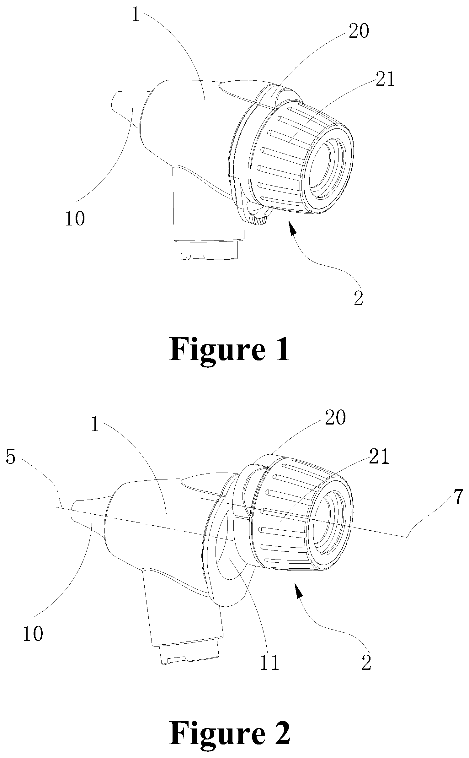
FIG. 1 is a stereograms of the embodiment;
FIG. 2 is a use state diagram of the embodiment;
FIG. 3 is a schematic sectional view of the embodiment;
wherein, 1--otoscope body; 10--tapered portion; 11--inner cavity; 2--observation apparatus; 20--connecting housing; 21--adjusting housing; 22--first optical lens; 23--second optical lens; 3--ear speculum; 4--illuminating apparatus.
DETAILED DESCRIPTION OF EXEMPLARY EMBODIMENTS
In the following, the present disclosure are described in detail combining with the accompanying drawings and embodiments.
A medical otoscope as shown in the figures, comprises an otoscope body 1 and an observation apparatus 2 connected to one end of the otoscope 1, the other end of the otoscope body 1 has a tapered part 10 for inserting into an ear, the otoscope body 1 has a hollow inner cavity 11 communicated with the tapered portion 10, and an ear speculum 3 is detachably mounted on the tapered portion 10.
In the embodiment, the observation apparatus 2 comprises a connecting housing 20 connected to the otoscope body 1 and an adjusting housing 21 connected to the connecting housing 20. When the connecting housing 20 is fixed with respect to the otoscope body 1, the central axis 7 of the observation apparatus 2 can only coaxial with the central axis 5 of the otoscope body 1; when the connecting housing 20 is rotatably connected to the otoscope body 1 via a rotating shaft 8 and the axis 6 of the rotating shaft 8 extends in the same direction as the central axis 5 of the otoscope body 1, rotating the connecting housing 20 may cause the central axis 7 of the entire observation apparatus 2 and the central axis 5 of the otoscope body 1 to be adjusted between being coaxial with or deviating from each other, as shown in FIGS. 1 and 2.
As shown in FIG. 3, the observation apparatus 2 further comprises a first optical lenses 22 and a second optical lens 23 arranged along a same optical axis, wherein, the first optical lenses 22 are consisted of two positive lenses fixedly provided within the connection housing 20, and the second optical lens 23 is a negative lens provided within the adjusting housing 21. In the embodiment, the adjusting housing 21 is rotatably connected to the connecting housing 20, the specific structure may be a thread structure or other conventional adjusting structure, that is, the adjusting housing 21 may be considered to be a rotary knob, and the second optical lens 23 moves with respect to the first optical lens 22 along the optical axis when rotating the adjusting housing 21. This allows the focal length of the optical lens group to be adjusted to achieve the adjustment within the visual field range.
In addition, an illuminating apparatus 4 is provided within the inner cavity 11. When in use, also may rotate the connecting housing 20, such that the central axis 7 of the entire observation apparatus 2 deviates from the central axis 5 of the otoscope body 1, the hollow inner cavity 11 of the otoscope body 1 exposes, and an examination component may also be extended into the ear via the inner cavity 11 for operation during observation via the observation apparatus 2.
The embodiments described above are only for illustrating the technical concepts and features of the present disclosure, and are intended to make those skilled in the art being able to understand the present disclosure and thereby implement it, and should not be concluded to limit the protective scope of this disclosure.
* * * * *
D00000
D00001
D00002
XML
uspto.report is an independent third-party trademark research tool that is not affiliated, endorsed, or sponsored by the United States Patent and Trademark Office (USPTO) or any other governmental organization. The information provided by uspto.report is based on publicly available data at the time of writing and is intended for informational purposes only.
While we strive to provide accurate and up-to-date information, we do not guarantee the accuracy, completeness, reliability, or suitability of the information displayed on this site. The use of this site is at your own risk. Any reliance you place on such information is therefore strictly at your own risk.
All official trademark data, including owner information, should be verified by visiting the official USPTO website at www.uspto.gov. This site is not intended to replace professional legal advice and should not be used as a substitute for consulting with a legal professional who is knowledgeable about trademark law.