Catheter or stent delivery system
Epstein A
U.S. patent number 10,751,206 [Application Number 16/101,670] was granted by the patent office on 2020-08-25 for catheter or stent delivery system. The grantee listed for this patent is Scott M. Epstein. Invention is credited to Scott M. Epstein.


View All Diagrams
| United States Patent | 10,751,206 |
| Epstein | August 25, 2020 |
Catheter or stent delivery system
Abstract
A method for delivering catheters, and stents composed of soft, compliant polymers through anatomical passages. These devices have a bulbous or enlarged anchorage end with a diameter greater than the rest of the catheter. To facilitate implant and delivery a pusher catheter or sheath with an internal lumen larger than the outer diameter of the catheter but smaller than the outer diameter of the bulbous or enlarged anchorage end is provided. The distal end of pusher catheter or the sheath physically engages the proximal end of the bulbous or enlarged anchorage end and applies an axial force to coaxially advance the catheter over a guidewire through anatomical passages. This method allows a physician to move the catheter to an anatomical site without the device exhibiting buckling due to axial force applied. Similarly, this delivery method will allow more force to be applied to the distal end of the catheter diminishing the likelihood of buckling.
| Inventors: | Epstein; Scott M. (Boston, MA) | ||||||||||
|---|---|---|---|---|---|---|---|---|---|---|---|
| Applicant: |
|
||||||||||
| Family ID: | 64459199 | ||||||||||
| Appl. No.: | 16/101,670 | ||||||||||
| Filed: | August 13, 2018 |
Prior Publication Data
| Document Identifier | Publication Date | |
|---|---|---|
| US 20180344493 A1 | Dec 6, 2018 | |
Related U.S. Patent Documents
| Application Number | Filing Date | Patent Number | Issue Date | ||
|---|---|---|---|---|---|
| 14446893 | Jul 30, 2014 | 10568753 | |||
| 12824149 | Jun 26, 2010 | ||||
| Current U.S. Class: | 1/1 |
| Current CPC Class: | A61F 2/848 (20130101); A61F 2/962 (20130101); A61F 2/966 (20130101); A61M 25/01 (20130101); A61M 25/0068 (20130101); A61F 2/04 (20130101); A61F 2230/0039 (20130101); A61M 2025/0293 (20130101); A61F 2002/048 (20130101); A61F 2230/0076 (20130101); A61F 2210/0076 (20130101); A61F 2230/0067 (20130101); A61F 2250/0098 (20130101); A61F 2230/0071 (20130101); A61F 2210/0061 (20130101); A61M 27/008 (20130101); A61M 2025/0681 (20130101); A61F 2/97 (20130101); A61F 2002/8486 (20130101); A61M 25/0021 (20130101); A61F 2250/0039 (20130101) |
| Current International Class: | A61F 2/962 (20130101); A61M 25/00 (20060101); A61F 2/966 (20130101); A61F 2/848 (20130101); A61F 2/04 (20130101); A61M 25/01 (20060101); A61M 25/02 (20060101); A61F 2/97 (20130101); A61M 25/06 (20060101); A61M 27/00 (20060101) |
References Cited [Referenced By]
U.S. Patent Documents
| 3975350 | August 1976 | Hudgin |
| 4026296 | May 1977 | Stoy et al. |
| 4475972 | October 1984 | Wong |
| 4585000 | April 1986 | Hershenson |
| 4610671 | September 1986 | Luther |
| 4762128 | August 1988 | Rosenbluth |
| 4943618 | July 1990 | Stoy et al. |
| 5026366 | June 1991 | Leckrone |
| 5135535 | August 1992 | Kramer |
| 5149052 | September 1992 | Stoy et al. |
| 5405380 | April 1995 | Gianotti et al. |
| 5499975 | March 1996 | Cope et al. |
| 5499994 | March 1996 | Tihon et al. |
| 5601881 | February 1997 | Grimm et al. |
| 5603698 | February 1997 | Roberts |
| 5662703 | September 1997 | Yurek et al. |
| 5697948 | December 1997 | Marin et al. |
| 5785679 | July 1998 | Abolfathi et al. |
| 6027510 | February 2000 | Alt |
| 6039694 | March 2000 | Larson et al. |
| 6143016 | November 2000 | Bleam et al. |
| 6280411 | August 2001 | Lennox |
| 6286785 | September 2001 | Kitchen |
| 6379365 | April 2002 | Diaz |
| 6458156 | October 2002 | Wan et al. |
| 6471684 | October 2002 | Dulak et al. |
| 6488802 | December 2002 | Levingston et al. |
| 6547908 | April 2003 | Keyes et al. |
| 6827731 | December 2004 | Armstrong et al. |
| 6926509 | August 2005 | Nicora et al. |
| 7135015 | November 2006 | Dulak et al. |
| 7316677 | January 2008 | Dulak et al. |
| 7622299 | November 2009 | Sanders et al. |
| 7654989 | February 2010 | Knapp |
| 7655021 | February 2010 | Brasington et al. |
| 7713193 | May 2010 | Nance et al. |
| 8048350 | November 2011 | Epstein |
| 8101196 | January 2012 | Luthra et al. |
| 8235968 | August 2012 | Tremaglio |
| 8282622 | October 2012 | Dulak et al. |
| 8403890 | March 2013 | King et al. |
| 8491620 | July 2013 | Brasington et al. |
| 8597261 | December 2013 | Knapp |
| 8690936 | April 2014 | Nguyen et al. |
| 8696550 | April 2014 | Surti |
| 8708997 | April 2014 | Parker |
| 8709064 | April 2014 | Rasmussen et al. |
| 9180028 | November 2015 | Epstein |
| 2001/0011164 | August 2001 | Bierman |
| 2002/0077592 | June 2002 | Barry |
| 2002/0082549 | June 2002 | Duchamp |
| 2002/0082638 | June 2002 | Porter et al. |
| 2002/0120322 | August 2002 | Thompson et al. |
| 2002/0198440 | December 2002 | Snow |
| 2003/0021762 | January 2003 | Luthra et al. |
| 2003/0040771 | February 2003 | Hyodoh et al. |
| 2003/0109899 | June 2003 | Fisher et al. |
| 2003/0199993 | October 2003 | Gellman et al. |
| 2003/0204238 | October 2003 | Tedeschi |
| 2003/0211130 | November 2003 | Sanders et al. |
| 2003/0216771 | November 2003 | Osypka et al. |
| 2003/0222369 | December 2003 | Nicora et al. |
| 2003/0233117 | December 2003 | Adams et al. |
| 2004/0010284 | January 2004 | Maloof |
| 2004/0015224 | January 2004 | Armstrong |
| 2004/0111143 | June 2004 | Fischell |
| 2004/0143290 | July 2004 | Brightbill |
| 2004/0225346 | November 2004 | Mazumder et al. |
| 2004/0243158 | December 2004 | Konstantino et al. |
| 2005/0038495 | February 2005 | Greenan |
| 2005/0049672 | March 2005 | Murphy |
| 2005/0149160 | July 2005 | McFerran |
| 2005/0182475 | August 2005 | Jen et al. |
| 2005/0033343 | December 2005 | Chermoni |
| 2006/0095066 | May 2006 | Chang et al. |
| 2006/0100664 | May 2006 | Pai et al. |
| 2006/0184226 | August 2006 | Austin |
| 2007/0010786 | January 2007 | Casey et al. |
| 2007/0106361 | May 2007 | Epstein et al. |
| 2007/0208373 | September 2007 | Zaver et al. |
| 2007/0225659 | September 2007 | Melsheimer |
| 2007/0250160 | October 2007 | Rafiee |
| 2007/0299422 | December 2007 | Ignanas et al. |
| 2008/0255603 | October 2008 | Naor |
| 2008/0300629 | December 2008 | Surti |
| 2009/0112050 | April 2009 | Farnan et al. |
| 2009/0299449 | December 2009 | Styrc |
| 2010/0022940 | January 2010 | Thompson |
| 2010/0057122 | March 2010 | Campbell et al. |
| 2011/0153022 | June 2011 | Singhatat et al. |
| 2011/0301689 | December 2011 | Dorn et al. |
| WO0018446 | Apr 2000 | WO | |||
Attorney, Agent or Firm: Intrinsic Law Corp.
Parent Case Text
CROSS-REFERENCE TO RELATED APPLICATIONS
This application is a continuation-in-part of U.S. patent application Ser. No. 14/446,893, titled "Catheter or Stent Delivery System," filed on Jul. 30, 2014, which is a continuation of U.S. patent application Ser. No. 12/824,149, titled "Catheter Delivery System," filed on Jun. 26, 2010.
Claims
What is claimed is:
1. A catheter or stent delivery system comprising: a flexible catheter or stent comprising an elongated cylindrical portion having a catheter shaft length and a catheter shaft diameter, the catheter or stent terminating in an enlarged anchorage portion at a distal end thereof having an anchorage diameter greater than the catheter shaft diameter, said catheter or stent having an internal fluid channel comprising a catheter or stent lumen running through said catheter or stent from a proximal end of the elongated cylindrical portion through the distal end and enlarged anchorage portion; and an elongated pusher tube having an internal lumen running axially therethrough from a proximal to a distal end of the pusher tube, the internal lumen having an internal diameter greater than the catheter shaft diameter but less than the anchorage diameter, the pusher tube; wherein the elongated cylindrical portion of the catheter or stent is disposed within the internal lumen of the pusher tube, and wherein the distal end of the pusher tube physically contacts a proximal end of the enlarged anchorage portion of the catheter or stent, such that an axial force applied to the pusher tube causes the distal end of the pusher tube to transfer said force to said enlarged anchorage portion of the catheter or stent, wherein the delivery system is disposed in a sheath, wherein a distal end of the sheath includes axial slits, wherein the axial slits are configured to open in response to the distal advancement of the enlarged anchorage portion.
2. The delivery system of claim 1, wherein the enlarged anchorage portion has a shape selected from the group consisting of: substantially spherical, substantially ovoid, substantially barbell, substantially trumpet-shaped, and substantially conical.
3. The delivery system of claim 1, wherein the elongated cylindrical portion of the catheter or stent comprises an anchor portion disposed at the proximal end of the elongated cylindrical portion, the anchor portion configured to anchor a proximal end of the catheter or stent in an anatomical cavity.
4. The delivery system of claim 1, wherein port holes are defined in a distal end of the elongated cylindrical portion proximal to the enlarged anchorage.
5. The delivery system of claim 1, wherein the catheter or stent comprises hydrogel polymer layers.
6. A catheter or stent delivery system comprising: a catheter or stent comprising: an elongated cylindrical portion having a first external diameter; and an enlarged anchorage having a second external diameter greater than the first external diameter, the enlarged anchorage disposed at a distal end of the elongated cylindrical portion; a cylindrical pusher tube having a third external diameter less than the second external diameter; an internal channel extending along a channel axis from a proximal end of the cylindrical pusher tube to a distal end of the enlarged anchorage; a sheath having a sheath internal diameter greater than the first and third external diameters but less than the second external diameter, wherein the cylindrical pusher tube and the elongated cylindrical portion are disposed in the sheath such that a distal end of the cylindrical pusher tube physically engages a proximal end of the elongated cylindrical portion, such that an axial force at a proximal end of the cylindrical pusher tube causes the enlarged anchorage to advance distally, wherein the delivery system is disposed in the sheath, wherein a distal end of the sheath includes axial slits, wherein the axial slits are configured to open in response to the distal advancement of the enlarged anchorage.
7. The delivery system of claim 6, wherein the enlarged anchorage has a shape selected from the group consisting of: substantially spherical, substantially ovoid, substantially barbell, substantially trumpet-shaped, and substantially conical.
8. The delivery system of claim 6, wherein the elongated cylindrical portion comprises an anchor portion disposed at the proximal end of the elongated cylindrical portion, the anchor portion configured to anchor a proximal end of the catheter or stent in an anatomical cavity.
9. The delivery system of claim 6, wherein port holes are defined in a distal end of the elongated cylindrical portion proximal to the enlarged anchorage.
10. The delivery system of claim 6, wherein the catheter or stent comprises hydrogel polymer layers.
11. A method for delivering a catheter or stent to a target site through an elongated anatomical lumen, the method comprising: a) inserting a guidewire into a patient, such that a distal end of the guidewire is proximal to the target site and a proximal end of the guidewire is accessible to a user; b) placing an internal channel of the catheter or stent on the proximal end of the guidewire, the catheter or stent comprising: an elongated cylindrical portion having a first diameter; an enlarged anchorage having a second diameter greater than the first diameter, the enlarged anchorage disposed at a distal end of the elongated cylindrical portion; and the internal channel extending along a channel axis from a proximal end of the elongated cylindrical member to a distal end of the enlarged anchorage; c) placing a tubular pusher tube over a proximal end of the catheter or stent, the pusher tube having an internal lumen, the internal lumen having an internal diameter greater than the first diameter but less than the second diameter; d) applying an axial force to a proximal end of the pusher tube, the axial force causing a wall on a distal end of the pusher tube to physically engage a proximal end of the enlarged anchorage, such that the axial force at the proximal end of the pusher tube causes the enlarged anchorage to advance distally along the guidewire, wherein the catheter or stent and pusher tube are disposed in a sheath, wherein a distal end of the sheath includes axial slits, wherein the axial slits are configured to open in response to the distal advancement of the enlarged anchorage.
12. The method of claim 11, further comprising stopping the axial force when the catheter or stent is positioned proximal to the anatomical site.
13. The method of claim 12, further comprising removing the pusher tube after said catheter or stent reach the target site.
14. The method of claim 11, further comprising transferring axial insertion forces from a proximal end of said pusher tube to a distal end of said catheter or stent.
Description
FIELD OF INVENTION
The present invention relates to a catheter delivery method and apparatus for delivering catheters or stents, specifically catheters or stents composed of soft, compliant polymers or other suitable materials, through anatomical passages, vascular networks, lumens and cavities.
BACKGROUND OF INVENTION
Specifically-trained physicians often implant a catheter or stent over a guidewire, proximate to, vascular and non-vascular occlusions; or to maintain patency of an anatomical lumen. To implant these devices, a physician must pass the device through vascular and non-vascular anatomical passages and cavities to reach the intended anatomical site which may exhibit an occlusion or an increased resistance when advancing the catheter or stent to the intended location.
One accepted method for passing these devices through anatomical passages includes placing the distal end (defined as the end that is farthest from the Physician) of a guidewire proximate to the anatomical site and advancing the catheter coaxially over the guidewire. In this method, the catheter is pushed from the proximal (defined as the end closest to the Physician) end of the guidewire to the distal end towards the anatomical site. The catheter is advanced either by hand (squeezing the catheter with an index finger and thumb and pushing along) or by using a relatively rigid plastic tube to push the catheter from behind.
In this method, the catheter must be pushed over the guidewire through long, sometimes tortuous, paths, reductions in lumen diameter and anatomical obstructions. Unfortunately, these obstacles require the physician to push the catheter or stent with increasingly excessive axial forces, and depending on the device design or the material from which the device is fabricated, buckling may occur.
Buckling of the device, due to excessive axial forces, is undesired as it may result in a damaged catheter, patient discomfort, accidental perforation of surrounding anatomy and prevention of catheter implantation to its intended location.
The axial load is the maximum force that may be applied to a catheter or stent when advancing the device into a patient before it begins to buckle. Therefore, the axial load is limited by the column strength of the device. This axial load is characterized by the Euler Equation for a simply supported device column under an external axial load (F); wherein (E=modulus of elasticity of the device; I=is the moment of inertia of the cross section of the device; and L=column length of the device). Accordingly, the buckling load of a catheter or stent can be determined by: F=((E)*(I)(3.14).sup.2)/(L.sup.2)
With respect to the Euler Equation, if Length (L), and Moment of Inertia (I) are constant, only a change in materials with an increase in modulus of Elasticity (E) will increase the axial load capacity of a catheter or stent. For example, using the above Euler Equation, pushing a catheter with a length of (0.5 inches (L=0.50 inch)); compared to a catheter with a length of (12 inches (L=12.0 inch)) exhibits a profound effect on the axial load capacity (F). Considering that (L) is raised to the power of (2); it can be seen that (0.50 inches).sup.2 versus (12 inches).sup.2=0.25 versus 144; or a factor of over 500:1. Thus, devices with shorter columns will have a much greater axial load capacity resisting bucking. Unfortunately, shorter catheters are not practical; nor are they typically used in conventional applications where pushing a catheter is the method of delivery.
Multiple techniques have been developed by physicians to prevent buckling of the catheter during implantation. Many of the techniques mentioned below are often combined to reduce catheter buckling.
One technique is for physicians to apply only small amounts of axial force to the catheter either manually (by hand) or with a plastic tube (pusher catheter). This small axial force results in advancing the catheter several millimeters at a time. While this slow advance of the catheter does provide immediate tactile feedback to the physician should the catheter confront an obstruction during advancement, the process is long and tedious. In addition, once the catheter reaches the vascular occlusion at the implantation site, additional axial forces still must be applied in order to push the catheter across the occlusion. This increased axial force often causes the catheter, especially smaller diameter devices, to buckle.
An additional technique to prevent buckling of a catheter during implantation is to use a catheter or stent that is coated with layers of a lubricous polymer. These lubricous polymer coatings, which are typically are very thin, and relatively fragile, reduce the coefficient of friction of the device, which results in a reduced axial load. When these coated devices are inserted and advanced through anatomical paths, they encounter boundaries, such as vessel walls. These coated devices, which are flexible enough to bend tangentially at these boundaries, continue advancing along the anatomical path; however, these tangential bends may add external pressure to the coating at the points of contact. These external pressure points on the device contribute to the aqueous media being squeezed from the coating, much like squeezing water from a sponge. Ultimately, once the coating is compromised, any further contact between the device and anatomical boundaries at these tangential bends will exhibit an increased level of relative friction, such as dry on dry surfaces that results in increased axial loads required to push or advance the catheter along. In addition, this high friction may result in patient discomfort.
A further technique to prevent buckling of the catheter during implantation is to fabricate whole or portions of catheters and stents from moderate to rigid polymers. Similarly, a given thickness of rigid polymer can be extruded while a softer layer is coaxially extruded over or under the more rigid layer. Additionally, a layer of braiding material, either polymeric and or metallic, may be incorporated into the design of a catheter or stent whereby the braid is deposited or sandwiched between layers of catheter material. While these designs are more effective they result in undesirable and uncomfortable products as well as increased manufacturing costs.
Catheters or stents may also be manufactured with rigid portions, such as rigid proximal ends. These more rigid materials often cause patient discomfort and in many cases result in complications due to their increased ability to perforate surrounding anatomy during implantation.
Conventional delivery methods may also include coaxially placing and advancing soft catheters or stents within hollow rigid sheaths, avoiding the need to develop or design catheters that by themselves exhibit superior handling.
In any case, using a sheath or manufacturing a catheter out of more rigid material or incorporating a layer of braiding material are only attempts to increase the column strength of a catheter or stent whereby axial forces and corresponding push-ability can be maximized.
However, using a more rigid material either as part of the catheter, stent or sheath still results in patent pain and or discomfort.
As mentioned previously, many of the techniques mentioned above are often combined to reduce catheter buckling. For instance, in an attempt to augment conventional sheath-over-catheter delivery methods, catheters may be coaxially braided, a more rigid layer maybe integrated, and/or the device may be coated with layers of lubricous polymer. However, even a combination of these techniques results in patient discomfort, slow advancement and eventual buckling of the catheter or stent when increased axial loads are required to advance into or through anatomical passages.
Therefore, embodiments of the invention establish a novel method for delivery of catheters and stents that overcomes the buckling phenomena.
SUMMARY OF INVENTION
There are additional features of the invention that will be described hereinafter and which will form the subject matter of the claims appended hereto. In this respect, before explaining at least one embodiment of the invention in detail, it is to be understood that the invention is not limited in its application to the details of construction and to the arrangements of the components set forth in the following description or illustrated in the drawings. The invention is capable of other embodiments and of being practiced and carried out in various ways. Also, it is to be understood that the phraseology and terminology employed herein are for the purpose of the description and should not be regarded as limiting.
An aspect of the subject invention discloses a method for delivering a catheter or stent to an anatomical site, the method comprising: a) inserting a guidewire into a patient, such that a distal end of the guidewire is proximal to the anatomical site and a proximal end of the guidewire is accessible to a user; b) placing a catheter with an internal channel with a first opening on the distal end and a second opening on a proximal end over the guidewire such that the guidewire is contained within the internal channel, wherein the proximal end of catheter comprises a first external diameter and the distal end comprises a second external diameter, further wherein the second external diameter is larger than the first external diameter such that the distal end of the catheter comprises a proximal external contacting surface; c) placing a tube, sheath, or Pusher catheter with a distal opening and an internal channel over the proximal end of the catheter, wherein the diameter of the distal opening and the internal channel is larger than the first external diameter, but smaller than the second external diameter, further wherein the tube, sheath, or Pusher catheter comprises a distal contacting surface and a proximal pushing surface; d) pushing the tube, sheath, or Pusher catheter over the catheter until the distal contacting surface of the tube engages the proximal external contacting surface of the catheter; e) applying axial force to the proximal pushing surface of the tube, sheath, or Pusher catheter such that it advances the catheter on the guidewire; f) stopping step e) once the catheter or stent is positioned in the anatomical site; and g) removing the tube, sheath or pusher catheter and leaving the catheter or stent in place.
Another aspect of the subject invention is a catheter delivery system comprising: a catheter with an internal channel with a first opening on the distal end and a second opening on a proximal end, wherein the proximal end of catheter comprises a first external diameter and the distal end comprises a second external diameter, further wherein the second external diameter is larger than the first external diameter such that the distal end of the catheter comprises a proximal external contacting surface; a tube with a distal opening, a distal contacting surface and an internal channel, wherein the diameter of the distal opening and the internal channel is larger than the first external diameter of the catheter, but smaller than the second external diameter; wherein the proximal end of the catheter is place into the distal opening of the tube until the distal contacting surface engages the proximal external contacting surface, further wherein the tube pushes the catheter such that both advance over a guidewire that is inserted into a patient such that a distal end of the guidewire is proximal to an anatomical site.
In one embodiment of the subject invention, the shape of the internal channel of the tube, sheath, or Pusher catheter complements the external shape of the proximal end of the catheter.
In another embodiment of the subject invention, the catheter has a cross-sectional shape that is substantially circular, triangular, square, oval, trapezoidal, hexagonal or octagonal.
In an additional embodiment of the subject invention, the shape of the internal channel of the tube, sheath, or pusher catheter has a cross-sectional shape that is substantially circular, triangular, square, oval, trapezoidal, hexagonal or octagonal.
In a further embodiment of the subject invention, the tube, sheath, or pusher catheter comprises substantially resilient material.
In one embodiment of the subject invention, the distal end of the catheter is a bulbous or enlarged anchorage end.
In another embodiment of the subject invention, the catheter comprises, consists of, or consists essentially of a soft compliant material, such as structural hydrogel.
In one embodiment of the subject invention, the method does not require that the guidewire be hydrophilically coated to exhibit a reduction in forces.
In another embodiment of the subject invention, the catheter has at least one port hole proximal to the distal end.
In an additional embodiment of the subject invention, the distal end of the catheter has a profile that is selected from the group consisting of substantially spherical, substantially oval, substantially barbell, substantially trumpet or substantially conical.
Another aspect of the invention is directed to a catheter or stent delivery system. The catheter or stent delivery system comprises: a catheter or stent comprising: an elongated cylindrical portion having a first diameter; a bulbous or enlarged anchorage having a second diameter greater than the first diameter, the bulbous or enlarged anchorage disposed at a distal end of the elongated cylindrical portion; and an internal channel extending along a channel axis from a proximal end of the elongated cylindrical portion to a distal end of the bulbous or enlarged anchorage. The catheter or stent delivery system also comprises: a pusher tube having an internal lumen, the internal lumen having an internal diameter greater than the first diameter but less than the second diameter. The elongated cylindrical portion is disposed in the internal lumen of the pusher tube, and a wall on a distal end of the pusher tube physically engages a proximal end of the bulbous or enlarged anchorage, such that an axial force at a proximal end of the pusher tube causes the bulbous or enlarged anchorage to advance distally.
In one or more embodiments, the bulbous or enlarged anchorage has a shape selected from the group consisting of: substantially spherical, substantially ovoid, substantially barbell, substantially trumpet-shaped, and substantially conical. In one or more embodiments, the delivery system is disposed in a sheath. In one or more embodiments, a distal end of the sheath includes axial slits. In one or more embodiments, the axial slits are configured to open in response to the distal advancement of the bulbous or enlarged anchorage. In one or more embodiments, the elongated cylindrical portion comprises an anchor portion disposed at the proximal end of the elongated cylindrical portion, the anchor portion configured to anchor a proximal end of the catheter or stent in an anatomical cavity. In one or more embodiments, port holes are defined in a distal end of the elongated cylindrical portion proximal to the bulbous or enlarged anchorage. In one or more embodiments, the catheter or stent comprises hydrogel polymer layers.
Another aspect of the invention is directed to a catheter or stent delivery system. The catheter or stent delivery system comprises: a catheter or stent comprising: an elongated cylindrical portion having a first external diameter; and a bulbous or enlarged anchorage having a second external diameter greater than the first external diameter, the bulbous or enlarged anchorage disposed at a distal end of the elongated cylindrical portion. The catheter or stent delivery system also comprises a cylindrical pusher catheter having a third external diameter less than the second external diameter; an internal channel extending along a channel axis from a proximal end of the cylindrical pusher catheter to a distal end of the bulbous or enlarged anchorage; a sheath having a sheath internal diameter greater than the first and third external diameters but less than the second external diameter. The cylindrical pusher catheter and the elongated cylindrical portion are disposed in the sheath such that a distal end of the cylindrical pusher catheter physically engages a proximal end of the elongated cylindrical portion, such that an axial force at a proximal end of the cylindrical pusher catheter causes the bulbous or enlarged anchorage to advance distally.
In one or more embodiments, the bulbous or enlarged anchorage has a shape selected from the group consisting of: substantially spherical, substantially ovoid, substantially barbell, substantially trumpet-shaped, and substantially conical. In one or more embodiments, a distal end of the sheath includes axial slits. In one or more embodiments, the axial slits are configured to open in response to the distal advancement of the bulbous or enlarged anchorage. In one or more embodiments, the elongated cylindrical portion comprises an anchor portion disposed at the proximal end of the elongated cylindrical portion, the anchor portion configured to anchor a proximal end of the catheter or stent in an anatomical cavity. In one or more embodiments, port holes are defined in a distal end of the elongated cylindrical portion proximal to the bulbous or enlarged anchorage. In one or more embodiments, the catheter or stent comprises hydrogel polymer layers.
Another aspect of the invention is directed to a method for delivering a catheter or stent to an anatomical site. The method comprises: a) inserting a guidewire into a patient, such that a distal end of the guidewire is proximal to the anatomical site and a proximal end of the guidewire is accessible to a user; b) placing an internal channel of the catheter or stent on the proximal end of the guidewire; c) placing a pusher tube over a proximal end of the catheter or stent, the pusher tube having an internal lumen, the internal lumen having an internal diameter greater than the first diameter but less than the second diameter; d) applying an axial force to a proximal end of the pusher tube, the axial force causing a wall on a distal end of the pusher tube to physically engage a proximal end of the bulbous or enlarged anchorage, such that the axial force at the proximal end of the pusher tube causes the bulbous or enlarged anchorage to advance distally along the guidewire. The catheter or stent comprises: an elongated cylindrical portion having a first diameter; a bulbous or enlarged anchorage having a second diameter greater than the first diameter, the bulbous or enlarged anchorage disposed at a distal end of the elongated cylindrical portion; and the internal channel extending along a channel axis from a proximal end of the elongated cylindrical member to a distal end of the bulbous or enlarged anchorage.
In one or more embodiments, the method further comprises stopping the axial force when the catheter or stent is positioned proximal to the anatomical site. In one or more embodiments, the method further comprises removing the pusher tube. In one or more embodiments, the method further comprises disposing the catheter or stent in a sheath.
There has thus been outlined, rather broadly, the more important features of the invention in order that the detailed description thereof that follows may be better understood, and in order that the present contribution to the art may be better appreciated. There are additional features of the invention that will be described hereinafter and which will form the subject matter of the claims appended hereto. These together with other objects of the invention, along with the various features of novelty, which characterize the invention, are pointed out with particularity in the claims annexed to and forming a part of this disclosure.
BRIEF DESCRIPTION OF THE DRAWINGS
Advantages of the present invention will be apparent from the following detailed description of exemplary embodiments thereof, which description should be considered in conjunction with the accompanying drawings, in which:
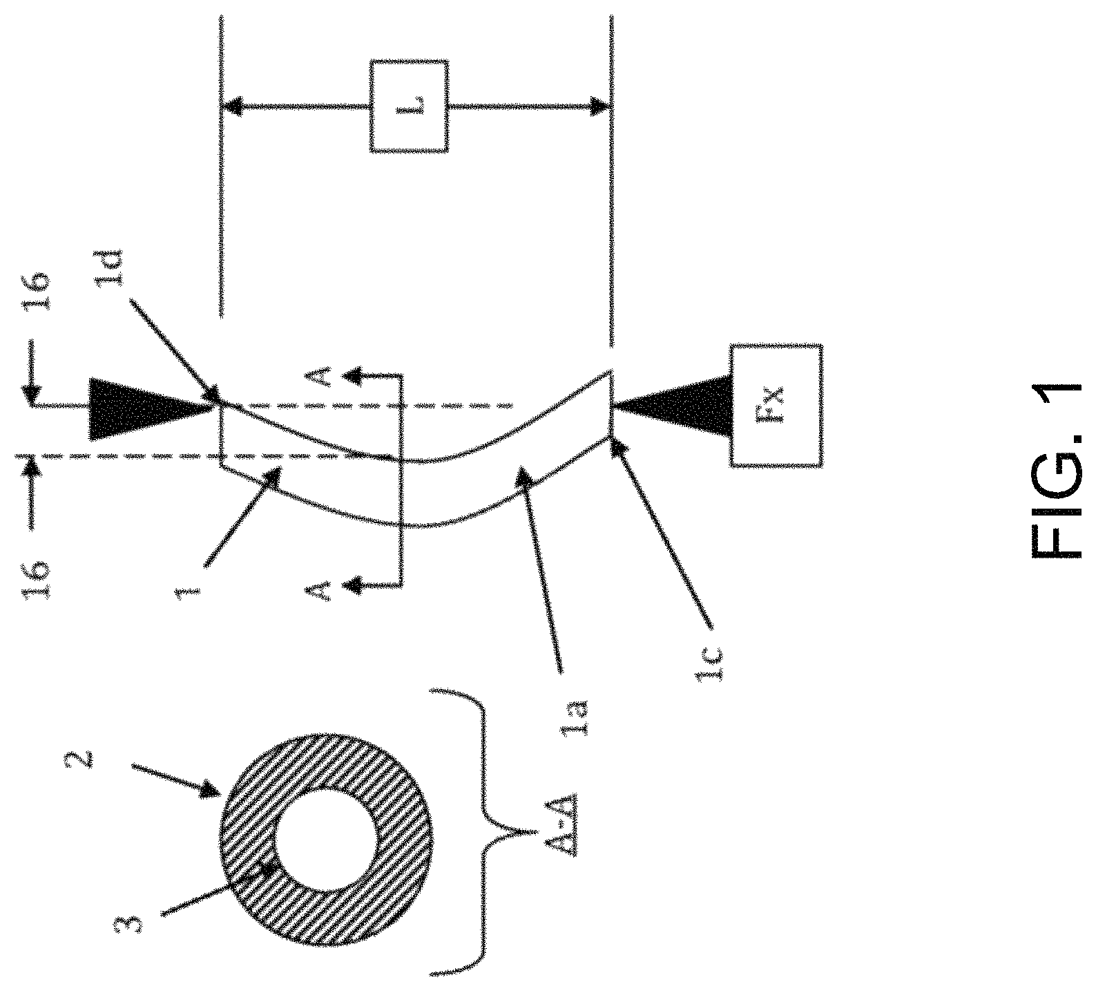
FIG. 1 illustrates a top view and a cross-sectional view of a catheter or stent with simple column catheter shaft with a given length that is subjected to an axial force.
FIG. 2 illustrates a cross-sectional top view of a catheter passing through anatomical lumens upon application of axial force.
FIG. 3 illustrates a top view of a conventional method of implanting a catheter of length.
FIG. 4 illustrates a top cross-sectional view of a catheter with a bulbous or enlarged anchorage end being pushed over a guidewire by the physical engagement of the distal end of a pusher catheter and the proximal end of the bulbous or enlarged anchorage end.
FIG. 5 illustrates a top cross-sectional view of a catheter with a bulbous or enlarged anchorage end being pushed out of a sheath over a guidewire by the physical engagement of the distal end of a pusher catheter and the proximal end of the bulbous or enlarged anchorage end.
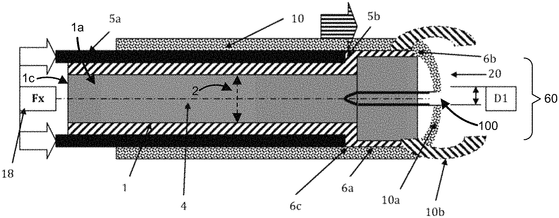
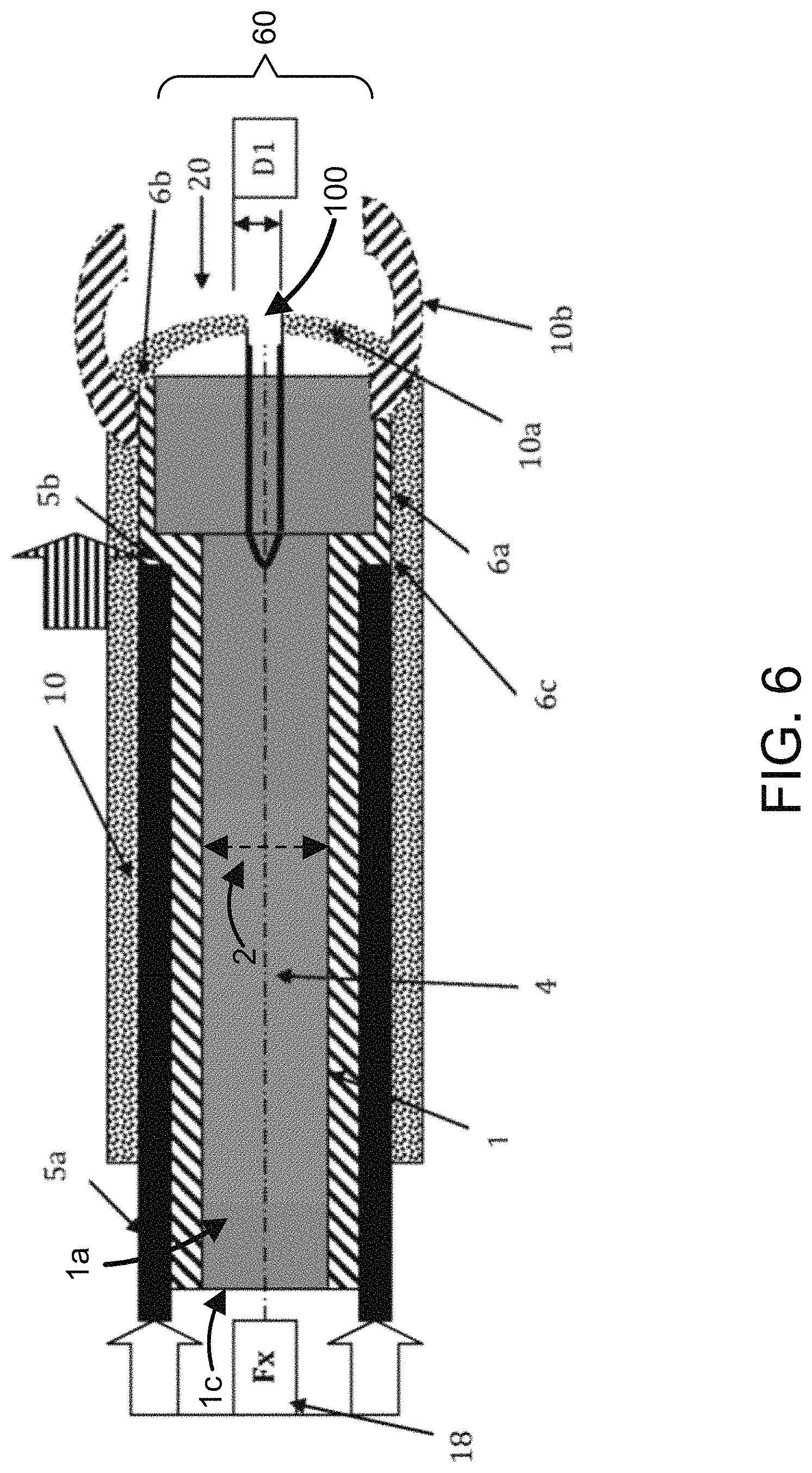
FIG. 6 illustrates a top cross-sectional view of a catheter with a bulbous or enlarged anchorage end and a pusher catheter contained within a sheath that comprises a substantially spherical distal end that remains closed to facilitate advancement through anatomical obstructions, wherein once the desired site is reached, the distal end of a pusher catheter engages the proximal end of the bulbous or enlarged anchorage end to push the catheter out of the distal end of the sheath.
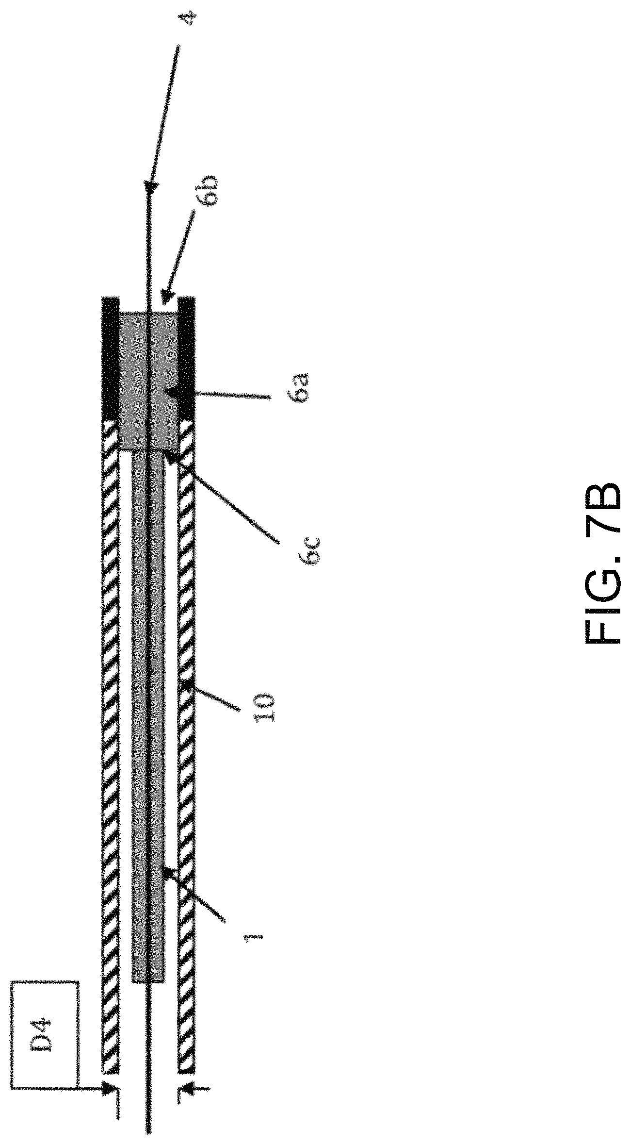
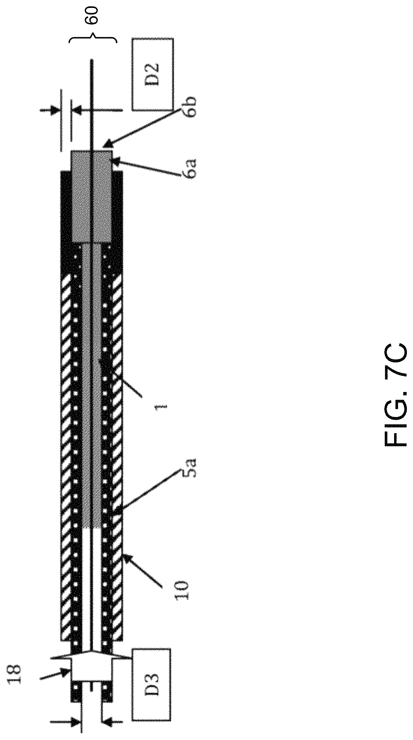
FIGS. 7A, 7B, and 7C illustrate a top cross-sectional view of a catheter with a bulbous or enlarged anchorage end being pushed out of a sheath over a guidewire by the physical engagement of the distal end of a pusher catheter and the proximal end of the bulbous or enlarged anchorage end.
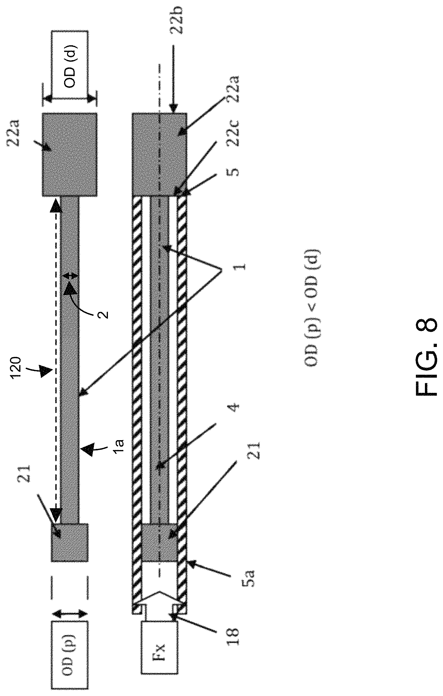
FIG. 8 illustrates a top cross-sectional view of a catheter with a bulbous or enlarged proximal end anchor and a bulbous or enlarged distal end anchor (of larger diameter than the bulbous or enlarged proximal end anchor diameter), being pushed over a guidewire by the physical engagement of the distal end of a pusher catheter and the proximal end of the bulbous or enlarged distal end anchor.
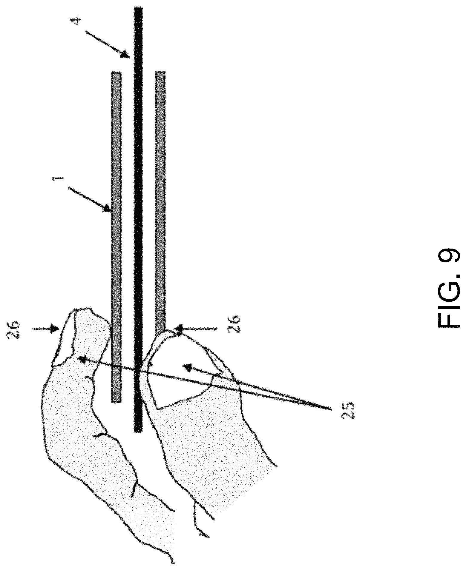
FIG. 9 illustrates a top cross-sectional view of a catheter being pushed by hand over a guidewire.
FIG. 10 illustrates a top view of a conventional pigtail loop catheter and a "J" loop catheter.
FIG. 11 is a flow chart of a method for delivering a catheter or stent to an anatomical site.
DETAILED DESCRIPTION OF PREFERRED EMBODIMENTS
While several variations of the present invention have been illustrated by way of example in particular embodiments, it is apparent that further embodiments could be developed within the spirit and scope of the present invention, or the inventive concept thereof. However, it is to be expressly understood that such modifications and adaptations are within the spirit and scope of the present invention, and are inclusive of, but not limited to, the following appended claims as set forth.
Aspects of the subject invention are directed to a novel method for delivery of catheters and stents to anatomical sites that prevents, or reduces the likelihood of, buckling of the device due to applied axial force. Specifically, for applications where a flexible catheter is made of a soft or pliable material having material properties and having an elongated dimension that would not sustain axial forces to push said soft or pliable flexible catheter into an anatomical lumen to a target site in a patient, this invention provides a pusher tube into which the soft or pliable or flexible catheter or stent is placed. The soft, pliable and flexible catheter is provided with an enlarged or bulbous terminal end at a distant end thereof (the end inserted into the patient). A distal end of the pusher tube being in contact with the enlarged terminus of the flexible catheter or stent, so that the pusher tube can be used to exert axial force directly onto the enlarged terminus of the flexible catheter or stent and to push the catheter or stent into the patient against the force of friction (from the walls of the patient's lumen) and overcoming the buckling forces that would otherwise frustrate the pushing of the flexible (floppy) catheter or stent into such patient lumen space, especially over longer distances or depths. Specifically, if the flexible catheter or stent has a geometry and elongated form factor such that given its material properties it would buckle under the Euler formula and forces described above, the pusher tube would transfer the user's axial pushing force from the proximal end of the system into the distal end of the system, in effect applying said axial inward pushing force at the distal (deep) end of the flexible catheter or stent rather than at its exposed (proximal) end, thereby avoiding or reducing its tendency to buckle.
FIG. 1 is a diagram illustrating a top view and a cross-sectional view of a catheter or stent (1) with simple column catheter shaft (1a) with a given length (L). An axial force (Fx) may be applied to either the proximal end (1c) of catheter (1) by a physician, the distal end (1d) by an anatomical obstruction, or both when the physician continues to push the catheter (1) once it encounters an anatomical obstruction. As shown in FIG. 2, catheter (1) passes through anatomical lumens (7) upon application of axial force (Fx) to the proximal end of the catheter.
During this passage, the catheter (1) may often contact a wall or peripheral structure (8) of lumen (7) or an obstruction (9). Once this contact occurs, a resulting force (Fy) may be applied to the catheter (1) at tangent points, requiring the application of additional axial force (Fx) to continue advancing the catheter (1) to its intended location.
As shown in FIGS. 1 and 2, the axial force Fx applied to catheter (1) is greater than the axial load, causing the catheter to buckle. Lines (16) illustrate the original position of catheter shaft (1a) prior to buckling.
FIG. 1 further illustrates a cross-sectional view of catheter shaft (1a) delineated by line A-A. Catheter shaft (1a) comprises an outer diameter (2) and an inner diameter (3). Diameters (2) and (3) are used to calculate Moment of Inertia (I) for the Euler Equation.
FIG. 9 illustrates a method of implanting a catheter (1) by squeezing (26) the catheter (1) with a hand (25) and manually advancing the catheter (1) over a guidewire (4) by applying an axial force to coaxially advance the catheter over the guidewire (4) in a distal direction through anatomical passages (not shown).
FIG. 3 illustrates a conventional method of implanting a catheter (1) of length (L1). Catheter (1) is coaxially slid over a guidewire (4). A distal end (5b) of a pusher catheter (5a) physically engages the proximal end (1c) of the catheter (1) and applies an axial force (Fx) to coaxially advance the catheter over the guidewire (4) in a distal direction (18) through anatomical passages (not shown).
In this conventional method, pusher catheter (5a) has an internal lumen (not shown) with an internal diameter that is large enough to allow the guidewire (4) to pass through pusher catheter (5a) as it advances; however, this internal lumen diameter is smaller than outer diameter (2) (e.g., as illustrated in FIG. 1) of catheter (1) to allow the distal end (5b) of pusher catheter (5a) to engage the proximal end (1c) of the catheter (1).
FIG. 3 further illustrates two catheter port holes (15) located proximal to the distal end of the catheter (1). These port holes (15) in conventional catheters are designed to increase fluid transfer within the catheter. However, these port holes (15) often result in increased likelihood of buckling, as shown as the likely buckling point (17).
FIG. 4 illustrates an embodiment of a method of the subject invention. A catheter or stent (1) is coaxially slid over the guidewire (4). In this embodiment, the catheter (1) has a bulbous or enlarged anchorage end (6a). The bulbous or enlarged anchorage end (6a) has a distal end (6b) and a proximal end (6c) separated by a length (L2). The bulbous or enlarged anchorage end (6a) has an outer diameter that is greater than the outer diameter (2) of the shaft (1a) of catheter (1). The outer diameter (60) of the bulbous or enlarged anchorage end (6a) is uniform or substantially uniform across the distal end (6b) to the proximal end (6c) of the bulbous or enlarged anchorage end (6a) in the embodiment illustrated in FIG. 4 (e.g., the bulbous or enlarged anchorage end (6a) can have a cylindrical shape defined by its outer diameter and its length (L2)). For example, the outer diameter (60) of the bulbous or enlarged anchorage end (6a), from the distal end (6b) to the proximal end (6c), can be equal to or substantially equal to the outer diameter (50) of the pusher catheter (5a) (e.g., as illustrated in FIG. 4). In other embodiments, the outer diameter (60) of the bulbous or enlarged anchorage end (6a), from the distal end (6b) to the proximal end (6c), can be greater than the outer diameter (50) of the pusher catheter (5a). For example, the bulbous or enlarged anchorage end (6a) can have a uniform or a substantially uniform outer diameter (60), from the distal end (6b) to the proximal end (6c), that is greater than the outer diameter (50) of the pusher catheter (5a). In another example, the outer diameter (60) of the bulbous or enlarged anchorage end (6a) can be greater than the outer diameter (50) of the pusher catheter (5a), but the outer diameter (60) of the bulbous or enlarged anchorage end (6a) can be variable between the distal end (6b) and the proximal end (6c).
In this embodiment, the pusher catheter (5a) has an internal lumen (not shown) with an internal diameter (19) that is large enough to allow the guidewire (4) and the outer diameter (2) of the shaft (1a) of catheter (1) to pass through pusher catheter (5a) as it advances. However, this internal lumen diameter is smaller than the outer diameter (60) of the bulbous or enlarged anchorage end (6a) of catheter (1). Thus, the distal end (5b) of pusher catheter (5a) physically engages the proximal end (6c) of the bulbous or enlarged anchorage end (6a) and applies an axial force (Fx) to coaxially advance the catheter (1) over the guidewire (4) in a distal direction (18) through anatomical passages (not shown). In this manner only a short column length (L2) of the bulbous or enlarged anchorage end (6a) of catheter (1) has an axial load applied to it, a critical variable in column strength analysis. By only applying axial force (Fx) to the proximal end (6c) of the bulbous or enlarged anchorage end (6a), the effective column length of the catheter (1) is reduced to the short column length (L2) of the bulbous or enlarged anchorage end (6a) of catheter (1).
This physical engagement between the distal end (5b) of pusher catheter (5a) and the proximal end (6c) of the bulbous or enlarged anchorage end (6a) diminishes the likelihood of buckling compared to a similar axial force applied to the proximal end (1c) as shown in FIG. 3. Since this method allows the application of additional axial force without buckling, a physician may push catheter (1) through an obstruction. Accordingly, the disclosed delivery method is a universal system which can be used on any catheter or stent with a distal end that has a diameter greater than the shaft diameter of the device. This system diminishes the need for thicker, more rigid catheters. Furthermore, the disclosed invention improves the implantation of catheters and stents comprised of sufficiently soft durometer materials or catheters and stents with ratios of inner diameters and outer diameters that diminish catheter column strength.
This method allows a physician to move the catheter to an anatomical site with less applied axial force over a guidewire since the catheter has less resistance. This method allows a physician to push a relatively short length of catheter rather than a long length. This delivery method will allow more force to be applied to the short distal end of the catheter while diminishing the likelihood of buckling.
In one embodiment of the subject invention, the catheter (1) may have port holes, similar to those shown in FIG. 3, on the shaft (1a) immediately proximal (not shown) to the bulbous or enlarged anchorage end (6a) that do not affect buckling of the device. In this embodiment, the internal lumen of the pusher catheter (5a) will pass over the port holes contained on the outer diameter (2) of the shaft (1a) of catheter (1) to physically engage the proximal end (6c) of the bulbous or enlarged anchorage end (6a).
FIG. 5 illustrates another embodiment of a method of the subject invention. In this embodiment, a catheter or stent (1) is coaxially slid over the guidewire (4). The catheter (1) has a bulbous or enlarged anchorage end (6a) in the shape of a sphere or other suitable shape defined by the outer diameter (60) of the bulbous or enlarged anchorage end (6a). The bulbous or enlarged anchorage end (6a) has a distal end (6b) and a proximal end (6c) separated by a length (L2). The outer diameter (60) of the bulbous or enlarged anchorage end (6a) is greater than outer diameter (2) of the shaft (1a) of the catheter (1) such that a distal end (20) of sheath (10) can physically engage the proximal end (6c) of the bulbous or enlarged anchorage end (6a). As shown, the outer diameter (2) of the shaft (1a) of the catheter (1) is contained within a sheath (10) and the bulbous or enlarged anchorage end (6a) is not contained within the sheath (10). To facilitate delivery of the catheter (1) through anatomical obstructions (illustrated by lumen (7) surrounded by walls (8)), the outer diameter (2) of the shaft (1a) and bulbous or enlarged anchorage end (6a) of the catheter (1) are both initially contained within sheath (10) (not shown). Once the anatomical site is reached, a distal end (20) of sheath (10) physically engages the proximal end (6c) of the bulbous or enlarged anchorage end (6a) while within the sheath (10) and applies an axial force (Fx) to coaxially advance the catheter (1) over the guidewire (4) in a distal direction (18) to push the catheter (1) out of the distal end (20) of the sheath (10) into lumen (7). The pusher catheter (5a) has an internal lumen (not shown) with an internal diameter (19) that is large enough to allow the guidewire (4) to pass through pusher catheter (5a) as it advances. In another embodiment of the subject invention, distal end (5b) of pusher catheter (5a) may also physically engage the proximal end (1c) of the catheter (1) and apply an axial force (Fx) to coaxially advance the catheter (1) over the guidewire (4) out through the distal end (20) of sheath (10) once the anatomical site is reached.
FIG. 6 illustrates an alternative embodiment of a method of the subject invention. In this embodiment, a catheter or stent (1) has a bulbous or enlarged anchorage end (6a) with a distal end (6b) and a proximal end (6c). The bulbous or enlarged anchorage end (6a) has an outer diameter that is greater than outer diameter (2) of the shaft (1a) of catheter (1). A pusher catheter (5a) has an internal lumen (not shown) with an internal diameter that is large enough to allow the outer diameter (2) of the shaft (1a) of catheter (1) to pass through pusher catheter (5a) as it advances. However, this internal lumen diameter is smaller than the outer diameter (60) of the bulbous or enlarged anchorage end (6a) of catheter (1). Thus, the distal end (5b) of pusher catheter (5a) physically engages the proximal end (6c) of the bulbous or enlarged anchorage end (6a). The shaft (1a) of catheter (1) and the bulbous or enlarged anchorage end (6a) are both coaxially slid and contained within sheath (10). Sheath (10) has a closed end (10a) with axial slits (100) of a corresponding thickness (D1). The catheter (1), the pusher catheter (5a) and the sheath (10) are all coaxially slid over a guidewire (4). The distal end (5b) of pusher catheter (5a) physically engages the proximal end (6c) of the bulbous or enlarged anchorage end (6a) and applies an axial force (Fx) to coaxially advance the catheter (1) and the sheath (10) over the guidewire (4) in a distal direction (18). Once the anatomical site is reached, the distal end (5b) of pusher catheter (5a) physically engages the proximal end (1c) of the catheter (1) and applies an axial force (Fx) to coaxially advance the catheter (1) over the guidewire (4) out through sheath (10). The axial slits open (10b) to allow catheter or stent (1) to coaxially slide over the guidewire (4) and through sheath (10). A pusher catheter (5a) within a sheath (10) with a closed end adds greater stability when pushing the catheter through difficult and occluded passages.
FIGS. 7A-C illustrate another embodiment of a method of the subject invention. A catheter or stent (1) is loaded or facilitated into a sheath (10) thru a loading fixture (12). A loading fixture (12) contains a lumen (23) with distal and proximal openings. The proximal opening of loading fixture (12) has an internal diameter that is greater than the external diameter of sheath (10).
The distal end of sheath (10) is inserted in the proximal opening of loading fixture (12). The proximal end of catheter (1) is then inserted into the distal opening of loading fixture (12) by applying an axial force (24) to the distal end (6b) of the bulbous or enlarged anchorage end (6a). Catheter (1) passes through the internal lumen of fixture (12) and inserts into in internal diameter (D4) of sheath (10) until the bulbous or enlarged anchorage end (6a) (collapses and) is fully contained within sheath (10). A pusher catheter (5a) has an internal lumen (not shown) in inserted into the proximal end of sheath (10). Pusher catheter (5a) has an internal diameter (D3) that is large enough to allow the outer diameter (2) of the shaft (1a) of catheter (1) to pass through pusher catheter (5a) as it advances. However, this internal lumen diameter is smaller than the outer diameter (60) of the bulbous or enlarged anchorage end (6a) of catheter (1). Thus, the distal end (5b) of pusher catheter (5a) physically engages the proximal end (6c) of the bulbous or enlarged anchorage end (6a). The catheter (1) and the bulbous or enlarged anchorage end (6a) are both coaxially contained within sheath (10). Once the anatomical site is reached, the distal end (5b) of pusher catheter (5a) physically engages the proximal end (6c) of the bulbous or enlarged anchorage end (6a) and applies an axial force (Fx) to coaxially advance the catheter (1) over the guidewire (4) in a distal direction (18) out through sheath (10).
FIG. 8 illustrates a top cross-sectional view of a catheter (1) with a bulbous or enlarged proximal end anchor (21) with an outer diameter (OD (p)) and a bulbous or enlarged distal end anchor (22a) with an outer diameter (OD (d)). The distance between bulbous or enlarged proximal end anchor (21) and the bulbous or enlarged distal end anchor (22a) has a length (120) along shaft (1a) of the catheter (1). The outer diameter (OD (p)) is slightly smaller that outer diameter (OD (d)), which are both larger than the outer diameter (2) of the shaft (1a) of the catheter (1). The bulbous or enlarged distal end anchor (22a) has a distal end (22b) and a proximal end (22c).
A pusher catheter (5a) has an internal lumen (not shown) with an internal diameter that is large enough to allow the guidewire (4), the outer diameter (2) and the outer diameter (OD (p)) of the bulbous or enlarged proximal end anchor to pass through pusher catheter (5a) as it advances. However, this internal lumen diameter is smaller than the outer diameter OD (d) of the bulbous or enlarged distal end anchor (22a) of catheter (1). Thus, the distal end (5b) of pusher catheter (5a) physically engages the proximal end (22c) of the bulbous or enlarged distal end anchor (22a) and applies an axial force (Fx) to coaxially advance the catheter (1) over the guidewire (4) in a distal direction (18) through anatomical passages (not shown).
As shown in FIG. 10, Ureteral stents often have this type of proximal and distal anchorage ends. However, conventional Ureteral stents typically have an end with a spiral or "pigtail" loop (27) configuration, or a "J" shaped loop (28) configuration.
This method of delivery will reduce the pain and discomfort in patients caused by the deformation of Pigtail loop (27) and J shaped loop (28) during catheter implantation. This pain is partially due to the winding and unwinding of the pigtail loop (27) or J shaped loop (28) during implantation. Unfortunately, as these loops unwind to about half the circumference of the loop diameter, the loops become stuck in that configuration. Thereafter, the radial forces which project from the re-configured loops subject the patient to pain, and discomfort.
FIG. 11 is a flow chart 1100 of a method for delivering a catheter or stent to an anatomical site. In step 1110, a guidewire is inserted into a patient, such that a distal end of the guidewire is proximal to the anatomical site and a proximal end of the guidewire is accessible to a user. In step 1120, an internal channel of the catheter or stent is placed on the proximal end of the guidewire. The catheter or stent comprises an elongated cylindrical portion having a first diameter; a bulbous or enlarged anchorage having a second diameter greater than the first diameter, the bulbous or enlarged anchorage disposed at a distal end of the elongated cylindrical portion; and the internal channel extending along a channel axis from a proximal end of the elongated cylindrical member to a distal end of the bulbous or enlarged anchorage. In step 1130, a pusher tube is placed over a proximal end of the catheter or stent, the pusher tube having an internal lumen, the internal lumen having an internal diameter greater than the first diameter but less than the second diameter. In step 1140, an axial force to a proximal end of the pusher tube is applied, the axial force causing a wall on a distal end of the pusher tube to physically engage a proximal end of the bulbous or enlarged anchorage. In step 1150, the axial force at the proximal end of the pusher tube causes the bulbous or enlarged anchorage to advance distally along the guidewire.
In various embodiments of the subject invention, the sheath or pusher catheter may have radiopaque ends.
In other embodiments of the subject invention, the bulbous or enlarged anchorage end of the catheter or stent may have a spherical, oval, barbell, trumpet or conical profile.
In another embodiment of the subject invention, the stent or catheter used in the method may be composed entirely or partially of soft hydrogel polymer layers, such as the soft hydrogel ureteral stents disclosed in Epstein, U.S. Published Patent Application No. 2007/0106361. The contents of Epstein are incorporated herein by reference.
The devices disclosed in Epstein are composed entirely of, or have integral components, such as the bulbous or enlarged anchorage end, composed entirely of 100% hydrogel layers. Thus, the devices can comprise, consists of, or consist essentially of hydrogel layers. The hydrogel is an integral component comprising the stent or catheter, not a coating that may erode during passage through anatomical lumens.
These hydrogel devices may also be implanted with a substantially smaller diameter that is partially or totally dehydrated. In this manner, the ratio of proximal to distal diameters is typical to the fully hydrated devices whereby a pusher catheter may still coaxially slide over the proximal end diameter and engage a slightly larger distal end diameter. Upon reaching the anatomical site, these highly hydrophilic devices are then hydrated with a significant volume of an aqueous media, such as saline. Upon hydration, the hydrogel cross sections of these devices expand into predictable larger, soft, easily compressible and structurally stable shapes that maintain their mechanical integrity.
These devices do not erode and do not require a substrate or scaffold to maintain their composition or mechanical characteristics. Substantial mechanical characteristics are exhibited by fully hydrated devices, which can be loaded with colorants, radiopacifiers and fillers. These devices immediately exhibit lubricous surface characteristics when wetted with any aqueous media and provide increased resistance to biological complications, such as physiological rejection or inflammation, once implanted. The anchorage ends of these devices will not migrate will exhibit resistance to encrustation and will facilitate the ease of implant and withdrawal.
Furthermore, hybrid designs utilizing a hydrogel component and non-hydrogel components can be engineered with different percent concentrations of solids in a specific layer, or positioned specifically along the axis of a catheter shaft. In this manner, radiopaque media can be placed where it is desired, or a denser matrix can be produced in specific layers along the axis, providing a differential gradient that promotes diffusion or conduction enhancing drainage, or providing a specific drug delivery barrier.
In another embodiment of the subject invention, a low profile balloon may be integrated into the catheter, either within or external to the bulbous or enlarged anchorage end.
* * * * *
D00000
D00001
D00002
D00003
D00004
D00005
D00006
D00007
D00008
D00009
D00010
D00011
D00012

D00013

XML
uspto.report is an independent third-party trademark research tool that is not affiliated, endorsed, or sponsored by the United States Patent and Trademark Office (USPTO) or any other governmental organization. The information provided by uspto.report is based on publicly available data at the time of writing and is intended for informational purposes only.
While we strive to provide accurate and up-to-date information, we do not guarantee the accuracy, completeness, reliability, or suitability of the information displayed on this site. The use of this site is at your own risk. Any reliance you place on such information is therefore strictly at your own risk.
All official trademark data, including owner information, should be verified by visiting the official USPTO website at www.uspto.gov. This site is not intended to replace professional legal advice and should not be used as a substitute for consulting with a legal professional who is knowledgeable about trademark law.