System and method for monitoring devices relative to a user defined geographic area
Chen , et al. A
U.S. patent number 10,750,312 [Application Number 15/696,950] was granted by the patent office on 2020-08-18 for system and method for monitoring devices relative to a user defined geographic area. This patent grant is currently assigned to Aeris Communications, Inc.. The grantee listed for this patent is Aeris Communications, Inc.. Invention is credited to Santosh Astagi, Yixiang Chen, Drew S. Johnson, Fumito Kayama.


View All Diagrams
| United States Patent | 10,750,312 |
| Chen , et al. | August 18, 2020 |
System and method for monitoring devices relative to a user defined geographic area
Abstract
The present invention relates generally to providing a system and method for monitoring devices relative to a user defined geographic area using an enablement platform for building web sites and web applications using data storage, management and publication capabilities of hosted web services. The system and method for monitoring M2M devices relative to a user defined geographic area (geofence) are built on existing AerCloud concepts by allowing user to define location attributes and by using the user defined location attributes to configure and evaluate geofence parameters and issue alerts if the devices are performing outside the geofence parameters.
| Inventors: | Chen; Yixiang (Palo Alto, CA), Kayama; Fumito (Pacifica, CA), Astagi; Santosh (San Mateo, CA), Johnson; Drew S. (San Jose, CA) | ||||||||||
|---|---|---|---|---|---|---|---|---|---|---|---|
| Applicant: |
|
||||||||||
| Assignee: | Aeris Communications, Inc. (San
Jose, CA) |
||||||||||
| Family ID: | 57994506 | ||||||||||
| Appl. No.: | 15/696,950 | ||||||||||
| Filed: | September 6, 2017 |
Prior Publication Data
| Document Identifier | Publication Date | |
|---|---|---|
| US 20170366933 A1 | Dec 21, 2017 | |
Related U.S. Patent Documents
| Application Number | Filing Date | Patent Number | Issue Date | ||
|---|---|---|---|---|---|
| 15234463 | Aug 11, 2016 | 9774994 | |||
| 62205639 | Aug 14, 2015 | ||||
| Current U.S. Class: | 1/1 |
| Current CPC Class: | H04W 4/021 (20130101); H04L 67/02 (20130101); H04W 4/70 (20180201) |
| Current International Class: | H04W 4/021 (20180101); H04L 29/08 (20060101); H04W 4/70 (20180101) |
| Field of Search: | ;455/404.2,412.1-414.2,418-422.1,41.1-41.2,552.1,556.1,456.1-456.3,456.5-457 |
References Cited [Referenced By]
U.S. Patent Documents
| 6239707 | May 2001 | Park |
| 6496775 | December 2002 | McDonald, Jr. |
| 6651001 | November 2003 | Apsell |
| 6687356 | February 2004 | Glitho |
| 6931309 | August 2005 | Phelan |
| 7213048 | May 2007 | Parupudi |
| 7246009 | July 2007 | Hamblen |
| 7801538 | September 2010 | Weiser |
| 7848765 | December 2010 | Phillips |
| 8000726 | August 2011 | Altman |
| 8018329 | September 2011 | Morgan |
| 8135505 | March 2012 | Vengroff |
| 8346230 | January 2013 | Goodman |
| 8473148 | June 2013 | Nielsen |
| 8510200 | August 2013 | Pearlman |
| 8566014 | October 2013 | Kozolchyk |
| 8589330 | November 2013 | Petersen |
| 8593277 | November 2013 | Nath |
| 8595696 | November 2013 | Maximilien et al. |
| 8630768 | January 2014 | McClellan |
| 8667456 | March 2014 | Czymontek |
| 8725569 | May 2014 | Liang |
| 8755824 | June 2014 | Wang |
| 8756010 | June 2014 | Gupta |
| 8869038 | October 2014 | Eick |
| 8909256 | December 2014 | Fraccaroli |
| 8913983 | December 2014 | Lorello |
| 8949022 | February 2015 | Fahrner |
| 8971930 | March 2015 | Li |
| 9014888 | April 2015 | Sukkarie |
| 9043222 | May 2015 | Kerr |
| 9076009 | July 2015 | Sathish |
| 9076165 | July 2015 | Busch |
| 9104738 | August 2015 | Kay et al. |
| 9119038 | August 2015 | Woods |
| 9122693 | September 2015 | Blom |
| 9140567 | September 2015 | Fryer |
| 9141266 | September 2015 | McCormick |
| 9146721 | September 2015 | Nagaraja |
| 9210534 | December 2015 | Matthieu |
| 9225519 | December 2015 | Fraccaroli |
| 9250887 | February 2016 | Lucovsky |
| 9275114 | March 2016 | Milton |
| 9277362 | March 2016 | Li |
| 9349128 | May 2016 | Kerr |
| 9424751 | August 2016 | Hodges |
| 9507346 | November 2016 | Levinson |
| 9576295 | February 2017 | Volpe |
| 9615202 | April 2017 | Dal Santo |
| 9661470 | May 2017 | Du Bois |
| 9712486 | July 2017 | Johnson |
| 9712972 | July 2017 | Lynch |
| 9741191 | August 2017 | Wong |
| 9774994 | September 2017 | Chen |
| 9792567 | October 2017 | Khasis |
| 9805521 | October 2017 | Davidson |
| 9817948 | November 2017 | Swank |
| 9826345 | November 2017 | Haro |
| 9838843 | December 2017 | Bajaj |
| 9871865 | January 2018 | Shaashua |
| 9878663 | January 2018 | Kochura |
| 9988058 | June 2018 | Phillips |
| 10037668 | July 2018 | DesGarennes |
| 10097960 | October 2018 | Tung |
| 10231084 | March 2019 | Bagchi |
| 2004/0111195 | June 2004 | Vries |
| 2004/0193617 | September 2004 | Adler |
| 2005/0090978 | April 2005 | Bathory |
| 2005/0096009 | May 2005 | Ackley |
| 2005/0156715 | July 2005 | Zou |
| 2006/0248121 | November 2006 | Cacenco et al. |
| 2007/0143013 | June 2007 | Breen |
| 2007/0173991 | July 2007 | Tenzer |
| 2008/0033791 | February 2008 | Jones |
| 2008/0125965 | May 2008 | Carani |
| 2008/0319602 | December 2008 | McClellan |
| 2009/0009321 | January 2009 | McClellan |
| 2009/0079555 | March 2009 | Aguirre De Carcerlonio |
| 2009/0248883 | October 2009 | Suryanarayana |
| 2009/0019357 | November 2009 | Cudich |
| 2009/0275348 | November 2009 | Weinreich |
| 2009/0309789 | December 2009 | Verechtchiagine |
| 2009/0326991 | December 2009 | Wei |
| 2010/0075648 | March 2010 | Matsuoka |
| 2010/0094500 | April 2010 | Jin |
| 2010/0106603 | April 2010 | Dey |
| 2010/0203901 | August 2010 | Dinoff |
| 2010/0214068 | August 2010 | Nadkarni |
| 2010/0280734 | November 2010 | Brinton |
| 2010/0289644 | November 2010 | Slavin |
| 2010/0306735 | December 2010 | Hoff et al. |
| 2011/0112768 | May 2011 | Doyle |
| 2011/0126168 | May 2011 | Ilyayev |
| 2011/0178811 | July 2011 | Sheridan |
| 2011/0202591 | August 2011 | Reis |
| 2011/0238457 | September 2011 | Mason |
| 2012/0058764 | March 2012 | Kang |
| 2012/0260228 | October 2012 | Mallick |
| 2012/0330722 | December 2012 | Volpe et al. |
| 2013/0031029 | January 2013 | Davidson |
| 2013/0055253 | February 2013 | Jubran |
| 2013/0066688 | March 2013 | Pinkus |
| 2013/0090106 | April 2013 | Mathews |
| 2013/0093603 | April 2013 | Tschirhart |
| 2013/0103307 | April 2013 | Sartipi |
| 2013/0190967 | July 2013 | Hassib |
| 2013/0212130 | August 2013 | Rahnama |
| 2013/0245880 | September 2013 | McQuade |
| 2013/0254755 | September 2013 | Yousouf |
| 2013/0267253 | October 2013 | Case |
| 2013/0289819 | October 2013 | Hassib |
| 2013/0289873 | October 2013 | Mitchell |
| 2013/0297803 | November 2013 | Hate |
| 2013/0304347 | November 2013 | Davidson |
| 2013/0340305 | December 2013 | Mobley |
| 2013/0346336 | December 2013 | Murphy |
| 2014/0026113 | January 2014 | Farooqi |
| 2014/0031073 | January 2014 | Davis |
| 2014/0057648 | February 2014 | Lyman |
| 2014/0059695 | February 2014 | Parecki |
| 2014/0062695 | March 2014 | Rosen |
| 2014/0095214 | April 2014 | Mathe et al. |
| 2014/0155094 | June 2014 | Zises |
| 2014/0172294 | June 2014 | Kalra |
| 2014/0215043 | July 2014 | Ryu et al. |
| 2014/0226470 | August 2014 | Kim |
| 2014/0274115 | September 2014 | Michalson |
| 2014/0274136 | September 2014 | Edge |
| 2014/0282380 | September 2014 | Abrahams |
| 2014/0325048 | October 2014 | Benchorin |
| 2014/0325394 | October 2014 | Hamill |
| 2014/0351411 | November 2014 | Woods |
| 2014/0359552 | December 2014 | Misra |
| 2014/0370911 | December 2014 | Gorgenyi |
| 2014/0380264 | December 2014 | Misra et al. |
| 2015/0012908 | January 2015 | Farooqi |
| 2015/0095355 | April 2015 | Patton |
| 2015/0106206 | April 2015 | Vengroff |
| 2015/0135163 | May 2015 | Mun |
| 2015/0149980 | May 2015 | Zhong |
| 2015/0163626 | June 2015 | Zimmer |
| 2015/0163630 | June 2015 | Hughes, Jr. |
| 2015/0173037 | June 2015 | Pijl |
| 2015/0180746 | June 2015 | Day, II |
| 2015/0181016 | June 2015 | Jain |
| 2015/0245189 | August 2015 | Nalluri |
| 2015/0264527 | September 2015 | Wang |
| 2015/0271033 | September 2015 | Srivastava et al. |
| 2015/0278759 | October 2015 | Harris |
| 2015/0304175 | October 2015 | Maes |
| 2015/0350843 | December 2015 | Jensen et al. |
| 2016/0003627 | January 2016 | Bonhomme |
| 2016/0041833 | February 2016 | Standley et al. |
| 2016/0042303 | February 2016 | Medina |
| 2016/0050536 | February 2016 | You |
| 2016/0057209 | February 2016 | Parikh |
| 2016/0066141 | March 2016 | Jain |
| 2016/0071333 | March 2016 | Haidar |
| 2016/0073229 | March 2016 | Haro |
| 2016/0083697 | March 2016 | Phillips |
| 2016/0086397 | March 2016 | Phillips |
| 2016/0103657 | April 2016 | Zhang et al. |
| 2016/0116596 | April 2016 | Rajala |
| 2016/0124742 | May 2016 | Rangasamy |
| 2016/0150021 | May 2016 | Britt |
| 2016/0173404 | June 2016 | Pouyllau |
| 2016/0203651 | July 2016 | Heath |
| 2016/0247330 | August 2016 | Rork |
| 2016/0284184 | September 2016 | Bean et al. |
| 2016/0286355 | September 2016 | Shur |
| 2016/0357522 | December 2016 | Wee |
| 2016/0371553 | December 2016 | Farnham, IV |
| 2017/0006135 | January 2017 | Siebel |
| 2017/0006419 | January 2017 | Rajala |
| 2017/0006430 | January 2017 | Chao |
| 2017/0048669 | February 2017 | Chen |
| 2017/0171204 | June 2017 | Forood |
| 2017/0203633 | July 2017 | High |
| 2017/0244841 | August 2017 | Costandi |
| 2017/0270792 | September 2017 | Breton |
| 2017/0349058 | December 2017 | Bernier |
| 2017/0359237 | December 2017 | Hao |
| 2017/0366933 | December 2017 | Chen |
| 2018/0005522 | January 2018 | Pogula |
| 2018/0049001 | February 2018 | Volozh |
| 2018/0199239 | July 2018 | Sabater Maroto |
| 2018/0255428 | September 2018 | Bagchi |
| 2018/0302476 | October 2018 | Perez |
| 2018/0365785 | December 2018 | Boss |
| 2018/0372503 | December 2018 | Bagchi |
| 2019/0266518 | August 2019 | Medina |
| 2019/0285426 | September 2019 | Mitchell |
| 104835029 | Aug 2015 | CN | |||
| 2014106299 | Jul 2014 | WO | |||
| 2015143416 | Sep 2015 | WO | |||
| 2016025495 | Feb 2016 | WO | |||
Other References
|
International Search Report and Written Opinion from International Application No. PCT/US16/46923 dated Oct. 27, 2016. cited by applicant . Brouwers et al., Dwelling in the canyons: Dwelling detection in Urban Environments Using GPS, Wi-Fi, and Geolocation, Dec. 14, 2011. cited by applicant . Boukhechba et al.,Hybrid battery-friendly mobile solution for extracting users' visited places, Dec. 31, 2016. cited by applicant . Perera et al., Energy Efficient Location and Activity-aware On-Demand Mobile Distributed Sensing Platform for Sensing as a Service in IoT Clouds, http://arxiv.org/abs/1601.00428, Apr. 1, 2016. cited by applicant . Merlino et al., Mobile crowdsensing as a service: A platform for applications on top of sensing Clouds, http://www.sciencedirect.com/science/article/pii/S0167739X15002976, Mar. 2016. cited by applicant . International Search Report and Written Opinion from International Application No. PCT/US16/46924 dated Oct. 28, 2016. cited by applicant . Wikipedia, "Virtual Machine," 2014, pp. 1-9, downloaded from the Wayback Machine Internet Archive at ,<url>:https://web.archive.org/web/20140402003043/https://en.wikipe- dia.org/wiki/Virtual_machine. cited by applicant . Wikipedia, "Virtual Machine," 2013, pp. 1-11, downloaded from the Wayback Machine Internet Archive at <url>:https://web.archive.org/web/20130402165412/https://en.wikiped- ia.org/wiki/Wireless_sensor_network. cited by applicant . GeoFencing & Alerts, myGeoTracking, Abaqus Inc., Jul. 11, 2016, 1 page, Retrieved from: http://www.mygeotracking.com/solutions/pdf/geo_fencing_alerts.pdf. cited by applicant . Almomani et al., "Ubiquitous GPS vehicle tracking and management system", In Applied Electrical Engineering and Computing Technologies (AEECT), Dec. 31, 2011, IEEE Jordan Conference on, pp. 1-6. cited by applicant . Dennis Mbuvi, "Airtel Provide Connectivity to 2nk Sacco's Frotcom Fleet Management System", Airtel, Africa News Service, Feb. 2013. cited by applicant . Gerla et al., "Internet of vehicles: From intelligent grid to autonomous cars and vehicular clouds", In Internet of Things (WF-IoT), 2014 IEEE World Forum on, pp. 241-246., Dec. 31, 2014. cited by applicant . Rusu et al., "Localization in large-scale underground environments with RFID", 24th Canadian Conference on Electrical and Computer Engineering (CCECE), May 31, 2011. cited by applicant . Jin et al., "An information framework for creating a smart city through internet of things", IEEE Internet of Things Journal, 1(2), pp. 112-121, Dec. 31, 2014. cited by applicant . Gantait et al., Use vehicle sensor data to execute smart transactions in Blockchain, IBM, Jun. 5, 2017., Retrieved from Internet: https://www.ibm.com/developerworks/cloud/library/cl-blockchain-for-cognit- ive-iot-apps2/. cited by applicant . Adelabu, Design and Construction of a Vehicle Tracking and Accident Alert System Using GPS and GSM Module, Nov. 30, 2017., Retrieved from the Internet: http://repository.fuoye.edu.ng/bitstream/123456789/1441/1/DESIG- N%20AND%20CONSTRUCTION%20%20OF%20A%20VEHICLE%20TRACKING%20AND%20ACCIDENT%2- 0ALERT%20SYSTEM%20%20USING%20%20GPS%20%20AND%20GSM%20MODULE.pdf. (C) Nov. 2017. cited by applicant . AT&T, Fleet management and tracking, Feb. 26, 2018., Retrieved from the Internet: https://www.business.att.com/solutions/Service/internet-of-thin- gs/vehicle-solutions/iot-connected-fleet/. (C)2018. Earliest publication date via Wayback archive:http://web.archive.org/web/20180226093503/https://www.business.at- t.com/solutions/Service/internet-of-things/vehicle-solutions/iot-connected- -fleet/. cited by applicant . Frey, IoT ushers in a new era for supply chain fulfillment, Oct. 25, 2017, Retrieved from the Internet: https://internetofthingsagenda.techtarget.com/blog/IoT-Agenda/IoT-ushers-- in-a-new-era-for-supply-chain-fulfillment. cited by applicant . International Search Report and Written Opinion from International Application No. PCTUS1838825 dated Sep. 18, 2018. cited by applicant . Wei-Tek Tsai et al., "Service-Oriented Cloud Computing Architecture," 2010 [retrieved on May 9, 2019], Seventh International Conference on Information Technology: New Generations, pp. 684-689, downloaded from: https://ieeexplore.ieee.org/. 2010. cited by applicant . B Loganayagi et al., "Creating Virtual Platform for Cloud Computing," 2010 [retrieved on May 9, 2019], 2010 IEEE International Conference on Computational Intelligence and Computing Research, pp. 1-4, downloaded from: https://ieeexplore.ieee.org 2010. cited by applicant . Radha Guha et al, "Impact of Web 2.0 and Cloud Computing Platform on Software Engineering," 2011 [retrieved on Mar. 9, 2019], International Symposium on Electronic System Design, pp. 213-218, downloaded from:https//ieeexplore.ieee.org 2011. cited by applicant. |
Primary Examiner: Sarwar; Babar
Attorney, Agent or Firm: Brundidge & Stanger, P.C.
Parent Case Text
CROSS-REFERENCE TO RELATED APPLICATION
This application is a Continuation of U.S. application Ser. No. 15/234,463, filed Aug. 11, 2016; which claims priority to U.S. Provisional Application No. 62/205,639, filed Aug. 14, 2015, which is incorporated herein by reference in its entirety; and is related to U.S. patent application Ser. No. 15/234,493, filed on Aug. 11, 2016, entitled "AERCLOUD APPLICATION EXPRESS AND AERCLOUD APPLICATION EXPRESS LAUNCHER" which is incorporated herein by reference in its entirety.
Claims
What is claimed is:
1. A computer-implemented method for monitoring activity of one or more Machine to Machine (M2M) devices relative to a geofence, the method comprising: configuring the geofence by using user defined location attributes, wherein configuring the geofence by using user defined location attributes further comprises allowing a user to define boundaries of the geofence by selecting a shape from a plurality of shapes to enable drawing mode and using a drawing tool in combination with commercially available mapping products to draw the geofence using the selected shape by clicking and dragging a mouse on a map; receiving device activity information from the one or more M2M devices, wherein device activity information from the one or more M2M devices further comprises one or more of: location of the device relative to the geofence, time of arrival of the device at a particular location, time of departure of the device from a particular location, speed of the device at a particular location, speed of the device at a particular time or a combination thereof; evaluating device activity information based on predetermined geofence parameters relative to the geofence; and issuing an alert if at least one of the one or more M2M devices is performing outside the geofence parameters.
2. The computer-implemented method of claim 1, wherein the user defined location attributes further comprise one or more of: a latitude, longitude, altitude or a combination thereof.
3. The computer-implemented method of claim 1, wherein evaluating device activity relative to the geofence based on predetermined geofence parameters comprises comparing values provided by the user for one or more parameters to the values received as the device activity information for that parameter.
4. The computer-implemented method of claim 1, wherein evaluating device activity relative to the geofence based on predetermined geofence parameters comprises evaluating device activity information relative to location information for the one or more M2M devices.
5. The computer-implemented method of claim 4, wherein the location information for the one or more M2M devices is extracted from the device activity information using the user defined location attributes.
6. The computer-implemented method of claim 1, wherein the one or more M2M devices comprise a device including a processor, a memory, a communications adapter in communication with a network and a sensor.
7. The computer-implemented method of claim 1, wherein the geofence comprises a user defined geographic area.
8. A system for monitoring activity of one or more Machine to Machine (M2M) devices relative to a geofence comprising an enablement platform for building web sites and web applications using data storage and management capabilities of hosted web services, wherein the web application created by using the enablement platform receives user defined location attributes and configures the geofence, wherein user defined location attributes further comprise allowing a user to define boundaries of the geofence by selecting a shape from a plurality of shapes to enable drawing mode and using a drawing tool in combination with commercially available mapping products to draw the geofence using the selected shape by clicking and dragging a mouse on a map; receives predetermined parameters for the configured geofence; tracks one or more M2M devices and their activity relative to the geofence; evaluates device activity relative to the geofence based on the predetermined geofence parameters, wherein device activity information from the one or more M2M devices further comprises one or more of: location of the device relative to the geofence, time of arrival of the device at a particular location, time of departure of the device from a particular location, speed of the device at a particular location, speed of the device at a particular time or a combination thereof; and issues an alert if at least one of the one or more M2M devices is performing outside the geofence parameters.
9. The system of claim 8, wherein the user defined location attributes further comprise one or more of: a latitude, longitude, altitude or a combination thereof.
10. The system of claim 8, wherein evaluating device activity relative to the geofence based on the predetermined geofence parameters comprises comparing values provided by the user for one or more parameters to the values received as the device activity information for that parameter.
11. The system of claim 8, wherein evaluating device activity relative to the geofence based on the predetermined geofence parameters comprises evaluating device activity information relative to location information for the one or more M2M devices.
12. The system of claim 11, wherein the location information for the one or more M2M devices is extracted from the device activity information using the user defined location attributes.
13. The system of claim 8, wherein the one or more M2M devices comprise a device including a processor, a memory, a communications adapter in communication with a network and a sensor.
14. The system of claim 8, wherein the geofence comprises a user defined geographic area.
15. A computer program product embodied on a non-transitory computer readable medium, comprising computer code which when executed by a computer causes the computer to perform a method for monitoring activity of one or more Machine to Machine (M2M) devices relative to a geofence, comprising: configuring the geofence by using user defined location attributes, wherein configuring the geofence by using user defined location attributes further comprises allowing a user to define boundaries of the geofence by selecting a shape from a plurality of shapes to enable drawing mode and using a drawing tool in combination with commercially available mapping products to draw the geofence using the selected shape by clicking and dragging a mouse on a map; receiving device activity information from the one or more M2M devices, wherein device activity information from the one or more M2M devices further comprises one or more of: location of the device relative to the geofence, time of arrival of the device at a particular location, time of departure of the device from a particular location, speed of the device at a particular location, speed of the device at a particular time or a combination thereof; evaluating device activity information based on predetermined geofence parameters relative to the geofence; and issuing an alert if at least one of the one or more M2M devices is performing outside the geofence parameters.
16. The computer program product of claim 15, wherein the user defined location attributes further comprise one or more of: a latitude, longitude, altitude or a combination thereof.
17. The computer program product of claim 15, wherein evaluating device activity relative to the geofence based on predetermined geofence parameters comprises comparing values provided by the user for one or more parameters to the values received as the device activity information for that parameter.
18. The computer program product of claim 15, wherein evaluating device activity relative to the geofence based on predetermined geofence parameters comprises evaluating device activity information relative to location information for the one or more M2M devices.
19. The computer program product of claim 18, wherein the location information for the one or more M2M devices is extracted from the device activity information using the user defined location attributes.
20. The computer program product of claim 15, wherein the one or more M2M devices comprise a device including a processor, a memory, a communications adapter in communication with a network and a sensor.
21. The computer program product of claim 15, wherein the geofence comprises a user defined geographic area.
Description
FIELD OF THE INVENTION
The present invention relates generally to providing a system and method for monitoring devices relative to a user defined geographic area using an enablement platform for building web sites and web applications using data storage, management and publication capabilities of hosted web services.
BACKGROUND
With the explosion of the Internet of Things (IoT) and the number of devices connected over internet and wireless communications and generating data for use in user-defined applications, it has become more and more important to enable users to easily build web-based applications that allow use of this generated data for meaningful purposes, such as real time monitoring of and interaction with Machine to Machine (M2M) services devices and services within a communication infrastructure.
An application for monitoring M2M devices may want to know if a device location is within or outside a geographical boundary and/or access other data regarding that device. For example, an application may want to know if a delivery truck has left its depot or has arrived at its designated next stop at certain time or speed of that truck at a particular time.
Accordingly, what is needed is a system and method to address the issue of real time monitoring of M2M devices. The present invention addresses such a need.
SUMMARY
The present invention relates generally to providing a system and method for monitoring devices relative to a user defined geographic area using an enablement platform for building web sites and web applications using data storage, management and publication capabilities of hosted web services. The system and method for monitoring devices relative to a user defined geographic area (geofence) are built on existing AerCloud concepts by allowing user to define location attributes and by using the user defined location attributes to configure and evaluate geofence parameters and issue alerts if the devices are performing outside the geofence parameters.
BRIEF DESCRIPTION OF THE DRAWINGS
FIG. 1 is a diagram illustrating various steps involved in creating a new instance for development of web sites and web applications and creation of applications using an enablement platform according to an embodiment of the present invention.
FIG. 2 is a diagram illustrating "Live Map", a widget provided by Application Express allowing users to create applications for tracking of devices and their activity relative to a geographic area using commercially available mapping products according to an embodiment of the present invention.
FIG. 3 is a diagram illustrating "Live Map", a widget provided by Application Express allowing users to configure alerts according to an embodiment of the present invention.
FIG. 4 is a diagram illustrating "Live Map", a widget provided by Application Express allowing users to configure alerts by adding "geofence" according to an embodiment of the present invention.
FIG. 5 is a diagram illustrating "Device Entry" a widget provided by Application Express and its interaction with "Device Details" widget illustrating types of location data returned by the Live Map and "Chart" application widgets according to an embodiment of the present invention.
FIG. 6 is a flow diagram illustrating different steps involved in creating a user defined "geofence" according to an embodiment of the present invention.
FIG. 7 illustrates an example of data structure that is sent to AerCloud according to an embodiment of the present invention.
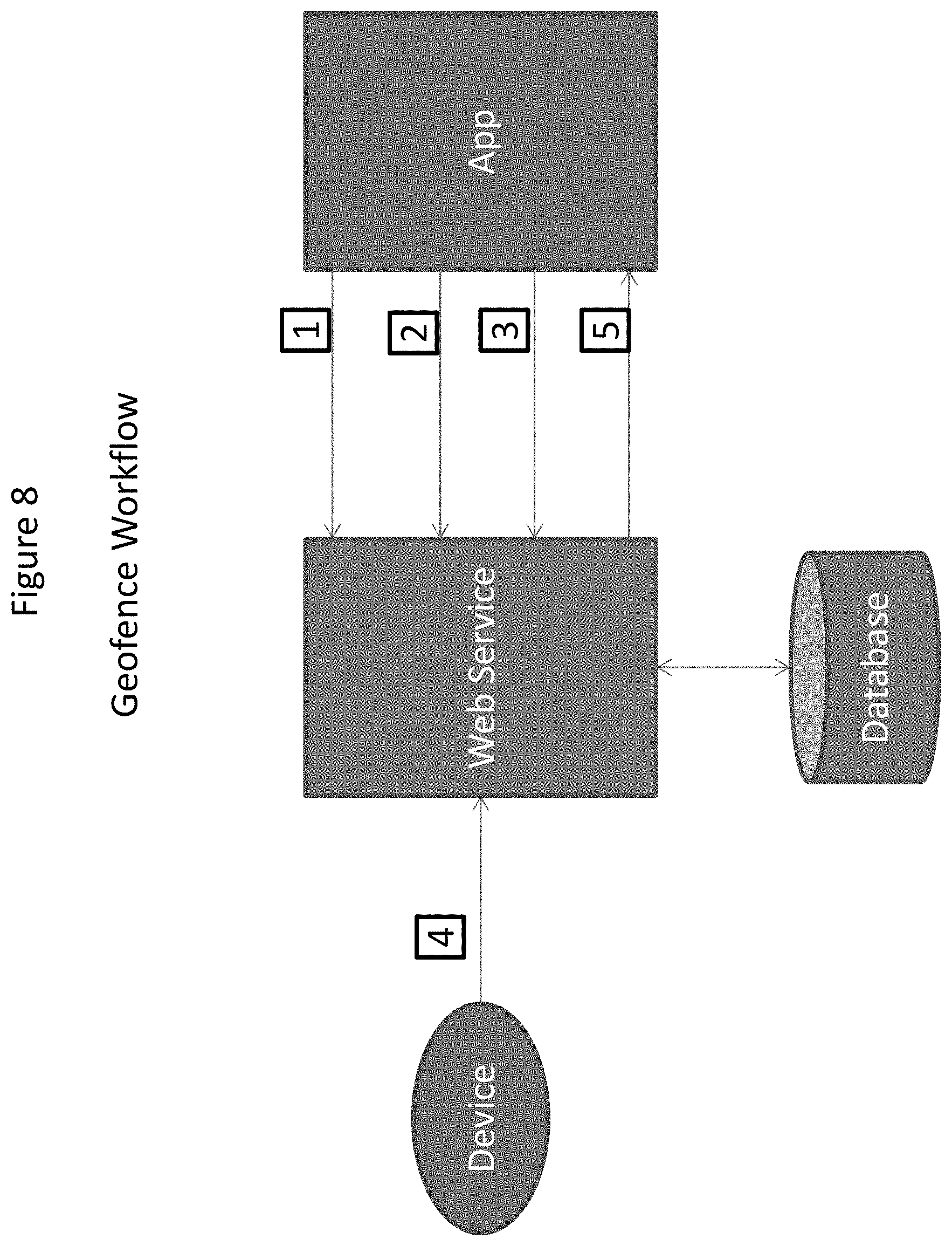
FIG. 8 illustrates an example of Geofence workflow according to an embodiment of the present invention.
FIG. 9 illustrates an example of Geofence configuration according to an embodiment of the present invention.
FIG. 10 illustrates an example of criteria for evaluating a Geofence according to an embodiment of the present invention.
FIG. 11 illustrates an example of user defined location attributes according to an embodiment of the present invention.
FIG. 12 illustrates a data processing system 1200 suitable for storing the computer program product and/or executing program code relating to the choices of the users in accordance with an embodiment of the present invention.
DETAILED DESCRIPTION
The present invention relates generally to providing a system and method monitoring devices relative to a user defined geographic area using an enablement platform for building web sites and web applications using data storage, management and publication capabilities of hosted web services.
The following description is presented to enable one of ordinary skill in the art to make and use the invention and is provided in the context of a patent application and its requirements. Various modifications to the preferred embodiments and the generic principles and features described herein will be readily apparent to those skilled in the art. Thus, the present invention is not intended to be limited to the embodiments shown, but is to be accorded the widest scope consistent with the principles and features described herein.
Machine to machine (M2M) network communications involves technologies to communicate with other devices often of similar abilities, different from traditional cellular communication networks for instance. In basic M2M environments, a device having limited logic (such as a sensor, meter, etc.) and limited resources (such as computing power) is resident at a location to typically captured measurable event data (such as temperature, pressure, quantity, etc.). The device is connected through a communications network to a remote computer or server having an application layer of specific software. The data received from the device is converted to relevant information associated with the measured event data through the application and may often thereafter undergo analysis or further similar assessment. In many cases a device, when activated, may trigger and communicate the events it is intended for so that those communicated events will then be acted upon by other machines, applications, and/or users on the network.
M2M environments often involve systems of networks, wired and wireless, that are to be connected to the internet and include personal appliances and similar devices. In M2M networks, typically devices may stationary or mobile and be connected via wired or wireless access protocols, often through WiFi network protocols or a 3GPP Mobile network protocol. These devices may also have seasonal and/or elastic connectivity needs (e.g., agricultural business needs, store and forward capability). Often in busy M2M networks, there is an `always on` device being used such as a general packet radio services (GPRS) or internet gateway. However, M2M communication infrastructure remains most suited to the communication needs and patterns of devices having similar abilities, characteristically, for communicating with other systems and devices on the same network.
An application for monitoring M2M devices may want to know if a device location is within or outside a geographical boundary and/or access other data regarding that device. For example, an application may want to know if a delivery truck has left its depot or has arrived at its designated next stop at certain time or speed of that truck at a particular time. This can be difficult due to limited logic as well as limited resources available to an M2M device.
Although a system and method in accordance with the present invention is described with respect to an application for monitoring devices relative to an user defined geographic area using an enablement platform for building web sites and web applications using data storage, management and publication capabilities of hosted web services, in M2M domain, as used herein the term "application" is intended to be inclusive, interchangeable, and/or synonymous with other similar applications as described further below, though one will recognize that functionally different types of applications may have characteristics, functions and/or operations which may be specific to their individual capabilities and/or deployment.
The present invention provides a system and method for monitoring devices relative to an user defined geographic area using an enablement platform which enables setting up new instances by collecting the required information from the user and feeding it to the necessary pages of the Hosted Data Service (HDS) in the background and developing production-ready M2M applications, using data storage, management and publication capabilities of hosted web services by providing easy-to-use software tools or widgets provided on an "out of the box" basis and an Application Programming Interface (API) that interacts with the instance at the HDS.
The enablement platform hereinafter is referred to as AerCloud Application Express (AAE) Launcher and AAE, where AAE Launcher is used with a data management and publication service. Aercloud Application Express (AAE) is an application which is used to create new applications for use of data from M2M devices. This is an application running at a website that uses a simple interface (the Aercloud Application Express User Interface, or AAE UI) to help users who already have an instance at a HDS that can receive device data to develop production-ready M2M applications using easy-to-use software tools (widgets) provided on an "out of the box" basis and an Application Programming Interface (API) that interacts with the instance at the HDS. Once the user has used AAE Launcher to create a new instance for an application using Aeris AerCloud data management and publication service, the user is able to quickly develop production-ready M2M applications using AerCloud API and widgets provided on an "out of the box" basis at the AAE UI using AAE.
One such widget "Geofence" provides a system and method for creating user defined geographic area using an enablement platform for building web sites and web applications using data storage and management capabilities of web services. Geofence is built on existing AerCloud concepts by allowing user to define location attributes and by using the user defined location attributes to configure and evaluate geofence as described below.
System Configuration page invites users to begin creation of applications via Aercloud Application Express, first by entering their user credentials for their AerCloud account and, if applicable, a key for incorporating maps provided by commercially available mapping products into applications that use a map. Next, "The Live Map" application widget allows users to create applications that allow tracking of devices and their activity relative to a geographic area using commercially available mapping products.
This is achieved by creating "geofences", which are alerts that send notifications when devices have, for example, entered a user-defined geographic area, left that area, or engaged in (or failed to engage in) certain behavior while located within that area. The invention simplifies the method provided by mapping products for defining the boundaries of the geofence using the drawing tool and provides superior flexibility for setting alerts based on device behavior (such as which devices inside the geofence are behaving outside permitted parameters).
Creation and use of this application includes creating a new alert, seeing all the existing alerts, seeing the detail of the alert in a draggable overlay widget. In the draggable overlay widget, the user is permitted to: enter criteria for a new alert, update the selected alert, delete the selected alert and/or enter name of the alert.
While doing so, the user is permitted to select a shape for geo-fence, click the Add button in the select a geo-fence shape view to enable geo-fence drawing mode using the simplified tool. Other operations for issuing an alert based on user defined geographic area "geofence" included in the widget are, for example: 1. See an instruction of what to do while in the geo-fence mode in a green popup. i.e. "Click and drag the mouse on the map to draw a circle." 2. Remove the geo-fence you have just drawn 3. Set whether the alert should be executed when the device is inside of the geo-fence or outside of the geo-fence, 4. Set a condition with parameters retrieved from AerCloud 5. Inline create an existing condition 6. Inline delete an existing condition.
To describe the features of the present invention in more detail within the context of monitoring devices relative to a user defined geographic area "geofence" and for issuing alerts, refer to the accompanying figures in conjunction with the following discussions. These examples are used for purpose of illustration only, and should not be construed as limitations.
FIG. 1 is a diagram illustrating various steps involved in creation of application using an enablement platform according to an embodiment of the present invention. First, a user signs in Aercloud Application Express (AAE) using a valid user name and password. System Configuration page then invites the user via step 102 to begin creation of applications. The Live Map application allows users to create applications via step 104 that allow tracking of devices and their activity relative to a geographic area using commercially available mapping products. The user can then create "geofences" via step 106, which are alerts that send notifications when devices have, for example, entered a user-defined geographic area, left that area, or engaged in (or failed to engage in) certain behavior while located within that area.
FIG. 2 is a diagram illustrating "Live Map", a widget provided by Application Express allowing users to create applications for tracking of devices and their activity relative to a geographic area using commercially available mapping products according to an embodiment of the present invention.
FIG. 3 is a diagram illustrating "Live Map", a widget provided by Application Express allowing users to configure alerts according to an embodiment of the present invention.
FIG. 4 is a diagram illustrating "Live Map", a widget provided by Application Express allowing users to configure alerts by adding "geofence" according to an embodiment of the present invention.
FIG. 5 is a diagram illustrating "Device Entry" a widget provided by Application Express and its interaction with "Device Details" widget illustrating types of location data returned by the Live Map and "Chart" application widgets according to an embodiment of the present invention.
FIG. 6 is a flow diagram illustrating different steps 602-612 involved in creating a user defined "geofence" according to an embodiment of the present invention, as described above. For example, the user is permitted to select a shape for geo-fence, by clicking the Add button in the select a geo-fence shape view to enable geo-fence drawing mode using the simplified tool. Other operations for issuing an alert based on user defined geographic area "geofence" included in the widget are, for example,: 1. See an instruction of what to do while in the geo-fence mode in a green popup. i.e. "Click and drag the mouse on the map to draw a circle." 2. Remove the geo-fence you have iust drawn 3. Set whether the alert should be executed when the device is inside of the geo-fence or outside of the geo-fence, 4. Set a condition with parameters retrieved from AerCIoud 5. Inline create an existing condition 6. Inline delete an existing condition. When a user selects a shape, for example circle, polygon via step 602, geo-fence drawing functionality is enabled via step 604. Once the user is done drawing a structure, data is added to the structure via step 606. The data is sent to AerCloud when the user clicks an Apply button on the widget via step 608. The user can draw as many geofences as they want and send them to AerCloud via step 610. The geo-fence data is sent to Aercloud via step 612 with following properties also defined in the widget: 1. Setting assumptions, such as "speed. >, 100 km/hr"; 2. One of the following eventType: a. "INSIDE"--The geo-fence rule matches when a device location is within the any area in the geo-fence: b. "OUTSIDE"--The geo-fence rule matches when a device location is outside all areas in the geo-fence: 3. Setting radius for size of the circle shape; and 4. Setting areaId that will be used in notification for INSIDE type of geo-fence.
FIG. 7 illustrates an example of data structure that is sent to AerCloud according to an embodiment of the present invention.
FIG. 8 illustrates an example of Geofence workflow according to an embodiment of the present invention. Geofence is built on existing AerCloud concepts by allowing user to define location attributes and by using the user defined location attributes to configure and evaluate geofence parameters as described below. The application works by posting a data model with user-defined location attributes, which is saved in a database with a model id. It then posts a data container associated to the data model, which is saved in a database with a container id. A subscription is posted to the container with a geofence, which is saved in a database with a subscription id and its corresponding container id and device location data is posted to the container id. The web service component first reads the geofence associated with the subscription and the user-defined location attributes from the data model associated with the container. Then the web service extracts location from the device data using user-defined location attribute names. According to one embodiment, the location information is then used to evaluate the geofence rule.
FIG. 9 illustrates an example of Geofence configuration according to an embodiment of the present invention. A shown in FIG. 9, a geofence can contain multiple geographical areas but each area must be a valid GeoJSON object with some required properties such as "areaId" which is used for notifying INSIDE event type and "radius" which is required if the object type is Point. Its value is the radius of a circle in meters.
FIG. 10 illustrates an example of criteria for evaluating a Geofence according to an embodiment of the present invention. For Geofence "event type" "inside" the "trigger criteria" can be set as "The geofence rule is "true" if a device location is within any area defined in the fence, otherwise "false"." According to one embodiment, device data is sent to an application only if the geofence rule is evaluated to true. The data is decorated with the "area id" that triggered the fence. For Geofence "event type" "outside" the "trigger criteria" can be set as "The geofence rule is "true" if a device location is outside all area defined in the fence, otherwise "false"." Thus, according to one embodiment, device data is sent to the application only if the geofence rule is evaluated to true.
FIG. 11 illustrates an example of user defined location attributes according to an embodiment of the present invention. According to such an embodiment, user defined location attributes includes normalizing the data model definition using the "metadata" field. For example, for "normalized property", the description can be "LOC_LAT", "LOC_LON" and/or "LOC_ALT". "LOC_LAT" indicates that this data model parameter designates latitude. Default is "latitude". "LOC_LON" indicates that this data model parameter designates longitude. Default is "longitude" and "LOC_ALT" indicates that this data model parameter designates altitude. Default is "altitude".
For example, according to one embodiment,
TABLE-US-00001 { "id" : "myDeviceDataModel_1", "sclDataSchema" : { "id" : "mySchema_1", "encoding" : "JSON", "parameters" : [ { "name" : "deviceLatitude", "type" : "STRING", "isIndexed" : false, "metainfo" : { "uom" : "degree", "normalizedProperty" : "LOC_LAT" } }, { "name" : "deviceLongitude", "type" : "STRING", "isIndexed" : false, "metainfo" : { "uom" : "degree", "normalizedProperty" : "LOC_LON" } }, { "name" : "deviceAltitude", "type" : "STRING", "isIndexed" : false, "metainfo" : { "uom" : "degree", "normalizedProperty" : "LOC_ALT" } } ] } }
FIG. 12 illustrates a data processing system 1200, including an M2M device, suitable for storing the computer program product and/or executing program code in accordance with an embodiment of the present invention. The data processing system 1200 includes a processor 1202 coupled to memory elements 1204a-b through a system bus 1206. In other embodiments, the data processing system 1200 may include more than one processor and each processor may be coupled directly or indirectly to one or more memory elements through a system bus.
Memory elements 1204a-b can include local memory employed during actual execution of the program code, bulk storage, and cache memories that provide temporary storage of at least some program code in order to reduce the number of times the code must be retrieved from bulk storage during execution. As shown, input/output or I/O devices 1208a-b (including, but not limited to, keyboards, displays, pointing devices, etc.) are coupled to the data processing system 1200. I/O devices 1208a-b may be coupled to the data processing system 1200 directly or indirectly through intervening I/O controllers (not shown).
In FIG. 12, a network adapter 1210 is coupled to the data processing system 1202 to enable data processing system 1202 to become coupled to other data processing systems or remote printers or storage devices through communication link 1212. Communication link 1212 can be a private or public network. Modems, cable modems, and Ethernet cards are just a few of the currently available types of network adapters.
Embodiments described herein can take the form of an entirely hardware implementation, an entirely software implementation, or an implementation containing both hardware and software elements. Embodiments may be implemented in software, which includes, but is not limited to, application software, firmware, resident software, microcode, etc.
The steps described herein may be implemented using any suitable controller or processor, and software application, which may be stored on any suitable storage location or computer-readable medium. The software application provides instructions that enable the processor to cause the receiver to perform the functions described herein.
Furthermore, embodiments may take the form of a computer program product accessible from a computer-usable or computer-readable medium providing program code for use by or in connection with a computer or any instruction execution system. For the purposes of this description, a computer-usable or computer-readable medium can be any apparatus that can contain, store, communicate, propagate, or transport the program for use by or in connection with the instruction execution system, apparatus, or device.
The medium may be an electronic, magnetic, optical, electromagnetic, infrared, semiconductor system (or apparatus or device), or a propagation medium. Examples of a computer-readable medium include a semiconductor or solid state memory, magnetic tape, a removable computer diskette, a random access memory (RAM), a read-only memory (ROM), a rigid magnetic disk, and an optical disk. Current examples of optical disks include digital versatile disk (DVD), compact disk-read-only memory (CD-ROM), and compact disk-read/write (CD-R/W).
Any theory, mechanism of operation, proof, or finding stated herein is meant to further enhance understanding of the present invention and is not intended to make the present invention in any way dependent upon such theory, mechanism of operation, proof, or finding. It should be understood that while the use of the word preferable, preferably or preferred in the description above indicates that the feature so described may be more desirable, it nonetheless may not be necessary and embodiments lacking the same may be contemplated as within the scope of the invention, that scope being defined by the claims that follow.
As used herein the terms product, device, appliance, terminal, remote device, wireless asset, etc. are intended to be inclusive, interchangeable, and/or synonymous with one another and other similar communication-based equipment for purposes of the present invention though one will recognize that functionally each may have unique characteristics, functions and/or operations which may be specific to its individual capabilities and/or deployment.
As used herein the term M2M communication is understood to include methods of utilizing various connected computing devices, servers, clusters of servers, wired and/or wirelessly, which provide a networked infrastructure to deliver computing, processing and storage capacity as services where a user typically accesses applications through a connected means such as but not limited to a web browser, terminal, mobile application or similar while the primary software and data are stored on servers or locations apart from the devices.
Similarly, it is envisioned by the present invention that the term communications network includes communications across a network (such as that of a M2M but not limited thereto) using one or more communication architectures, methods, and networks, including but not limited to: Code Division Multiple Access (CDMA), Global System for Mobile Communications (GSM) ("GSM" is a trademark of the GSM Association), Universal Mobile Telecommunications System (UMTS), Long Term Evolution (LTE), fourth generation cellular systems (4G) LTE, wireless local area network (WLAN), and one or more wired networks.
Although the present invention has been described in accordance with the embodiments shown, one of ordinary skill in the art will readily recognize that there could be variations to the embodiments and those variations would be within the spirit and scope of the present invention. Accordingly, many modifications may be made by one of ordinary skill in the art without departing from the spirit and scope of the present invention.
* * * * *
References
-
arxiv.org/abs/1601.00428
-
sciencedirect.com/science/article/pii/S0167739X15002976
-
en.wikipedia.org/wiki/Virtual_machine
-
-
mygeotracking.com/solutions/pdf/geo_fencing_alerts.pdf
-
ibm.com/developerworks/cloud/library/cl-blockchain-for-cognitive-iot-apps2
-
repository.fuoye.edu.ng/bitstream/123456789/1441/1/DESIGN%20AND%20CONSTRUCTION%20%20OF%20A%20VEHICLE%20TRACKING%20AND%20ACCIDENT%20ALERT%20SYSTEM%20%20USING%20%20GPS%20%20AND%20GSM%20MODULE.pdf
-
business.att.com/solutions/Service/internet-of-things/vehicle-solutions/iot-connected-fleet
-
internetofthingsagenda.techtarget.com/blog/IoT-Agenda/IoT-ushers-in-a-new-era-for-supply-chain-fulfillment
-
ieeexplore.ieee.org
-
ieeexplore.ieee.org2010
D00000
D00001
D00002
D00003
D00004
D00005
D00006
D00007
D00008
D00009
D00010
D00011
D00012

XML
uspto.report is an independent third-party trademark research tool that is not affiliated, endorsed, or sponsored by the United States Patent and Trademark Office (USPTO) or any other governmental organization. The information provided by uspto.report is based on publicly available data at the time of writing and is intended for informational purposes only.
While we strive to provide accurate and up-to-date information, we do not guarantee the accuracy, completeness, reliability, or suitability of the information displayed on this site. The use of this site is at your own risk. Any reliance you place on such information is therefore strictly at your own risk.
All official trademark data, including owner information, should be verified by visiting the official USPTO website at www.uspto.gov. This site is not intended to replace professional legal advice and should not be used as a substitute for consulting with a legal professional who is knowledgeable about trademark law.