Systems and methods providing a computerized eyewear device to aid in welding
Matthews , et al. A
U.S. patent number 10,748,447 [Application Number 14/105,758] was granted by the patent office on 2020-08-18 for systems and methods providing a computerized eyewear device to aid in welding. This patent grant is currently assigned to LINCOLN GLOBAL, INC.. The grantee listed for this patent is Lincoln Global, Inc.. Invention is credited to Joseph A. Daniel, William T. Matthews.


| United States Patent | 10,748,447 |
| Matthews , et al. | August 18, 2020 |
Systems and methods providing a computerized eyewear device to aid in welding
Abstract
Systems and methods to aid a welder or welding student. A system may provide a real-world arc welding system or a virtual reality arc welding system along with a computerized eyewear device having a head-up display (HUD). The computerized eyewear device may be worn by a user under a conventional welding helmet as eye glasses are worn and may wirelessly communicate with a welding power source of a real-world arc welding system or a programmable processor-based subsystem of a virtual reality arc welding system.
| Inventors: | Matthews; William T. (Chesterland, OH), Daniel; Joseph A. (Sagamore Hills, OH) | ||||||||||
|---|---|---|---|---|---|---|---|---|---|---|---|
| Applicant: |
|
||||||||||
| Assignee: | LINCOLN GLOBAL, INC. (City of
Industry, CA) |
||||||||||
| Family ID: | 50884954 | ||||||||||
| Appl. No.: | 14/105,758 | ||||||||||
| Filed: | December 13, 2013 |
Prior Publication Data
| Document Identifier | Publication Date | |
|---|---|---|
| US 20140346158 A1 | Nov 27, 2014 | |
Related U.S. Patent Documents
| Application Number | Filing Date | Patent Number | Issue Date | ||
|---|---|---|---|---|---|
| 61827248 | May 24, 2013 | ||||
| Current U.S. Class: | 1/1 |
| Current CPC Class: | B23K 9/1006 (20130101); G09B 19/003 (20130101); G02B 27/017 (20130101); B23K 9/32 (20130101); A61F 9/06 (20130101); B23K 9/10 (20130101); G02B 27/0172 (20130101); G09B 9/00 (20130101); G09B 5/02 (20130101); B23K 9/0956 (20130101); B23K 9/321 (20130101); B23K 9/0953 (20130101); G09B 19/24 (20130101); G06K 9/00671 (20130101); B23K 37/00 (20130101); G02B 27/0176 (20130101); G06F 3/04883 (20130101); G02B 2027/0158 (20130101); G02B 2027/0138 (20130101); G02B 2027/0178 (20130101); G02B 2027/0187 (20130101); G02B 2027/014 (20130101); G06F 3/167 (20130101) |
| Current International Class: | G09B 19/24 (20060101); G09B 19/00 (20060101); G06F 3/0488 (20130101); G06F 3/16 (20060101); A61F 9/06 (20060101); G02B 27/01 (20060101); B23K 9/095 (20060101); B23K 9/32 (20060101); B23K 9/10 (20060101); G09B 5/02 (20060101); B23K 37/00 (20060101); G09B 9/00 (20060101); G06K 9/00 (20060101) |
| Field of Search: | ;345/8 ;219/130.01,147 ;2/8.2 |
References Cited [Referenced By]
U.S. Patent Documents
| 1159119 | November 1915 | Springer |
| D140630 | March 1945 | Garibay |
| D142377 | September 1945 | Dunn |
| D152049 | December 1948 | Welch |
| 2681969 | June 1954 | Burke |
| D174208 | March 1955 | Abidgaard |
| 2728838 | December 1955 | Barnes |
| D176942 | February 1956 | Cross |
| 2894086 | July 1959 | Rizer |
| 3035155 | May 1962 | Hawk |
| 3059519 | October 1962 | Stanton |
| 3356823 | December 1967 | Waters et al. |
| 3555239 | January 1971 | Kerth |
| 3621177 | November 1971 | McPherson et al. |
| 3654421 | April 1972 | Streetman et al. |
| 3739140 | June 1973 | Rotilio |
| 3866011 | February 1975 | Cole |
| 3867769 | February 1975 | Schow et al. |
| 3904845 | September 1975 | Minkiewicz |
| 3988913 | November 1976 | Metcalfe et al. |
| D243459 | February 1977 | Bliss |
| 4024371 | May 1977 | Drake |
| 4041615 | August 1977 | Whitehill |
| D247421 | March 1978 | Driscoll |
| 4124944 | November 1978 | Blair |
| 4132014 | January 1979 | Schow |
| 4237365 | December 1980 | Lambros et al. |
| 4280041 | July 1981 | Kiessliing et al. |
| 4280137 | July 1981 | Ashida et al. |
| 4314125 | February 1982 | Nakamura |
| 4359622 | November 1982 | Dostoomian et al. |
| 4375026 | February 1983 | Kearney |
| 4410787 | October 1983 | Kremers et al. |
| 4429266 | January 1984 | Traadt |
| 4452589 | June 1984 | Denison |
| D275292 | August 1984 | Bouman |
| D277761 | February 1985 | Korovin et al. |
| D280329 | August 1985 | Bouman |
| 4611111 | September 1986 | Baheti et al. |
| 4616326 | October 1986 | Meier et al. |
| 4629860 | December 1986 | Lindbom |
| 4677277 | June 1987 | Cook et al. |
| 4680014 | July 1987 | Paton et al. |
| 4689021 | August 1987 | Vasiliev et al. |
| 4707582 | November 1987 | Beyer |
| 4716273 | December 1987 | Paton et al. |
| D297704 | September 1988 | Bulow |
| 4867685 | September 1989 | Brush et al. |
| 4877940 | October 1989 | Bangs et al. |
| 4897521 | January 1990 | Burr |
| 4907973 | March 1990 | Hon |
| 4931018 | June 1990 | Herbst et al. |
| 4998050 | March 1991 | Nishiyama et al. |
| 5034593 | July 1991 | Rice et al. |
| 5061841 | October 1991 | Richardson |
| 5089914 | February 1992 | Prescott |
| 5192845 | March 1993 | Kirmsse et al. |
| 5206472 | April 1993 | Myking et al. |
| 5266930 | November 1993 | Ichikawa et al. |
| 5285916 | February 1994 | Ross |
| 5305183 | April 1994 | Teynor |
| 5320538 | June 1994 | Baum |
| 5337611 | August 1994 | Fleming et al. |
| 5360156 | November 1994 | Ishizaka et al. |
| 5360960 | November 1994 | Shirk |
| 5370071 | December 1994 | Ackermann |
| D359296 | June 1995 | Witherspoon |
| 5424634 | June 1995 | Goldfarb et al. |
| 5436638 | July 1995 | Bolas et al. |
| 5464957 | November 1995 | Kidwell et al. |
| D365583 | December 1995 | Viken |
| 5562843 | October 1996 | Yasumoto |
| 5670071 | September 1997 | Ueyama et al. |
| 5676503 | October 1997 | Lang |
| 5676867 | October 1997 | Allen |
| 5708253 | January 1998 | Bloch et al. |
| 5710405 | January 1998 | Solomon et al. |
| 5719369 | February 1998 | White et al. |
| D392534 | March 1998 | Degen et al. |
| 5728991 | March 1998 | Takada et al. |
| 5751258 | May 1998 | Fergason et al. |
| D395296 | June 1998 | Kaye et al. |
| D396238 | July 1998 | Schmitt |
| 5781258 | July 1998 | Debral et al. |
| 5823785 | October 1998 | Matherne, Jr. |
| 5835077 | November 1998 | Dao et al. |
| 5835277 | November 1998 | Hegg |
| 5845053 | December 1998 | Watanabe et al. |
| 5963891 | October 1999 | Walker et al. |
| 6008470 | December 1999 | Zhang et al. |
| 6049059 | April 2000 | Kim |
| 6051805 | April 2000 | Vaidya et al. |
| 6114645 | September 2000 | Burgess |
| 6155475 | December 2000 | Ekelof et al. |
| 6155928 | December 2000 | Burdick |
| 6230327 | May 2001 | Briand et al. |
| 6236013 | May 2001 | Delzenne |
| 6236017 | May 2001 | Smartt et al. |
| 6242711 | June 2001 | Cooper |
| 6271500 | August 2001 | Hirayama et al. |
| 6330938 | December 2001 | Nerve et al. |
| 6330966 | December 2001 | Eissfeller |
| 6331848 | December 2001 | Stove et al. |
| D456428 | April 2002 | Aronson et al. |
| 6373465 | April 2002 | Jolly et al. |
| D456828 | May 2002 | Aronson et al. |
| D461383 | August 2002 | Balckburn |
| 6441342 | August 2002 | Hsu |
| 6445964 | September 2002 | White et al. |
| 6492618 | December 2002 | Flood et al. |
| 6506997 | January 2003 | Matsuyama |
| 6552303 | April 2003 | Blankenship et al. |
| 6560029 | May 2003 | Dobbie et al. |
| 6563489 | May 2003 | Latypov et al. |
| 6568846 | May 2003 | Cote et al. |
| D475726 | June 2003 | Suga et al. |
| 6572379 | June 2003 | Sears et al. |
| 6583386 | June 2003 | Ivkovich |
| 6621049 | September 2003 | Suzuki |
| 6624388 | September 2003 | Blankenship et al. |
| D482171 | November 2003 | Vui et al. |
| 6647288 | November 2003 | Madill et al. |
| 6649858 | November 2003 | Wakeman |
| 6655645 | December 2003 | Lu et al. |
| 6660965 | December 2003 | Simpson |
| 6697701 | February 2004 | Hillen et al. |
| 6697770 | February 2004 | Nagetgaal |
| 6703585 | March 2004 | Suzuki |
| 6708385 | March 2004 | Lemelson |
| 6710298 | March 2004 | Eriksson |
| 6710299 | March 2004 | Blankenship et al. |
| 6715502 | April 2004 | Rome et al. |
| D490347 | May 2004 | Meyers |
| 6730875 | May 2004 | Hsu |
| 6734393 | May 2004 | Friedl |
| 6744011 | June 2004 | Hu et al. |
| 6750428 | June 2004 | Okamoto et al. |
| 6772802 | August 2004 | Few |
| 6788442 | September 2004 | Potin et al. |
| 6795778 | September 2004 | Dodge et al. |
| 6798974 | September 2004 | Nakano et al. |
| 6857553 | February 2005 | Hartman et al. |
| 6858817 | February 2005 | Blankenship et al. |
| 6865926 | March 2005 | O'Brien et al. |
| D504449 | April 2005 | Butchko |
| 6920371 | July 2005 | Hillen et al. |
| 6940039 | September 2005 | Blankenship et al. |
| 7021937 | April 2006 | Simpson et al. |
| 7126078 | October 2006 | Demers et al. |
| 7132617 | November 2006 | Lee et al. |
| 7170032 | January 2007 | Flood |
| 7194447 | March 2007 | Harvey et al. |
| 7247814 | July 2007 | Ott |
| D555446 | November 2007 | Picaza Ibarrondo |
| 7315241 | January 2008 | Daily et al. |
| D561973 | February 2008 | Kinsley et al. |
| 7353715 | April 2008 | Myers |
| 7363137 | April 2008 | Brant et al. |
| 7375304 | May 2008 | Kainec et al. |
| 7381923 | June 2008 | Gordon et al. |
| 7414595 | August 2008 | Muffler |
| 7465230 | December 2008 | LeMay et al. |
| 7478108 | January 2009 | Townsend et al. |
| D587975 | March 2009 | Aronson et al. |
| 7516022 | April 2009 | Lee et al. |
| D602057 | October 2009 | Osicki |
| 7621171 | November 2009 | O'Brien |
| D606102 | December 2009 | Bender et al. |
| 7631968 | December 2009 | Dobson |
| 7643890 | January 2010 | Hillen et al. |
| 7687741 | March 2010 | Kainec et al. |
| D614217 | April 2010 | Peters et al. |
| D615573 | May 2010 | Peters et al. |
| 7817162 | October 2010 | Bolick et al. |
| 7853645 | December 2010 | Brown et al. |
| D631074 | January 2011 | Peters et al. |
| 7874921 | January 2011 | Baszucki et al. |
| 7962967 | June 2011 | Becker |
| 7970172 | June 2011 | Hendrickson |
| 7972129 | July 2011 | O'Donoghue |
| 7991587 | August 2011 | Ihn |
| 8069017 | November 2011 | Hallquist |
| 8224881 | July 2012 | Spear et al. |
| 8248324 | August 2012 | Nangle |
| 8265886 | September 2012 | Bisiaux et al. |
| 8274013 | September 2012 | Wallace |
| 8287522 | October 2012 | Moses et al. |
| 8316462 | November 2012 | Becker et al. |
| 8363048 | January 2013 | Gering |
| 8365603 | February 2013 | Lesage et al. |
| 8512043 | August 2013 | Choquet |
| 8569646 | October 2013 | Daniel et al. |
| 8777629 | July 2014 | Kreindl et al. |
| 9073138 | July 2015 | Wills |
| 9352411 | May 2016 | Batzler |
| 2001/0045808 | November 2001 | Hietmann et al. |
| 2001/0052893 | December 2001 | Jolly et al. |
| 2002/0032553 | March 2002 | Simpson et al. |
| 2002/0046999 | April 2002 | Veikkolainen et al. |
| 2002/0050984 | May 2002 | Roberts |
| 2002/0085843 | July 2002 | Mann |
| 2002/0175897 | November 2002 | Pelosi |
| 2003/0000931 | January 2003 | Ueda et al. |
| 2003/0023592 | January 2003 | Modica et al. |
| 2003/0025884 | February 2003 | Hamana et al. |
| 2003/0106787 | June 2003 | Santilli |
| 2003/0111451 | July 2003 | Blankenship et al. |
| 2003/0172032 | September 2003 | Choquet |
| 2003/0234885 | December 2003 | Pilu |
| 2004/0020907 | February 2004 | Zauner et al. |
| 2004/0035990 | February 2004 | Ackeret |
| 2004/0050824 | March 2004 | Samler |
| 2004/0140301 | July 2004 | Blankenship et al. |
| 2005/0007504 | January 2005 | Fergason |
| 2005/0017152 | January 2005 | Fergason |
| 2005/0046584 | March 2005 | Breed |
| 2005/0050168 | March 2005 | Wen |
| 2005/0101767 | May 2005 | Clapham et al. |
| 2005/0103766 | May 2005 | Iizuka et al. |
| 2005/0103767 | May 2005 | Kainec et al. |
| 2005/0109735 | May 2005 | Flood |
| 2005/0128186 | June 2005 | Shahoian et al. |
| 2005/0133488 | July 2005 | Blankenship |
| 2005/0159840 | July 2005 | Lin et al. |
| 2005/0189336 | September 2005 | Ku |
| 2005/0199602 | September 2005 | Kaddani et al. |
| 2005/0230573 | October 2005 | Ligertwood |
| 2005/0252897 | November 2005 | Hsu |
| 2005/0275913 | December 2005 | Vesely et al. |
| 2005/0275914 | December 2005 | Vesely et al. |
| 2006/0014130 | January 2006 | Weinstein |
| 2006/0136183 | June 2006 | Choquet |
| 2006/0163227 | July 2006 | Hillen et al. |
| 2006/0169682 | August 2006 | Kainec et al. |
| 2006/0173619 | August 2006 | Brant et al. |
| 2006/0189260 | August 2006 | Sung |
| 2006/0207980 | September 2006 | Jacovetty et al. |
| 2006/0213892 | September 2006 | Ott |
| 2006/0214924 | September 2006 | Kawamoto et al. |
| 2006/0226137 | October 2006 | Huismann et al. |
| 2006/0252543 | November 2006 | Van Noland et al. |
| 2006/0258447 | November 2006 | Baszucki et al. |
| 2007/0034611 | February 2007 | Drius et al. |
| 2007/0038400 | February 2007 | Lee et al. |
| 2007/0045488 | March 2007 | Shin |
| 2007/0088536 | April 2007 | Ishikawa |
| 2007/0112889 | May 2007 | Cook et al. |
| 2007/0198117 | August 2007 | Wajihuddin |
| 2007/0211026 | September 2007 | Ohta |
| 2007/0221797 | September 2007 | Thompson et al. |
| 2007/0256503 | November 2007 | Wong et al. |
| 2007/0277611 | December 2007 | Portzgen et al. |
| 2007/0291035 | December 2007 | Vesely et al. |
| 2008/0031774 | February 2008 | Magnant et al. |
| 2008/0038702 | February 2008 | Choquet |
| 2008/0078811 | April 2008 | Hillen et al. |
| 2008/0078812 | April 2008 | Peters et al. |
| 2008/0117203 | May 2008 | Gering |
| 2008/0128398 | June 2008 | Schneider |
| 2008/0135533 | June 2008 | Ertmer et al. |
| 2008/0140815 | July 2008 | Brant et al. |
| 2008/0149686 | July 2008 | Daniel et al. |
| 2008/0203075 | August 2008 | Feldhausen et al. |
| 2008/0233550 | September 2008 | Solomon |
| 2008/0314887 | December 2008 | Stoger et al. |
| 2009/0015585 | January 2009 | Klusza |
| 2009/0021514 | January 2009 | Klusza |
| 2009/0045183 | February 2009 | Artelsmair et al. |
| 2009/0057286 | March 2009 | Ihara et al. |
| 2009/0152251 | June 2009 | Dantinne et al. |
| 2009/0173726 | July 2009 | Davidson et al. |
| 2009/0184098 | July 2009 | Daniel et al. |
| 2009/0200281 | August 2009 | Hampton |
| 2009/0200282 | August 2009 | Hampton |
| 2009/0231423 | September 2009 | Becker |
| 2009/0259444 | October 2009 | Dolansky et al. |
| 2009/0298024 | December 2009 | Batzler et al. |
| 2009/0325699 | December 2009 | Delgiannidis |
| 2010/0012017 | January 2010 | Miller |
| 2010/0012637 | January 2010 | Jaeger |
| 2010/0048273 | February 2010 | Wallace et al. |
| 2010/0062405 | March 2010 | Zboray et al. |
| 2010/0062406 | March 2010 | Zboray |
| 2010/0096373 | April 2010 | Hillen et al. |
| 2010/0121472 | May 2010 | Babu et al. |
| 2010/0133247 | June 2010 | Mazumder et al. |
| 2010/0133250 | June 2010 | Sardy et al. |
| 2010/0176107 | July 2010 | Bong |
| 2010/0201803 | August 2010 | Melikian |
| 2010/0223706 | September 2010 | Becker |
| 2010/0224610 | September 2010 | Wallace |
| 2010/0276396 | November 2010 | Cooper et al. |
| 2010/0299101 | November 2010 | Shimada et al. |
| 2010/0307249 | December 2010 | Lesage et al. |
| 2011/0006047 | January 2011 | Penrod et al. |
| 2011/0060568 | March 2011 | Goldfine et al. |
| 2011/0091846 | April 2011 | Kreindl et al. |
| 2011/0114615 | May 2011 | Daniel et al. |
| 2011/0116076 | May 2011 | Chantry et al. |
| 2011/0117527 | May 2011 | Conrardy et al. |
| 2011/0122495 | May 2011 | Togashi |
| 2011/0183304 | July 2011 | Wallace et al. |
| 2011/0248864 | October 2011 | Becker et al. |
| 2011/0316516 | December 2011 | Schiefermuller et al. |
| 2012/0189993 | July 2012 | Kindig et al. |
| 2012/0291172 | November 2012 | Wills et al. |
| 2012/0298640 | November 2012 | Conrardy et al. |
| 2013/0026150 | January 2013 | Chantry et al. |
| 2013/0040270 | February 2013 | Albrecht |
| 2013/0044042 | February 2013 | Olsson |
| 2013/0075380 | March 2013 | Albrech et al. |
| 2013/0189657 | July 2013 | Wallace et al. |
| 2013/0189658 | July 2013 | Peters et al. |
| 2013/0206741 | August 2013 | Pfeifer |
| 2014/0038143 | February 2014 | Daniel et al. |
| 2014/0134580 | May 2014 | Becker |
| 2014/0263224 | September 2014 | Becker |
| 2014/0272836 | September 2014 | Becker |
| 2014/0272837 | September 2014 | Becker |
| 2014/0272838 | September 2014 | Becker |
| 2015/0056584 | February 2015 | Boulware et al. |
| 2015/0056585 | February 2015 | Boulware et al. |
| 2015/0056586 | February 2015 | Penrod et al. |
| 2698078 | Sep 2011 | CA | |||
| 201083660 | Jul 2008 | CN | |||
| 101419755 | Apr 2009 | CN | |||
| 201229711 | Apr 2009 | CN | |||
| 101571887 | Nov 2009 | CN | |||
| 101587659 | Nov 2009 | CN | |||
| 102165504 | Aug 2011 | CN | |||
| 103871279 | Jun 2014 | CN | |||
| 105209207 | Dec 2015 | CN | |||
| 28 33 638 | Feb 1980 | DE | |||
| 30 46 634 | Jan 1984 | DE | |||
| 32 44 307 | May 1984 | DE | |||
| 35 22 581 | Jan 1987 | DE | |||
| 4037879 | Jun 1991 | DE | |||
| 196 15 069 | Oct 1997 | DE | |||
| 197 39 720 | Oct 1998 | DE | |||
| 19834205 | Feb 2000 | DE | |||
| 200 09 543 | Aug 2001 | DE | |||
| 10 2005 047 204 | Apr 2007 | DE | |||
| 10 2010 038 902 | Feb 2012 | DE | |||
| 202012013151 | Feb 2015 | DE | |||
| 0 108 599 | May 1984 | EP | |||
| 0 127 299 | Dec 1984 | EP | |||
| 0 145 891 | Jun 1985 | EP | |||
| 319623 | Oct 1990 | EP | |||
| 0852986 | Jul 1998 | EP | |||
| 1010490 | Jun 2000 | EP | |||
| 1 527 852 | May 2005 | EP | |||
| 1905533 | Apr 2008 | EP | |||
| 2 274 736 | May 2007 | ES | |||
| 2274736 | May 2007 | ES | |||
| 1456780 | Mar 1965 | FR | |||
| 2 827 066 | Jan 2003 | FR | |||
| 2 926 660 | Jul 2009 | FR | |||
| 1 455 972 | Nov 1976 | GB | |||
| 1 511 608 | May 1978 | GB | |||
| 2 254 172 | Sep 1992 | GB | |||
| 2435838 | Sep 2007 | GB | |||
| 2 454 232 | May 2009 | GB | |||
| 2454232 | Jun 2009 | GB | |||
| 2-224877 | Sep 1990 | JP | |||
| 05-329645 | Dec 1993 | JP | |||
| 07-047471 | Feb 1995 | JP | |||
| 07-232270 | Sep 1995 | JP | |||
| 08-505091 | Apr 1996 | JP | |||
| 08-150476 | Jun 1996 | JP | |||
| 08-132274 | May 1998 | JP | |||
| 2000237872 | May 2000 | JP | |||
| 2000-167666 | Jun 2000 | JP | |||
| 2001-071140 | Mar 2001 | JP | |||
| 2002278670 | Sep 2002 | JP | |||
| 2003-200372 | Jul 2003 | JP | |||
| 2003240562 | Aug 2003 | JP | |||
| 2003-326362 | Nov 2003 | JP | |||
| 2006-006604 | Jan 2006 | JP | |||
| 2006-281270 | Oct 2006 | JP | |||
| 2007-290025 | Nov 2007 | JP | |||
| 2009-500178 | Jan 2009 | JP | |||
| 2009160636 | Jul 2009 | JP | |||
| 2310019646 | Jan 2010 | JP | |||
| 2012024867 | Feb 2012 | JP | |||
| 2013504437 | Feb 2013 | JP | |||
| 20090010693 | Jan 2009 | KR | |||
| 2008 108 601 | Nov 2009 | RU | |||
| 1038963 | Aug 1983 | SU | |||
| 98/45078 | Oct 1998 | WO | |||
| 0112376 | Feb 2001 | WO | |||
| 01/43910 | Jun 2001 | WO | |||
| 0158400 | Aug 2001 | WO | |||
| 2006034571 | Apr 2006 | WO | |||
| 2009120921 | Jan 2009 | WO | |||
| 2009060231 | May 2009 | WO | |||
| 2009149740 | Dec 2009 | WO | |||
| 2010000003 | Jan 2010 | WO | |||
| 2010044982 | Apr 2010 | WO | |||
| 2010091493 | Aug 2010 | WO | |||
| 2011045654 | Apr 2011 | WO | |||
| 2011058433 | May 2011 | WO | |||
| 2011058433 | May 2011 | WO | |||
| 2011067447 | Jun 2011 | WO | |||
| 2011/097035 | Aug 2011 | WO | |||
| 2011097035 | Aug 2011 | WO | |||
| 2012082105 | Jun 2012 | WO | |||
| 2012143327 | Oct 2012 | WO | |||
| 20121327060 | Oct 2012 | WO | |||
| 2013014202 | Jan 2013 | WO | |||
| 2013025672 | Feb 2013 | WO | |||
| 2013114189 | Aug 2013 | WO | |||
| 2013175079 | Nov 2013 | WO | |||
| 2014007830 | Jan 2014 | WO | |||
| 2014019045 | Feb 2014 | WO | |||
| 2014020386 | Feb 2014 | WO | |||
| 2014140682 | Sep 2014 | WO | |||
Other References
|
Chuansong Wu: "Microcomputer-based welder training simulator", Computers in Industry, vol. 20, No. 3, Oct. 1992, pp. 321-325, XP000205597, Elsevier Science Publishers, Amsterdam, NL. cited by applicant . SIMFOR / CESOL, "RV-SOLD" Welding Simulator, Technical and Functional Features, 20 pages, no date available. cited by applicant . International Search Report for PCT/IB2009/00605. cited by applicant . "Design and Implementation of a Video Sensor for Closed Loop Control of Back Bead Weld Puddle Width," Robert Schoder, Massachusetts, Institute of Technology, Dept. of Mechanical Engineering, May 27, 1983. cited by applicant . Hills and Steele, Jr.; "Data Parallel Algorithms", Communications of the ACM, Dec. 1986, vol. 29, No. 12, p. 1170. cited by applicant . Russell and Norvig, "Artificial Intelligence: A Modern Approach", Prentice-Hall (Copywrite 1995). cited by applicant . Mechanisms and Mechanical Devices Source Book, Chironis, Neil Sclater; McGraw Hill; 2nd Addition, 1996. cited by applicant . ARS Electronica Linz GmbH, Fronius, 2 pages, May 18, 1997. cited by applicant . "Penetration in Spot GTA Welds during Centrifugation, "D.K. Aidun and S.A. Martin; Journal of Material Engineering and Performance vol. 7(5) Oct. 1998--597. cited by applicant . Arc+ simulator; httl://www.123arc.com/en/depliant_ang.pdf; 2000. cited by applicant . Wade, "Human uses of ultrasound: ancient and modern", Ulrasonics vol. 38, dated 2000. cited by applicant . ASME Definitions, Consumables, Welding Positions, dated Mar. 19, 2001. See http://www.gowelding.com/asme4.htm. cited by applicant . Code Aster (Software) EDF (France), Oct. 2001. cited by applicant . "The influence of fluid flow phenomena on the laser beam welding process"; International Journal of Heat and Fluid Flow 23, dated 2002. cited by applicant . The Lindoln Electric Company; CheckPoint Production Monitoring brochure; four (4) pages; http://www.lincolnelectric.com/assets/en_US/products/literature/s232.pdf; Publication 82.32; Issue Date Feb. 2012. cited by applicant . "Numerical Analysis of Metal Transfer in Gas Metal Arc Welding," G. Wang, P.G. Huang, and Y.M. Zhang. Departments of Mechanical and Electrical Engineering. University of Kentucky, Dec. 10, 2001. cited by applicant . Desroches, X.; Code-Aster, Note of use for aciculations of welding; Instruction manual U2.03 booklet: Thermomechincal; Document: U2.03.05; Oct. 1, 2003. cited by applicant . Fast, K. et al., "Virtual Training for Welding", Mixed and Augmented Reality, 2004, ISMAR 2004, Third IEEE and SM International Symposium on Arlington, VA, Nov. 2-5, 2004. cited by applicant . Cooperative Research Program, Virtual Reality Welder Training, Summary Report SR 0512, 4 pages, Jul. 2005. cited by applicant . Porter, et al., Virtual Reality Training, Paper No. 2005-P19, 14 pages, 2005. cited by applicant . Eduwelding+, Weld Into the Future; Online Welding Seminar--A virtual training environment; 123arc.com; 4 pages, 2005. cited by applicant . Miller Electric Mfg Co.; MIG Welding System features weld monitoring software; NewsRoom 2010 (Dialog.RTM. File 992); .COPYRGT. 2011 Dialog. 2010; http://www.dialogweb.com/cgi/dwclient?reg=133233430487; three (3) pages; printed Mar. 8, 2012. cited by applicant . Numerical simulation to study the effect of tack welds and root gap on welding deformations and residual stresses of a pipe-flange joint by M. Abida and M. Siddique, Faculty of Mechanical Engineering, GIK Institute of Engineering Sciences and Technology, Topi, NWFP, Pakistan. Available on-line Aug. 25, 2005. cited by applicant . Abbas, M. et. al.; Code_Aster; Introduction to Code_Aster; User Manual; Booklet U1.0--: Introduction to Code_Aster; Document: U1.02.00; Version 7.4; Jul. 22, 2005. cited by applicant . Mavrikios D et al, A prototype virtual reality-based demonstrator for immersive and interactive simulation of welding processes, International Journal of Computer Integrated manufacturing, Taylor and Francis, Basingstoke, GB, vol. 19, No. 3, Apr. 1, 2006, pp. 294-300. cited by applicant . Virtual Reality Welder Trainer, Sessiion 5: Joining Technologies for Naval Applications: earliest date Jul. 14, 2006 (http://weayback.archive.org) by Nancy C. Porter, Edision Welding Institute; J. Allan Cote, General Dynamics Electric Boat; Timothy D. Gifford, VRSim, and Wim Lam, FCS Controls. cited by applicant . 16th International Shop and Offshore Structures Congress: Aug. 20-25, 2006: Southhampton, UK, vol. 2 Specialist Committee V.3 Fabrication Technology Committee Mandate: T Borzecki, G. Bruce, Y.S. Han, M. Heinemann, A Imakita, L. Josefson, W. Nie, D. Olson, F. Roland, and Y. Takeda. cited by applicant . Ratnam and Khalid: "Automatic classification of weld defects using simulated data and an MLP neutral network." Insight vol. 49, No. 3; Mar. 2007. cited by applicant . Wang et al., Study on welder training by means of haptic guidance and virtual reality for arc welding, 2006 IEEE International Conference on Robotics and Biomimetics, ROBIO 2006 ISBN-10: 1424405718, p. 954-958. cited by applicant . CS Wave, The Virtual Welding Trainer, 6 pages, 2007. cited by applicant . asciencetutor.com, A division of Advanced Science and Automation Corp., VWL (Virtual Welding Lab), 2 pages, 2007. cited by applicant . Eric Linholm, John Nickolls, Stuart Oberman, and John Montrym, "NVIDIA Testla: A Unifired Graphics and Computing Architecture", IEEE Computer Society, 2008. cited by applicant . NSRP ASE, Low-Cost Virtual Realtiy Welder Training System, 1 Page, 2008. cited by applicant . Edison Welding Institute, E-Weld Predictor, 3 pages, 2008. cited by applicant . CS Wave, A Virtual learning tool for welding motion, 10 pages, Mar. 14, 2008. cited by applicant . The Fabricator, Virtual Welding, 4 pages, Mar. 2008. cited by applicant . N. A. Tech., P/NA.3 Process Modeling and Optimization, 11 pages, Jun. 4, 2008. cited by applicant . FH Joanneum, Fronius--virtual welding, 2 pages, May 12, 2008. cited by applicant . Eduwelding+, Training Activities with arc+ simulator; Weld Into the Future, Online Welding Simulator--A virtual training environment; 123arc.com; 6 pages, May 2008. cited by applicant . ChemWeb.com, Journal of Materials Engineering and Performance (v.7, #5), 3 pgs., printed Sep. 26, 2012. cited by applicant . Choquet, Claude; "ARC+: Today's Virtual Reality Solution for Welders" Internet Page, Jan. 1, 2008. cited by applicant . Juan Vicenete Rosell Gonzales, "RV-Sold: simulator virtual para la formacion de soldadores"; Deformacion Metalica, Es. vol. 34, No. 301 Jan. 1, 2008. cited by applicant . White et al., Virtual welder training, 2009 IEEE Virtual Reality Conference, p. 303, 2009. cited by applicant . Training in a virtual environment gives welding students a leg up, retrieved on Apr. 12, 2010 from: http://www.thefabricator.com/article/arcwelding/virtually-welding. cited by applicant . Sim Welder, retrieved on Apr. 12, 2010 from: http://www.simwelder.com. cited by applicant . P. Beatriz Garcia-Allende, Jesus Mirapeix, Olga M. Conde, Adolfo Cobo and Jose M. Lopez-Higuera; Defect Detection in Arc-Welding Processes by Means of the Line-to-Continuum Method and Feature Selection; www.mdpi.com/journal/sensors; Sensors 2009, 9, 7753-7770; doi; 10.3390/s91007753. cited by applicant . Production Monitoring 2 brochure, four (4) pages, The Lincoln Electric Company, May 2009. cited by applicant . International Search Report and Written Opinion from PCT/IB10/02913 dated Apr. 19, 2011. cited by applicant . Bjorn G. Agren; Sensor Integration for Robotic Arc Welding; 1995; vol. 5604C of Dissertations Abstracts International p. 1123; Dissertation Abs Online (Dialog.RTM. File 35): .COPYRGT. 2012 ProQuest Info& Learning: http://dialogweb.com/cgi/dwclient?req=1331233317524; one (1) page; printed Mar. 8, 2012. cited by applicant . Heat and mass transfer in gas metal arc welding. Part 1: the arc by J. Hu and Hi Tsai found in ScienceDirect, International Journal of Heat and Mass Transfer 50 (2007) 833-846 Available on Line on Oct. 24, 2006 http://www.web.mst.edu/.about.tsai/publications/HU-IJHMT-2007-1-60.pdf. cited by applicant . Texture Mapping by M. Ian Graham, Carnegie Mellon University Class 15-462 Computer Graphics, Lecture 10 dated Feb. 13, 2003. cited by applicant . ViziTech USA, retrieved on Mar. 27, 2014 from http://vizitechusa.com/, 2 pages. cited by applicant . Guu and Rokhlin ,Technique for Simultaneous Real-Time Measurements of Weld Pool Surface Geometry and Arc Force, 10 pages, Dec. 1992. cited by applicant . D. Mavrikios, V. Karabatsou, D. Fragos and G. Chryssolouris, A prototype virtual reality-based demonstrator for immersive and interactive simulation of welding processes, International Journal of Computer Integrated Manufacturing, abstract, 1 page, Apr.-May 2006, 294-300, vol. 19, No. 3, http://eds.a.ebscohost.com/eds/pdfviewer/pdfviewer?vid=2&sid=ab8fe67b-1 f7. cited by applicant . S.B. Chen, L. Wu, Q. L. Wang and Y. C. Liu, Self-Learning Fuzzy Neural Networks and Computer Vision for Control of Pulsed GTAW, 9 pages, dated May 1997. cited by applicant . Patrick Rodjito, Position tracking and motion prediction using Fuzzy Logic, 81 pages, 2006, Colby College. cited by applicant . D'Huart, Deat, and Lium; Virtual Environment for Training, 6th International Conference, ITS 20002, 6 pages, Jun. 2002. cited by applicant . Konstantinos Nasios (Bsc), Improving Chemical Plant Safety Training Using Virtual Reality, Thesis submitted to the University of Nottingham for the Degree of Doctor of Philosophy, 313 pages, Dec. 2001. cited by applicant . Nancy C. Porter, J. Allan Cote, Timothy D. Gifford, and Wim Lam, Virtual Reality Welder Training, 29 pages, dated Jul. 14, 2006. cited by applicant . J.Y. (Yosh) Mantinband, Hillel Goldenberg, Llan Kleinberger, Paul Kleinberger, Autosteroscopic, field-sequential display with full freedom of movement Or Let the display were the shutter-glasses, 3ality (Israel) Ltd., 2002. cited by applicant . Echtler et al, "17 The Intelligent Welding Gun: Augmented Reality for Experimental Vehicle Construction," Virtual and Augmented Reality Applications in Manufacturing (2003) pp. 1-27. cited by applicant . Teeravarunyou et al, "Computer Based Welding Training System," International Journal of Industrial Engineering (2009) 16(2): 116-125. cited by applicant . Antonelli et al, "A Semi-Automated Welding Station Exploiting Human-Robot Interaction," Advanced Manufacturing Systems and Technology (2011) pp. 249-260. cited by applicant . Praxair Technology Inc, "The RealWeld Trainer System: Real Weld Training Under Real Conditions" Brochure (2013) 2 pages. cited by applicant . United States Provisional Patent Application for "System for Characterizing Manual Welding Operations on Pipe and Other Curved Structures," U.S. Appl. No. 62/055,724, filed Sep. 26, 2014, 35 pages. cited by applicant . Lincoln Global, Inc., "VRTEX 360: Virtual Reality Arc Welding Trainer" Brochure (2015) 4 pages. cited by applicant . Wuhan Onew Technology Co Ltd, "ONEW-360 Welding Training Simulator" http://en.onewtech.com/_d276479751.htm as accessed on Jul. 10, 2015, 12 pages. cited by applicant . The Lincoln Electric Company, "VRTEX Virtual Reality Arc Welding Trainer," http://www.lincolnelectric.com/en-us/equipment/training-equipment/Pages/v- rtex.aspx as accessed on Jul. 10, 2015, 3 pages. cited by applicant . Miller Electric Mfg Co, "LiveArc: Welding Performance Management System" Owner's Manual, (Jul. 2014) 64 pages. cited by applicant . Miller Electric Mfg Co, "LiveArc Welding Performance Management System" Brochure, (Dec. 2014) 4 pages. cited by applicant . Steve Mann, Raymond Chun Bing Lo, Kalin Ovtcharov, Shixiang Gu, David Dai, Calvin Ngan, Tao Ai, Realtime HDR (High Dynamic Range) Video for Eyetap Wearable Computers, FPGS-Based Seeing Aids, and Glasseyes (Eyetaps), 2012 25th IEEE Canadian Conference on Electrical and Computer Engineering (CCECE),pp. 1-6, 6 pages, Apr. 29, 2012. cited by applicant . Kyt Dotson, Augmented Reality Welding Helmet Prototypes How Awsome the Technology Can Get, Sep. 26, 2012, Retrieved from the Internet: URL:http://siliconangle.com/blog/2012/09/26/augmented-reality-welding-hel- met-prototypes-how-awesome-the-technology-can-get/,1 page, retrieved on Sep. 26, 2014. cited by applicant . Terrence O'Brien, "Google's Project Glass gets some more details",Jun. 27, 2012 (Jun. 27, 2012), Retrieved from the Internet: http://www.engadget.com/2012/06/27/googles-project-glass-gets-some-more-d- etails/, 1 page, retrieved on Sep. 26, 2014. cited by applicant . Yao, et al., `Development of a Robot System for Pipe Welding`. 2010 International Conference on Measuring echnology and Mechatronics Automation. Retrieved from the Internet: http://ieeexplore.ieee.org/stamp/stamp.jsp?tp=&arnumber=5460347&tag=1; pp. 1109-1112, 4 pages, 2010. cited by applicant . ANSI/A WS D 10.11 MID 10. 11 :2007 Guide for Root Pass Welding of Pipe without Backing Edition: 3rd American Welding Society / Oct. 13, 2006/36 pages ISBN: 0871716445, 6 pagess, 2007. cited by applicant . M. Jonsson, L. Karlsson, and L-E Lindgren, Simulation of Tack Welding Procedures in Butt Joint Welding of Plates Welding Research Supplement, 7 pages, Oct. 1985. cited by applicant . Isaac Brana Veiga, Simulation of a Work Cell in the IGRIP Program , 50 pages, dated 2006. cited by applicant . Balijepalli, A. and Kesavadas, Haptic Interfaces for Virtual Environment and Teleoperator Systems, Haptics 2003, 7-.,Department of Mechanical & Aerospace Engineering, State University of New York at Buffalo, NY, 7 pages, 2003. cited by applicant . Johannes Hirche, Alexander Ehlert, Stefan Guthe, Michael Doggett, Hardware Accelerated Per-Pixel Displacement Mapping, 8 pages. cited by applicant . William T. Reeves, "Particles Systems--A Technique for Modeling a Class of Fuzzy Objects", Computer Graphics 17:3 pp. 359-376, 17 pages, 1983. cited by applicant . T. Borzecki, G. Bruce, YS. Han, et al., Specialist Committee V.3 Fabrication Technology Committee Mandate, Aug. 20-25, 2006, 49 pages, vol. 2, 16th International Ship and Offshore Structures Congress, Southampton, UK. cited by applicant . G. Wang, P.G. Huang, and Y.M. Zhang: "Numerical Analysis of Metal Transfer in Gas Metal Arc Welding": Departments of Mechanical Engineering; and Electrical and Computer Engineering, University of Kentucky, Lexington, KY 40506-0108, Dec. 10, 2001, 10 pages. cited by applicant . ISMAR 2004 The Third IEEE and ACM International Symposium on Mixed and Augmented reality; Nov. 2-5, Arlington, VA, USA. cited by applicant . Kenneth Fast, et al.; National Shipbuilding Research Program (NSRP); Virtual Welding--a Low Cost Virtual Reality Welder Training System; Phase II Final Report Feb. 29, 2012. cited by applicant . The Application of Micro-computer in Robotic Technologies. cited by applicant. |
Primary Examiner: Hoang; Tu B
Assistant Examiner: Ward; Thomas J
Parent Case Text
INCORPORATION BY REFERENCE
This U.S. patent application claims priority to and the benefit of U.S. provisional patent application Ser. No. 61/827,248 filed on May 24, 2013, which is incorporated herein by reference in its entirety. Published U.S. patent applications (US 2013/0044042) having application Ser. No. 13/212,686 and filed on Aug. 18, 2013 is incorporated by reference herein in its entirety. Published U.S. patent applications (US 2010/0062405) having application Ser. No. 12/501,257 and filed on Jul. 10, 2009 is incorporated by reference herein in its entirety.
Claims
What is claimed is:
1. An arc welding system, comprising: a welding power source; and a computerized eyewear device configured to be worn by a user as eye glasses are worn, while also wearing a protective welding helmet, wherein the computerized eyewear device includes a transparent head-up display (HUD), which displays an augmented reality image to the user performing a welding operation with the welding power source, a wireless communication interface, a processor, and a memory storing computer-executable instructions, wherein the computer-executable instructions configure the computerized eyewear device to: communicate with the welding power source via the wireless communication interface, display information related to the welding power source on the HUD as part of the augmented reality image, and provide weld sequence support to the user to guide the user through a sequence of two or more welds associated with a workpiece through incorporation of support information in the augmented reality image displayed on the HUD, wherein, upon completion of a weld of the sequence, the augmented reality image displays the support information indicating a next weld of the sequence to be performed on the workpiece.
2. The system of claim 1, wherein the information related to the welding power source includes at least one welding parameter associated with the welding operation.
3. The system of claim 1, wherein the computerized eyewear device further includes a microphone configured to receive voice-activated user command information and wirelessly transmit the voice-activated user command information to the welding power source.
4. The system of claim 1, wherein the computerized eyewear device further includes a camera configured to capture one or more of still pictures and moving video.
5. The system of claim 1, wherein the computerized eyewear device is configured to access the internet through a wireless access point.
6. The system of claim 1, wherein the computerized eyewear device further includes a frame configured to be worn on the head of a user.
7. The system of claim 6, wherein the computerized eyewear device further includes at least one housing affixed to the frame containing one or more of the the processor, the wireless communication interface, the memory, a microphone, and a camera.
8. The system of claim 6, wherein the HUD is affixed to the frame and is movable with respect to the frame through rotation about a first axis that extends parallel to a brow portion of the frame.
9. The system of claim 6, wherein the computerized eyewear device further includes at least one prescription optical lens held in place by the frame.
10. The system of claim 6, wherein the frame includes a bridge configured to be supported on the nose of the user, a brow portion coupled to and extending away from the bridge to a first end remote therefrom and configured to be positioned over a first side of a brow of the user, and a first arm having a first end coupled to the first end of the brow portion and extending to a free end, the first arm being configured to be positioned over a first temple of the user with the free end disposed near a first ear of the user.
11. The system of claim 10, wherein the bridge is adjustable for selective positioning of the brow portion relative to an eye of the user.
12. The system of claim 2, wherein the augmented reality image displayed on the HUD depicts an indication of whether the at least one welding parameter is within an acceptable range.
Description
TECHNICAL FIELD
Certain embodiments of the present invention relate to welding. More particularly, certain embodiments of the present invention relate to systems and methods providing visualization and communication capabilities to a welder using a welding system via a computerized eyewear device.
BACKGROUND
Providing information to a welding student in real time during a welding process (whether a real-world welding process or a simulated welding process) is important to aid the welding student in the learning process. Similarly, providing information to an expert welder in real time during a real-world welding process can aid the expert welder in the welding process. Furthermore, providing the ability for a welding student or an expert welder to easily communicate with (e.g., provide commands to) a welding system (real or simulated) can allow for a more efficient and user-friendly welding experience. Today, a welding helmet may be provided with simple light indicators representative of welding information which don't require a welder to be able to focus sharply on the light indicators, since the light indicators may be within one inch of the welder's eye. Simply being able to see that the color of a light indicator is red or green or yellow, for example, is provided. Thus, there is an ongoing need to improve how a welder or welding student interacts with a welding system and how information is provided and viewed in real time.
Further limitations and disadvantages of conventional, traditional, and proposed approaches will become apparent to one of skill in the art, through comparison of such systems and methods with embodiments of the present invention as set forth in the remainder of the present application with reference to the drawings.
SUMMARY
In one embodiment, a system is provided. The system includes a welding power source of an arc welding system and a computerized eyewear device having a head-up display (HUD). The computerized eyewear device is configured to be worn by a user as eye glasses are worn, while the user also wears a protective welding helmet. The computerized eyewear device is further configured to wirelessly communicate with the welding power source of the arc welding system. The computerized eyewear device may receive information from the welding power source and display the information on the HUD. Furthermore, the user may provide commands to the welding power source via the computerized eyewear device (e.g., via voice activation). The welding power source and the computerized eyewear device may be cooperatively configured to provide one or more of augmented indicators indicative of a user's welding technique and sequencer functionality indicative of a next weld to be made on the HUD, for example.
In another embodiment, a system is provided. The system includes a programmable processor-based subsystem of a virtual reality welding simulation system and a computerized eyewear device having a head-up display (HUD). The computerized eyewear device is configured to be worn by a user as eye glasses are worn, while the user also wears a protective welding helmet. The computerized eyewear device is further configured to wirelessly communicate with the programmable processor-based subsystem of the virtual reality welding simulation system. The computerized eyewear device may receive information from the programmable processor-based subsystem and display the information on the HUD. Furthermore, the user may provide commands to the programmable processor-based subsystem via the computerized eyewear device (e.g., via voice activation). The programmable processor-based subsystem and the computerized eyewear device may be cooperatively configured to provide one or more of virtual reality images associated with a virtual reality welding process and virtual cues and indicators associated with a virtual reality welding process on the HUD, for example.
In accordance with an embodiment, the computerized eyewear device includes a frame configured to be worn on the head of a user, the frame including a bridge configured to be supported on the nose of the user, a brow portion coupled to and extending away from the bridge to a first end remote therefrom and configured to be positioned over a first side of a brow of the user, and a first arm having a first end coupled to the first end of the brow portion and extending to a free end, the first arm being configured to be positioned over a first temple of the user with the free end disposed near a first ear of the user, wherein the bridge is adjustable for selective positioning of the brow portion relative to an eye of the user. The computerized eyewear device also includes a transparent display (the HUD) which may be affixed to the frame and may be movable with respect to the frame through rotation about a first axis that extends parallel to the first brow portion. The computerized eyewear device also includes a housing containing control and communication circuitry affixed to the frame. As an example, the computerized eyewear device may be a Google Glass.TM. device configured for operation with an arc welding system or a virtual reality arc welding simulation system.
Details of illustrated embodiments of the present invention will be more fully understood from the following description and drawings.
BRIEF DESCRIPTION OF THE DRAWINGS
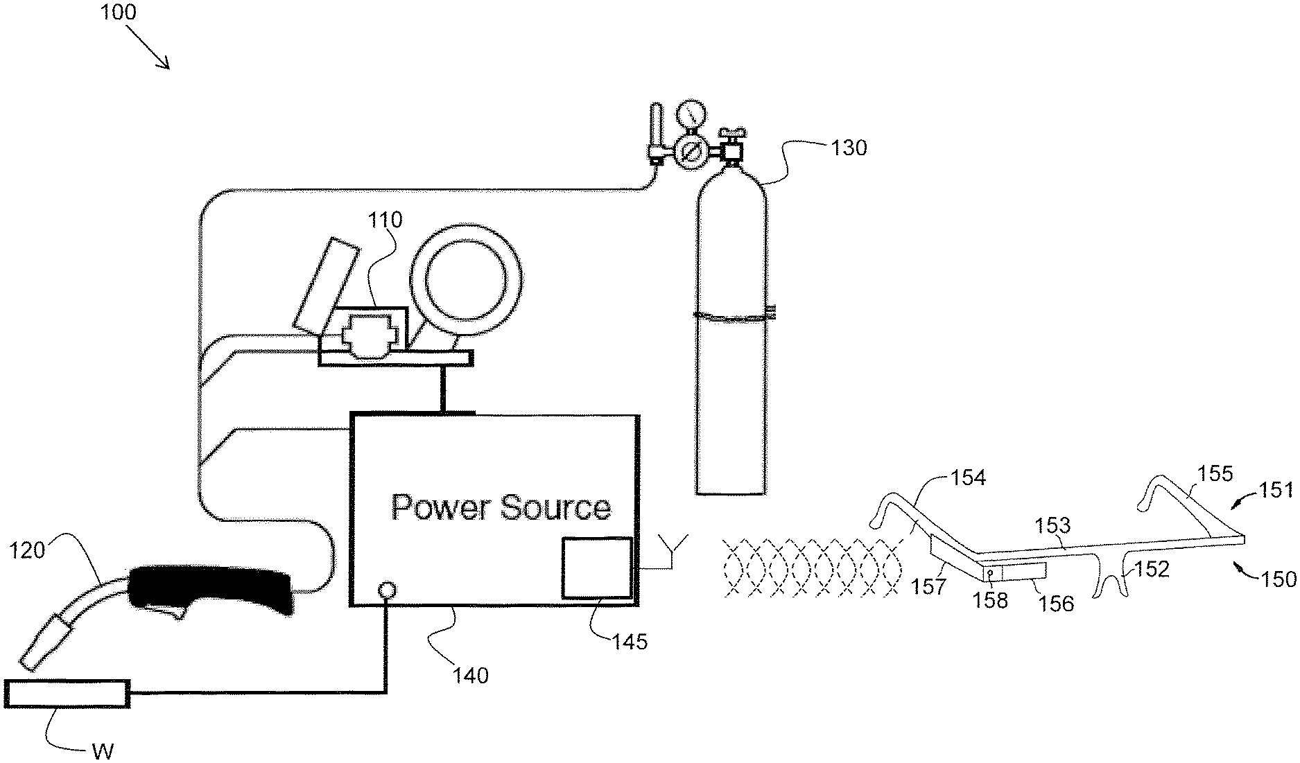
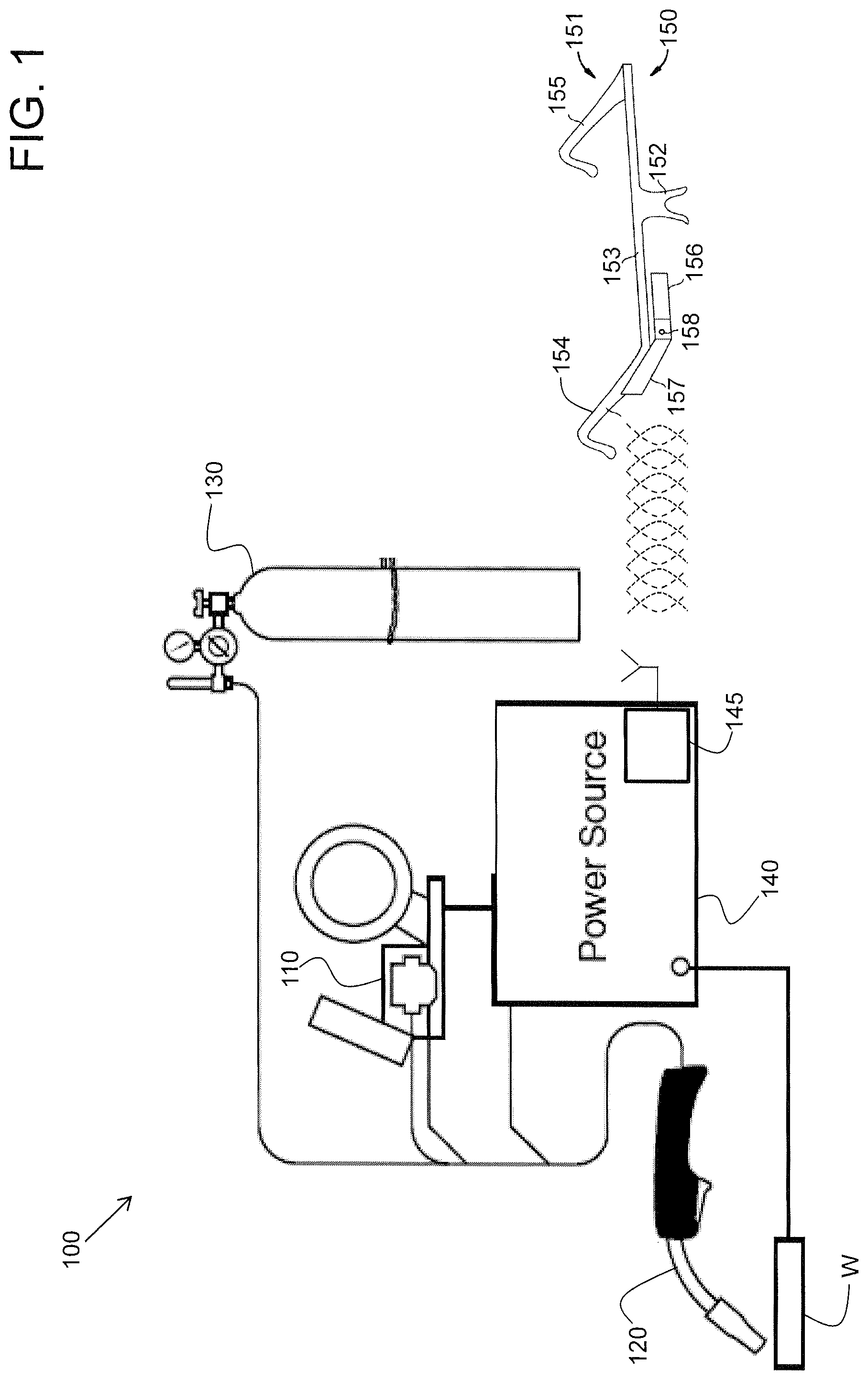
FIG. 1 illustrates a diagram of an exemplary embodiment of an arc welding system and a computerized eyewear device configured to communicate with the arc welding system;
FIG. 2 illustrates a diagram of an exemplary embodiment of the computerized eyewear device of FIG. 1; and
FIG. 3 illustrates a diagram of an exemplary embodiment of a virtual reality welding system and a computerized eyewear device configured to communicate with the virtual reality welding system.
DETAILED DESCRIPTION
The following are definitions of exemplary terms that may be used within the disclosure. Both singular and plural forms of all terms fall within each meaning:
"Software" or "computer program" as used herein includes, but is not limited to, one or more computer readable and/or executable instructions that cause a computer or other electronic device to perform functions, actions, and/or behave in a desired manner. The instructions may be embodied in various forms such as routines, algorithms, modules or programs including separate applications or code from dynamically linked libraries. Software may also be implemented in various forms such as a stand-alone program, a function call, a servlet, an applet, an application, instructions stored in a memory, part of an operating system or other type of executable instructions. It will be appreciated by one of ordinary skill in the art that the form of software is dependent on, for example, requirements of a desired application, the environment it runs on, and/or the desires of a designer/programmer or the like.
"Computer" or "processing element" or "computerized device" as used herein includes, but is not limited to, any programmed or programmable electronic device that can store, retrieve, and process data. "Non-transitory computer-readable media" include, but are not limited to, a CD-ROM, a removable flash memory card, a hard disk drive, a magnetic tape, and a floppy disk.
"Computer memory", as used herein, refers to a storage device configured to store digital data or information which can be retrieved by a computer or processing element.
"Controller", as used herein, refers to the logic circuitry and/or processing elements and associated software or program involved in controlling a device, system, or portion of a system.
The terms "signal", "data", and "information" may be used interchangeably herein and may be in digital or analog form.
The term "welding parameter" is used broadly herein and may refer to characteristics of a portion of a welding output current waveform (e.g., amplitude, pulse width or duration, slope, electrode polarity), a welding process (e.g., a short arc welding process or a pulse welding process), wire feed speed, a modulation frequency, a welding travel speed, or some other parameter associated with real-world welding or simulated welding.
The term "head up display", as used herein, refers to a transparent display that presents information (e.g., high quality images) without requiring a user to look away from their usual viewpoints.
In one embodiment, an arc welding system is provided. The arc welding system includes a welding power source and a computerized eyewear device having a head-up display (HUD) and control and communication circuitry (CCC) operatively connected to the HUD. The computerized eyewear device is configured to be worn by a user as eye glasses are worn, while also wearing a protective welding helmet, and wirelessly communicate with the welding power source. The control and communication circuitry is configured to wirelessly receive information from the welding power source and display the information on the HUD.
In accordance with an embodiment, the computerized eyewear device includes a microphone operatively connected to the control and communication circuitry. The microphone and the control and communication circuitry are configured to receive voice-activated user command information and wirelessly transmit the voice-activated user command information to the welding power source. In accordance with an embodiment, the computerized eyewear device includes a camera operatively connected to the control and communication circuitry. The camera and the control and communication circuitry are configured to capture one or more of still pictures and moving video. In accordance with an embodiment, the control and communication circuitry is configured to access the internet through a wireless access point.
In accordance with an embodiment, the computerized eyewear device includes a frame configured to be worn on the head of a user and at least one housing affixed to the frame containing one or more of the control and communication circuitry, the microphone, and the camera. The HUD is also affixed to the frame and is movable with respect to the frame through rotation about a first axis that extends parallel to a first brow portion. Optionally, the computerized eyewear device may include at least one prescription optical lens held in place by the frame.
In accordance with an embodiment, the frame includes a bridge configured to be supported on the nose of the user, a brow portion coupled to and extending away from the bridge to a first end remote therefrom and configured to be positioned over a first side of a brow of the user, and a first arm having a first end coupled to the first end of the brow portion and extending to a free end. The first arm is configured to be positioned over a first temple of the user with the free end disposed near a first ear of the user. In accordance with an embodiment, the bridge is adjustable for selective positioning of the brow portion relative to an eye of the user.
FIG. 1 illustrates a diagram of an exemplary embodiment of an arc welding system 100 and a computerized eyewear device 150 configured to communicate with the arc welding system 100. The arc welding system 100 includes a wire feeder 110, a welding gun or tool 120, a shielding gas supply 130, and a welding power source 140. The wire feeder 110, the welding gun 120, the shielding gas supply 130, and the power source 140 are operatively connected to allow a welder to create an electric arc between a welding wire and a workpiece W to create a weld as is well known in the art.
In accordance with an embodiment, the welding power source 140 includes a switching power supply (not shown), a waveform generator (not shown), a controller (not shown), a voltage feedback circuit (not shown), a current feedback circuit (not shown), and a wireless communication circuit 145. The wire feeder 110 feeds the consumable wire welding electrode E toward the workpiece W through the welding gun (welding tool) 120 at a selected wire feed speed (WFS). The wire feeder 110, the consumable welding electrode E, and the workpiece W are not part of the welding power source 140 but may be operatively connected to the welding power source 140 via a welding output cable.
The computerized eyewear device 150 is configured to be worn by a user as eye glasses are worn, while also wearing a conventional protective welding helmet. The protective welding helmet may be a conventional welding helmet that does not have to be modified in any way to accommodate the computerized eyewear device 150. Furthermore, the computerized eyewear device 150 is configured to wirelessly communicate with the welding power source 140 via the wireless communication circuit 145 of the welding power source 140. The wireless communication circuit 145 may include a processor, computer memory, a transmitter, a receiver, and an antenna, in accordance with an embodiment.
Referring now to FIG. 1 and FIG. 2, where FIG. 2 illustrates a diagram of an exemplary embodiment of the computerized eyewear device 150 of FIG. 1, the computerized eyewear device 150 includes a frame 151 configured to be worn on the head of a user. The frame 151 includes a bridge 152 configured to be supported on the nose of the user and a brow portion 153 coupled to and extending away from the bridge 152 to a first and second ends remote therefrom and configured to be positioned over the brows of the user.
The frame also includes a first arm 154 having a first end coupled to the first end of the brow portion 153 and extending to a free end, the first arm being configured to be positioned over a first temple of the user with the free end disposed near a first ear of the user. The frame 151 also includes a second arm 155 having a first end coupled to the second end of the brow portion 153 and extending to a free end, the second arm being configured to be positioned over a second temple of the user with the free end disposed near a second ear of the user. The bridge 152 may be adjustable for selective positioning of the brow portion 153 relative to the eyes of the user, in accordance with an embodiment.
The computerized eyewear device 150 includes a transparent display (e.g., a HUD) 156 affixed to the frame 151. The HUD 156 may be movable with respect to the frame 151 through rotation about a first axis that extends parallel to the brow portion 153, in accordance with an embodiment, and may be configured to display text, graphics, and images. The computerized eyewear device 150 also includes control and communication circuitry (e.g., a computer) 157 enclosed in a housing 162 and affixed to the frame 151. The control and communication circuitry 157 may include a processor and memory, for example. The memory may be coupled to the processor and store software that can be accessed and executed by the processor. The processor may be a microprocessor or a digital signal processor, for example. As an option, the computerized eyewear device 150 may include a camera 158. The HUD 156 and the control and communication circuitry 157 (and, optionally, the camera 158) are operatively connected to provide the functionality described herein. In accordance with an embodiment, the camera 158 is configured to capture still pictures and moving video. In this way, a user may record the welding scenario as viewed by the user from inside the welding helmet.
In accordance with an embodiment, the control and communication circuitry 157 provides two-way communication with the wireless communication circuit 145 of the welding power source 140. Information may be provided from the welding power source 140 to the computerized eyewear device 150 and displayed on the HUD 156. Furthermore, in accordance with an embodiment, the control and communication circuitry 157 is configured to accept voice-activated commands from a user and transmit the commands to the welding power source 140. Communication between the welding power source 140 and the computerized eyewear device 150 may be accomplished by way of, for example, Bluetooth.RTM. radio technology, communication protocols described in IEEE 802.11 (including any IEEE 802.11 revisions), cellular technology (such as GSM, CDMA, UMTS, EVDO, WiMax, or LTE), or ZigBee.RTM. technology, among other possibilities. In accordance with an embodiment, the computerized eyewear device may also include at least one optical lens 163 that matches a user's corrective visual prescription. In accordance with a further embodiment, the computerized eyewear device may be modular and attachable to normal prescription eye glasses.
Furthermore, in accordance with an embodiment, the welding power source 140 may be accessible by the computerized eyewear device 150 via the Internet. For example, the control and communication circuitry 157 may be configured to access the Internet through a wireless hot spot (e.g., a smart phone or a wireless router) and access the welding power source 140 therethrough. Alternatively, the welding power source 140 may be configured to access the Internet and provide information obtained from the Internet to the computerized eyewear device 150.
Information that may be displayed on the HUD 156 during a real-world welding scenario that may be useful to a welder may be in the form of text, an image, or a graphic. Such information may include, for example, the arc welding process, a welding tool travel angle, a welding tool travel speed, a tip-to-work distance, a wire feed speed, a welding polarity, an output voltage level, an output current level, an arc length, a dime spacing, a whip time, a puddle time, a width of weave, a weave spacing, a tolerance window, a number score, and welding sequence steps. Other information may be displayed as well, in accordance with other embodiments. For example, in an augmented mode, instructional indicators that are used in a virtual reality training environment may be superimposed over an actual weld using the HUD 156. In this manner, a welding student who trained on a virtual reality welding system can transition to a real welding scenario and have the same instructional indicators provided via the HUD. Visual cues or indicators may be displayed to the welder on the HUD of the computerized eyewear device to indicate to the welder if a particular parameter (e.g., a welding tool travel angle) is within an acceptable range or not. Such visual cues or indicators may aid in training by helping an inexperienced welder or welding student to improve his welding technique.
The acquisition of some of the information may rely on the welding tool being spatially tracked (e.g., travel angle, travel speed, tip-to-work distance). In accordance with an embodiment, the welding tool may include an accelerometer device that is operatively connected to the welding power source to provide spatial position or movement information. Other methods of tracking the welding tool are possible as well, such as magnetic tracking techniques, for example.
In accordance with an embodiment, the computerized eyewear device 150 includes a microphone 159 for receiving voice-activated commands from a user. The voice-activated commands, as initiated by a welder, that may be accommodated by the computerized eyewear device 150 in communication with the welding power source 140 may include, for example, commands to change a welding parameter such as a wire feed speed, a welding polarity, and a welding output current level. Other types of commands may be possible as well, in accordance with other embodiments.
In accordance with an embodiment, the computerized eyewear device 150 and/or the welding power source 140 may be programmed with one or more welding software applications configured to accommodate use of the computerized eyewear device 150 with the arc welding system 100. For example, an embodiment of one welding software application may provide a "good weld" recognition capability. Similar to a facial recognition capability, the "good weld" recognition capability may use the camera 158 to acquire an image of a weld created by the user, analyze the image, and provide feedback to the user on the HUD 156 as to the overall external quality of the weld. For example, the text "poor weld", "fair weld", or "good weld" may be displayed to the user. The user may have to take off his welding helmet or lift a visor on the welding helmet to acquire an image of the weld. The welding software application may reside in the computerized eyewear device 150, the welding power source 140, or a combination of both, in accordance with various embodiments.
As another example, an embodiment of a welding software application may provide a welding sequencing capability. When welding a part or assembly with many welds, it is not desirable for a welder to miss a weld. A welding software application may step a welder through the multiple welds for the part. For example, as a welder finishes a current weld on a part or assembly requiring multiple welds, the welder may give a voice command of "next weld". As a result, the welding software application may display to the welder on the HUD 156 an image or graphic (e.g., a 3D representation of the part) providing the location of the next weld to be performed. The type of weld and other information associated with the weld may also be displayed. In accordance with an embodiment where the computerized eyewear device 150 is being spatially tracked, as discussed later herein, the welding software application may display a graphic on the HUD such that graphic indicator is overlaid onto the assembly at the next location to be welded. Other types of welding software applications that operate with the computerized eyewear device are possible as well, in accordance with other embodiments.
In one embodiment, a virtual reality welding system is provided. The virtual reality welding system includes a programmable processor-based subsystem and a computerized eyewear device having a head-up display (HUD) and control and communication circuitry (CCC) operatively connected to the HUD. The computerized eyewear device is configured to be worn by a user as eye glasses are worn, and to wirelessly communicate with the programmable processor-based subsystem. The control and communication circuitry is configured to wirelessly receive information from the programmable processor-based subsystem and display the information on the HUD.
In accordance with an embodiment, the computerized eyewear device further includes a microphone operatively connected to the control and communication circuitry and configured to receive voice-activated user command information and wirelessly transmit the voice-activated user command information to the programmable processor-based subsystem. Alternatively, or in addition, the computerized eyewear device may include a touch-sensitive user interface operatively connected to the control and communication circuitry and configured to allow a user to select command information and wirelessly transmit the command information to the programmable processor-based subsystem.
In accordance with an embodiment, the computerized eyewear device includes a camera operatively connected to the control and communication circuitry. The camera and the control and communication circuitry are configured to capture one or more of still pictures and moving video. In accordance with an embodiment, the control and communication circuitry is configured to access the internet through a wireless access point.
In accordance with an embodiment, the computerized eyewear device includes a frame configured to be worn on the head of a user and at least one housing affixed to the frame containing one or more of the control and communication circuitry, the microphone, and the camera. The HUD is also affixed to the frame and is movable with respect to the frame through rotation about a first axis that extends parallel to a first brow portion. Optionally, the computerized eyewear device may include at least one prescription optical lens held in place by the frame.
In accordance with an embodiment, the frame includes a bridge configured to be supported on the nose of the user, a brow portion coupled to and extending away from the bridge to a first end remote therefrom and configured to be positioned over a first side of a brow of the user, and a first arm having a first end coupled to the first end of the brow portion and extending to a free end. The first arm is configured to be positioned over a first temple of the user with the free end disposed near a first ear of the user. In accordance with an embodiment, the bridge is adjustable for selective positioning of the brow portion relative to an eye of the user.
In accordance with an embodiment, the computerized eyewear device includes at least one motion sensing device operatively connected to the control and communication circuitry and configured to provide spatial information to the programmable processor-based subsystem as a user moves his head.
FIG. 3 illustrates a diagram of an exemplary embodiment of a virtual reality arc welding system 300 and a computerized eyewear device 150 configured to communicate with the virtual reality welding system 300. The virtual reality arc welding (VRAW) system includes a programmable processor-based subsystem, a spatial tracker operatively connected to the programmable processor-based subsystem, at least one mock welding tool capable of being spatially tracked by the spatial tracker, and at least one display device operatively connected to the programmable processor-based subsystem. In accordance with an embodiment, the computerized eyewear device 150 may also be spatially tracked by the spatial tracker. The system is capable of simulating, in a virtual reality space, a weld puddle having real-time molten metal fluidity and heat dissipation characteristics. The system is also capable of displaying the simulated weld puddle on the display device in real-time.
The system 300 includes a programmable processor-based subsystem (PPS) 310. The system 300 further includes a spatial tracker (ST) 320 operatively connected to the PPS 310. The system 300 also includes a physical welding user interface (WUI) 330 operatively connected to the PPS 310 as well as the computerized eyewear device 150 in operative wireless communication with the PPS 310 via a wireless communication circuit 145 of the PPS 310. The system 300 further includes an observer display device (ODD) 340 operatively connected to the PPS 310. The system 300 also includes at least one mock welding tool (MWT) 350 operatively connected to the ST 320 and the PPS 310. The system 300 further includes a table/stand (T/S) 360 and at least one welding coupon (WC) 370 capable of being attached to the T/S 360. In accordance with an alternative embodiment of the present invention, a mock gas bottle is provided (not shown) simulating a source of shielding gas and having an adjustable flow regulator.
In accordance with an embodiment, the computerized eyewear device 150 is configured as previously described herein. However, in this embodiment, the control and communication circuitry 157 provides two-way communication with the wireless communication circuit 145 of the PPS 310. Information may be provided from the PPS 310 to the computerized eyewear device 150 and displayed on the HUD 156. Furthermore, in accordance with an embodiment, the control and communication circuitry 157 is configured to accept voice-activated commands from a user and transmit the commands to the PPS 310. Communication between the PPS 310 and the computerized eyewear device 150 may be accomplished by way of, for example, Bluetooth.RTM. radio technology, communication protocols described in IEEE 802.11 (including any IEEE 802.11 revisions), cellular technology (such as GSM, CDMA, UMTS, EVDO, WiMax, or LTE), or ZigBee.RTM. technology, among other possibilities.
Furthermore, in accordance with an embodiment, the PPS 310 may be accessible by the computerized eyewear device 150 via the Internet. For example, the control and communication circuitry 157 may be configured to access the Internet through a wireless hot spot (e.g., a smart phone or a wireless router) and access the PPS 310 therethrough. Alternatively, the PPS 310 may be configured to access the Internet and provide information obtained from the Internet to the computerized eyewear device 150.
As before, the user may wear a conventional welding helmet over the computerized eyewear device 150. However, since the welding scenario is a simulated welding scenario, the conventional welding helmet may be fitted with a transparent lens instead of a protective lens that protects against the light and other radiation emitted by a real arc. As such, the user may see through the transparent lens to view the welding coupon 370 and the mock welding tool 350, for example.
In accordance with an embodiment, the computerized eyewear device 150 is configured with an accelerometer device 160 that is operatively connected to the control and communication circuitry 157. Spatial information provided by the accelerometer device as the user moves his head is communicated to the PPS 110 and then to the spatial tracker 320. In this manner, the spatial relationship between the surrounding environment and what the user is seeing through the HUD 156 of the computerized eyewear device 150 may be correlated. As the user proceeds with the virtual welding process using the system 300, anything displayed on the HUD 156 (e.g., a virtual weld puddle) will appear overlaid onto, for example, the welding coupon 370 as the user views the welding coupon through the transparent lens of the conventional welding helmet. In accordance with other embodiments, other motion sensing devices besides that of an accelerometer device may be used. A calibration procedure may be initially performed to correlate the view of the user through the HUD to the surrounding environment, in accordance with an embodiment.
The real-time molten metal fluidity and heat dissipation characteristics of the simulated weld puddle provide real-time visual feedback to a user of the mock welding tool when displayed (e.g., on the HUD of the computerized eyewear device 150 as tracked by the spatial tracker 320), allowing the user to adjust or maintain a welding technique in real-time in response to the real-time visual feedback (i.e., helps the user learn to weld correctly). When the computerized eyewear device 150 is being spatially tracked, the weld puddle will appear at a correct location with respect to the welding coupon as viewed through the HUD.
The displayed weld puddle is representative of a weld puddle that would be formed in the real-world based on the user's welding technique and the selected welding process and parameters. By viewing a puddle (e.g., shape, color, slag, size, stacked dimes), a user can modify his technique to make a good weld and determine the type of welding being done. The shape of the puddle is responsive to the movement of the gun or stick.
The term "real-time", as used herein with respect to a virtual reality or simulated environment, means perceiving and experiencing in time in a virtual or simulated environment in the same way that a user would perceive and experience in a real-world welding scenario. Furthermore, the weld puddle is responsive to the effects of the physical environment including gravity, allowing a user to realistically practice welding in various positions including overhead welding and various pipe welding angles (e.g., 1G, 2G, 5G, 6G).
Information that may be useful to a welding student to display on the HUD 156 during a virtual or simulated welding scenario may be in the form of text, an image, or a graphic. Such information may include, for example, the arc welding process, a welding tool travel angle, a welding tool travel speed, a tip-to-work distance, a set wire feed speed, a set welding polarity, a simulated output voltage level, a set output current level, a simulated arc length, a dime spacing, a whip time, a puddle time, a width of weave, a weave spacing, a tolerance window, a number score, and welding sequence steps. Other information may be displayed as well, in accordance with other embodiments.
In accordance with an embodiment, the computerized eyewear device 150 includes a microphone 159 that is operatively connected to the control and communication circuitry 157 for receiving voice-activated commands from a user. The voice-activated commands, as initiated by a welder, that may be accommodated by the computerized eyewear device 150 in communication with the PPS 310 may include, for example, commands to change a welding parameter such as a simulated wire feed speed, a simulated welding polarity, and a simulated welding output current level. Other types of commands may be possible as well, in accordance with other embodiments.
In accordance with an embodiment, the computerized eyewear device 150 and/or the PPS 310 may be programmed with one or more welding training software applications configured to accommodate use of the computerized eyewear device 150 with the virtual reality arc welding system 300. For example, an embodiment of one welding software application may provide a "good weld" recognition capability. Similar to a facial recognition capability, the "good weld" recognition capability may use an image of a simulated weld created by the user, analyze the image, and provide feedback to the user on the HUD 156 as to the overall external quality of the weld. For example, the text "poor weld", "fair weld", or "good weld" may be displayed to the user. The welding software application may reside in the computerized eyewear device 150, the PPS 310, or a combination of both, in accordance with various embodiments.
As another example, an embodiment of a welding software application may provide a welding sequencing capability. As a welder finishes a current simulated weld on a welding coupon requiring multiple welds, the welder may give a voice command of "next weld". As a result, the welding software application may display to the welder on the HUD 156 an image or graphic providing the location of the next weld to be performed. The type of weld and other information associated with the weld may also be displayed. In accordance with an embodiment where the computerized eyewear device 150 is being spatially tracked, as discussed herein, the welding software application may display a graphic on the HUD such that the graphic is overlaid onto the welding coupon at the next location to be welded. Other types of welding software applications that operate with the computerized eyewear device are possible as well, in accordance with other embodiments.
The computerized eyewear device 150 may be configured to be used with other welding simulation systems in accordance with other embodiments. For example, welding simulations performed on a personal computer (PC) or a tablet computer may be communicatively and functionally integrated with the computerized eyewear device 150 to aid a welding student in learning how to weld. In some simulated and/or virtual welding environments, a welding student may not wear a welding helmet of any kind. Instead, the computerized eyewear device may be the only head gear worn. One optional embodiment of the computerized eyewear device may provide a touch-sensitive user interface (TSUI) 161 which the welding student can use instead of or in addition to voice-activated commands. Such a TSUI would be accessible to the welding student when not wearing a welding helmet, for example. In accordance with an embodiment, the TSUI 161 is operatively connected to the control and communication circuitry 157.
In summary, systems and methods to aid a welder or welding student are provided. A system may include a real-world arc welding system or a virtual reality arc welding system along with a computerized eyewear device having a head-up display (HUD). The computerized eyewear device may be worn by a user under a conventional welding helmet as eye glasses are worn and may wirelessly communicate with a welding power source of a real-world arc welding system or a programmable processor-based subsystem of a virtual reality arc welding system.
In appended claims, the terms "including" and "having" are used as the plain language equivalents of the term "comprising"; the term "in which" is equivalent to "wherein." Moreover, in appended claims, the terms "first," "second," "third," "upper," "lower," "bottom," "top," etc. are used merely as labels, and are not intended to impose numerical or positional requirements on their objects. Further, the limitations of the appended claims are not written in means-plus-function format and are not intended to be interpreted based on 35 U.S.C. .sctn. 112, sixth paragraph, unless and until such claim limitations expressly use the phrase "means for" followed by a statement of function void of further structure. As used herein, an element or step recited in the singular and proceeded with the word "a" or "an" should be understood as not excluding plural of said elements or steps, unless such exclusion is explicitly stated. Furthermore, references to "one embodiment" of the present invention are not intended to be interpreted as excluding the existence of additional embodiments that also incorporate the recited features. Moreover, unless explicitly stated to the contrary, embodiments "comprising," "including," or "having" an element or a plurality of elements having a particular property may include additional such elements not having that property. Moreover, certain embodiments may be shown as having like or similar elements, however, this is merely for illustration purposes, and such embodiments need not necessarily have the same elements unless specified in the claims.
As used herein, the terms "may" and "may be" indicate a possibility of an occurrence within a set of circumstances; a possession of a specified property, characteristic or function; and/or qualify another verb by expressing one or more of an ability, capability, or possibility associated with the qualified verb. Accordingly, usage of "may" and "may be" indicates that a modified term is apparently appropriate, capable, or suitable for an indicated capacity, function, or usage, while taking into account that in some circumstances the modified term may sometimes not be appropriate, capable, or suitable. For example, in some circumstances an event or capacity can be expected, while in other circumstances the event or capacity cannot occur--this distinction is captured by the terms "may" and "may be."
This written description uses examples to disclose the invention, including the best mode, and also to enable one of ordinary skill in the art to practice the invention, including making and using any devices or systems and performing any incorporated methods. The scope of the invention is defined by the claims, and may include other examples that occur to one of ordinary skill in the art. Such other examples are intended to be within the scope of the claims if they have structural elements that do not differentiate from the literal language of the claims, or if they include equivalent structural elements with insubstantial differences from the literal language of the claims.
While the invention of the present application has been described with reference to certain embodiments, it will be understood by those skilled in the art that various changes may be made and equivalents may be substituted without departing from the scope of the invention. In addition, many modifications may be made to adapt a particular situation or material to the teachings of the invention without departing from its scope. Therefore, it is intended that the invention not be limited to the particular embodiments disclosed, but that the invention will include all embodiments falling within the scope of the appended claims.
* * * * *
References
-
gowelding.com/asme4.htm
-
lincolnelectric.com/assets/en_US/products/literature/s232.pdf
-
dialogweb.com/cgi/dwclient?reg=133233430487
-
thefabricator.com/article/arcwelding/virtually-welding
-
simwelder.com
-
mdpi.com/journal/sensors
-
dialogweb.com/cgi/dwclient?req=1331233317524
-
web.mst.edu/.about.tsai/publications/HU-IJHMT-2007-1-60.pdf
-
vizitechusa.com
-
eds.a.ebscohost.com/eds/pdfviewer/pdfviewer?vid=2&sid=ab8fe67b-1f7
-
en.onewtech.com/_d276479751.htmas
-
-
siliconangle.com/blog/2012/09/26/augmented-reality-welding-helmet-prototypes-how-awesome-the-technology-can-get
-
engadget.com/2012/06/27/googles-project-glass-gets-some-more-details
-
ieeexplore.ieee.org/stamp/stamp.jsp?tp=&arnumber=5460347&tag=1
D00000
D00001
D00002
D00003
XML
uspto.report is an independent third-party trademark research tool that is not affiliated, endorsed, or sponsored by the United States Patent and Trademark Office (USPTO) or any other governmental organization. The information provided by uspto.report is based on publicly available data at the time of writing and is intended for informational purposes only.
While we strive to provide accurate and up-to-date information, we do not guarantee the accuracy, completeness, reliability, or suitability of the information displayed on this site. The use of this site is at your own risk. Any reliance you place on such information is therefore strictly at your own risk.
All official trademark data, including owner information, should be verified by visiting the official USPTO website at www.uspto.gov. This site is not intended to replace professional legal advice and should not be used as a substitute for consulting with a legal professional who is knowledgeable about trademark law.