Method of measuring optical parameters of polarizer and measuring device
Hai A
U.S. patent number 10,746,628 [Application Number 15/752,425] was granted by the patent office on 2020-08-18 for method of measuring optical parameters of polarizer and measuring device. This patent grant is currently assigned to HUIZHOU CHINA STAR OPTOELECTRONICS TECHNOLOGY CO., LTD.. The grantee listed for this patent is HUIZHOU CHINA STAR OPTOELECTRONICS TECHNOLOGY CO., LTD.. Invention is credited to Bo Hai.
| United States Patent | 10,746,628 |
| Hai | August 18, 2020 |
Method of measuring optical parameters of polarizer and measuring device
Abstract
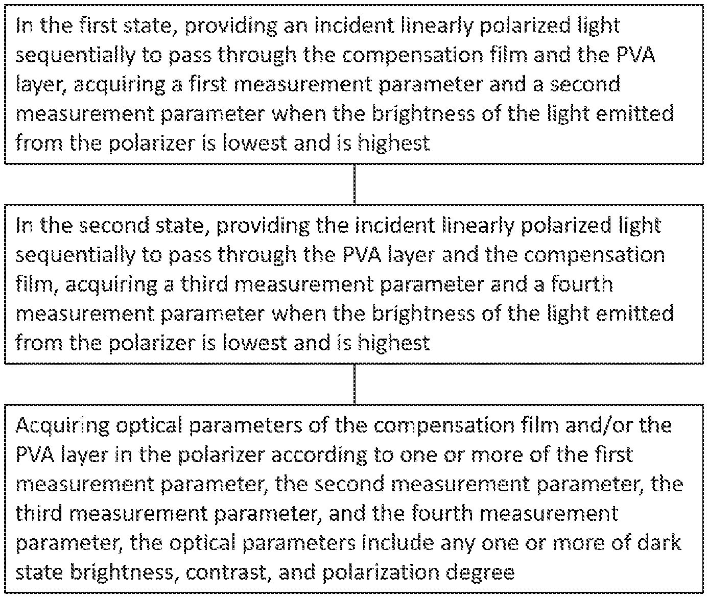
The disclosure discloses a method of measuring optical parameters of a polarizer and a measuring device. The polarizer includes a compensation film and a PVA layer. The measuring method includes the following steps. In the first state, providing an incident linearly polarized light sequentially to pass through the compensation film and the PVA layer, acquiring a first measurement parameter and a second measurement parameter when the brightness of the light emitted from the polarizer is lowest and is highest. In the second state, providing the incident linearly polarized light sequentially to pass through the PVA layer and the compensation film, acquiring a third measurement parameter and a fourth measurement parameter when the brightness of the light emitted from the polarizer is lowest and is highest; and acquiring optical parameters of the compensation film and/or the PVA layer in the polarizer according to one or more of the above measurement parameters.
| Inventors: | Hai; Bo (Huizhou Guangdong, CN) | ||||||||||
|---|---|---|---|---|---|---|---|---|---|---|---|
| Applicant: |
|
||||||||||
| Assignee: | HUIZHOU CHINA STAR OPTOELECTRONICS
TECHNOLOGY CO., LTD. (Huizhou, CN) |
||||||||||
| Family ID: | 62549276 | ||||||||||
| Appl. No.: | 15/752,425 | ||||||||||
| Filed: | January 18, 2018 | ||||||||||
| PCT Filed: | January 18, 2018 | ||||||||||
| PCT No.: | PCT/CN2018/073212 | ||||||||||
| 371(c)(1),(2),(4) Date: | February 13, 2018 | ||||||||||
| PCT Pub. No.: | WO2019/127735 | ||||||||||
| PCT Pub. Date: | July 04, 2019 |
Prior Publication Data
| Document Identifier | Publication Date | |
|---|---|---|
| US 20200132569 A1 | Apr 30, 2020 | |
Foreign Application Priority Data
| Dec 29, 2017 [CN] | 2017 1 1483432 | |||
| Current U.S. Class: | 1/1 |
| Current CPC Class: | G02B 5/3083 (20130101); G01M 11/0207 (20130101); G02F 1/1335 (20130101); G02B 5/3033 (20130101); G02B 5/3025 (20130101) |
| Current International Class: | G01J 4/00 (20060101); G01M 11/02 (20060101); G02F 1/1335 (20060101); G02B 5/30 (20060101) |
| Field of Search: | ;356/364-369 ;250/225,341.3 ;349/117,96 |
References Cited [Referenced By]
U.S. Patent Documents
| 5005977 | April 1991 | Tomoff |
| 5357342 | October 1994 | Decker |
| 6064510 | May 2000 | Gottlieb |
| 7830511 | November 2010 | Ham |
| 2006/0087653 | April 2006 | Matsumoto |
| 2010/0110432 | June 2010 | Yamagata et al. |
| 2012/0182551 | July 2012 | Lo |
| 2014/0098328 | April 2014 | Kang |
| 2018/0172887 | June 2018 | Ko |
| 1904672 | Jan 2007 | CN | |||
| 101097301 | Jan 2008 | CN | |||
| 101221038 | Jul 2008 | CN | |||
| 101369059 | Feb 2009 | CN | |||
| 101629871 | Jan 2010 | CN | |||
| 101806966 | Aug 2010 | CN | |||
| 102279094 | Dec 2011 | CN | |||
| 102589845 | Jul 2012 | CN | |||
| 104237171 | Dec 2014 | CN | |||
| 205209744 | May 2016 | CN | |||
| 105717674 | Jun 2016 | CN | |||
| 2006-242617 | Sep 2006 | JP | |||
| 2014-2019 | Jan 2014 | JP | |||
Attorney, Agent or Firm: Hemisphere Law, PLLC Ma; Zhigang
Claims
What is claimed is:
1. A method of measuring optical parameters of a polarizer, wherein the polarizer comprises a compensation film and a PVA layer, and the measuring method comprises: in a first state, providing an incident linearly polarized light to pass through the compensation film and the PVA layer sequentially, acquiring a first measurement parameter and a second measurement parameter when a brightness of light emitted from the polarizer is lowest and is highest; in a second state, providing the incident linearly polarized light to pass through the PVA layer and the compensation film sequentially, acquiring a third measurement parameter and a fourth measurement parameter when a brightness of light emitted from the polarizer is lowest and is highest; and acquiring optical parameters of the compensation film and/or the PVA layer in the polarizer according to one or more of the first measurement parameter, the second measurement parameter, the third measurement parameter, and the fourth measurement parameter, the optical parameters comprise any one or more of a dark state brightness, a contrast, and a polarization degree.
2. The measuring method according to claim 1, wherein the first measurement parameter in the first state comprises a dark state brightness Lv1, the second measurement parameter in the first state comprises a bright state brightness Lv2; the third measurement parameter in the second state comprises a dark state brightness Lv3, and the fourth measurement parameter in the second state comprises a bright state brightness Lv4.
3. The measuring method according to claim 2, wherein the optical parameters comprise any one or more of the following: the effect of the PVA layer on the dark state brightness is: Lv3; the effect of the PVA layer and the compensation film on the dark state brightness is: Lv1; the effect of the compensation film on the dark state brightness is: Lv1-Lv3; the effect of the PVA layer on the contrast is: Lv4/Lv3; the effect of the PVA layer and the compensation film on the contrast is: Lv2/Lv1; the effect of the compensation film on the contrast is: (Lv4/Lv3)-(Lv2/Lv1); the effect of the PVA layer on the polarization degree is: (Lv4-Lv3)/(Lv3+Lv4); the effect of the PVA layer and the compensation film on the polarization degree is: (Lv2-Lv1)/(Lv1+Lv2); the effect of the compensation film on the polarization degree is: (Lv4-Lv3)/(Lv3+Lv4)-(Lv2-Lv1)/(Lv1+Lv2).
4. The measuring method according to claim 2, wherein the measuring method further comprises: in the first state, acquiring a first transmission spectrum and a second transmission spectrum when a brightness of light emitted from the polarizer is lowest and is highest; and in the second state, acquiring a third transmission spectrum and a fourth transmission spectrum when a brightness of light emitted from the polarizer is lowest and is highest.
5. The measuring method according to claim 1, wherein the first measurement parameter in the first state comprises a dark state transmittance T.sub.1.perp. and the second measurement parameter in the first state comprises a bright state transmittance T.sub.2//; and the third measurement parameter in the second state comprises a dark state transmittance T.sub.3.perp., and the fourth measurement parameter in the second state comprises a bright state transmittance T.sub.4//.
6. The measuring method according to claim 5, wherein the optical parameters comprise any one or more of the following: the effect of the PVA layer on the dark state brightness is: T.sub.3.perp.; the effect of the PVA layer and the compensation film on the dark state brightness is: T.sub.1.perp.; the effect of the compensation film on the dark state brightness is: T.sub.1.perp.-T.sub.3.perp.; the effect of the PVA layer on the polarization degree is: (T.sub.4//-T.sub.3.perp.)/(T.sub.3.perp.+T.sub.4//); the effect of the PVA layer and the compensation film on the polarization degree is: (T.sub.2//-T.sub.1.perp.)/(T.sub.1.perp.+T.sub.2//); the effect of the compensation film on the polarization degree is: (T.sub.4//-T.sub.3.perp.)/(T.sub.3.perp.+T.sub.4//)- (T.sub.2//-T.sub.1.perp.)/(T.sub.1.perp.+T.sub.2//).
7. The measuring method according to claim 6, wherein the first measurement parameter in the first state comprises a dark state brightness Lv1, the second measurement parameter in the first state comprises a bright state brightness Lv2; the third measurement parameter in the second state comprises a dark state brightness Lv3, and the fourth measurement parameter in the second state comprises a bright state brightness Lv4.
8. The measuring method according to claim 7, wherein the optical parameters comprise any one or more of the following: the effect of the PVA layer on the dark state brightness is: Lv3; the effect of the PVA layer and the compensation film on the dark state brightness is: Lv1; the effect of the compensation film on the dark state brightness is: Lv1-Lv3; the effect of the PVA layer on the contrast is: Lv4/Lv3; the effect of the PVA layer and the compensation film on the contrast is: Lv2/Lv1; the effect of the compensation film on the contrast is: (Lv4/Lv3)-(Lv2/Lv1); the effect of the PVA layer on the polarization degree is: (Lv4-Lv3)/(Lv3+Lv4); the effect of the PVA layer and the compensation film on the polarization degree is: (Lv2-Lv1)/(Lv1+Lv2); the effect of the compensation film on the polarization degree is: (Lv4-Lv3)/(Lv3+Lv4)-(Lv2-Lv1)/(Lv1+Lv2).
9. The measuring method according to claim 7, wherein the measuring method further comprises: in the first state, acquiring a first transmission spectrum and a second transmission spectrum when a brightness of light emitted from the polarizer is lowest and is highest; and in the second state, acquiring a third transmission spectrum and a fourth transmission spectrum when a brightness of light emitted from the polarizer is lowest and is highest.
10. The measuring method according to claim 5, wherein the first measurement parameter in the first state comprises a dark state brightness Lv1, the second measurement parameter in the first state comprises a bright state brightness Lv2; the third measurement parameter in the second state comprises a dark state brightness Lv3, and the fourth measurement parameter in the second state comprises a bright state brightness Lv4.
11. The measuring method according to claim 10, wherein the optical parameters comprise any one or more of the following: the effect of the PVA layer on the dark state brightness is: Lv3; the effect of the PVA layer and the compensation film on the dark state brightness is: Lv1; the effect of the compensation film on the dark state brightness is: Lv1-Lv3; the effect of the PVA layer on the contrast is: Lv4/Lv3; the effect of the PVA layer and the compensation film on the contrast is: Lv2/Lv1; the effect of the compensation film on the contrast is: (Lv4/Lv3)-(Lv2/Lv1); the effect of the PVA layer on the polarization degree is: (Lv4-Lv3)/(Lv3+Lv4); the effect of the PVA layer and the compensation film on the polarization degree is: (Lv2-Lv1)/(Lv1+Lv2); the effect of the compensation film on the polarization degree is: (Lv4-Lv3)/(Lv3+Lv4)-(Lv2-Lv1)/(Lv1+Lv2).
12. The measuring method according to claim 10, wherein the measuring method further comprises: in the first state, acquiring a first transmission spectrum and a second transmission spectrum when a brightness of light emitted from the polarizer is lowest and is highest; and in the second state, acquiring a third transmission spectrum and a fourth transmission spectrum when a brightness of light emitted from the polarizer is lowest and is highest.
13. The measuring method according to claim 1, wherein the polarizer further comprises one or more of a substrate layer, a protective layer, and an adhesive layer.
Description
RELATED APPLICATIONS
The present application is a National Phase of International Application Number PCT/CN2018/073212, filed Jan. 18, 2018, and claims the priority of China Application No. 201711483432.2, filed Dec. 29, 2017.
FIELD OF THE DISCLOSURE
The present disclosure relates to a polarizer technology field, and more particularly to a method of measuring optical parameters of a polarizer and a measuring device.
BACKGROUND
High-Dynamic Range (HDR) specifications require peak brightness and dark state brightness, the actual requirements for the contrast level and contrast enhancement. Therefore, it is important to increase the contrast of the liquid crystal panel by reducing the dark state transmittance of the polarizer and increasing the polarization degree of the polarizer.
Polarizer is a multi-layer film structure, usually including the PVA layer, the compensation film, etc., affect the polarization degree of the polarizer is not only the core layer of the PVA layer, the compensation film layer will also affect the polarization degree, thus affecting the LCD panel contrast. How to sort out the impact of polarizer film is very important, and only clarify the impact of the film, in order to improve the overall structure to improve and enhance the polarization degree and panel contrast.
Commonly used LCD panel display mode is VA mode, VA display is a vertical alignment of the normally black mode, the upper and lower substrate polarizer absorption axis vertically offset. Polarizers play a crucial role throughout the display. The polarizer absorbs light in a direction perpendicular to the polarization axis and transmits only the light in the polarization axis direction to convert the natural light into linearly polarized light. Such materials are all in the form of films or plates and are therefore often referred to as polarizing films or polarizers.
The dark state brightness affected the contrast of the LCD panel greatly. Specific reference Table 1 shows:
TABLE-US-00001 TABLE 1 the effect of the dark state brightness of the LCD on the contrast Bright state 400 400 400 400 400 Dark state 0.4 0.3 0.2 0.1 0.05 Contrast 1000 1333 2000 4000 8000 Contrast 100% 133% 200% 400% 800% ratio
As can be seen from the table above, the effect of the dark state brightness on the contrast depends on the determinant factor. Therefore, it is important to improve the contrast of the liquid crystal panel by reducing the dark state brightness of the polarizer and increasing the polarization degree of the polarizer.
The main factors that affect the transmittance and the polarization degree of the dark state in the polarizer are the PVA layer and the compensation film. At present, the measurement is the measurement of the polarizer as a whole, and it is impossible to sort out which layer affects the dark state performance.
Therefore, in view of the above technical problem, it is necessary to provide a method of measuring optical parameters of a polarizer and a measuring device.
SUMMARY
In order to overcome the deficiencies of the prior art, an object of the present disclosure is to provide a method of measuring optical parameters of a polarizer and a measuring device to measure the influence of each layer of the polarizer on the optical performance of the polarizer.
In order to achieve the above object, an embodiment of the present disclosure provides the following technical solutions.
A method of measuring optical parameters of a polarizer, wherein the polarizer includes a compensation film and a PVA layer, and the measuring method includes:
in the first state, providing an incident linearly polarized light sequentially to pass through the compensation film and the PVA layer, acquiring a first measurement parameter and a second measurement parameter when the brightness of the light emitted from the polarizer is lowest and is highest; in the second state, providing the incident linearly polarized light sequentially to pass through the PVA layer and the compensation film, acquiring a third measurement parameter and a fourth measurement parameter when the brightness of the light emitted from the polarizer is lowest and is highest; and acquiring optical parameters of the compensation film and/or the PVA layer in the polarizer according to one or more of the first measurement parameter, the second measurement parameter, the third measurement parameter, and the fourth measurement parameter, the optical parameters include any one or more of dark state brightness, contrast, and polarization degree.
As a further improvement of the present disclosure, the first measurement parameter in the first state includes a dark state brightness Lv.sub.1, the second measurement parameter in the first state includes a bright state brightness Lv.sub.2; the third measurement parameter in the second state includes a dark state brightness Lv.sub.3, and the fourth measurement parameter in the second state includes a bright state brightness Lv.sub.4.
As a further improvement of the present disclosure, the optical parameters include any one or more of the following:
the effect of the PVA layer on the dark state brightness is: Lv.sub.3;
the effect of the PVA layer and the compensation film on the dark state brightness is: Lv.sub.1;
the effect of the compensation film on the dark state brightness is: Lv.sub.1-Lv.sub.3;
the effect of the PVA layer on the contrast is: Lv.sub.4/Lv.sub.3:
the effect of the PVA layer and the compensation film on the contrast is: Lv.sub.2/Lv.sub.1;
the effect of the compensation film on the contrast is: (Lv.sub.4/Lv.sub.3)-(Lv.sub.2/Lv.sub.1):
the effect of the PVA layer on the polarization degree is: (Lv.sub.4-Lv.sub.3)/(Lv.sub.3+Lv.sub.4);
the effect of the PVA layer and the compensation film on the polarization degree is: (Lv.sub.2-Lv.sub.1)/(Lv.sub.1+Lv.sub.2);
the effect of the compensation film on the polarization degree is: (Lv.sub.4-Lv.sub.3)/(Lv.sub.3+Lv.sub.4)-(Lv.sub.2-Lv.sub.1)/(Lv.sub.1+Lv.- sub.2).
As a further improvement of the present disclosure, the measuring method further includes:
in the first state, acquiring a first transmission spectrum and a second transmission spectrum when a brightness of light emitted from the polarizer is lowest and is highest; and
in the second state, acquiring a third transmission spectrum and a fourth transmission spectrum when a brightness of light emitted from the polarizer is lowest and is highest.
As a further improvement of the present disclosure, the first measurement parameter in the first state includes a dark state transmittance T.sub.1.perp. and the second measurement parameter in the first state includes a bright state transmittance T.sub.2//; and the third measurement parameter in the second state includes a dark state transmittance T.sub.3.perp., and the fourth measurement parameter in the second state includes a bright state transmittance T.sub.4//.
As a further improvement of the present disclosure, the optical parameters include any one or more of the following:
the effect of the PVA layer on the dark state brightness is: T.sub.3.perp.;
the effect of the PVA layer and the compensation film on the dark state brightness is: T.sub.1.perp.;
the effect of the compensation film on the dark state brightness is: T.sub.1.perp.-T.sub.3.perp.;
the effect of the PVA layer on the polarization degree is: (T.sub.4//-T.sub.3.perp.)/(T.sub.3.perp.+T.sub.4//);
the effect of the PVA layer and the compensation film on the polarization degree is: (T.sub.2//-T.sub.1 .perp.)/(T.sub.1.perp.+T.sub.2//);
the effect of the compensation film on the polarization degree is: (T.sub.4//-T.sub.3.perp.)(T.sub.3.perp.+T.sub.4//)- (T.sub.2//-T.sub.1.perp.)/(T.sub.1.perp.+T.sub.2//).
As a further improvement of the present disclosure, the polarizer further includes one or more of a substrate layer, a protective layer, and an adhesive layer.
The technical solution provided by another embodiment of the present disclosure is as follows.
A measuring device for optical parameters of a polarizer includes a light source arranged along an optical path, a first stage, a rotatable stage, a second stage, and a brightness meter, wherein the first stage, the rotatable stage, and the second stage are provided with through holes so that the brightness meter can receive light emitted by the light source, the first stage and the second stage are respectively used to carry a standard polarizer, and the rotatable stage is used to bear a polarizer to be measured.
As a further improvement of the present disclosure, the first stage, the rotatable stage and the second stage are respectively provided with a reference edge used for limiting the polarizer placed thereon.
As a further improvement of the present disclosure, the brightness meter is a spectrophotometer.
The measuring device of the disclosure has the advantages of simple structure, simple and easy measuring method, low cost, quickness and convenience.
The disclosure can measure the influence of the compensation film and/or the PVA layer in the polarizer on the brightness, contrast and polarization degree of the polarizer in dark state so as to improve the optical performance of the polarizer in a targeted manner.
BRIEF DESCRIPTION OF THE DRAWINGS
To describe the technical solutions in the embodiments of the present disclosure or in the prior art more clearly, the following briefly introduces the accompanying drawings required for describing the embodiments or the prior art. Apparently, the accompanying drawings in the following description show merely some embodiments of the present disclosure, and persons of ordinary skill in the art may still derive other drawings from these accompanying drawings without creative efforts.
FIG. 1 is a structural schematic diagram of the polarizer in the prior art.
FIG. 2 is a schematic structural diagram of the liquid crystal panel in the prior art.
FIG. 3 is a schematic flow chart of the method for measuring optical parameters of the polarizer of the present disclosure.
FIG. 4 and FIG. 5 are schematic diagrams of measuring the first state and the second state in Embodiment 1 of the present disclosure respectively.
FIG. 6 and FIG. 7 are schematic diagrams of measuring the first state and the second state in Embodiment 2 of the present disclosure respectively.
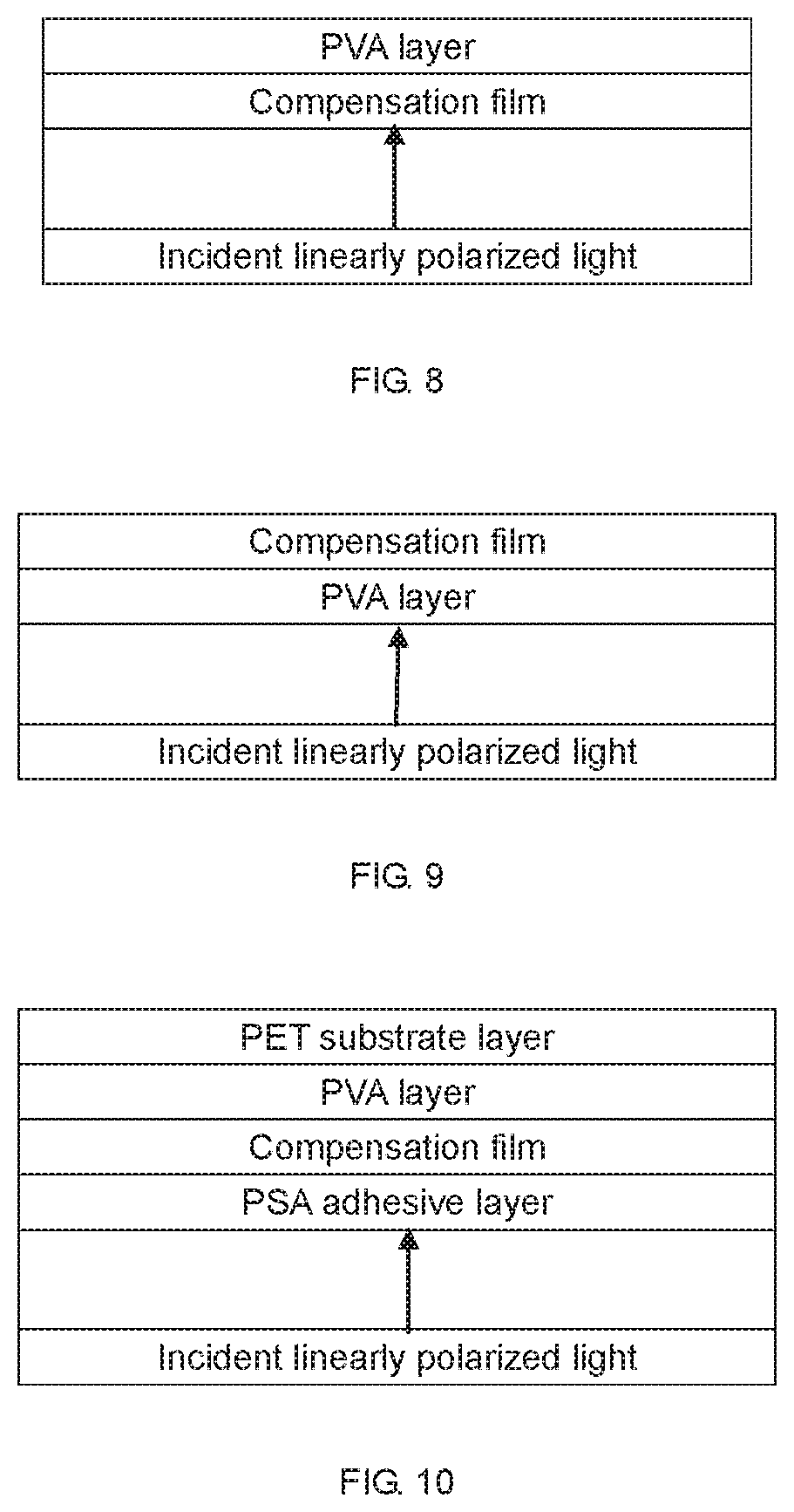
FIG. 8 and FIG. 9 are schematic diagrams of measuring the first state and the second state in Embodiment 3 of the present disclosure respectively.
FIG. 10 and FIG. 11 are schematic diagrams of measuring the first state and the second state in Embodiment 4 of the present disclosure respectively.
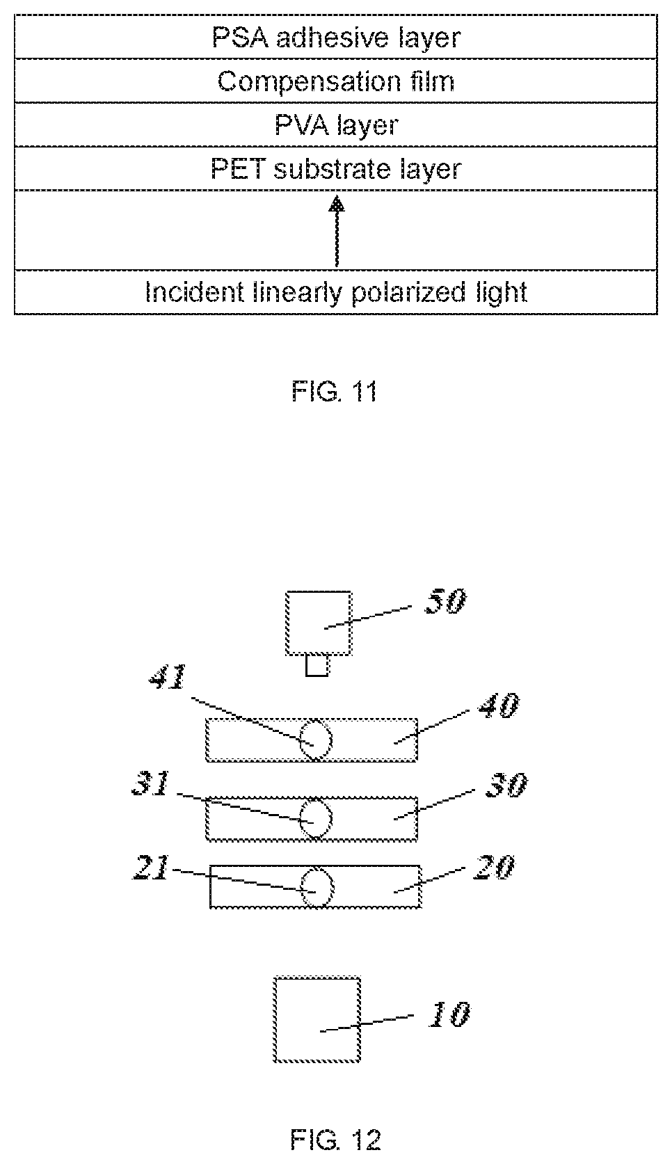
FIG. 12 is a schematic structure diagram of the polarizer optical parameter measuring device in Embodiment 7 of the present disclosure.
DETAILED DESCRIPTION OF PREFERRED EMBODIMENTS
In order to make those skilled in the art better understand the technical solutions in the present disclosure, the technical solutions in the embodiments of the present disclosure are clearly and completely described in the following with reference to the accompanying drawings in the embodiments of the present disclosure. Obviously, the described embodiments are only a part but not all of the embodiments of the present disclosure. All other embodiments obtained by a person of ordinary skill in the art based on the embodiments of the present disclosure without creative efforts shall fall within the protection scope of the present disclosure.
As used herein, terms such as "upper," "lower," etc., denoting relative positions in space, are used to describe the relationship of one element or feature to another element or feature as shown in the drawings for ease of illustration. Terms in space relative position may be intended to include different orientations of the device in use or operation other than those shown in the figures. For example, if the device in the figures is turned over, elements described as `lower` the other elements or features would be "upper" the other elements or features. Thus, the exemplary term "lower" may encompass both the directions above and below. The device may be otherwise oriented (rotated 90 degrees or at other orientations) and the spatially relative descriptors used herein interpreted accordingly.
In addition, the terms "first" and "second" are used for descriptive purposes only and are not to be construed as indicating or implying relative importance or implicitly indicating the number of indicated technical features. Thus, features defining "first" and "second" may explicitly or implicitly include at least one of the features. In the description of the present disclosure, the meaning of "plural" is at least two, for example, two, three, etc., unless expressly limited otherwise.
As shown in background of the disclosure, polarizer has a great impact on dark state, the main factors of the polarizer affect the dark state of the LCD panel are as the following.
1. The polarizability of the polarizer itself, polarizer arrangement of the uniformity and direction angle can affect the polarizer polarizability.
2. The compensation film whether the polarizer used in the VA liquid crystal display mode, if the angle between the optical axis of the compensation film and the absorption axis of the polarizer absorption axis is not 0 degrees or 90 degrees, the polarization state of linearly polarized light passing through the polarizer will be changed to elliptically polarized light so as to be transmitted from the upper polarizer to cause light leakage, and affect dark state brightness and polarization degree.
3. Whether upper and lower absorption axis is vertical.
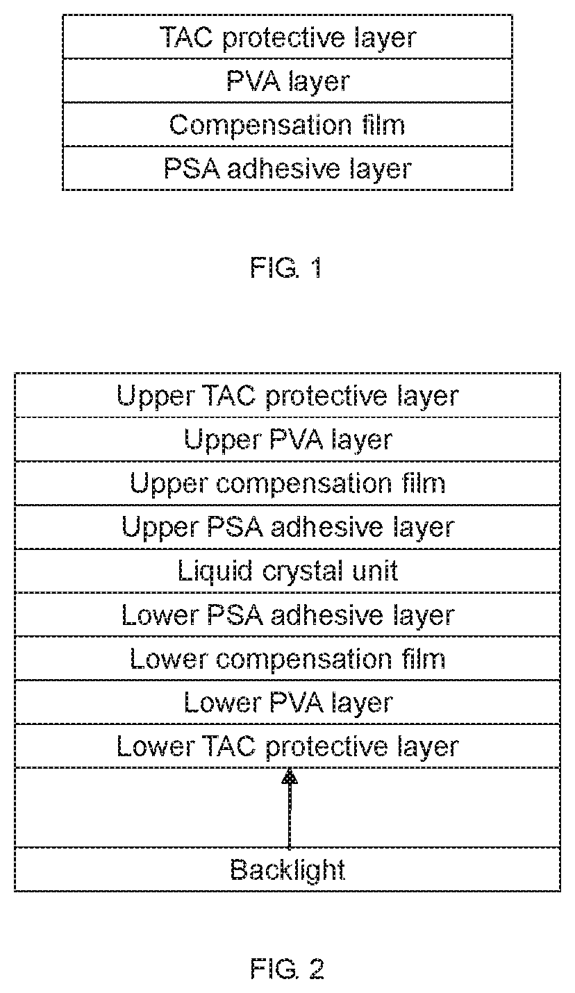
Referring to FIG. 1, FIG. 1 is a schematic structural diagram of a polarizer, which sequentially includes a PSA adhesive layer, a compensation film, a PVA layer and a TAC protective layer.
Referring to FIG. 2, FIG. 2 is a schematic structural diagram of a liquid crystal panel, which sequentially includes a backlight, a lower TAC protective layer, a lower PVA layer, a lower compensation film, a lower PSA adhesive layer, a liquid crystal unit, an upper PSA adhesive layer, an upper compensation film, an upper PVA layer, and an upper TAC protective layer. The visible light emitted by the backlight is polarized into linearly polarized light by the lower polarizer, passes through the liquid crystal unit, and then passes through the upper polarizer.
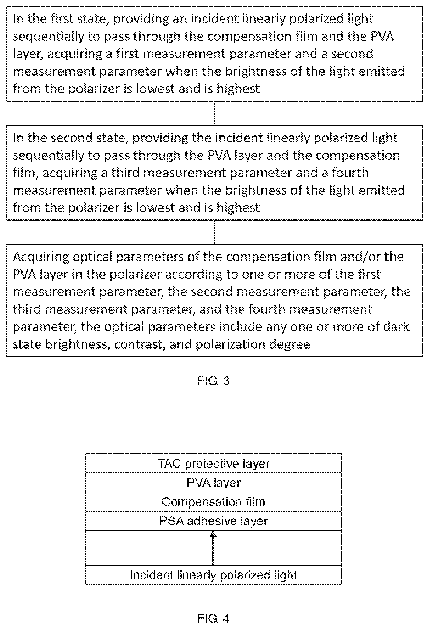
As shown in FIG. 3, the present disclosure discloses a method of measuring optical parameters of a polarizer, wherein the polarizer includes a compensation film and a PVA layer, and the measuring method includes:
in the first state, providing an incident linearly polarized light sequentially to pass through the compensation film and the PVA layer, acquiring a first measurement parameter and a second measurement parameter when the brightness of light emitted from the polarizer is lowest and is highest; in the second state, providing the incident linearly polarized light sequentially to pass through the PVA layer and the compensation film, acquiring a third measurement parameter and a fourth measurement parameter when the brightness of light emitted from the polarizer is lowest and is highest; and acquiring optical parameters of the compensation film and/or the PVA layer in the polarizer according to one or more of the first measurement parameter, the second measurement parameter, the third measurement parameter, and the fourth measurement parameter, the optical parameters include any one or more of dark state brightness, contrast, and polarization degree.
The present disclosure is described in detail below in combination with specific embodiments.
Embodiment 1
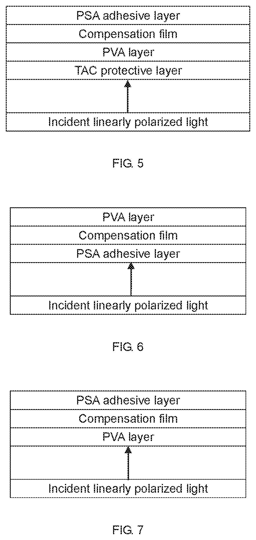
As shown in FIG. 4 and FIG. 5, the polarizer to be measured in the present embodiment includes a PSA adhesive layer, a compensation film, a PVA layer, and a TAC protective layer.
Based on the compensation film having only the inside of the PVA layer (as shown in FIG. 4), it is possible to affect the dark state brightness and the polarization degree by changing the polarization state of the incident linearly polarized light, while the outside of the PVA layer (shown in FIG. 5), it does not affect the dark state brightness and polarizer polarization, according to the principle, a measurement method can be designed to detect the effect of the compensation film and/or the PVA layer on the darkness and the polarization degree of the dark state.
As shown in FIG. 4, in the first state, providing an incident linearly polarized light sequentially to pass through the compensation film and the PVA layer, acquiring a first measurement parameter and a second measurement parameter when the brightness of light emitted from the polarizer is lowest and is highest.
As shown in FIG. 5, in the second state, providing the incident linearly polarized light sequentially to pass through the PVA layer and the compensation film, acquiring a third measurement parameter and a fourth measurement parameter when the brightness of light emitted from the polarizer is lowest and is highest.
Acquiring optical parameters of the compensation film and/or the PVA layer in the polarizer according to one or more of the first measurement parameter, the second measurement parameter, the third measurement parameter, and the fourth measurement parameter, the optical parameters include any one or more of dark state brightness, contrast, and polarization degree.
In the first state, the incident linearly polarized light passes through the compensation film and then passes through the PVA layer. When passing through the compensation film, if the angle between the optical axis of the compensation film and the absorption axis of the PVA layer is not 0 or 90 degrees, the incident linearly polarized light will become elliptically polarized light, then there will be light leakage through the PVA layer, affecting the dark state brightness and the polarization degree.
In the second state, the incident linearly polarized light passes through the PVA layer first and then passes through the compensation film. When passing through the PVA layer, the incident linearly polarized light or the linearly polarized light passes through the compensation film, even if the optical axis and the absorption axis of the PVA layer have an included angle of 0 or 90 degrees, the incident linearly polarized light will become elliptically polarized light, does not affect the light intensity, and does not affect the dark state brightness and the polarization degree.
Through the above measurement results under the two states, the effect of the compensation film and the PVA layer on dark state brightness, contrast, and polarization degree can be calculated.
Embodiment 2
As shown in FIG. 6 and FIG. 7, The polarizer to be measured in the present embodiment includes a PSA adhesive layer, a compensation film, and a PVA layer. Compared with Embodiment 1, the polarizer in this embodiment removes the TAC protective layer, which can improve the measurement accuracy.
The measuring method is exactly the same as that in Embodiment 1, and details are not described herein again.
Embodiment 3
As shown in FIG. 8 and FIG. 9, the polarizer to be measured in the embodiment includes a compensation film and a PVA layer. Compared with Example 1, the polarizer in this embodiment removes the TAC protective layer and the PSA adhesive layer, which can improve the measurement accuracy.
The measuring method is exactly the same as that in Embodiment 1, and details are not described herein again.
Embodiment 4
As shown in FIG. 10 and FIG. 11, the polarizer to be measured in this embodiment includes a PSA adhesive layer, a compensation film, a PVA layer, and a PET substrate layer.
The measuring method is exactly the same as that in Embodiment 1, and details are not described herein again.
Embodiment 5
The method for measuring optical parameters of a polarizer of the present embodiment includes that: the polarizer includes a compensation film and a PVA layer; and the measuring method includes:
As shown in FIG. 8, in the first state, providing an incident linearly polarized light sequentially to pass through the compensation film and the PVA layer, acquiring a first measurement parameter and a second measurement parameter when the brightness of light emitted from the polarizer is lowest and is highest. The first measurement parameter includes a dark state brightness Lv.sub.1, the second measurement parameter includes a bright state brightness Lv.sub.2.
As shown in FIG. 9, in the second state, providing the incident linearly polarized light sequentially to pass through the PVA layer and the compensation film, acquiring a third measurement parameter and a fourth measurement parameter when the brightness of light emitted from the polarizer is lowest and is highest. The third measurement parameter includes a dark state brightness Lv.sub.3, the fourth measurement parameter includes a bright state brightness Lv.sub.4.
Acquiring optical parameters of the compensation film and/or the PVA layer in the polarizer according to one or more of the first measurement parameter, the second measurement parameter, the third measurement parameter, and the fourth measurement parameter, the optical parameters include any one or more of the following:
the effect of the PVA layer on the dark state brightness is: Lv.sub.3;
the effect of the PVA layer and the compensation film on the dark state brightness is: Lv.sub.1;
the effect of the compensation film on the dark state brightness is: Lv.sub.1-Lv.sub.3;
the effect of the PVA layer on the contrast is: Lv.sub.4/Lv.sub.3;
the effect of the PVA layer and the compensation film on the contrast is: Lv.sub.2/Lv.sub.1;
the effect of the compensation film on the contrast is: (Lv.sub.4/Lv.sub.3)-(Lv.sub.2/Lv.sub.1);
the effect of the PVA layer on the polarization degree is: (Lv.sub.4-Lv.sub.3)/(Lv.sub.3+Lv.sub.4);
the effect of the PVA layer and the compensation film on the polarization degree is: (Lv.sub.2-Lv.sub.1)/(Lv.sub.1+Lv.sub.2);
the effect of the compensation film on the polarization degree is: (Lv.sub.4-Lv.sub.3)/(Lv.sub.3+Lv.sub.4)-(Lv.sub.2-Lv.sub.1)/(Lv.sub.1+Lv.- sub.2).
Further, the measuring method in this embodiment may further includes:
in the first state, acquiring a first transmission spectrum and a second transmission spectrum when a brightness of light emitted from the polarizer is lowest and is highest; and in the second state, acquiring a third transmission spectrum and a fourth transmission spectrum when a brightness of light emitted from the polarizer is lowest and is highest.
Through the measurement of the penetration spectrum, the effect of the specific wavelength on the polarizer optical parameters can be analyzed.
Embodiment 6
The method for measuring optical parameters of a polarizer of the present embodiment includes that: the polarizer includes a compensation film and a PVA layer; and the measuring method includes the follows.
As shown in FIG. 8, in the first state, providing an incident linearly polarized light sequentially to pass through the compensation film and the PVA layer, acquiring a first measurement parameter and a second measurement parameter when the brightness of light emitted from the polarizer is lowest and is highest. The first measurement parameter includes a dark state transmittance T.sub.1.perp. and the second measurement parameter includes a bright state transmittance T.sub.2//.
As shown in FIG. 9, in the second state, providing the incident linearly polarized light sequentially to pass through the PVA layer and the compensation film, acquiring a third measurement parameter and a fourth measurement parameter when the brightness of light emitted from the polarizer is lowest and is highest. The third measurement parameter includes a dark state transmittance T.sub.3.perp. and the fourth measurement parameter includes a bright state transmittance T.sub.4//.
Acquiring optical parameters of the compensation film and/or the PVA layer in the polarizer according to one or more of the first measurement parameter, the second measurement parameter, the third measurement parameter, and the fourth measurement parameter, the optical parameters include any one or more of the following:
the effect of the PVA layer on the dark state brightness is: T.sub.3.perp.;
the effect of the PVA layer and the compensation film on the dark state brightness is: T.sub.1.perp.;
the effect of the compensation film on the dark state brightness is: T.sub.1.perp.-T.sub.3.perp.;
the effect of the PVA layer on the polarization degree is: (T.sub.4//-T.sub.3.perp.)/(T.sub.3.perp.+T.sub.4//);
the effect of the PVA layer and the compensation film on the polarization degree is: (T.sub.2//-T.sub.1.perp.)/(T.sub.1.perp.+T.sub.2//);
the effect of the compensation film on the polarization degree is: (T.sub.4//-T.sub.3.perp.)/(T.sub.3.perp.+T.sub.4//)- (T.sub.2//-T.sub.1.perp.)/(T.sub.1.perp.+T.sub.2//).
Embodiment 7
As shown in FIG. 12, in this embodiment, the polarizer optical parameter measurement device includes a light source 10, a first stage 20, a rotatable stage 30, a second stage 40, and a brightness meter 50 arranged along an optical path.
The first stage 20, the rotatable stage 30, and the second stage 40 are respectively provided with through holes 21, 31, and 41, so that the brightness meter 50 can receive the light emitted by the light source 10. The first stage 20 and the second stage 40 are respectively used to carry a standard polarizer. The rotatable stage 30 is used to carry the polarizer to be measured, and the three stages need to be aligned, that is, the angles are the same.
The first stage 20, the rotatable stage 30 and the second stage 40 are respectively provided with a reference edge for limiting the polarizer placed thereon. Here, the stage is square or rectangular, four sides of the stage as the reference side. In this way, the standard polarizer and the polarizer to be measured can be placed with the reference side of the polarizer in alignment with the reference side of the stage.
The rotatable stage 30 is rotatable, connected with the servo motor, and precisely controlled by a servo motor. The rotation precision can reach 0.01 degree and the rotation angle can be 0-360-degree rotation.
Brightness meter requires high-precision measurement equipment, where the choice of spectrophotometer measurements, such as CS2000, CS2000A and SR-UL2 and other spectrophotometers, along with spectral measurement.
Embodiment 8
Using the measuring apparatus in Embodiment 7, three different polarizers were measured by the method in Embodiment 6 and the results are shown in Table 2-4.
TABLE-US-00002 TABLE 2 Common optical parameters of PVA layer and compensation film Linear polarized light is incident First Second Third piece piece piece Parallel penetration rate 36.6 36.6 36.6 Vertical penetration rate 0.0016 0.0016 0.0018 Polarization degree 99.9956 99.9955 99.9950 Contrast 23161 22588 19978
TABLE-US-00003 TABLE 3 Optical parameters of PVA layer Linear polarized light incident back First Second Third piece piece piece Parallel penetration rate 36.6 36.6 36.5 Vertical penetration rate 0.0013 0.0013 0.0012 Polarization degree 99.9965 99.9965 99.9968 Contrast 28619 29141 31603
TABLE-US-00004 TABLE 4 Optical parameters of compensation film Second Third First piece piece piece Vertical penetration rate -0.0003 -0.0004 -0.0007 Polarization degree 0.0008 0.0010 0.0019 Contrast 5458 6554 11625
Through the above parameters, the PVA layer dark state performance of the three-piece polarizer is more consistent, the third piece of the compensation film on the dark state of the polarizer most affected.
It can be seen from the above technical solutions that the present disclosure has the following beneficial effects.
The measuring device of the disclosure has the advantages of simple structure, simple and easy measuring method, low cost, quickness and convenience.
The disclosure can measure the influence of the compensation film and/or the PVA layer in the polarizer on the brightness, contrast and polarization degree of the polarizer in dark state so as to improve the optical performance of the polarizer in a targeted manner.
It will be apparent to those skilled in the art that the disclosure is not limited to the details of the foregoing exemplary embodiments, but that the present disclosure may be embodied in other specific forms without departing from the spirit or essential characteristics of the disclosure. Therefore, the present embodiments are to be considered in all respects as illustrative and not restrictive, the scope of the disclosure being defined by the appended claims rather than the foregoing description. It is therefore intended to include in the disclosure all the changes which come within the meaning and range of equivalency of the claims. Any reference signs in the claims should not be construed as limiting the claim involved.
In addition, it should be understood that, although the specification is described according to the embodiments, not every embodiment includes only one independent technical solution. This description in the specification is merely for the sake of clarity. Those skilled in the art should take the description as a whole and the technical solutions in the embodiments may also be combined as appropriate to form other embodiments that can be understood by those skilled in the art.
* * * * *
D00000
D00001
D00002
D00003
D00004
D00005
XML
uspto.report is an independent third-party trademark research tool that is not affiliated, endorsed, or sponsored by the United States Patent and Trademark Office (USPTO) or any other governmental organization. The information provided by uspto.report is based on publicly available data at the time of writing and is intended for informational purposes only.
While we strive to provide accurate and up-to-date information, we do not guarantee the accuracy, completeness, reliability, or suitability of the information displayed on this site. The use of this site is at your own risk. Any reliance you place on such information is therefore strictly at your own risk.
All official trademark data, including owner information, should be verified by visiting the official USPTO website at www.uspto.gov. This site is not intended to replace professional legal advice and should not be used as a substitute for consulting with a legal professional who is knowledgeable about trademark law.