Drill apparatus and surgical fixation devices and methods for using the same
Frey , et al. A
U.S. patent number 10,743,890 [Application Number 15/675,378] was granted by the patent office on 2020-08-18 for drill apparatus and surgical fixation devices and methods for using the same. This patent grant is currently assigned to MIGHTY OAK MEDICAL, INC.. The grantee listed for this patent is Mighty Oak Medical, Inc.. Invention is credited to George Frey, Sean Starkman.


View All Diagrams
| United States Patent | 10,743,890 |
| Frey , et al. | August 18, 2020 |
Drill apparatus and surgical fixation devices and methods for using the same
Abstract
The present application relates to systems, methods, and devices for performing drilling operations, such as in a surgical setting. The embodiments disclosed herein include handheld drill apparatus configured to be used with guides for completing a specific operation. The drill apparatus is capable of receiving instructions either through programming, from a memory device, or from scanning a device located on an external item, such as a guide.
| Inventors: | Frey; George (Englewood, CO), Starkman; Sean (Littleton, CO) | ||||||||||
|---|---|---|---|---|---|---|---|---|---|---|---|
| Applicant: |
|
||||||||||
| Assignee: | MIGHTY OAK MEDICAL, INC.
(Englewood, CO) |
||||||||||
| Family ID: | 61160630 | ||||||||||
| Appl. No.: | 15/675,378 | ||||||||||
| Filed: | August 11, 2017 |
Prior Publication Data
| Document Identifier | Publication Date | |
|---|---|---|
| US 20180042619 A1 | Feb 15, 2018 | |
Related U.S. Patent Documents
| Application Number | Filing Date | Patent Number | Issue Date | ||
|---|---|---|---|---|---|
| 15416975 | Jan 26, 2017 | 9987024 | |||
| 62373855 | Aug 11, 2016 | ||||
| Current U.S. Class: | 1/1 |
| Current CPC Class: | A61B 17/1671 (20130101); A61F 2/4611 (20130101); A61F 2/44 (20130101); A61B 17/1757 (20130101); G09B 23/30 (20130101); A61B 34/00 (20160201); A61B 17/1615 (20130101); A61B 17/151 (20130101); A61B 17/1626 (20130101); A61B 2017/00199 (20130101); A61B 2017/00398 (20130101); A61F 2310/00059 (20130101); A61B 17/1622 (20130101); A61B 34/20 (20160201); A61B 2017/00017 (20130101); A61B 2034/107 (20160201); A61B 2017/568 (20130101); A61F 2310/00017 (20130101); A61B 2017/3447 (20130101); A61B 34/25 (20160201); A61F 2310/00029 (20130101); A61B 90/96 (20160201); A61B 90/98 (20160201); A61F 2/4405 (20130101); A61B 2090/067 (20160201); A61F 2/30965 (20130101); A61F 2002/30948 (20130101); A61F 2002/4687 (20130101); B33Y 10/00 (20141201); A61F 2002/30952 (20130101); B33Y 80/00 (20141201); A61F 2310/00047 (20130101); A61F 2310/00023 (20130101); A61B 2017/00123 (20130101); A61B 2017/00734 (20130101); A61B 2090/061 (20160201) |
| Current International Class: | A61B 17/16 (20060101); A61B 17/17 (20060101); A61B 17/15 (20060101); G09B 23/30 (20060101); A61F 2/46 (20060101); A61F 2/44 (20060101); A61B 34/00 (20160101); A61B 17/00 (20060101); A61B 17/34 (20060101); A61B 90/00 (20160101); A61F 2/30 (20060101); A61B 17/56 (20060101); A61B 34/10 (20160101); A61B 34/20 (20160101); B33Y 80/00 (20150101); B33Y 10/00 (20150101); A61B 90/98 (20160101); A61B 90/96 (20160101) |
References Cited [Referenced By]
U.S. Patent Documents
| 3151392 | October 1964 | Chambers |
| 5092866 | March 1992 | Breard et al. |
| 5129904 | July 1992 | Illi |
| 5201734 | April 1993 | Cozard et al. |
| 5291901 | March 1994 | Graf |
| 5360448 | November 1994 | Thramann |
| 5387213 | January 1995 | Breard et al. |
| D359557 | June 1995 | Hayes |
| 5490409 | February 1996 | Weber |
| 5527312 | June 1996 | Ray |
| 5562737 | October 1996 | Graf |
| 5569246 | October 1996 | Ojima et al. |
| 5591233 | January 1997 | Kelman et al. |
| 5725581 | March 1998 | Branemark |
| D403066 | December 1998 | DeFonzo |
| 5865846 | February 1999 | Bryan et al. |
| RE36221 | June 1999 | Breard et al. |
| D412032 | July 1999 | Mikula-Curtis et al. |
| 5961516 | October 1999 | Graf |
| 5993453 | November 1999 | Bullara et al. |
| 6006581 | December 1999 | Holmes |
| D420132 | February 2000 | Bucholz et al. |
| 6030401 | February 2000 | Marino |
| 6035691 | March 2000 | Lin et al. |
| 6048343 | April 2000 | Mathis et al. |
| 6063088 | May 2000 | Winslow |
| D428989 | August 2000 | Segemark et al. |
| 6113602 | September 2000 | Sand |
| 6142998 | November 2000 | Smith et al. |
| 6221077 | April 2001 | Rinner et al. |
| 6290724 | September 2001 | Marino |
| 6309395 | October 2001 | Smith et al. |
| 6328738 | December 2001 | Suddaby |
| 6364880 | April 2002 | Michelson |
| 6402750 | June 2002 | Atkinson et al. |
| 6445211 | September 2002 | Saripella |
| 6644087 | November 2003 | Ralph et al. |
| 6663633 | December 2003 | Pierson, III |
| 6711432 | March 2004 | Krause et al. |
| 6719795 | April 2004 | Cornwall et al. |
| 6755839 | June 2004 | Van Hoeck et al. |
| 6835207 | December 2004 | Zacouto et al. |
| 7014640 | March 2006 | Kemppanien et al. |
| 7025769 | April 2006 | Ferree |
| 7066957 | June 2006 | Graf |
| 7077864 | July 2006 | Bryd, III et al. |
| D532515 | November 2006 | Buttler et al. |
| D533664 | December 2006 | Butler et al. |
| 7207992 | April 2007 | Ritland |
| 7235076 | June 2007 | Pacheco |
| 7288093 | October 2007 | Michelson |
| 7291150 | November 2007 | Graf |
| 7341590 | March 2008 | Ferree |
| 7387643 | June 2008 | Michelson |
| 7406775 | August 2008 | Funk et al. |
| 7454939 | November 2008 | Garner et al. |
| 7491180 | February 2009 | Pacheco |
| 7537664 | May 2009 | Oneill et al. |
| 7559931 | July 2009 | Stone |
| 7578851 | August 2009 | Dong et al. |
| 7623902 | November 2009 | Pacheco |
| D606195 | December 2009 | Eisen et al. |
| 7658610 | February 2010 | Knopp |
| D618796 | June 2010 | Cantu et al. |
| 7844356 | November 2010 | Matov et al. |
| 7854752 | December 2010 | Colleran et al. |
| 7955355 | June 2011 | Cin |
| 7957824 | June 2011 | Boronvinskih et al. |
| 7957831 | June 2011 | Isaacs |
| 7967868 | June 2011 | White et al. |
| 8057482 | November 2011 | Stone et al. |
| 8070752 | December 2011 | Metzger et al. |
| 8092465 | January 2012 | Metzger et al. |
| 8118815 | February 2012 | van der Walt |
| 8159753 | April 2012 | Ojeda et al. |
| 8167884 | May 2012 | Pacheco |
| 8175683 | May 2012 | Roose |
| 8206396 | June 2012 | Trabish |
| 8214014 | July 2012 | Pacheco |
| 8236006 | August 2012 | Hamada |
| 8241293 | August 2012 | Stone et al. |
| 8257083 | September 2012 | Berckmans et al. |
| D669176 | October 2012 | Frey |
| D669984 | October 2012 | Cheney et al. |
| 8277461 | October 2012 | Pacheco |
| 8282646 | October 2012 | Schoenefeld et al. |
| 8292967 | October 2012 | Brown et al. |
| 8298235 | October 2012 | Grinberg et al. |
| 8298237 | October 2012 | Schoenefeld et al. |
| 8298242 | October 2012 | Justis et al. |
| D672038 | December 2012 | Frey |
| 8323322 | December 2012 | Dawson et al. |
| 8357111 | January 2013 | Caillouette et al. |
| 8377066 | February 2013 | Katrana et al. |
| 8407067 | March 2013 | Uthgenannt et al. |
| 8419740 | April 2013 | Aram et al. |
| D685087 | June 2013 | Voic |
| 8460303 | June 2013 | Park |
| 8475505 | July 2013 | Nebosky et al. |
| 8480679 | July 2013 | Park et al. |
| 8535387 | September 2013 | Meridew et al. |
| 8540719 | September 2013 | Peukert et al. |
| 8545509 | October 2013 | Park et al. |
| 8549888 | October 2013 | Isaacs |
| 8568487 | October 2013 | Witt et al. |
| 8591516 | November 2013 | Metzger et al. |
| 8603180 | December 2013 | White et al. |
| 8607603 | December 2013 | Justis et al. |
| 8608748 | December 2013 | Metzger et al. |
| 8608749 | December 2013 | Meridew et al. |
| 8632547 | January 2014 | Maxson et al. |
| 8668700 | March 2014 | Catanzarite |
| 8671572 | March 2014 | Schlottig et al. |
| D705929 | May 2014 | Frey |
| 8721651 | May 2014 | Loke et al. |
| 8758357 | June 2014 | Frey |
| 8808302 | August 2014 | Roose et al. |
| 8808303 | August 2014 | Stemniski et al. |
| 8821506 | September 2014 | Mitchell |
| 8858561 | October 2014 | White et al. |
| 8864769 | October 2014 | Stone et al. |
| 8870889 | October 2014 | Frey |
| D718862 | December 2014 | Matheny |
| D718863 | December 2014 | Matheny |
| D718864 | December 2014 | Matheny |
| 8900279 | December 2014 | Assell et al. |
| 8979749 | March 2015 | Gorek et al. |
| 8979911 | March 2015 | Martineau et al. |
| 8992538 | March 2015 | Keefer |
| D726914 | April 2015 | Matheny |
| 9017412 | April 2015 | Wolters et al. |
| 9044285 | June 2015 | Harper |
| 9066727 | June 2015 | Catanzarite et al. |
| 9066816 | June 2015 | Allard et al. |
| 9113971 | August 2015 | Metzger et al. |
| D738498 | September 2015 | Frey et al. |
| 9138325 | September 2015 | Mouw |
| 9173661 | November 2015 | Metzger et al. |
| D745671 | December 2015 | Frey et al. |
| D745672 | December 2015 | Frey et al. |
| D745673 | December 2015 | Frey et al. |
| 9198678 | December 2015 | Frey et al. |
| 9216045 | December 2015 | Martineau et al. |
| 9451973 | September 2016 | Heilman et al. |
| 9456901 | October 2016 | Jones et al. |
| D775335 | December 2016 | Frey et al. |
| 9642633 | May 2017 | Frey et al. |
| 9649160 | May 2017 | van der Walt et al. |
| 9662157 | May 2017 | Schneider et al. |
| 9675400 | June 2017 | Katrana et al. |
| 9737339 | August 2017 | Copp et al. |
| 9814497 | November 2017 | Al-Habib et al. |
| 9826991 | November 2017 | Kaiser et al. |
| 9839448 | December 2017 | Reckling et al. |
| 9848922 | December 2017 | Tohmeh et al. |
| 9913669 | March 2018 | Scholl et al. |
| 9949843 | April 2018 | Reiley et al. |
| 9968408 | May 2018 | Casey et al. |
| 9987024 | June 2018 | Frey et al. |
| 10085784 | October 2018 | Ono et al. |
| 10166033 | January 2019 | Reiley et al. |
| 2004/0097925 | May 2004 | Boehm et al. |
| 2004/0144149 | July 2004 | Strippgen et al. |
| 2004/0243481 | December 2004 | Bradbury et al. |
| 2004/0267260 | December 2004 | Mack et al. |
| 2005/0085815 | April 2005 | Harms et al. |
| 2005/0148843 | July 2005 | Roose |
| 2005/0177156 | August 2005 | Timm et al. |
| 2005/0203514 | September 2005 | Jahng et al. |
| 2005/0203519 | September 2005 | Harms et al. |
| 2005/0262911 | December 2005 | Dankowicz et al. |
| 2005/0288672 | December 2005 | Ferree |
| 2006/0036323 | February 2006 | Carl et al. |
| 2006/0058792 | March 2006 | Hynes |
| 2006/0084986 | April 2006 | Grinberg et al. |
| 2006/0095044 | May 2006 | Grady, Jr. et al. |
| 2006/0149375 | July 2006 | Yuan et al. |
| 2006/0241385 | October 2006 | Dietz |
| 2006/0264935 | November 2006 | White |
| 2007/0088359 | April 2007 | Woods et al. |
| 2007/0093813 | April 2007 | Callahan, II et al. |
| 2007/0093832 | April 2007 | Abdelgany |
| 2007/0100341 | May 2007 | Reglos et al. |
| 2007/0161985 | July 2007 | Demakus et al. |
| 2007/0198014 | August 2007 | Graf et al. |
| 2007/0227216 | October 2007 | Schalliol |
| 2007/0288011 | December 2007 | Logan |
| 2007/0288030 | December 2007 | Metzger et al. |
| 2008/0086127 | April 2008 | Patterson et al. |
| 2008/0114370 | May 2008 | Shoenefeld |
| 2008/0161815 | July 2008 | Shoenefeld et al. |
| 2008/0183214 | July 2008 | Copp et al. |
| 2008/0255564 | October 2008 | Michelson |
| 2008/0257363 | October 2008 | Schoenefeld et al. |
| 2008/0275452 | November 2008 | Lang et al. |
| 2008/0306552 | December 2008 | Winslow |
| 2008/0312659 | December 2008 | Metzger et al. |
| 2008/0319491 | December 2008 | Schoenefeld |
| 2009/0076555 | March 2009 | Lowry et al. |
| 2009/0087276 | April 2009 | Rose |
| 2009/0088674 | April 2009 | Caillouette et al. |
| 2009/0088761 | April 2009 | Roose et al. |
| 2009/0088763 | April 2009 | Aram et al. |
| 2009/0093816 | April 2009 | Roose et al. |
| 2009/0099567 | April 2009 | Zajac |
| 2009/0105760 | April 2009 | Frey |
| 2009/0110498 | April 2009 | Park |
| 2009/0138020 | May 2009 | Park et al. |
| 2009/0187194 | July 2009 | Hamada |
| 2009/0198277 | August 2009 | Gordon et al. |
| 2009/0254093 | October 2009 | White et al. |
| 2009/0270868 | October 2009 | Park et al. |
| 2009/0326537 | December 2009 | Anderson |
| 2010/0016984 | January 2010 | Trabish |
| 2010/0049195 | February 2010 | Park et al. |
| 2010/0082035 | April 2010 | Keefer |
| 2010/0087829 | April 2010 | Metzger et al. |
| 2010/0100193 | April 2010 | White |
| 2010/0152782 | June 2010 | Stone et al. |
| 2010/0191244 | July 2010 | White et al. |
| 2010/0217270 | August 2010 | Polinski et al. |
| 2010/0217336 | August 2010 | Crawford et al. |
| 2010/0305700 | December 2010 | Ben-Arye et al. |
| 2010/0324692 | December 2010 | Uthgenannt et al. |
| 2011/0015636 | January 2011 | Katrana et al. |
| 2011/0015639 | January 2011 | Metzger et al. |
| 2011/0046735 | February 2011 | Metzger et al. |
| 2011/0054478 | March 2011 | Vanasse et al. |
| 2011/0071533 | March 2011 | Metzger et al. |
| 2011/0093023 | April 2011 | Lee et al. |
| 2011/0093086 | April 2011 | Witt et al. |
| 2011/0160736 | June 2011 | Meridew et al. |
| 2011/0160867 | June 2011 | Meridew et al. |
| 2011/0166578 | July 2011 | Stone et al. |
| 2011/0184419 | July 2011 | Meridew et al. |
| 2011/0184526 | July 2011 | White et al. |
| 2011/0190899 | August 2011 | Pierce et al. |
| 2011/0213376 | September 2011 | Maxson et al. |
| 2011/0218545 | September 2011 | Catanzarite et al. |
| 2011/0224674 | September 2011 | White et al. |
| 2011/0288433 | November 2011 | Kelleher et al. |
| 2012/0041445 | February 2012 | Roose et al. |
| 2012/0130434 | May 2012 | Stemniski et al. |
| 2012/0150243 | June 2012 | Crawford et al. |
| 2012/0179259 | July 2012 | McDonough et al. |
| 2012/0215315 | August 2012 | Hochschuler et al. |
| 2012/0245587 | September 2012 | Fang |
| 2013/0006251 | January 2013 | Aram et al. |
| 2013/0053854 | February 2013 | Schoenefeld et al. |
| 2013/0060278 | March 2013 | Bozung |
| 2013/0110174 | May 2013 | Marik |
| 2013/0123850 | May 2013 | Schoenefeld et al. |
| 2014/0137618 | May 2014 | Isaacs |
| 2014/0379032 | December 2014 | Hennard |
| 2015/0047410 | February 2015 | Petit et al. |
| 2015/0119939 | April 2015 | Frey et al. |
| 2015/0127053 | May 2015 | Maruenda Paulino et al. |
| 2015/0297249 | October 2015 | Catanzarite |
| 2016/0030067 | February 2016 | Frey et al. |
| 2016/0270802 | September 2016 | Fang et al. |
| 2017/0215857 | August 2017 | D'Urso |
| 2736525 | Mar 2010 | CA | |||
| 2862341 | Aug 2013 | CA | |||
| 201275138 | Jul 2009 | CN | |||
| 201404283 | Feb 2010 | CN | |||
| 101390773 | Nov 2010 | CN | |||
| 101953713 | Jan 2011 | CN | |||
| 104306061 | Jan 2015 | CN | |||
| 105078563 | Nov 2015 | CN | |||
| 106175911 | Dec 2016 | CN | |||
| 104224306 | Aug 2017 | CN | |||
| 102013110699 | Apr 2015 | DE | |||
| 202014011170 | Apr 2018 | DE | |||
| 2168507 | Mar 2010 | EP | |||
| 2957244 | Dec 2015 | EP | |||
| 2749235 | Aug 2017 | EP | |||
| 3381382 | Oct 2018 | EP | |||
| 3012030 | Dec 2015 | FR | |||
| 3023655 | Apr 2018 | FR | |||
| 2447702 | Sep 2008 | GB | |||
| 10071157 | Mar 1998 | JP | |||
| 2002531214 | Sep 2002 | JP | |||
| 2005118569 | May 2005 | JP | |||
| 2006528533 | Dec 2006 | JP | |||
| 2007502692 | Feb 2007 | JP | |||
| 2007510482 | Apr 2007 | JP | |||
| 2012143379 | Aug 2012 | JP | |||
| WO2004071314 | Aug 2004 | WO | |||
| 200503710 | Apr 2005 | WO | |||
| 2006039266 | Apr 2006 | WO | |||
| 2006066053 | Jun 2006 | WO | |||
| 2006079531 | Aug 2006 | WO | |||
| 2007037920 | Apr 2007 | WO | |||
| 2007145937 | Dec 2007 | WO | |||
| 2008027549 | Mar 2008 | WO | |||
| WO2009004625 | Jan 2009 | WO | |||
| 2009035358 | Mar 2009 | WO | |||
| WO2006017641 | Apr 2009 | WO | |||
| WO2008157412 | Apr 2009 | WO | |||
| 2009129063 | Oct 2009 | WO | |||
| 2009105106 | Dec 2009 | WO | |||
| WO2010033431 | Mar 2010 | WO | |||
| 2010148103 | Dec 2010 | WO | |||
| 2011041398 | Apr 2011 | WO | |||
| 2011080260 | Jul 2011 | WO | |||
| 2011106711 | Sep 2011 | WO | |||
| 2011109260 | Sep 2011 | WO | |||
| WO2012082164 | Jun 2012 | WO | |||
| 2012152900 | Nov 2012 | WO | |||
| 2013041618 | Mar 2013 | WO | |||
| WO2013041618 | Mar 2013 | WO | |||
| 2013104682 | Jul 2013 | WO | |||
| WO2013169674 | Nov 2013 | WO | |||
| WO2013173700 | Nov 2013 | WO | |||
| WO2014070889 | May 2014 | WO | |||
| 2014088801 | Jun 2014 | WO | |||
| WO2014090908 | Jun 2014 | WO | |||
| WO2014095853 | Jun 2014 | WO | |||
| 2014143762 | Sep 2014 | WO | |||
| WO2014198279 | Dec 2014 | WO | |||
| WO2016148675 | Sep 2016 | WO | |||
Other References
|
"Calculator for Designing Compression Springs," eFunda, Inc., first published online Sep. 25, 2000 per Wayback Machine, 2 pages, [retrieved from: http://www.efunda.com/designstandards/springs/calc_comp_designer.cf- m]. cited by applicant . Juvinall et al. "Fundamentals of Machine Component Design," Wiley, Dec. 2004, 4th edition, 5 pages [retrieved from: http://tocs.ulb.tu-darmstadt.de/178455539.pdf]. cited by applicant . International Search Report and Written Opinion for International (PCT) Patent Application No. PCT/US08/08637 dated Oct. 20, 2009, 8 pages. cited by applicant . International Preliminary Report on Patentability for International (PCT) Patent Application No. PCT/US08/08637 dated Jan. 19, 2010, 6 pages. cited by applicant . Official Office Action for Australian Patent Application No. 52008276577 dated Nov. 2, 2012 5 pages. cited by applicant . Notice of Acceptance for Australia Patent Application No. 2008276577, dated Jan. 21, 2014 2 pages. cited by applicant . Official Action for Australia Patent Application No. 2014202363, dated Nov. 14, 2014 6 pages. cited by applicant . Official Action for Australia Patent Application No. 2014202363, dated Apr. 1, 2015 3 pages. cited by applicant . Official Action for Australia Patent Application No. 2014202363, dated Aug. 3, 2015 4 pages. cited by applicant . Official Action for Australia Patent Application No. 2014202363, dated Sep. 18, 2015 6 pages. cited by applicant . Official Action for Canada Patent Application No. 2,693,682, dated Jan. 21, 2014 2 pages. cited by applicant . Extended European Search Report for European Patent Application No. 08794499.7 dated Oct. 8, 2012, 13 pages. cited by applicant . Official Action for European Patent Application No. 08794499.7, dated Jul. 2, 2013 6 pages. cited by applicant . Notice of Allowance for European Patent Application No. 08794499.7 dated Mar. 19, 2014 6 pages. cited by applicant . Extended Search Report for European Patent Application No. 14180580.4, dated Oct. 15, 2015 9 pages. cited by applicant . Official Action (with English Translation) for Japanese Patent Application No. 2010-517004 dated Jan. 15, 2013 6 pages. cited by applicant . Official Action (with English Translation) for Japanese Patent Applicaiton No. 2010-517004 dated Oct. 11, 2013 4 pages. cited by applicant . Re-Examination Report with English Translation for Japan Patent Application No. 2010-517004, dated Apr. 1, 2014 2 pages. cited by applicant . Official Action with English Translation for Japan Patent Application No. 2010-517004, dated Dec. 5, 2014 4 pages. cited by applicant . Official Action for U.S. Appl. No. 12/172,996, dated Apr. 13, 2011 5 pages Restriction Requirement. cited by applicant . Official Action for U.S. Appl. No. 12/172,996, dated Jun. 9, 2011 10 pages. cited by applicant . Official Action for U.S. Appl. No. 12/172,996, dated Dec. 7, 2011 10 pages. cited by applicant . Official Action for U.S. Appl. No. 12/172,996, dated Sep. 25, 2014 11 pages. cited by applicant . Official Action for U.S. Appl. No. 12/172,996, dated May 21, 2015 11 pages. cited by applicant . Official Action for U.S. Appl. No. 14/478,744, dated Jul. 30, 3015 8 pages. cited by applicant . "Introducing IntelliSense Drill Technology.RTM.", McGinley Orthopaedic Innovations, 1 page, [captured Feb. 29, 2016 from: http://web.archive.org/web/20160229042028/http://www.mcginleyorthopaedici- nnovations.come/index/php?/drill]. cited by applicant . Brussel et al. "Medical Image-Based Design of an Individualized Surgical Guide for Pedicle Screw Insertion." 18th Annual International Conference of the IEEE Engineering in Medicine and Biology Society, Amsterdam 1996, pp. 225-226. cited by applicant . Dai et al. "Surgical treatment of the Osteoporotic spine with bone cement-injectable cannulated pedicle screw fixation: technical description and preliminary application in 43 patients, " Clinics, Feb. 2015, vol. 70, No. 2, pp. 114-119. cited by applicant . Hong et al. "Binder jetting 3D printing and alloy development of new biodegradable Fe--Mn--Ca/Mg alloys," Acta Biomaterialia, Nov. 2016, vol. 45, pp. 375-386 (Abstract Only) 4 pages. cited by applicant . Jakus et al. "Hyperelastic "bone": A highly versatile, growth factor-free, osteoregenerative, scalable, and surgically friendly biomaterial," Science Translational Medicine, Sep. 2016, vol. 8, No. 358, pp. 358ra127 (Abstract only) 5 pages. cited by applicant . Lu et al. "A novel computer-assisted drill guide template for lumbar pedicle screw placement: a cadaveric and clinical study." The International Journal of Medical Robotics and Computer Assisted Surgery, Jun. 2009, Voi. 5, No. 2, pp. 184-191. (Abstract only). cited by applicant . Lu et al. "A Noverl Patient-Specific Navigational Template for Cervical Pedicle Screw Placement," Spine, Dec. 15, 2009, vol. 34, No. 26, pp. E959-E966 (Abstract only). cited by applicant . Owen et al. "Rapid prototype patient-specific drill template for cervical pedicle screw placement." Computer Aided Surgery, Sep. 2007, vol. 12, No. 5, pp. 303-308 (Abstract Only). cited by applicant . Ryken et al. "Image-based drill templates for cervical pedicle screw placement Laboratory investigation," Journal of Neurosurgery, Jan. 2009, vol. 10, No. 1 (Abstract Only). cited by applicant . Yin et al. "Computer aid designed digital targeting template of pedicle of vertebral arch for atlantoaxial nailing," IT in Medicine & Education, 2009. ITIME '09. Aug. 14-16, 2009, vol. 1 (Abstract Only). cited by applicant . ntemational Search Report and Written Opinion for International (PCT) Patent Application No. PCT/US11/42412 dated Nov. 8, 2011, 8 pages. cited by applicant . International Preliminary Report on Patentability for international (PCT) Patent Application No. PCT/US11/42412 dated Jan. 17, 2013, 7 pages. cited by applicant . Official Action for Australian Patent Application No. 2011276468 dated Apr. 10, 2013 3 pages. cited by applicant . Official Action for Canada Patent Application No. 2,802,094, dated Feb. 14, 2017, 4 pages. cited by applicant . Partial Search Report for European Patent Application No. 11804191.2, dated Jan. 20, 2015, 6 pages. cited by applicant . Extended Search Report for European Patent Application No. 11804191.2 dated May 7, 2015 8 pages. cited by applicant . Official Action for European Patent Application No. 11804191.2, dated Feb. 17, 2017 5 pages. cited by applicant . Official Action with English Translation for Japan Patent Application No. 2013-518663, dated May 12, 2015 4 pages. cited by applicant . Notice of Allowance with English Translation for Japan Patent Application No. 2013-518663 dated Dec. 8, 2015 4 pages. cited by applicant . International Search Report and Written Opinion for International (PCT) Patent Application No. PCT/US2013/036535, dated Jun. 26, 2013, 8 pages. cited by applicant . International Preliminary Report on Patentability for International (PCT) Patent Application No. PCT/US2013/036535, dated Oct. 30, 2014, 7 pages. cited by applicant . Official Action with English Translation for China Patent Application No. 201380030638.3, dated May 25, 2016 11 pages. cited by applicant . Official Action with English Translation for China Patent Application No. 201380030638.3, dated Feb. 4, 2017 6 pages. cited by applicant . Extended Search Report for European Patent Application No. 13778164.7, dated Feb. 17, 2016 10 pages. cited by applicant . Notice of Allowance with English Translation for Japan Patent Application No. 2015-507078, dated Jan. 10, 2017 4 pages. cited by applicant . Official Action with English Translation for Russia Patent Application No. 2014143528/14, dated Jan. 13, 2017 8 pages. cited by applicant . International Search Report and Written Opinion for International (PCT) Patent Application No. PCT/US15/32356, dated Oct. 28, 2015 10 pages. cited by applicant . International Preliminary Report on Patentability for International (PCT) Patent Application No. PCT/US2015/032356, dated Dec. 15, 2016 7 pages. cited by applicant . International Search Report and Written Opinion for International (PCT) Patent Application No. PCT/US2016/056970, dated 10, 2017 13 pages. cited by applicant . International Search Report and Written Opinion for International (PCT) Patent Application No. PCT/US2014/041379, dated Oct. 28, 2014, 7 pages. cited by applicant . International Preliminary Report on Patentability for International (PCT) Patent Application No. PCT/US2014/041379, dated Dec. 17, 2015 6 pages. cited by applicant . Official Action for Canada Patent Application No. 2,914,005, dated Feb. 3, 2017 3 pages. cited by applicant . Official Action for U.S. Appl. No. 13/172,683, dated Sep. 10, 2013 7 pages. cited by applicant . Office Action for U.S. Appl. No. 13/172,683, dated Feb. 24, 2014 10 pages. cited by applicant . Notice of Allowance for U.S. Appl. No. 13/172,683, dated Apr. 23, 2014 7 pages. cited by applicant . Notice of Allowance for U.S. Appl. No. 29/409,734, dated May 11, 2012 8 pages. cited by applicant . Notice of Allowance for U.S. Appl. No. 29/427,918, dated Oct. 15, 2012 9 pages. cited by applicant . Notice of Allowance for U.S. Appl. No. 19/432,668 dated Nov. 27, 2013 11 pages. cited by applicant . Notice of Allowance for U.S. Appl. No. 29/476,709, dated Nov. 6, 2015, 8 pages. cited by applicant . Notice of Allowance for U.S. Appl. No. 29/476,705, dated Oct. 7, 2015, 8 Pages. cited by applicant . Notice of Allowance for U.S. Appl. No. 29/476,699, dated Oct. 2, 2015, 8 pages. cited by applicant . Notice of Allowance for U.S. Appl. No. 29/496,231, dated Jul. 23, 2015 10 pages. cited by applicant . Notice of Allowance for U.S. Appl. No. 29/538,633, dated Jan. 6, 2016 10 pages. cited by applicant . Official Action for U.S. Appl. No. 13/841,069, dated Jul. 31, 2014 9 pages. cited by applicant . Notice of Allowance for U.S. Appl. No. 13/841,069, dated Sep. 18, 2014 7 pages. cited by applicant . Office Action for U.S. Appl. No. 14/298,634, dated Apr. 27, 2015, 8 pages. cited by applicant . Office Action for U.S. Appl. No. 14/298,634, dated Jul. 7, 2015 6 pages. cited by applicant . Notice of Allowance for U.S. Appl. No. 14/298,624, dated Oct. 7, 2015 7 pages. cited by applicant . Notice of Allowance for U.S. Appl. No. 14/883,299, dated Mar. 20, 2017 12 pages. cited by applicant. |
Primary Examiner: Yang; Andrew
Attorney, Agent or Firm: FisherBroyles LLP Walsworth; Ian R.
Parent Case Text
CROSS-REFERENCE TO RELATED APPLICATIONS
This application is a continuation-in-part of U.S. patent application Ser. No. 15/416,975, filed on Jan. 26, 2017. This application claims priority under 35 U.S.C. .sctn. 119(e) to U.S. Provisional Application No. 62/373,855, filed Aug. 11, 2016.
Claims
What is claimed is:
1. A drill for use in a surgical setting, comprising: a body; a processor, the processor comprising non-transitory memory and configured to operate via computational machinery; a bit; a motor; a display located on the body and capable of displaying information to the operator of the drill; a port for accepting amemory storage device; at least one of a sensor or scanner; wherein the bit is movable, relative to the body, between a first position and a second position, wherein the processor is configured to receive information from the non-transitory memory to provide instructions for operating the motor to move the drill bit from the first position to the second position, wherein the at least one of a sensor or scanner is configured to read information and communicate with the processor to provide at least the second position; and wherein the drill further comprises a plurality of indicia on the proximal end of the body and in communication with the processor, the indicia configured to provide directional information to the operator while the drill is in use.
2. The drill according to claim 1 further comprising a chuck configured to receive one or more of a bit, blade, cutting tool, burr, tab and trial.
3. The drill according to claim 1 wherein the scanner is configured to read one or more of a barcode, RFID device or QR code located on an external instrument, guide or device, and wherein the information stored on the barcode, RFID device or QR code comprises at least the type of instrument, guide or device.
4. The drill according to claim 3 wherein the drill is configured to be used with a surgical guide having at least one hollow sleeve configured to receive one of the bit and the body of the drill.
5. The drill according to claim 1 wherein the processor obtains information from at least one sensor or scanner to determine the location of the bit relative to a desired location and communicates the information to the plurality of indicia.
6. The drill according to claim 5 wherein the indicia further comprise an audible alert when the drill is positioned in an undesirable position.
7. The drill according to claim 1 wherein the at least one sensor or scanner comprises a sensor positioned on a landmark for navigating the bit of the guide relative to the landmark.
8. The drill according to claim 1 wherein the memory storage device comprises instructions, which are received in the non-transitory memory of the processor of the drill and provide specific operations for the drill.
9. The drill according to claim 8 wherein the processor is capable of suspending or terminating operation of the drill when the bit of the drill deviates from the specific operations for the drill obtained from the instructions.
10. The drill according to claim 1 wherein the drill comprises a scanner configured to read a barcode, RFID device or QR code located on a surgical guide to determine the second position.
11. The drill according to claim 1 wherein the display is configured to show the first position and the second position and while the drill is in operation update the value of the second position.
12. The drill according to claim 1 wherein the display is configured to display an initial programmed position of the bit and an actual position of the bit while the drill is in operation.
13. The drill according to claim 1 wherein the non-transitory memory is configured to store more than one program and provide instructions to the drill for performing more than one operation relative to a surgical guide associated with the more than one operation.
14. The drill according to claim 13 wherein the guide is manufactured by a rapid prototyping machine, a 3D printing machine, a stereolithography (STL) machine, a selective laser sintering (SLS) machine, a fused deposition modeling (FDM) machine, a direct metal laser sintering (DMLS) machine, an electron beam melting (EBM) machine, or an additive manufacturing machine.
15. The drill according to claim 14 wherein the guide comprises at least one patient-specific contacting surface corresponding to a unique anatomical landmark of a patient.
16. The drill according to claim 1 wherein the processor is capable of obtaining instructions to require the drill to become registered relative to the at least one sensor or scanner before the drill operation is permitted to commence.
17. A drill for use in a surgical setting, comprising: a body; a processor, the processor comprising non-transitory memory and configured to operate via computational machinery; a bit; a motor; a display located on the body and capable of displaying information to the operator of the drill; at least one of a sensor or scanner; wherein the bit is movable, relative to the body, between a first position and a second position, wherein the processor is configured to receive information from the non-transitory memory to provide instructions for operating the motor to move the drill bit from the first position to the second position, wherein the at least one of a sensor or scanner is configured to read information and communicate with the processor to provide at least the second position; and wherein the drill further comprises a plurality of indicia on the proximal end of the body and in communication with the processor.
18. The drill of claim 17, wherein the indicia are configured to provide directional information to the operator while the drill is in use.
Description
FIELD OF THE INVENTION
The present disclosure relates to the field of medical devices generally. More specifically, the present disclosure relates to a drill apparatus configurable for use with a variety of customized or standardized devices, for example, implants and guides for use in a surgical setting. Systems and methods for using the foregoing apparatus and devices also disclosed herein.
BACKGROUND OF THE INVENTION
Many prior art devices used to achieve various drilling tasks or related activities suffer from significant disadvantages, such as poor stability and/or accuracy, difficulty in handling and operating in confined spaces, poor visibility and other disadvantages. For example, many drilling apparatus have fast moving parts, rotating parts and/or vibrating parts which prevent the drilling apparatus to be secured in a comfortable and fixed position while in use or which significantly impair the visibility and operation of the operable end of the apparatus. Furthermore, several prior art drilling apparatus have little or no depth control or accuracy measures with respect to over-drilling or under-drilling, as the application may tend to require. These problems and shortcomings are even more noticeable when considering prior art drills for use in surgical settings or which otherwise require precision.
In addition to the shortcomings with drilling apparatus, fixation devices can also suffer from various shortcomings. For example, pedicle screws are subject to relatively high failure rates, which is often attributed to a failure of the bone-screw interface. Screws for use in surgical settings may also be limited for use in only certain boney anatomies, or with only certain types of drilling apparatus.
Accordingly, there is a need for an improved drilling apparatus that decreases drilling times, enhances depth control, as well as stability and accuracy when performing drilling operations, and which otherwise overcomes the disadvantages of the prior art. In particular, there is a need for a drill apparatus that does not require the user to move the drill body during the drilling operation. There is also a strong need for a drilling device that improves patient safety, in part by reducing the risk of anterior breaches during certain surgical procedures requiring the use of drilling apparatus.
The prior art also fails to teach a system for creating a suite of surgical apparatus based on the data set derived from a patient's MRI or CT scan. For example, the availability of patient-specific data (for example, a vertebral body) may allow a surgeon to accommodate for subtle variations in the position and orientation of a plate, screw, or other bone anchor to avoid particular boney anatomy, or irregularities in the positioning and alignment of the adjoining vertebral bodies. As another example, the use of patient data may also assist a surgeon in selecting a desired trajectory for an implantable device so as to avoid, for example, crossing the pedicle wall and violating the spinal canal during a spine-related procedure. The use of patient-specific data permits the surgeon to avoid these types of mistakes by creating and utilizing customized tools and instruments, which may comprise specific orientation, end-stops/hard stops, or other safety related features to avoid over-torque or over-insertion of an associated device. This data also permits the surgeon to create a patient-contacting surface that is oriented to match one or more of the anatomical features derived from the data set, and thereby quickly and efficiently locate and place devices with corresponding patient-contacting surface(s) in the appropriate location and orientation.
It would therefore be advantageous to provide apparatus suitable for use with a surgical procedure that is adapted and/or configured and/or capable of conforming to a plurality of anatomical features of a particular patient, and/or to one or more additional apparatus to assist the surgeon in completing the surgical procedure(s) safely and efficiently, and that otherwise significantly reduces, if not eliminates, the problems and risks noted above. Other advantages over the prior art will become known upon review of the Summary and Detailed Description and the appended claims.
BRIEF SUMMARY OF THE INVENTION
Embodiments of the present disclosure provide systems, methods, and devices for performing drilling operations, including but not limited to in a surgical setting. The embodiments disclosed herein further relate to guides for use with the drilling apparatus described in various embodiments, as well as for use with other apparatus.
One aspect of the present disclosure relates to a drill apparatus, which may be held in a user's hand(s). The drill preferably comprises a housing or body, a drill bit, which preferably extends out from the drill body, and which may be based on a pre-programmed depth. In embodiments, the drill bit is adjustable relative to the body of the drill, and may comprise a dynamic telescoping mechanism for enhancing the position of the drill bit, and thereby the depth of the associated drilling operation to be performed by the user.
Pre-programmed depths for determining the drill bit extension from the body of the drill may be determined, for example, by using CAD software, 3-dimensional models, or in certain embodiments from CT scans or xrays of a particular patient. The drill apparatus preferably comprises an internal motor, with one or more computational apparatus to establish and control the rotation and direction of the drill bit, the drill bit depth, etc.
The user may program the drill depth into the drill using a computer or graphic or other interface preferably located on the body of the drill. In embodiments, a flash-drive or memory card can also be loaded with information and accepted by (i.e., downloaded to) computational machinery housed within the drill. Pre-determined depths may also be read by the drill using markings or indicia located on, for example, a drilling guide, an RFID marker, or a barcode, including one of the foregoing placed on a fixation device to be used with the drill apparatus. In this embodiment, the drill apparatus preferably comprises at least one sensor or scanner that is configured to read or sense the required depth based on the indicia, then drill to the associated depth correlating to that indicia.
In another embodiment, the drill bit may extend from the drill body and/or automatically "zero" its depth in relation to the surface to be drilled. The user may then initiate a drilling operation, and the drill will begin rotating and advance the drill bit to the pre-determined depth from this "zero" depth position. After the drill bit reaches the pre-determined depth, the drill will stop and not proceed further, thereby preventing over travel. After the maximum drill depth has been reached, and the user switches the drill apparatus from a drilling operation to an idle state, the drill bit may automatically retract back into the drill body, thereby preventing injury or contamination.
Incorporated by reference in their entireties are the following U.S. patents and patent applications directed generally to methods and apparatus related to surgical procedures, thus providing written description support for various aspects of the present disclosure. The U.S. patents and pending applications incorporated by reference are as follows: U.S. Pat. Nos. 7,957,824, 7,844,356, 7,658,610, 6,830,570, 6,368,325, 3,486,505 and U.S. Pat. Pub. Nos. 2010/0217336, 2009/0138020, 2009/0087276, 2008/0161817, 2008/0114370, and 2007/0270875.
Additionally, U.S. Pat. Nos. 8,758,357, 8,870,889, 9,198,678 and 9,642,633 are incorporated by reference for the express purpose of illustrating systems and methods for creating a surgical or cutting guide, such as the ones described herein, using additive manufacturing or other techniques, wherein the device incorporates one or more patient-matched surfaces or is otherwise customized to a particular patient.
The phrases "at least one," "one or more," and "and/or," as used herein, are open-ended expressions that are both conjunctive and disjunctive in operation. For example, each of the expressions "at least one of A, B and C," "at least one of A, B, or C," "one or more of A, B, and C," "one or more of A, B, or C," and "A, B, and/or C" means A alone, B alone, C alone, A and B together, A and C together, B and C together, or A, B and C together.
Unless otherwise indicated, all numbers expressing quantities, dimensions, conditions, and so forth used in the specification and claims are to be understood as being approximations which may be modified in all instances as required for a particular application of the novel apparatus described herein.
The term "a" or "an" entity, as used herein, refers to one or more of that entity. As such, the terms "a" (or "an"), "one or more" and "at least one" can be used interchangeably herein.
The use of "including," "comprising," or "having" and variations thereof herein is meant to encompass the items listed thereafter and equivalents thereof as well as additional items. Accordingly, the terms "including," "comprising," or "having" and variations thereof can be used interchangeably herein.
It shall be understood that the term "means" as used herein shall be given its broadest possible interpretation in accordance with 35 U.S.C., Section 112(f). Accordingly, a claim incorporating the term "means" shall cover all structures, materials, or acts set forth herein, and all of the equivalents thereof. Further, the structures, materials, or acts and the equivalents thereof shall include all those described in the Summary, Brief Description of the Drawings, Detailed Description, Abstract, and Claims themselves.
The Summary is neither intended, nor should it be construed, as being representative of the full extent and scope of the present disclosure. Moreover, references made herein to "the present disclosure" or aspects thereof should be understood to mean certain embodiments of the present disclosure, and should not necessarily be construed as limiting all embodiments to a particular description. The present disclosure is set forth in various levels of detail in the Summary as well as in the attached drawings and the Detailed Description, and no limitation as to the scope of the present disclosure is intended by either the inclusion or non-inclusion of elements or components when describing certain embodiments herein. Additional aspects of the present disclosure will become more readily apparent from the Detailed Description, particularly when taken together with the drawings.
The above-described benefits, embodiments, and/or characterizations are not necessarily complete or exhaustive, and in particular, as to the patentable subject matter disclosed herein. Other benefits, embodiments, and/or characterizations of the present disclosure are possible utilizing, alone or in combination, as set forth above and/or described in the accompanying figures and/or in the description herein below.
BRIEF DESCRIPTION OF THE DRAWINGS
The accompanying drawings, which are incorporated herein and constitute a part of the specification, illustrate embodiments of the disclosure, and together with the Summary and the Detailed Description serve to explain the principles of these embodiments. In certain instances, details that are not necessary for an understanding of the disclosure or that render other details difficult to perceive may have been omitted. It should be understood, of course, that the present disclosure is not necessarily limited to the particular embodiments illustrated herein. Additionally, it should be understood that the drawings are not necessarily to scale. In the drawings:
FIG. 1 shows the drilling apparatus according to one embodiment of the present disclosure where the bit is in an extended position;
FIG. 2 shows the drilling apparatus of FIG. 1 where the bit is in a partially extended position;
FIG. 3 shows the drilling apparatus of FIG. 1 where the bit is in a retracted position;
FIG. 4 shows the drilling apparatus of FIG. 1 with an integrated display and means for loading a program into the memory of the apparatus;
FIG. 5 shows the drilling apparatus of FIG. 1 aligned with a vertebral body and configured to drill to a desired depth;
FIG. 6 shows the drilling apparatus of FIG. 5 where the display indicates the drill bit has extended into the vertebral body to the desired depth;
FIG. 7 shows the drilling apparatus according to another embodiment wherein the apparatus may be received within or otherwise used in connection with a surgical guide;
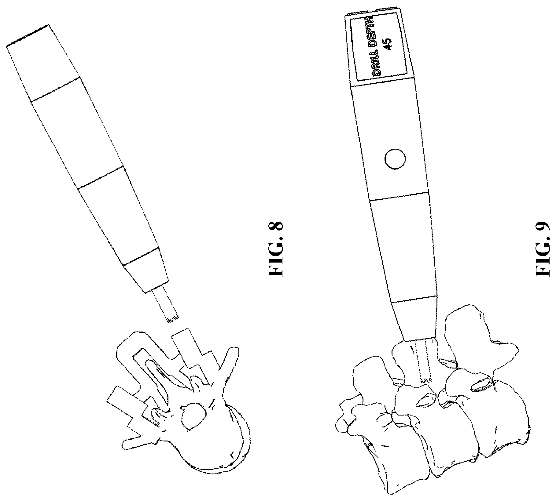
FIG. 8 shows another perspective view of the drilling apparatus of FIG. 7;
FIG. 9 shows a drilling apparatus according to another embodiment wherein the apparatus is aligned with a different vertebral body;
FIG. 10 shows the drilling apparatus according to another embodiment wherein the apparatus is received by a surgical guide;
FIG. 11 shows a rear elevation view of the drilling apparatus shown in FIG. 10;
FIGS. 12-15 show alternate views of the drilling apparatus depicted in FIG. 10;
FIG. 16 shows a drilling apparatus according to another embodiment aligned with a different surgical guide;
FIGS. 17-18 show alternate views of the drilling apparatus depicted in FIG. 16;
FIG. 19 shows a drilling apparatus according to another embodiment aligned with a surgical cutting guide;
FIG. 20 shows the apparatus of FIG. 19 with a cutting tool coupled to the apparatus for use with the surgical cutting guide of FIG. 19;
FIG. 21 is a detailed and partial sectional view of the apparatus of FIG. 20;
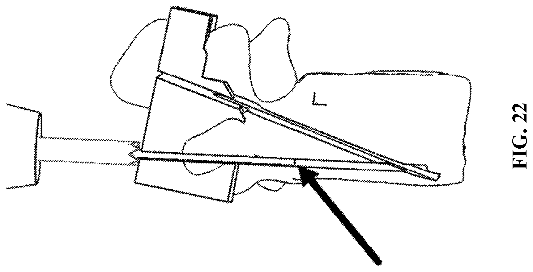
FIG. 22 is another detailed and partial sectional view showing the apparatus of FIG. 20 with the cutting tool inserted through the cutting guide of FIG. 20;
FIG. 23 shows the drilling apparatus according to another embodiment where the apparatus if aligned with a cutting guide comprising one or more sensors;
FIG. 24 shows a perspective view of the apparatus and guide of FIG. 23; and
FIGS. 25-26 show the drilling apparatus and one or more sensors according to an alternate embodiment.
Similar components and/or features may have the same reference number. Components of the same type may be distinguished by a letter following the reference number. If only the reference number is used, the description is applicable to any one of the similar components having the same reference number.
DETAILED DESCRIPTION OF THE INVENTION
The present disclosure has significant benefits across a broad spectrum of endeavors. It is the Applicant's intent that this specification and the claims appended hereto be accorded a breadth in keeping with the scope and spirit of the disclosure and various embodiments disclosed, despite what might appear to be limiting language imposed by specific examples disclosed in the specifications. To acquaint persons skilled in the pertinent arts most closely related to the present disclosure, preferred and/or exemplary embodiments are described in detail without attempting to describe all of the various forms and modifications in which the novel apparatus, devices, systems and methods might be embodied. As such, the embodiments described herein are illustrative, and as will become apparent to those skilled in the arts, may be modified in numerous ways within the spirit of the disclosure.
By way of providing additional background, context, and to further satisfy the written description requirements of 35 U.S.C. .sctn. 112, the following are incorporated by reference in their entireties for the express purpose of explaining and further describing the various tools and other apparatus commonly associated therewith surgical procedures, including minimally invasive surgery ("MIS") procedures: U.S. Pat. No. 6,309,395 to Smith et al.; U.S. Pat. No. 6,142,998 to Smith et al.; U.S. Pat. No. 7,014,640 to Kemppanien et al.; U.S. Pat. No. 7,406,775 to Funk, et al.; U.S. Pat. No. 7,387,643 to Michelson; U.S. Pat. No. 7,341,590 to Ferree; U.S. Pat. No. 7,288,093 to Michelson; U.S. Pat. No. 7,207,992 to Ritland; U.S. Pat. No. 7,077,864 Byrd III, et al.; U.S. Pat. No. 7,025,769 to Ferree; U.S. Pat. No. 6,719,795 to Cornwall, et al.; U.S. Pat. No. 6,364,880 to Michelson; U.S. Pat. No. 6,328,738 to Suddaby; U.S. Pat. No. 6,290,724 to Marino; U.S. Pat. No. 6,113,602 to Sand; U.S. Pat. No. 6,030,401 to Marino; U.S. Pat. No. 5,865,846 to Bryan, et al.; U.S. Pat. No. 5,569,246 to Ojima, et al.; U.S. Pat. No. 5,527,312 to Ray; and U.S. Pat. Appl. No. 2008/0255564 to Michelson.
Several advantages of an improved drill apparatus have previously been described herein, but for convenience, the following advantages are achieved by the drill apparatus contemplated by this disclosure: the drill apparatus may be handheld, and in one embodiment may be battery powered to eliminate the need for cords or cables; the drill apparatus may comprise a drill bit selectively housed in the drill body, which avoids injury to the user and contamination to those who come into contact with the drill bit; The drill apparatus may comprise a modular design allowing for changing out different sized drill bits or reamers; the drill apparatus may comprise a sleeve located proximate to the tip of drill for mating the drill with or guiding the drill bit through, for example, a cannula or surgical guide, as described in greater detail below.
The drill apparatus may additionally comprise or alternatively communicate with at least one sensor or scanner that is configured to read or sense the required depth based on one or more indicia, then drill to the associated depth correlating to the one or more indicia. The drill apparatus may comprise computational machinery to provide a user with the ability to program certain operations, safety features, etc., and which may further comprise the ability to read and/or write to a removable memory card. These and other advantages will be appreciated after reviewing the complete disclosure relating to various embodiments of the drilling apparatus described herein.
Several views of the drill apparatus described herein are shown in FIGS. 1-26. The drilling apparatus preferably comprises at least one user interface, which may display depth, speed, resistance or other measurements (for estimating bone quality). A user may quickly and easily adjust parameters of the drill apparatus via the interface, which may be comprised of a touch screen or other inputs, such as pushbuttons.
An integral display, may be provided, which preferably shows the precise depth of the drill bit and other settings, such as the level the drill is set for. A user may adjust these settings and/or preset levels in case there is a change in the pre-determined drill depth, or if the user decides to abort the current operation and implement a new plan.
The programmable depth of the drilling apparatus is best illustrated in FIGS. 1-4. Referring now to FIG. 1, the drill apparatus is shown with the drill bit in a fully extended position. The display is depicted at the opposite end of the drill bit, but in alternate embodiments may be located centrally on the drill body or at the drill bit end of the drill apparatus. This display may indicate various parameters or other information of importance to the user, such as "Depth" and the "Drill To" quantities discussed elsewhere in this application. In FIG. 2, the drill apparatus of FIG. 1 is shown with the drill bit in a half-extended position. In FIG. 3, the drill bit is fully retracted. Variations on these positions are considered within the scope of the present disclosure. It is expressly understood that these drawings are not to scale, and in certain embodiments the drill bit may extend more or less than shown in the drawing figures.
Referring now to FIG. 4, the drilling apparatus may comprise pre-programmed settings for each level in a human spine or other area of unique patient anatomy. Pre-surgical plans or pre-programmed depths for determining the drill bit extension from the body of the drill may be determined, for example, by using CAD software, 3-dimensional models, or in certain embodiments from CT scans or xrays of a particular patient. The drill apparatus preferably comprises an internal motor, with one or more computational apparatus to establish and control the rotation and direction of the drill bit, the drill bit depth, etc.
The user may initially program or customize the drill depth into the drill using a computer or graphic or other interface, preferably located on the body of the drill. A flash-drive or memory card can also be used, such as a card or drive loaded with information and ultimately accepted by (i.e., downloaded to) the computational machinery housed within the drill. Pre-determined depths may also be read by the drill using markings or indicia located on, for example, a drilling guide, an RFID marker, or a barcode, including such indicia located on a fixation device to be used with the drill apparatus.
The drill bit may extend from the drill body, and may automatically "zero" its depth in relation to the surface to be drilled. The user may then press a button switch or icon on the interface, and advance the drill bit to the pre-determined depth. After the drill bit reaches a pre-determined depth, the drill may be configured to stop and not proceed further, thereby preventing overtravel. The drill may further comprise a setting that achieves an "auto zero" when the drill bit contacts a certain resistance or hardness of material, for example, cortical bone. The drill may further comprise an automatic shut off or emergency stop sequence if secondary material density is contacted by the drill bit, such as in the event the bone face of a patient is pierced. These features may be used to prevent a surgeon from going through the vertebral body in a patient's spine, or other bones where a drilling procedure is required.
In other embodiments, the drill apparatus may be selectively programmed depending on the patient's bone quality, so that the drill may automatically detect how hard the materials are that the drill is to come into contact with (i.e., cortical vs cancellous bone), and therefore what speed, depth, power and acceleration is required to complete the drilling procedure. This information may be gathered from the CT scan or xray of the patient, and may either be programed into the drill (by using the graphic interface, for example) or may be downloaded to use with, by way of example, the drill.
The drill apparatus may also comprise an automatic shut off or "override" for various in/out/in trajectories. To further illustrate, the drill may automatically shut off if certain trajectories (such as those pre-determined by the user and loaded in the computational machinery of the drill) are departed from while the drill apparatus is in use. If the drill feels resistance, for instance the drill may manually or automatically mark the depth so the user may know where certain anatomical features, landmarks or impediments are located. In addition, a display associated with the drill apparatus may provide the drill depth and bone resistance or other critical information as the drill apparatus is in use.
Referring again to FIG. 4, the drill apparatus may accept one or more types of external devices, such as external drivers or memory cards, for downloading information to be accessed and/or used by computational machinery located within the drill body. In other embodiments, information and program may be received by the drill apparatus by the way of wireless or Bluetooth communication protocols, or otherwise without requiring a driver or card. Here, the display indicates that the user is to "Load Mem." or "memory" for programming the drill or achieving other functionality described herein.
Referring now to FIGS. 5-6, the drill apparatus is shown relative to a patient's anatomical structure, as an example of the material to be used in conjunction with the drill apparatus described herein. As shown in these Figures, the drill apparatus may comprise a hard stop to prevent penetration of the drill apparatus into the anatomical feature beyond the extension of the drill bit from the drill body, which is programmable and may be pre-determined before the drill apparatus is to be used. The display may include a dynamic setting that changes as the drill bit extends from the drill body, as shown in FIGS. 5-6. In at least one embodiment, the drill apparatus may automatically dispense gel or foam to minimize bleeding in the patient or otherwise facilitate the drilling procedure. Reservoirs for housing the gel or foam may be either internal or external to the drill body.
The drill apparatus described herein may be used in conjunction with guides such as those commercially known as FIREFLY navigation guides, which are disclosed in part by U.S. Pat. Nos. 8,758,357, 8,870,889, 9,198,678 and 9,642,633. In this scenario, the drill apparatus would be centered over one of the cannula of the FIREFLY guides. The drill may then either be preset to drill the levels in order, or alternatively the drill could read/scan which level it is situated at using one of the indicia identified above (including RFID or "keyed" cannula or other devices bearing the indicia). Once the drill is placed above a guide cannula, the "instrument sleeve" contained within the drill advances into the guide to prevent the drill from contacting the guide. The drill is then advanced, per the procedure described above, and comes to a stop at a pre-determined depth associated with the particular guide or the imported patient data, or both. When used with FIREFLY guides described above, the drill may light up different colors to match the trajectories of the patient specific surgical plan on the display of the drill, such that the current level to be drilled would be displayed on the screen at any given time in the procedure or surgical plan.
Referring now to FIG. 7, the drilling apparatus according to one embodiment may be received within or otherwise used in connection with a surgical guide, such as a FIREFLY navigation guide described above. According to this embodiment, the bit of the drilling apparatus is configured to be received within a hollow sleeve associated with the surgical guide such that the bit may only contact the boney anatomy in a certain location, and in a specific orientation, and in certain embodiments only to a certain depth. Further details are described in U.S. Pat. No. 9,642,633 which is incorporated herein by reference. FIG. 8 shows another perspective view of the embodiment shown in FIG. 7.
FIG. 9 shows a drilling apparatus according to another embodiment wherein the apparatus is aligned with a different vertebral body. In this embodiment, the drilling apparatus may be configured, either through programming or other means described herein, to extend from the chuck of the drill only by a certain amount, thereby providing accurate depth control. The programmed or configured depth may be reflected on the display of the apparatus, as shown in FIG. 9. Thus, even without a surgical guide and hard stops to prevent over-drilling, the drilling apparatus may be used in a manner to prevent drilling operation beyond a certain depth.
FIG. 10 shows the drilling apparatus according to another embodiment wherein the apparatus is received by a surgical guide. According to this embodiment, the chuck of the drill may be received within the hollow sleeve of the surgical guide, providing stability and positional accuracy prior to operating the drill. In this manner, the drilling apparatus may be pre-programmed with a controlled depth, assuming that the chuck of the drill is going to be positioned in the hollow sleeve. Once the drill is in position relative to the guide, the bit may extend from the chuck and into the boney anatomy to the pre-programmed depth. Once completed, the operation may also include a program to retract the bit into the chuck before the drill is removed from the surgical guide.
FIG. 11 shows a rear elevation view of the drilling apparatus shown in FIG. 10. In this embodiment, one or more indicia on the body of the drill may provide signals to the operator and provide instruction on which direction to move the proximal end of the drilling apparatus to achieve the appropriate alignment and orientation. For example, one of the arrows shown in FIG. 11 may illuminate, either temporarily or permanently, to indicate the proximal end of the drilling apparatus needs to move in the direction of the arrow to achieve the desired trajectory of the drill bit. While this embodiment is shown with the surgical guide of FIG. 10, it is expressly understood that these features may be incorporated with any of the embodiments described herein. For further illustration of this embodiment, FIGS. 12-15 are provided and depict alternate views of the drilling apparatus depicted in FIG. 10.
FIG. 16 shows a drilling apparatus according to another embodiment aligned with a different surgical guide. Although pedicle screw guides are the primary guide described in U.S. Pat. No. 9,642,633, the drilling apparatus may be used with a variety of bits, including drilling bits, cutting bits, and other types of blades for the desired operation. In certain embodiments the drill tip serves as an instrument sleeve and is inserted into the hollow sleeve of the guide. The tip can be removable, so that drills or other tools with different diameters may be changed to accommodate different procedures or use with different guide sizes. The sleeve protects the plastic guide from the drill bit to minimize debris left in the patient. The drill tip features a trephined tip for securely sitting on the bone surface. The tip may be removed and a smooth attachment may be inserted for use with a drill guide if the trephined tip is not required. Guides may vary as well based on the surgical procedure to be performed, including PSG, MNG, and osteotomy Guides. In FIG. 16, the guide shown is a MNG guide that has at least one hollow sleeve for receiving the drill bit or the drill chuck, as described above in relation to FIGS. 7 and 10. Different styles of guides, including laminectomy, osteotomy and other cutting guides, are contemplated for use with the drilling apparatus of the present disclosure. FIGS. 17-18 show alternate views of the drilling apparatus depicted in FIG. 16. As with the previous embodiments, the drill apparatus may be pre-programmed to include a controlled depth using the surgical guide to prevent improper use.
FIG. 19 shows a drilling apparatus according to another embodiment aligned with an osteotomy guide. In this embodiment, a cutting blade may be connected to the chuck of the drilling apparatus for cutting a path aligned with the path of the osteotomy guide. The guide may comprise one or multiple paths for guiding the blade of the apparatus. In a preferred embodiment, the guides may only permit the blade but not the chuck to enter the paths of the guide. In an alternate embodiment, the guide may permit both the blade and the chuck to enter the paths of the guide.
FIG. 20 shows the apparatus of FIG. 19 with a cutting tool or blade coupled to the apparatus. Here, the blade is sized to be received within the path of the osteotomy guide, and only to the depth permitted by the guide. The guide has narrow paths so that the blade may not vary from the desired trajectory, or else it will contact the surface of the guide. In certain embodiments, the drilling apparatus may be configured to sense the increased resistance of the blade hitting the wall of the guide and suspend operation of the drilling apparatus. The second path may also receive the blade of the drilling apparatus. FIGS. 21-22 are detailed and partial sectional views of the apparatus of FIG. 20.
In certain embodiments, the drill can function to protect patient anatomy and minimize buildup of heat during operation. For example, as the drill bit extends from the drill body it can sense resistance in the material it is drilling and enter a bump cycle where the drill bit extends and retracts while rotating to safely pierce and minimize heat buildup at the cortical shell of the bone. Once the cortical shell is completely drilled the bit continuously extends to the programmed depth and then retracts into the drill body. The drill then resets and the computer changes to the next programmed depth or the operator can select a new depth.
FIG. 23 shows the drilling apparatus according to another embodiment where the apparatus if aligned with a cutting guide comprising one or more sensors. The drill reads a drill depth based on the sensor reading, where the sensor is embedded in the body of the guide. The sensor may be programmed and then embedded into the guide during manufacturing, or may be a preconfigured sensor to detect the presence of the tip of the drilling apparatus based on proximity to the sensor. During operation, the drill may detect the sensor and is then proceed to operate. The guide may comprise additional sensors to detect if the tip of the apparatus is approaching a dangerous area or at risk of over-penetrating. FIG. 24 shows a perspective view of the apparatus and guide of FIG. 23.
FIGS. 25-26 show the drilling apparatus and one or more sensors according to an alternate embodiment. The drill may be used with sensors placed on the patient's body to determine correct angle/trajectory based on pre-surgical planning. Sensors may be placed on the vertebra/lamina/pedicles or on a piece of plastic or other carrier that fits on the patient's anatomy (in positions determined during pre-surgical planning). The sensors communicate with the drill and locate where it is in 3D space based on pre-surgical planning measurements or from the 3D segmentation of the preoperative CT scan. The computer module in the drill (or a separate computer) may instruct an operator how to orient the drill relative to the patient's anatomy and entry point. Alternatively, the indicia on the drill may illuminate, send audible signals or otherwise inform the user when the drill is out of preferred or required alignment, and may further indicate the direction the drill should be pivoted, rotated or positioned to achieve the desired trajectory of the drill bit.
When the drill is in the correct position, it unlocks and allows the surgeon to drill to the preprogrammed depth. The lock mechanism is an internal feature of the drill that keeps the assembly from moving axially to extend the drill bit. This may be a collar, sliding pin or lock ring that can also be manually overridden by button/switch on the external part of the drill body. To unlock, the drill must be located at the correct entry point location and positioned correctly in the sagittal and transverse planes relative to the vertebral body. By creating patient specific guides or patient matched plastic blocks embedded with sensors, the drill can triangulate its position relative to the adjacent sensors and give feedback to the operator on correct placement and trajectory of the drill. Once the correct entry point position and trajectory are found, the drill unlocks and the drilling feature can be activated.
Sensors can be planned for positions on the same vertebral level in ideal location for a minimally invasive procedure such that it does not dissect past the facet capsules of the vertebra. If the drill gets off the planned trajectory it will automatically stop drilling and retract into the drill body and wait for the surgeon to realign the drill. Once the trajectory is drilled, the sensors are removed and placed on the next level, or they are left on the same level if the anatomy is fused.
The drill can also feature a barcode, radio frequency identification device ("RFID") or quick response ("QR") code reader that reads a code printed on the guide, so that pre-loading of the surgical plan or depth is not required. The code or ID be can read by the reader and relayed to the processor in real time. In a preferred embodiment, the scanner on the drill scans the code on the guide and sets the drill depth on the drill. The drill can then be used to drill that level to the correct depth without having to load data onto the drill or preprogram the depths.
The surgical guides and cutting guides described herein may be manufactured via additive manufacturing. In the context of spinal implants, the surgical guides may be used in all approaches (anterior, direct lateral, transforaminal, posterior, posterior lateral, direct lateral posterior, etc). Specific features of the surgical guides described herein can address certain surgical objectives, for example restoring lordosis, restoring disc height, restoring sagittal or coronal balance, etc.
Methods for using the apparatus are also disclosed, including methods that include a test or setup step where the operator uses the drill apparatus as described above, but also drills an initial hole at a selected trajectory. Next, the operator takes the drill bit and disconnects it from drill. Next, the operator takes a fluoroscopy shot to confirm the trajectory, and then reattaches the drill bit and drills to the programmed depth.
The surgical and cutting guides described herein may then be fabricated by any method. Fabrication methods may comprise the use of a rapid prototyping machine, a 3D printing machine, a stereolithography (STL) machine, selective laser sintering (SLS) machine, or a fused deposition modeling (FDM) machine, direct metal laser sintering (DMLS), electron beam melting (EBM) machine, or other additive manufacturing machine.
According to an alternative embodiment, anatomical data may be obtained from an ultrasonic or nuclear medicine scanning device. In yet another alternative embodiment, the data may be supplemented or merged with data from a bone density scanner to fabricate a device that is designed to remain in the patient after the surgical procedure is completed, or alternatively to achieve further control over the orientation of any desired axes, particularly where the surgical procedure involves insertion of one or more implantable devices.
One having skill in the art will appreciate that embodiments of the present disclosure may have various sizes. The sizes of the various elements of embodiments of the present disclosure may be sized based on various factors including, for example, the anatomy of the patient, the person or other device operating with or otherwise using the apparatus, the surgical site location, physical features of the devices and instruments used with the apparatus described herein, including, for example, width, length and thickness, and the size of the surgical apparatus.
One having skill in the art will appreciate that embodiments of the present disclosure may be constructed of materials known to provide, or predictably manufactured to provide the various aspects of the present disclosure. These materials may include, for example, stainless steel, titanium alloy, aluminum alloy, chromium alloy, and other metals or metal alloys. These materials may also include, for example, PEEK, carbon fiber, ABS plastic, polyurethane, polyethylene, photo-polymers, resins, particularly fiber-encased resinous materials rubber, latex, synthetic rubber, synthetic materials, polymers, and natural materials.
One having skill in the art will appreciate that embodiments of the present disclosure may be used in conjunction devices that employ automated or semi-automated manipulation. Various apparatus and implants described herein may be provided to facilitate or control the entry point, angular trajectory, height, and/or head orientation of a screw, for example. For example, the drill may include further attachments to use with taps, burrs, trials or other surgical tools and instruments.
Additional benefits of the systems and methods described herein include improving device fixation, and/or preventing unwanted contact between devices and patient anatomy (e.g. the patient's spinal cord). The further use of methods described above, including the use of software analytics, may further aid in determining screw placement and orientation to achieve the ideal screw placement and/or rod shape. For example, the use of various apparatus described herein to achieve desired screw placement and orientation in turn provides improved alignment of a secondary device, such as a rod, with the screws heads. This benefit in turn allows the surgeon/user to achieve optimal sagittal and/or coronal alignment, which assists in rod placement and improves correction of the patient's anatomy.
While various embodiments of the present disclosure have been described in detail, it is apparent that modifications and alterations of those embodiments will occur to those skilled in the art. However, it is to be expressly understood that such modifications and alterations are within the scope and spirit of the present disclosure, as set forth in the following claims. For further illustration, the information and materials supplied with the provisional and non-provisional patent applications from which this application claims priority are expressly made a part of this disclosure and incorporated by reference herein in their entirety.
It is expressly understood that where the term "patient" has been used to describe the various embodiments of the disclosure, the term should not be construed as limiting in any way. For instance, a patient could be either a human patient or an animal patient, and the apparatus and methods described herein apply equally to veterinary science as they would to surgical procedures performed on human anatomy. The apparatus and methods described herein therefore have application beyond surgical procedures used by spinal surgeons, and the concepts may be applied to other types of "patients" and procedures without departing from the spirit of the present disclosure.
The foregoing discussion of the disclosure has been presented for purposes of illustration and description. The foregoing is not intended to limit the disclosure to the form or forms disclosed herein. In the foregoing Detailed Description for example, various features of the disclosure are grouped together in one or more embodiments for the purpose of streamlining the disclosure. This method of disclosure is not to be interpreted as reflecting an intention that the claimed disclosure requires more features than are expressly recited in each claim. Rather, as the following claims reflect, inventive aspects lie in less than all features of a single foregoing disclosed embodiment. Thus, the following claims are hereby incorporated into this Detailed Description, with each claim standing on its own as a separate preferred embodiment of the disclosure.
The present inventions, in various embodiments, include components, methods, processes, systems and/or apparatuses substantially as depicted and described herein, including various embodiments, subcombinations, and subsets thereof. Those of skill in the art will understand how to make and use the present inventions after understanding the present disclosure. The present inventions, in various embodiments, include providing devices and processes in the absence of items not depicted and/or described herein or in various embodiments hereof, including in the absence of such items as may have been used in previous devices or processes, e.g., for improving performance, achieving ease and\or reducing cost of implementation.
Moreover, though the present disclosure has included description of one or more embodiments and certain variations and modifications, other variations and modifications are within the scope of the disclosure, e.g., as may be within the skill and knowledge of those in the art, after understanding the present disclosure. It is intended to obtain rights which include alternative embodiments to the extent permitted, including alternate, interchangeable and/or equivalent structures, functions, ranges or steps to those claimed, whether or not such alternate, interchangeable and/or equivalent structures, functions, ranges or steps are disclosed herein, and without intending to publicly dedicate any patentable subject matter.
* * * * *
References
D00000
D00001
D00002
D00003
D00004
D00005
D00006
D00007
D00008
D00009
D00010
D00011
D00012

D00013

D00014
D00015

D00016

D00017

XML
uspto.report is an independent third-party trademark research tool that is not affiliated, endorsed, or sponsored by the United States Patent and Trademark Office (USPTO) or any other governmental organization. The information provided by uspto.report is based on publicly available data at the time of writing and is intended for informational purposes only.
While we strive to provide accurate and up-to-date information, we do not guarantee the accuracy, completeness, reliability, or suitability of the information displayed on this site. The use of this site is at your own risk. Any reliance you place on such information is therefore strictly at your own risk.
All official trademark data, including owner information, should be verified by visiting the official USPTO website at www.uspto.gov. This site is not intended to replace professional legal advice and should not be used as a substitute for consulting with a legal professional who is knowledgeable about trademark law.