Loading unit locking collar with rotational actuated release
Sgroi A
U.S. patent number 10,743,880 [Application Number 15/974,029] was granted by the patent office on 2020-08-18 for loading unit locking collar with rotational actuated release. This patent grant is currently assigned to Covidien LP. The grantee listed for this patent is Covidien LP. Invention is credited to Anthony Sgroi.


View All Diagrams
| United States Patent | 10,743,880 |
| Sgroi | August 18, 2020 |
Loading unit locking collar with rotational actuated release
Abstract
A loading unit includes a shell assembly and a locking collar. The shell assembly has an annular ring that defines a locking slot and a proximal opening. The proximal opening configured to receive a distal end portion of the surgical instrument. The locking collar is rotatably disposed about the annular ring. The locking collar has a body including a flexible tab that has an inwardly extending lock. The locking collar is moveable about the annular ring between a locked and unlocked configuration. In the locked configuration, the lock passes through the locking slot and into the proximal opening of the annular ring. In the unlocked configuration, the body of the locking collar is rotated about the annular ring from the locked configuration to move the lock from within the proximal opening.
| Inventors: | Sgroi; Anthony (Wallingford, CT) | ||||||||||
|---|---|---|---|---|---|---|---|---|---|---|---|
| Applicant: |
|
||||||||||
| Assignee: | Covidien LP (Mansfield,
MA) |
||||||||||
| Family ID: | 56958844 | ||||||||||
| Appl. No.: | 15/974,029 | ||||||||||
| Filed: | May 8, 2018 |
Prior Publication Data
| Document Identifier | Publication Date | |
|---|---|---|
| US 20180256168 A1 | Sep 13, 2018 | |
Related U.S. Patent Documents
| Application Number | Filing Date | Patent Number | Issue Date | ||
|---|---|---|---|---|---|
| 14859590 | Sep 21, 2015 | 9980730 | |||
| Current U.S. Class: | 1/1 |
| Current CPC Class: | A61B 17/068 (20130101); A61B 17/105 (20130101); A61B 17/1155 (20130101); A61B 2017/00477 (20130101); A61B 2017/00473 (20130101); A61B 17/162 (20130101); A61B 2017/00526 (20130101) |
| Current International Class: | A61B 17/115 (20060101); A61B 17/068 (20060101); A61B 17/10 (20060101); A61B 17/16 (20060101); A61B 17/00 (20060101) |
| Field of Search: | ;227/175.1-182.1 ;606/139,153-154,219 |
References Cited [Referenced By]
U.S. Patent Documents
| 1296042 | March 1919 | Bralove |
| 2110397 | March 1938 | Kangas |
| 3193165 | July 1965 | Akhalaya et al. |
| 3388847 | June 1968 | Kasulin et al. |
| 3552626 | January 1971 | Astafiev et al. |
| 3638652 | February 1972 | Kelley |
| 3656494 | April 1972 | Cornett |
| 3771526 | November 1973 | Rudie |
| 3980805 | September 1976 | Lipari |
| 4183691 | January 1980 | Van Melle |
| 4198982 | April 1980 | Fortner et al. |
| 4207898 | June 1980 | Becht |
| 4289133 | September 1981 | Rothfuss |
| 4304236 | December 1981 | Conta et al. |
| 4319576 | March 1982 | Rothfuss |
| 4350160 | September 1982 | Kolesov et al. |
| 4351466 | September 1982 | Noiles |
| 4379457 | April 1983 | Gravener et al. |
| 4473077 | September 1984 | Noiles et al. |
| 4476863 | October 1984 | Kanshin et al. |
| 4485817 | December 1984 | Swiggett |
| 4488523 | December 1984 | Shichman |
| 4505272 | March 1985 | Utyamyshev et al. |
| 4505414 | March 1985 | Filipi |
| 4520817 | June 1985 | Green |
| 4550870 | November 1985 | Krumme et al. |
| 4573468 | March 1986 | Conta et al. |
| 4576167 | March 1986 | Noiles |
| 4592354 | June 1986 | Rothfuss |
| 4603693 | August 1986 | Conta et al. |
| 4606343 | August 1986 | Conta et al. |
| 4632290 | December 1986 | Green et al. |
| 4646745 | March 1987 | Noiles |
| 4647241 | March 1987 | Weber |
| 4665917 | May 1987 | Clanton et al. |
| 4667673 | May 1987 | Li |
| 4671445 | June 1987 | Barker et al. |
| 4700703 | October 1987 | Resnick et al. |
| 4703887 | November 1987 | Clanton et al. |
| 4708141 | November 1987 | Inoue et al. |
| 4717063 | January 1988 | Ebihara |
| 4752024 | June 1988 | Green et al. |
| 4754909 | July 1988 | Barker et al. |
| 4776506 | October 1988 | Green |
| 4817847 | April 1989 | Redtenbacher et al. |
| 4869534 | September 1989 | Ketcham |
| 4873977 | October 1989 | Avant et al. |
| 4893662 | January 1990 | Gervasi |
| 4903697 | February 1990 | Resnick et al. |
| 4907591 | March 1990 | Vasconcellos et al. |
| 4917114 | April 1990 | Green et al. |
| 4957499 | September 1990 | Lipatov et al. |
| 4962877 | October 1990 | Hervas |
| 5005749 | April 1991 | Aranyi |
| 5042707 | August 1991 | Taheri |
| 5047039 | September 1991 | Avant et al. |
| 5104025 | April 1992 | Main et al. |
| 5119983 | June 1992 | Green et al. |
| 5122156 | June 1992 | Granger et al. |
| 5139513 | August 1992 | Segato |
| 5158222 | October 1992 | Green et al. |
| 5188638 | February 1993 | Tzakis |
| 5193731 | March 1993 | Aranyi |
| 5197648 | March 1993 | Gingold |
| 5197649 | March 1993 | Bessler et al. |
| 5205459 | April 1993 | Brinkerhoff et al. |
| 5221036 | June 1993 | Takase |
| 5222963 | June 1993 | Brinkerhoff et al. |
| 5253793 | October 1993 | Green et al. |
| 5261920 | November 1993 | Main et al. |
| 5271543 | December 1993 | Grant et al. |
| 5271544 | December 1993 | Fox et al. |
| 5275322 | January 1994 | Brinkerhoff et al. |
| 5275443 | January 1994 | Klinger |
| 5282810 | February 1994 | Allen et al. |
| 5285944 | February 1994 | Green et al. |
| 5285945 | February 1994 | Brinkerhoff et al. |
| 5291910 | March 1994 | Bui |
| 5292053 | March 1994 | Bilotti et al. |
| 5309927 | May 1994 | Welch |
| 5312024 | May 1994 | Grant et al. |
| 5314435 | May 1994 | Green et al. |
| 5314436 | May 1994 | Wilk |
| 5330486 | July 1994 | Wilk |
| 5333773 | August 1994 | Main et al. |
| 5344059 | September 1994 | Green et al. |
| 5346115 | September 1994 | Perouse et al. |
| 5348259 | September 1994 | Blanco et al. |
| 5350104 | September 1994 | Main et al. |
| 5355897 | October 1994 | Pietrafitta et al. |
| 5360154 | November 1994 | Green |
| 5368215 | November 1994 | Green et al. |
| 5392979 | February 1995 | Green et al. |
| 5395030 | March 1995 | Kuramoto et al. |
| 5403333 | April 1995 | Kaster et al. |
| 5404870 | April 1995 | Brinkerhoff et al. |
| 5411508 | May 1995 | Bessler et al. |
| 5425738 | June 1995 | Gustafson et al. |
| 5433721 | July 1995 | Hooven et al. |
| 5437684 | August 1995 | Calabrese et al. |
| 5439156 | August 1995 | Grant et al. |
| 5443198 | August 1995 | Viola et al. |
| 5447514 | September 1995 | Gerry et al. |
| 5454825 | October 1995 | Van Leeuwen et al. |
| 5464415 | November 1995 | Chen |
| 5470006 | November 1995 | Rodak |
| 5474223 | December 1995 | Viola et al. |
| 5481949 | January 1996 | Yen |
| 5497934 | March 1996 | Brady et al. |
| 5498042 | March 1996 | Dole |
| 5503635 | April 1996 | Sauer et al. |
| 5522534 | June 1996 | Viola et al. |
| 5533661 | July 1996 | Main et al. |
| 5560257 | October 1996 | DeBisschop |
| 5588579 | December 1996 | Schnut et al. |
| 5609285 | March 1997 | Grant et al. |
| 5626591 | May 1997 | Kockerling et al. |
| 5632433 | May 1997 | Grant et al. |
| 5639008 | June 1997 | Gallagher et al. |
| 5641111 | June 1997 | Ahrens et al. |
| 5658300 | August 1997 | Bito et al. |
| 5669918 | September 1997 | Balazs et al. |
| 5685474 | November 1997 | Seeber |
| 5709335 | January 1998 | Heck |
| 5715987 | February 1998 | Kelley et al. |
| 5718360 | February 1998 | Green et al. |
| 5720755 | February 1998 | Dakov |
| 5727897 | March 1998 | Liu |
| 5732872 | March 1998 | Bolduc et al. |
| 5749896 | May 1998 | Cook |
| 5758814 | June 1998 | Gallagher et al. |
| 5799857 | September 1998 | Robertson et al. |
| 5814055 | September 1998 | Knodel et al. |
| 5833698 | November 1998 | Hinchliffe et al. |
| 5836503 | November 1998 | Ehrenfels et al. |
| 5839639 | November 1998 | Sauer et al. |
| 5855312 | January 1999 | Toledano |
| 5860581 | January 1999 | Robertson et al. |
| 5868760 | February 1999 | McGuckin, Jr. |
| 5881943 | March 1999 | Heck et al. |
| 5915616 | June 1999 | Viola et al. |
| 5947363 | September 1999 | Bolduc et al. |
| 5951576 | September 1999 | Wakabayashi |
| 5954448 | September 1999 | Shim |
| 5957363 | September 1999 | Heck |
| 5993468 | November 1999 | Rygaard |
| 6024748 | February 2000 | Manzo et al. |
| 6030136 | February 2000 | Bennett |
| 6050472 | April 2000 | Shibata |
| 6053390 | April 2000 | Green et al. |
| D425784 | May 2000 | Beugelsdyk |
| 6068636 | May 2000 | Chen |
| 6083241 | July 2000 | Longo et al. |
| 6102271 | August 2000 | Longo et al. |
| 6117148 | September 2000 | Ravo et al. |
| 6119913 | September 2000 | Adams et al. |
| 6126058 | October 2000 | Adams et al. |
| 6142933 | November 2000 | Longo et al. |
| 6149667 | November 2000 | Hovland et al. |
| 6155610 | December 2000 | Godeau et al. |
| 6176413 | January 2001 | Heck et al. |
| 6179195 | January 2001 | Adams et al. |
| 6193129 | February 2001 | Bittner et al. |
| 6203553 | March 2001 | Robertson et al. |
| 6209773 | April 2001 | Bolduc et al. |
| 6241140 | June 2001 | Adams et al. |
| 6253984 | July 2001 | Heck et al. |
| 6254305 | July 2001 | Taylor |
| 6258107 | July 2001 | Balazs et al. |
| 6264086 | July 2001 | McGuckin, Jr. |
| 6269997 | August 2001 | Balazs et al. |
| 6273897 | August 2001 | Dalessandro et al. |
| 6279809 | August 2001 | Nicolo |
| 6302311 | October 2001 | Adams et al. |
| 6338737 | January 2002 | Toledano |
| 6343731 | February 2002 | Adams et al. |
| 6387105 | May 2002 | Gifford, III et al. |
| 6398795 | June 2002 | McAlister et al. |
| 6402008 | June 2002 | Lucas |
| 6439446 | August 2002 | Perry et al. |
| 6443973 | September 2002 | Whitman |
| 6450390 | September 2002 | Heck et al. |
| 6478210 | November 2002 | Adams et al. |
| 6488197 | December 2002 | Whitman |
| 6491201 | December 2002 | Whitman |
| 6494877 | December 2002 | Odell et al. |
| 6503259 | January 2003 | Huxel et al. |
| 6517566 | February 2003 | Hovland et al. |
| 6520398 | February 2003 | Nicolo |
| 6533157 | March 2003 | Whitman |
| 6551334 | April 2003 | Blatter et al. |
| 6578751 | June 2003 | Hartwick |
| 6585144 | July 2003 | Adams et al. |
| 6588643 | July 2003 | Bolduc et al. |
| 6592596 | July 2003 | Geitz |
| 6601749 | August 2003 | Sullivan et al. |
| 6605078 | August 2003 | Adams |
| 6605098 | August 2003 | Nobis et al. |
| 6612622 | September 2003 | Andre |
| 6626921 | September 2003 | Blatter et al. |
| 6629630 | October 2003 | Adams |
| 6631837 | October 2003 | Heck |
| 6632227 | October 2003 | Adams |
| 6632237 | October 2003 | Ben-David et al. |
| 6652542 | November 2003 | Blatter et al. |
| 6659327 | December 2003 | Heck et al. |
| 6676671 | January 2004 | Robertson et al. |
| 6681979 | January 2004 | Whitman |
| 6685079 | February 2004 | Sharma et al. |
| 6695198 | February 2004 | Adams et al. |
| 6695199 | February 2004 | Whitman |
| 6698643 | March 2004 | Whitman |
| 6716222 | April 2004 | McAlister et al. |
| 6716233 | April 2004 | Whitman |
| 6726697 | April 2004 | Nicholas et al. |
| 6742692 | June 2004 | Hartwick |
| 6743244 | June 2004 | Blatter et al. |
| 6763993 | July 2004 | Bolduc et al. |
| 6769590 | August 2004 | Vresh et al. |
| 6769594 | August 2004 | Orban, III |
| 6820791 | November 2004 | Adams |
| 6821282 | November 2004 | Perry et al. |
| 6827246 | December 2004 | Sullivan et al. |
| 6840423 | January 2005 | Adams et al. |
| 6843403 | January 2005 | Whitman |
| 6846308 | January 2005 | Whitman et al. |
| 6852122 | February 2005 | Rush |
| 6866178 | March 2005 | Adams et al. |
| 6872214 | March 2005 | Sonnenschein et al. |
| 6874669 | April 2005 | Adams et al. |
| 6884250 | April 2005 | Monassevitch et al. |
| 6905504 | June 2005 | Vargas |
| 6938814 | September 2005 | Sharma et al. |
| 6942675 | September 2005 | Vargas |
| 6945444 | September 2005 | Gresham et al. |
| 6953138 | October 2005 | Dworak et al. |
| 6957758 | October 2005 | Aranyi |
| 6959851 | November 2005 | Heinrich |
| 6978922 | December 2005 | Bilotti et al. |
| 6981941 | January 2006 | Whitman et al. |
| 6981979 | January 2006 | Nicolo |
| 7032798 | April 2006 | Whitman et al. |
| 7059331 | June 2006 | Adams et al. |
| 7059510 | June 2006 | Orban, III |
| 7077856 | July 2006 | Whitman |
| 7080769 | July 2006 | Vresh et al. |
| 7086267 | August 2006 | Dworak et al. |
| 7114642 | October 2006 | Whitman |
| 7118528 | October 2006 | Piskun |
| 7122044 | October 2006 | Bolduc et al. |
| 7128748 | October 2006 | Mooradian et al. |
| 7141055 | November 2006 | Abrams et al. |
| 7168604 | January 2007 | Milliman et al. |
| 7179267 | February 2007 | Nolan et al. |
| 7182239 | February 2007 | Myers |
| 7195142 | March 2007 | Orban, III |
| 7207168 | April 2007 | Doepker et al. |
| 7220237 | May 2007 | Gannoe et al. |
| 7234624 | June 2007 | Gresham et al. |
| 7235089 | June 2007 | McGuckin, Jr. |
| RE39841 | September 2007 | Bilotti et al. |
| 7285125 | October 2007 | Viola |
| 7303106 | December 2007 | Milliman et al. |
| 7303107 | December 2007 | Milliman et al. |
| 7309341 | December 2007 | Ortiz et al. |
| 7322994 | January 2008 | Nicholas et al. |
| 7325713 | February 2008 | Aranyi |
| 7334718 | February 2008 | McAlister et al. |
| 7335212 | February 2008 | Edoga et al. |
| 7364060 | April 2008 | Milliman |
| 7398908 | July 2008 | Holsten et al. |
| 7399305 | July 2008 | Csiky et al. |
| 7401721 | July 2008 | Holsten et al. |
| 7401722 | July 2008 | Hur |
| 7407075 | August 2008 | Holsten et al. |
| 7410086 | August 2008 | Ortiz et al. |
| 7413366 | August 2008 | Bensussan |
| 7422137 | September 2008 | Manzo |
| 7422138 | September 2008 | Bilotti et al. |
| 7431191 | October 2008 | Milliman |
| 7438718 | October 2008 | Milliman et al. |
| 7455676 | November 2008 | Holsten et al. |
| 7455682 | November 2008 | Viola |
| 7481347 | January 2009 | Roy |
| 7494038 | February 2009 | Milliman |
| 7506791 | March 2009 | Omaits et al. |
| 7516877 | April 2009 | Aranyi |
| 7527185 | May 2009 | Harari et al. |
| 7537602 | May 2009 | Whitman |
| 7546939 | June 2009 | Adams et al. |
| 7546940 | June 2009 | Milliman et al. |
| 7547312 | June 2009 | Bauman et al. |
| 7556186 | July 2009 | Milliman |
| 7559451 | July 2009 | Sharma et al. |
| 7562442 | July 2009 | Montena |
| 7585306 | September 2009 | Abbott et al. |
| 7588174 | September 2009 | Holsten et al. |
| 7600663 | October 2009 | Green |
| 7611038 | November 2009 | Racenet et al. |
| 7635385 | December 2009 | Milliman et al. |
| 7669747 | March 2010 | Weisenburgh, II et al. |
| 7686201 | March 2010 | Csiky |
| 7694864 | April 2010 | Okada et al. |
| 7699204 | April 2010 | Viola |
| 7708181 | May 2010 | Cole et al. |
| 7717313 | May 2010 | Criscuolo et al. |
| 7721932 | May 2010 | Cole et al. |
| 7726539 | June 2010 | Holsten et al. |
| 7743958 | June 2010 | Orban, III |
| 7744627 | June 2010 | Orban, III et al. |
| 7748645 | July 2010 | Breese |
| 7770776 | August 2010 | Chen et al. |
| 7771440 | August 2010 | Ortiz et al. |
| 7774889 | August 2010 | Weaver |
| 7776060 | August 2010 | Mooradian et al. |
| 7793813 | September 2010 | Bettuchi |
| 7802712 | September 2010 | Milliman et al. |
| 7823592 | November 2010 | Bettuchi et al. |
| 7837079 | November 2010 | Holsten et al. |
| 7837080 | November 2010 | Schwemberger |
| 7837081 | November 2010 | Holsten et al. |
| 7845536 | December 2010 | Viola et al. |
| 7845538 | December 2010 | Whitman |
| 7857187 | December 2010 | Milliman |
| 7886951 | February 2011 | Hessler |
| 7891343 | February 2011 | Braun |
| 7896215 | March 2011 | Adams et al. |
| 7900806 | March 2011 | Chen et al. |
| 7909039 | March 2011 | Hur |
| 7909219 | March 2011 | Cole et al. |
| 7909222 | March 2011 | Cole et al. |
| 7909223 | March 2011 | Cole et al. |
| 7913892 | March 2011 | Cole et al. |
| 7918377 | April 2011 | Measamer et al. |
| 7922062 | April 2011 | Cole et al. |
| 7922743 | April 2011 | Heinrich et al. |
| 7931183 | April 2011 | Orban, III |
| 7938307 | May 2011 | Bettuchi |
| 7942302 | May 2011 | Roby et al. |
| 7951166 | May 2011 | Orban, III et al. |
| 7959050 | June 2011 | Smith et al. |
| 7967181 | June 2011 | Viola et al. |
| 7975895 | July 2011 | Milliman |
| 8002795 | August 2011 | Beetel |
| 8006701 | August 2011 | Bilotti et al. |
| 8006889 | August 2011 | Adams et al. |
| 8011551 | September 2011 | Marczyk et al. |
| 8011554 | September 2011 | Milliman |
| 8016177 | September 2011 | Bettuchi et al. |
| 8016858 | September 2011 | Whitman |
| 8020741 | September 2011 | Cole et al. |
| 8025199 | September 2011 | Whitman et al. |
| 8028885 | October 2011 | Smith et al. |
| 8029024 | October 2011 | Guest |
| 8038046 | October 2011 | Smith et al. |
| 8043207 | October 2011 | Adams |
| 8066167 | November 2011 | Measamer et al. |
| 8066169 | November 2011 | Viola |
| 8070035 | December 2011 | Holsten et al. |
| 8070037 | December 2011 | Csiky |
| 8096458 | January 2012 | Hessler |
| 8109426 | February 2012 | Milliman et al. |
| 8109427 | February 2012 | Orban, III |
| 8113406 | February 2012 | Holsten et al. |
| 8113407 | February 2012 | Holsten et al. |
| 8123103 | February 2012 | Milliman |
| 8128645 | March 2012 | Sonnenschein et al. |
| 8132703 | March 2012 | Milliman et al. |
| 8136712 | March 2012 | Zingman |
| 8146790 | April 2012 | Milliman |
| 8146791 | April 2012 | Bettuchi et al. |
| 8181838 | May 2012 | Milliman et al. |
| 8192460 | June 2012 | Orban, III et al. |
| 8201720 | June 2012 | Hessler |
| 8203782 | June 2012 | Brueck et al. |
| 8211130 | July 2012 | Viola |
| 8225799 | July 2012 | Bettuchi |
| 8225981 | July 2012 | Criscuolo et al. |
| 8231041 | July 2012 | Marczyk et al. |
| 8231042 | July 2012 | Hessler et al. |
| 8257391 | September 2012 | Orban, III et al. |
| 8267301 | September 2012 | Milliman et al. |
| 8272552 | September 2012 | Holsten et al. |
| 8276802 | October 2012 | Kostrzewski |
| 8281975 | October 2012 | Criscuolo et al. |
| 8286845 | October 2012 | Perry et al. |
| 8308045 | November 2012 | Bettuchi et al. |
| 8312885 | November 2012 | Bettuchi et al. |
| 8313014 | November 2012 | Bettuchi |
| 8317073 | November 2012 | Milliman et al. |
| 8317074 | November 2012 | Ortiz et al. |
| 8322590 | December 2012 | Patel et al. |
| 8328060 | December 2012 | Jankowski et al. |
| 8328062 | December 2012 | Viola |
| 8328063 | December 2012 | Milliman et al. |
| 8328224 | December 2012 | Alsaid |
| 8343185 | January 2013 | Milliman et al. |
| 8353438 | January 2013 | Baxter, III et al. |
| 8353439 | January 2013 | Baxter, III et al. |
| 8353930 | January 2013 | Heinrich et al. |
| 8360295 | January 2013 | Milliman et al. |
| 8365974 | February 2013 | Milliman |
| 8397972 | March 2013 | Kostrzewski |
| 8403942 | March 2013 | Milliman et al. |
| 8408441 | April 2013 | Wenchell et al. |
| 8413870 | April 2013 | Pastorelli et al. |
| 8413872 | April 2013 | Patel |
| 8418905 | April 2013 | Milliman |
| 8418909 | April 2013 | Kostrzewski |
| 8424535 | April 2013 | Hessler et al. |
| 8424741 | April 2013 | McGuckin, Jr. et al. |
| 8430291 | April 2013 | Heinrich et al. |
| 8430292 | April 2013 | Patel et al. |
| 8453910 | June 2013 | Bettuchi et al. |
| 8453911 | June 2013 | Milliman et al. |
| 8485414 | July 2013 | Criscuolo et al. |
| 8490853 | July 2013 | Criscuolo et al. |
| 8511533 | August 2013 | Viola et al. |
| 8551138 | October 2013 | Orban, III et al. |
| 8567655 | October 2013 | Nalagatla et al. |
| 8579178 | November 2013 | Holsten et al. |
| 8590763 | November 2013 | Milliman |
| 8590764 | November 2013 | Hartwick et al. |
| 8590846 | November 2013 | Guthke |
| 8608047 | December 2013 | Holsten et al. |
| 8616428 | December 2013 | Milliman et al. |
| 8616429 | December 2013 | Viola |
| 8622275 | January 2014 | Baxter, III et al. |
| 8631993 | January 2014 | Kostrzewski |
| 8636187 | January 2014 | Hueil et al. |
| 8640940 | February 2014 | Ohdaira |
| 8662370 | March 2014 | Takei |
| 8663258 | March 2014 | Bettuchi et al. |
| 8672931 | March 2014 | Goldboss et al. |
| 8678264 | March 2014 | Racenet et al. |
| 8684248 | April 2014 | Milliman |
| 8684250 | April 2014 | Bettuchi et al. |
| 8684251 | April 2014 | Rebuffat et al. |
| 8684252 | April 2014 | Patel et al. |
| 8733611 | May 2014 | Milliman |
| 8875972 | November 2014 | Weisenburgh, II |
| 8932362 | January 2015 | Katrana |
| 9113885 | August 2015 | Hodgkinson |
| 9402604 | August 2016 | Williams |
| 9506592 | November 2016 | Turnau, III |
| 9974540 | May 2018 | Richard |
| 9980730 | May 2018 | Sgroi |
| 10022126 | July 2018 | Sgroi, Jr. |
| 10117656 | November 2018 | Sgroi, Jr. |
| 10278886 | May 2019 | Fong |
| 2003/0111507 | June 2003 | Nunez |
| 2004/0059227 | March 2004 | Nita et al. |
| 2004/0194324 | October 2004 | Youn-Chyuan |
| 2005/0051597 | March 2005 | Toledano |
| 2005/0107813 | May 2005 | Gilete Garcia |
| 2005/0123344 | June 2005 | Bensussan |
| 2006/0000869 | January 2006 | Fontayne |
| 2006/0011698 | January 2006 | Okada et al. |
| 2006/0097025 | May 2006 | Milliman |
| 2006/0101600 | May 2006 | Weaver |
| 2006/0201989 | September 2006 | Ojeda |
| 2007/0027473 | February 2007 | Vresh et al. |
| 2007/0029363 | February 2007 | Popov |
| 2007/0060952 | March 2007 | Roby et al. |
| 2008/0179375 | July 2008 | Scirica |
| 2008/0308605 | December 2008 | Scirica |
| 2009/0236392 | September 2009 | Cole et al. |
| 2009/0236398 | September 2009 | Cole et al. |
| 2009/0236401 | September 2009 | Cole et al. |
| 2009/0326540 | December 2009 | Estes |
| 2010/0005931 | January 2010 | Lai |
| 2010/0019016 | January 2010 | Edoga et al. |
| 2010/0051668 | March 2010 | Milliman et al. |
| 2010/0084453 | April 2010 | Hu |
| 2010/0147923 | June 2010 | D'Agostino et al. |
| 2010/0163598 | July 2010 | Belzer |
| 2010/0224668 | September 2010 | Fontayne et al. |
| 2010/0230465 | September 2010 | Smith et al. |
| 2010/0258611 | October 2010 | Smith et al. |
| 2010/0264195 | October 2010 | Bettuchi |
| 2010/0327041 | December 2010 | Milliman et al. |
| 2011/0011916 | January 2011 | Levine |
| 2011/0101066 | May 2011 | Farascioni |
| 2011/0114697 | May 2011 | Baxter, III et al. |
| 2011/0114700 | May 2011 | Baxter, III et al. |
| 2011/0132964 | June 2011 | Weisenburgh, II |
| 2011/0142529 | June 2011 | Oh |
| 2011/0144640 | June 2011 | Heinrich et al. |
| 2011/0147432 | June 2011 | Heinrich et al. |
| 2011/0186614 | August 2011 | Kasvikis |
| 2011/0192882 | August 2011 | Hess et al. |
| 2011/0205072 | August 2011 | Ben-Mansour |
| 2011/0276036 | November 2011 | Spranger et al. |
| 2012/0061448 | March 2012 | Zingman |
| 2012/0083826 | April 2012 | Chao |
| 2012/0116363 | May 2012 | Houser |
| 2012/0145755 | June 2012 | Kahn |
| 2012/0193395 | August 2012 | Pastorelli et al. |
| 2012/0193398 | August 2012 | Williams et al. |
| 2012/0232339 | September 2012 | Csiky |
| 2012/0234894 | September 2012 | Kostrzewski |
| 2012/0234896 | September 2012 | Ellerhorst |
| 2012/0273548 | November 2012 | Ma et al. |
| 2012/0273550 | November 2012 | Scirica |
| 2012/0325888 | December 2012 | Qiao et al. |
| 2013/0015232 | January 2013 | Smith et al. |
| 2013/0020372 | January 2013 | Jankowski et al. |
| 2013/0020373 | January 2013 | Smith et al. |
| 2013/0032628 | February 2013 | Li et al. |
| 2013/0056516 | March 2013 | Viola |
| 2013/0060258 | March 2013 | Giacomantonio |
| 2013/0096591 | April 2013 | Hart et al. |
| 2013/0105544 | May 2013 | Mozdzierz et al. |
| 2013/0105546 | May 2013 | Milliman et al. |
| 2013/0105551 | May 2013 | Zingman |
| 2013/0123705 | May 2013 | Holm et al. |
| 2013/0126580 | May 2013 | Smith et al. |
| 2013/0153630 | June 2013 | Miller et al. |
| 2013/0153631 | June 2013 | Vasudevan et al. |
| 2013/0153633 | June 2013 | Casasanta, Jr. et al. |
| 2013/0153634 | June 2013 | Carter |
| 2013/0153638 | June 2013 | Carter et al. |
| 2013/0153639 | June 2013 | Hodgkinson |
| 2013/0175315 | July 2013 | Milliman |
| 2013/0175318 | July 2013 | Felder et al. |
| 2013/0175319 | July 2013 | Felder et al. |
| 2013/0175320 | July 2013 | Mandakolathur Vasudevan et al. |
| 2013/0181029 | July 2013 | Milliman |
| 2013/0181035 | July 2013 | Milliman |
| 2013/0181036 | July 2013 | Olson et al. |
| 2013/0186930 | July 2013 | Wenchell et al. |
| 2013/0193185 | August 2013 | Patel |
| 2013/0193187 | August 2013 | Milliman |
| 2013/0193190 | August 2013 | Carter et al. |
| 2013/0193191 | August 2013 | Stevenson et al. |
| 2013/0193192 | August 2013 | Casasanta, Jr. et al. |
| 2013/0200131 | August 2013 | Racenet |
| 2013/0206816 | August 2013 | Penna |
| 2013/0214027 | August 2013 | Hessler et al. |
| 2013/0214028 | August 2013 | Patel et al. |
| 2013/0228609 | September 2013 | Kostrzewski |
| 2013/0240597 | September 2013 | Milliman et al. |
| 2013/0240600 | September 2013 | Bettuchi |
| 2013/0248581 | September 2013 | Smith et al. |
| 2013/0277411 | October 2013 | Hodgkinson et al. |
| 2013/0277412 | October 2013 | Gresham et al. |
| 2013/0284792 | October 2013 | Ma |
| 2013/0292449 | November 2013 | Bettuchi et al. |
| 2013/0299553 | November 2013 | Mozdzierz |
| 2013/0299554 | November 2013 | Mozdzierz |
| 2013/0306701 | November 2013 | Olson |
| 2013/0306707 | November 2013 | Viola et al. |
| 2014/0008413 | January 2014 | Williams |
| 2014/0012317 | January 2014 | Orban et al. |
| 2014/0309677 | October 2014 | Baldwin |
| 2014/0312095 | October 2014 | Scirica |
| 2015/0108201 | April 2015 | Williams |
| 2015/0320420 | November 2015 | Penna |
| 2015/0351769 | December 2015 | Lee |
| 2015/0374371 | December 2015 | Richard |
| 2016/0000428 | January 2016 | Scirica |
| 2016/0157856 | June 2016 | Williams |
| 2016/0175026 | June 2016 | Bhagat |
| 2016/0192938 | July 2016 | Sgroi, Jr. |
| 2016/0192939 | July 2016 | Sgroi, Jr. |
| 2017/0020526 | January 2017 | Scirica |
| 2017/0079660 | March 2017 | Sgroi |
| 908529 | Aug 1972 | CA | |||
| 201481477 | May 2010 | CN | |||
| 1057729 | May 1959 | DE | |||
| 3301713 | Jul 1984 | DE | |||
| 0152382 | Aug 1985 | EP | |||
| 0173451 | Mar 1986 | EP | |||
| 0190022 | Aug 1986 | EP | |||
| 0282157 | Sep 1988 | EP | |||
| 0503689 | Sep 1992 | EP | |||
| 1190796 | Mar 2002 | EP | |||
| 1354560 | Oct 2003 | EP | |||
| 1631199 | Mar 2006 | EP | |||
| 2090245 | Aug 2009 | EP | |||
| 2524656 | Nov 2012 | EP | |||
| 2774549 | Sep 2014 | EP | |||
| 3042619 | Jul 2016 | EP | |||
| 1136020 | May 1957 | FR | |||
| 1461464 | Feb 1966 | FR | |||
| 1588250 | Apr 1970 | FR | |||
| 2243758 | Apr 1975 | FR | |||
| 2443239 | Jul 1980 | FR | |||
| 1185292 | Mar 1970 | GB | |||
| 2016991 | Sep 1979 | GB | |||
| 2070499 | Sep 1981 | GB | |||
| 7711347 | Apr 1979 | NL | |||
| 1509052 | Sep 1989 | SU | |||
| 8706448 | Nov 1987 | WO | |||
| 8900406 | Jan 1989 | WO | |||
| 9006085 | Jun 1990 | WO | |||
| 9805261 | Feb 1998 | WO | |||
| 0154594 | Aug 2001 | WO | |||
| 2004107990 | Dec 2004 | WO | |||
| 2008107918 | Sep 2008 | WO | |||
| 2012015917 | Feb 2012 | WO | |||
| 2014139327 | Sep 2014 | WO | |||
| 2014139440 | Sep 2014 | WO | |||
| 2014139442 | Sep 2014 | WO | |||
| 2014139467 | Sep 2014 | WO | |||
| 20140139442 | Sep 2014 | WO | |||
Other References
|
European Search Report dated May 10, 2016, issued in EP Application No. 15198203. cited by applicant . European Search Report dated May 17, 2016, issued in EP Application No. 16150284. cited by applicant . European Search Report dated Jun. 24, 2016, issued in EP Application No. 16150288.5. cited by applicant . European Search Report dated Sep. 1, 2016, issued in EP 16166326. cited by applicant . Partial European Search Report dated Jan. 16, 2017, issued in EP Appln. No. 16180339. cited by applicant . European Search Report dated Nov. 30, 2016, issued in EP Application No. 16181395. cited by applicant . European Search Report dated May 23, 2017, issued in EP Application No. 16189648. cited by applicant . EP Examination Report dated Jun. 20, 2017, issued in EP Application No. 16150288. cited by applicant . Australian Office Action dated May 19, 2020, issued in AU Appln. No. 2016219576, 4 pages. cited by applicant . Chinese Office Action dated May 26, 2020, issued in CN Appln. No. 201610834743. cited by applicant. |
Primary Examiner: Long; Robert F
Attorney, Agent or Firm: Carter, DeLuca & Farrell LLP
Parent Case Text
CROSS-REFERENCE TO RELATED APPLICATIONS
The present application is a Divisional Application which claims that benefit of and priority to U.S. patent application Ser. No. 14/859,590, filed on Sep. 21, 2015, the entire content of which is incorporated herein by reference.
Claims
What is claimed:
1. A loading unit comprising: a shell assembly having an annular ring defining a proximal opening configured to receive a distal end portion of a surgical instrument, the annular ring defining a locking slot; a staple cartridge supported on the shell assembly; and a locking collar rotatably disposed about the annular ring, the locking collar having a body including a flexible tab, the flexible tab having a lock extending inwardly from the flexible tab, the lock having a longitudinal cam surface defining a proximally facing wedge and a radial cam surface defining a radial wedge, the locking collar being moveable about the annular ring between a locked configuration wherein the lock passes through the locking slot and into the proximal opening of the annular ring and an unlocked configuration wherein the lock is moved from within the proximal opening.
2. The loading unit according to claim 1, wherein the body is partially split to form the flexible tab.
3. The loading unit according to claim 1, wherein an outer surface of the annular ring defines a groove and the locking collar includes an inwardly extending travel rib that is received within the groove.
4. The loading unit according to claim 3, wherein the travel rib limits a degree of rotation of the locking collar about the annular ring.
5. The loading unit according to claim 1, further comprising a retention ring positioned about the annular ring proximal of the locking collar to prevent axial movement of the locking collar relative to the annular ring.
6. The loading unit according to claim 5, wherein the retention ring includes a plurality of inwardly extending retention tabs and the annular ring defines a plurality of retention slots positioned proximally of the locking slot, each of the plurality of retention slots being configured to receive a respective retention tab to fix the retention ring to the annular ring.
7. The loading unit according to claim 1, wherein the flexible tab is resilient and is positioned to urge the locking collar to the locked configuration.
8. The loading unit according to claim 7, wherein the lock has a longitudinal cam surface and a radial cam surface.
9. The loading unit according to claim 8, wherein the radial cam surface is positioned to engage the annular ring to move the lock outward in response to rotation of the body of the locking collar in relation to the annular ring towards the unlocked configuration.
10. The loading unit according to claim 8, wherein the radial cam surface is positioned to engage the annular ring, wherein resiliency of the flexible tab causes the radial cam surface to urge the locking collar towards the locked configuration when the lock and the locking slot are misaligned.
11. A surgical system comprising: a surgical instrument including a distal end portion that defines a locking window; a loading unit including a shell assembly having an annular ring defining a proximal opening, the distal end portion of the surgical instrument received within the proximal opening, the annular ring defining a locking slot; and a locking collar rotatably disposed about the annular ring to secure the loading unit to the distal end portion of the surgical instrument, the locking collar having a body including a flexible tab, the flexible tab having a lock extending inward from the flexible tab, the locking collar being moveable about the annular ring between a locked configuration wherein the lock passes through the locking slot of the annular ring and the locking window of the distal end portion of the surgical instrument to secure the locking collar to the distal end portion of the surgical instrument and an unlocked configuration wherein the lock is moved from within the locking window to release the loading unit from the distal end portion of the surgical instrument.
12. The surgical system according to claim 11, wherein the annular ring includes a key extending into the proximal opening, and wherein the distal end portion of the surgical instrument defines a keyway, the key parallel to a longitudinal axis of the shell assembly, the keyway parallel to a longitudinal axis of the distal end portion of the surgical instrument, the key received within the keyway to rotatably fix the loading unit to the distal end portion of the surgical instrument.
13. The surgical system according to claim 11, wherein the lock has a longitudinal cam surface, a distal end of the surgical instrument configured to engage the longitudinal cam surface to move the lock outward as the distal end portion of the surgical instrument is received within the proximal opening until the locking window is aligned with the locking slot of the annular ring.
14. The surgical system according to claim 11, wherein the lock has a radial cam surface, the radial cam surface engaging the annular ring in response to rotation of the body of the locking collar about the annular ring to transition the locking collar to the unlocked configuration.
15. The loading unit according to claim 1, further comprising a staple cartridge having a plurality of staples, the staple cartridge received within the shell assembly.
16. The surgical system according to claim 11, further comprising a staple cartridge having a plurality of staples, the staple cartridge received within the shell assembly.
Description
BACKGROUND
1. Technical Field
The present disclosure relates generally to surgical stapling instruments. More specifically, the present disclosure relates to circular surgical stapling instruments including replaceable loading units.
2. Background of Related Art
Surgical stapling instruments configured to join tissue portions during a surgical procedure are well known. These instruments include linear end effectors which are oriented parallel or transverse to a longitudinal axis of the instrument as well as circular end effectors. Typically, linear stapling instruments include a disposable loading unit or a replaceable cartridge that allows the stapling instrument to be used multiple times. However, conventional circular stapling instruments include a cartridge or shell assembly that is typically fixedly attached to the instrument such that the instrument must be disposed of after a single use. Some circular stapling instruments include a cartridge or shell assembly that is replaceable.
A need exists in the art for a simple, inexpensive instrument for releasably securing a cartridge or shell assembly to a circular stapling instrument to facilitate reuse of the stapling instrument.
SUMMARY
In an aspect of the present disclosure, a loading unit includes a shell assembly and a locking collar. The shell assembly has an annular ring that defines a proximal opening that is configured to receive a distal end portion of a surgical instrument. The annular ring defines a locking slot. The locking collar is rotatably disposed about the annular ring and has a body including a flexible tab. The flexible tab includes a lock extending inwardly from the flexible tab. The locking collar is moveable about the annular ring between a locked configuration and an unlocked configuration. In the locked configuration the lock passes through the locking slot and into the proximal opening of the annular ring. In the unlocked configuration the lock is moved from within the proximal opening. The body may be partially split to form the flexible tab.
In aspects, an outer surface of the annular ring defines a groove and the locking collar includes an inwardly extending travel rib that is received within the groove. The travel rib may limit a degree of rotation of the locking collar about the annular ring.
In some aspects, the loading unit includes a retention ring that is positioned about the annular ring proximal of the locking collar to prevent axial movement of the locking collar from relative to the annular ring. The retention ring may include a plurality of inwardly extending retention tabs and the annular ring may define a plurality of retention slots positioned proximally of the locking slot. Each of the plurality of retention slots may be configured to receive a respective retention tab to fix the retention ring to the annular ring.
In certain aspects, the flexible tab is resilient and is positioned to urge the locking collar to the locked configuration. The lock may have a longitudinal cam surface and a radial cam surface. The radial cam surface may be positioned to engage the annular ring to move the lock outward in response to rotation of the body of the locking collar in relation to the annular ring towards the unlocked configuration. The radial cam surface may be positioned to engage the annular ring such that resiliency of the flexible tab causes the radial cam surface to urge the locking collar towards the locked configuration when the lock and the locking slot are misaligned.
In another aspect of the present disclosure, a surgical system includes a surgical instrument, a loading unit, and a locking collar. The surgical instrument includes a distal end portion that defines a locking window. The loading unit includes a shell assembly having an annular ring defining a proximal opening and a locking slot. The distal end portion of the surgical instrument is received within the proximal opening. The locking collar is rotatably disposed about the annular ring to secure the loading unit to the distal end portion of the surgical instrument. The locking collar has a body that includes a flexible tab. The flexible tab has a lock that extends inward from the flexible tab. The locking collar is moveable about the annular ring between a locked configuration and an unlocked configuration. In the locked configuration the lock passes through the locking slot of the annular ring and the locking window of the distal end portion of the surgical instrument to secure the locking collar to the distal end portion of the surgical instrument. In the unlocked configuration the lock is moved from within the locking window to release the loading unit from the distal end portion of the surgical instrument.
In aspects, the annular ring includes a key that extends into the proximal opening. The distal end portion of the surgical instrument may define a keyway. The key is parallel to a longitudinal axis of the shell assembly and the keyway is parallel to a longitudinal axis of the distal end portion of the surgical instrument. The key is received within the keyway to rotatably fix the loading unit to the distal end portion of the surgical instrument.
In some aspects, the lock has a longitudinal cam surface. A distal end of the surgical instrument may be configured to engage the longitudinal cam surface to move the lock outward as the distal end portion of the surgical instrument is received within the proximal opening until the locking window is aligned with the locking slot of the annular ring. The lock may have radial cam surface that engages the annular ring in response to rotation of the body of the locking collar about the annular ring to transition the locking collar to the unlocked configuration.
In another aspect of the present disclosure, a method of securing a loading unit to a surgical instrument includes aligning a proximal annular ring of the loading unit with a distal end portion of the surgical instrument, sliding the annular ring over the distal end portion of the surgical instrument, and continuing to slide the loading unit over the distal end portion until a locking window defined in the distal end portion of the surgical instrument is aligned with a lock such that resilience of a flexible tab move the lock into the locking window to secure the loading unit to the surgical instrument. The distal end of the surgical instrument engages the lock of the locking collar as the annular ring is slid over the distal end portion of the surgical instrument.
In aspects, the method includes releasing the loading unit from the distal end portion of the surgical instrument. The loading unit is released by rotating the locking collar about the annular ring to move the lock from within the locking window and sliding the loading unit off of the distal end portion of the surgical instrument. Rotating the locking collar about the annular ring may engage a radial cam surface of the lock with the annular ring to lift the lock from within the locking window. The locking collar may be released after sliding the loading unit off of the distal end portion of the surgical instrument such that the radial cam surface engages the annular ring to rotate the locking collar about the annular ring in response to residence of the flexible tab.
In some aspects, aligning the proximal ring of the loading unit with the distal end portion of the surgical instrument includes radially aligning a key of the loading unit with a keyway defined in the distal end portion of the surgical instrument. Sliding the annular ring over the distal end portion of the surgical instrument may include sliding the key into the keyway of the surgical instrument.
Further, to the extent consistent, any of the aspects described herein may be used in conjunction with any or all of the other aspects described herein.
BRIEF DESCRIPTION OF THE DRAWINGS
Various aspects of the present disclosure are described hereinbelow with reference to the drawings, which are incorporated in and constitute a part of this specification, wherein:
FIG. 1A is a perspective view of a circular stapling adapter with a loading unit releasably coupled in accordance with the present disclosure to a distal end of the circular stapling adapter;
FIG. 1B is a perspective view of a circular stapling surgical instrument with the loading unit of FIG. 1A releasably coupled to a distal end of the surgical instrument;
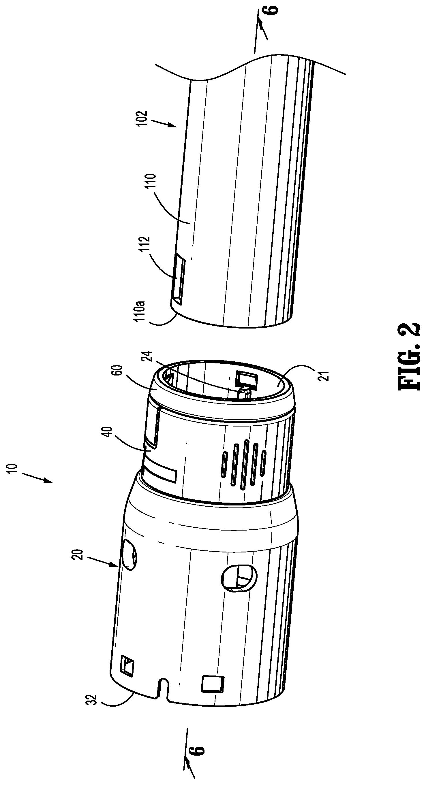
FIG. 2 is a perspective view of the adapter of FIG. 1A with the loading unit decoupled from the adapter;
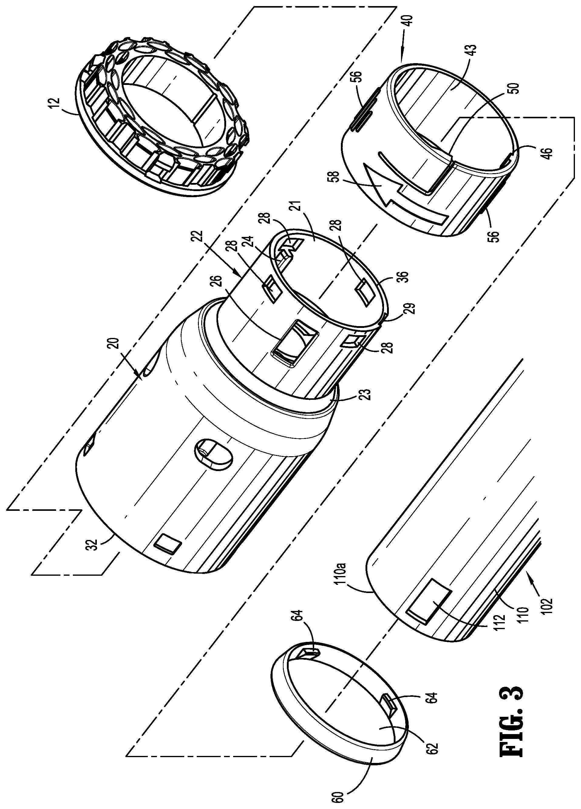
FIG. 3 is an exploded view with parts separated of the loading unit of FIG. 2;
FIG. 4 is a perspective view of a shell assembly of the loading unit of FIG. 3;
FIG. 5 is a perspective view of a locking collar of the loading unit of FIG. 3;
FIG. 6 is a longitudinal cross-sectional view of the loading unit and the distal end portion of the adapter taken along the section line 6-6 of FIG. 2;
FIG. 7 is a cross-sectional view taken along the section line 7-7 of FIG. 6;
FIG. 8 is a cross-sectional view taken along the section line 8-8 of FIG. 6;
FIG. 9 is a longitudinal cross-sectional view of the distal end portion of the adapter of FIG. 2 partially received within an annular ring of the loading unit of FIG. 2;
FIG. 10 is a cross-sectional view taken along the section line 10-10 of FIG. 9;
FIG. 11 is a longitudinal cross-sectional view of the distal end portion of the adapter of FIG. 2 received within an annular ring of the loading unit of FIG. 2;
FIG. 12 is a cross-sectional view taken along the section line 12-12 of FIG. 11;
FIG. 13 is a cross-sectional view taken along the section line 13-13 of FIG. 11;
FIG. 14 is a cross-sectional view taken along the section line 14-14 of FIG. 11;
FIG. 15 is a perspective view of the loading unit of FIG. 2 disposed over the distal end portion of the adapter with the locking collar rotated to an unlocked configuration;
FIG. 16 is a cross-sectional view taken along the section line 16-16 of FIG. 15;
FIG. 17 is a cross-sectional view taken along the section line 17-17 of FIG. 15; and
FIG. 18 is a perspective view of the loading unit of FIG. 15 released from the distal end portion of the adapter with the locking collar returned to the locked configuration.
DETAILED DESCRIPTION OF EMBODIMENTS
Embodiments of the present disclosure are now described in detail with reference to the drawings in which like reference numerals designate identical or corresponding elements in each of the several views. As used herein, the term "clinician" refers to a doctor, a nurse, or any other care provider and may include support personnel. Throughout this description, the term "proximal" refers to the portion of the device or component thereof that is closest to the clinician and the term "distal" refers to the portion of the device or component thereof that is farthest from the clinician.
This disclosure relates generally to a loading unit including a locking collar that releasably secures the loading unit to a distal end of a surgical instrument or adapter for a surgical instrument. The locking collar is rotatably disposed about the loading unit and includes a lock that has a longitudinal cam surface and a radial cam surface. The longitudinal cam surface is engaged by a distal end of the surgical instrument as the locking collar is slid over the surgical instrument to flex a flexible tab supporting a lock of the locking collar outward. When the loading unit is fully received on the distal end of the surgical instrument, a locking window of the loading unit becomes aligned with the lock. When this occurs, the resilience of the flexible tab causes the lock to move into the locking window to secure the loading unit to the distal end of the surgical instrument. The locking collar can be rotated about the loading unit such that the radial cam surface engages the loading unit to flex the flexible tab outwardly until the lock is removed from the locking window of the surgical instrument to release the loading unit from the distal end of the surgical instrument.
With reference to FIGS. 1A and 1B, a loading unit 10 is provided in accordance with embodiments of the present disclosure. The loading unit 10 is configured for selective connection to a powered hand held electromechanical instrument (not shown) via an adapter 102 of a surgical instrument. Alternatively, the loading unit 10 can be configured for connection directly to a manually actuated handle assembly or stapling instrument 700 (FIG. 1B) such as described in U.S. Pat. No. 8,789,737 ("the '737 Patent"), which is incorporated herein by reference. In the illustrated embodiment, the loading unit 10 is releasably coupled to a distal end portion 110 of the adapter 102 and includes a staple cartridge 12 (FIG. 3), a shell assembly 20, and a locking collar 40. The loading unit 10 may also include an anvil 400 (FIG. 1B). The adapter 102 is configured to translate movement of an actuator of the stapling instrument, e.g., an electromechanical actuator (not shown), to actuate the shell assembly 20 to suture and cut tissue (not shown). A proximal end 104 of the adapter 102 is attachable to the stapling instrument to actuate the staple cartridge 12. It is contemplated that the proximal end 104 of the adapter 102 may be attached to a manually actuated instrument such as described in the '737 Patent to actuate the staple cartridge 12.
For a detailed description of the structure and function of an exemplary adapter and loading unit, please refer to commonly owned U.S. Provisional Patent Application Ser. No. 62/066,518, filed Oct. 21, 2014, entitled "Adapter, Extension, and Connector Assemblies for Surgical Devices." For a detailed description of the structure and function of an exemplary electromechanical instrument, please refer to commonly owned U.S. patent application Ser. No. 13/484,975, filed on May 31, 2012, now published as U.S. Patent Publication No. 2012/0253329. Each of these applications is incorporated herein by reference in its entirety.
Referring to FIG. 2, the distal end portion 110 of surgical instrument, e.g., the adapter 102, defines a locking window 112. The locking window 112 passes through the outer surface of the distal end portion 110 of the adapter 102 and is spaced-apart from a distal end 110a of the adapter 102. The distal end portion 110 may also define a keyway 114 (FIG. 6) that extends from the distal end 110a of the adapter 102 parallel to a longitudinal axis of the adapter 102.
Referring also to FIG. 3, the loading unit 10 includes a shell assembly 20, a locking collar 40, and a retention ring 60. The shell assembly 20 has a proximal recessed annular ring 22 that defines a cylindrical opening 21 for receiving the distal end portion 110 of the adapter 102 and a distal end 32 that defines a receptacle 34 (FIG. 6) for receiving and supporting the staple cartridge 12.
Referring to FIGS. 3 and 4, the annular ring 22 of the shell assembly 20 is sized to be received through the locking collar 40 and the retention ring 60. In embodiments, the locking collar 40 has a thickness equal to the depth of a step 23 defined by the annular ring 22 such that the locking collar 40 forms a continuous or smooth surface with the outer surface of the shell assembly 20.
The annular ring 22 includes a key 24 and defines a locking slot 26 and retention slots 28. The key 24 is disposed on an inner surface of the annular ring 22 and is parallel to a longitudinal axis of the shell assembly 20. As shown, the key 24 is aligned with one of the retention slots 28; however, it is contemplated that the key 24 may be positioned between two retention slots 28.
The locking slot 26 is configured to receive a portion of the locking collar 40 to secure the shell assembly 20 to the distal end portion 110 of the adapter 102. The locking slot 26 has a substantially rectangular shape and passes between an outer surface and an inner surface of the annular ring 22. The locking slot 26 may be oriented such that the walls defining the locking slot 26 are parallel and perpendicular to the longitudinal axis of the shell assembly 20. As shown, the locking slot 26 substantially opposes the key 24. However, the locking slot 26 and the key 24 may be adjacent one another or positioned anywhere about the annular ring 22 relative to one another. The locking slot 26 is positioned between two retention slots 28 and is spaced from a proximal end 36 of the shell assembly 20 such that a proximal end of the locking slot 26 is further away from the proximal end 36 than a distal end of the retention slots 28.
The retention slots 28 are configured to receive a portion of the retention ring 60 to secure the retention ring 60 to the annular ring 22 of the shell assembly 20. As shown, the retention slots 28 are substantially rectangular in shape and are disposed about the annular ring 22. Each of the retention slots 28 are spaced an equal distance from the proximal end 36 of the shell assembly 20. As shown, the retention slots 28 are equally spaced about the annular ring 22 (i.e., at 90.degree. apart); however, it is contemplated that the retention slots 28 may be unequally spaced about the annular ring 22 to fix the orientation of the retention ring 60 with the annular ring 22 and/or the locking collar 40. Additionally or alternatively, each of the retention slots 28 may have a unique shape to fix the orientation of the retention ring 60 with the annular ring 22 and/or the locking collar 40.
With particular reference to FIG. 4, an outer surface of the annular ring 22 defines a travel groove 29. The travel groove 29 extends from the proximal end 36 of the shell assembly 20 in a direction parallel to the longitudinal axis of the shell assembly 20. The travel groove 29 has a radial dimension about the annular ring 22 as described in greater detail below.
Referring to FIG. 5, the locking collar 40 is configured to secure the shell assembly 20 to the distal end portion 110 of the adapter 102. The locking collar 40 has a resilient, cylindrical body 42 that defines a central opening 43. The body 42 includes a flexible tab 44, a travel rib 46, and a lock 50 supported on one end of the flexible tab 44. The central opening 43 is sized to rotatably receive the annular ring 22. The diameter of the central opening 43 is slightly larger than an outer diameter of the annular ring 22 to allow rotation of the locking collar 40 about the annular ring 22 with minimal resistance (e.g., resistance from friction) and to prevent excessive movement relative to the annular ring 22 due to an excess gap between the body 42 and the annular ring 22. The flexible tab 44 defines a cantilever and is formed by partially splitting the body 42 with a radial slit 48 and a longitudinal slit 49. The tab 44 may have a width that is approximately half the width of the body 42 and has a radial dimension in a range of about 45.degree. to about 90.degree. (e.g., about 75.degree.). Alternatively, other configurations are envisioned.
The lock 50 is disposed on an inner surface of the tab 44 adjacent the longitudinal slit 49 and extends into the central opening 43 of the locking collar 40. The lock 50 includes a longitudinal cam 52 and a radial cam 54. The longitudinal cam 52 is an angled surface that extends from a proximal side of the lock 50 towards a distal side of the lock 50 and towards the center of the central opening 43 to form a proximally facing wedge. The radial cam 54 is an angled surface that extends from a side of the lock 50 spaced apart from the longitudinal slit 49 and angles away from the flexible tab towards the longitudinal slit 49 and the center of the central opening 43 to form a radial wedge facing away from the longitudinal slit 49.
The travel rib 46 extends inward from the inner surface of the body 46 and is positioned adjacent the proximal end of the body 42. The travel rib 46 extends approximately halfway across the inner surface of the body 46 but may extend from the proximal end to the distal end of the body 42. The travel rib 46 is sized to be received within the travel groove 29 when the locking collar 40 is disposed about the annular ring 22 to limit rotation of the locking collar 40 about the annular ring 22 as discussed in greater detail below.
Referring briefly back to FIGS. 2 and 3, the retention ring 60 is configured to retain the locking collar 40 over the annular ring 22 (i.e., prevent the locking collar 40 from proximally translating off of the annular ring 22). The retention ring 60 defines a central opening 62 and includes retention tabs 44. The central opening 62 is sized to receive the annular ring 22. The retention tabs 64 are disposed about the inner surface of the retention ring 60 and include distally facing wedges that are configured to be received within the retention slots 28 of the annular ring 22 to radially fix the retention ring 60 to the annular ring 22 and to prevent the retention ring 60 from proximal translation relative to the annular ring 22. More specifically, when the retention ring 60 is slid over the annular ring 22, tapered surfaces of the retention tabs 64 engage a distal surface or the annular ring 22 such that the tabs 64 are deformed inwardly and pass over the annular ring 22 until the tabs 64 become aligned with the retention slots 28. When the tabs 64 become aligned with the slots 28, the tabs 64, which are resilient, spring outwardly into the retention slots 28 to secure the retention ring 60 about the annular ring 22. It is contemplated that the retention tabs 64 may also prevent distal translation of the retention ring 60 relative to the annular ring 22. The outer surface of the retention ring 60 may slope proximally to provide a smooth transition from the outer surface of the shell assembly 20 to the distal end portion 110 of the adapter 102 when the distal end portion 110 is received within the proximal opening 21 of the shell assembly 20.
Referring to FIGS. 3 and 6-8, the assembly of the adapter 102 and the shell assembly 20 of the loading unit 10 with the locking collar 40 will be described in accordance with the present disclosure. As shown in FIG. 3, the shell assembly 20 and the locking collar 40 are aligned with one another such that the longitudinal axis of the shell assembly 20 is aligned with the longitudinal axis of the locking collar 40. In addition, the locking collar 40 is rotationally aligned with the annular ring 22 of the shell assembly 20 by aligning the travel rib 46 of the locking collar 40 with the travel groove 29 of the annular ring 22. It will be appreciated that when the travel rib 46 and the travel groove 39 are rotationally aligned, the lock 50 of the locking collar 40 is substantially aligned with the locking slot 26 of the annular ring 22.
With the locking collar 40 and the annular ring 22 of the shell assembly 20 aligned with one another, the locking collar 40 is moved distally over the annular ring 22 such that the annular ring 22 is received within the central opening 43 of the locking collar 40. As the locking collar 40 is moved over the annular ring 22, the lock 50 engages the annular ring 22. Continued distal movement of the locking collar 40 over the annular ring 22 flexes the flexible tab 44 of the locking collar 40 outward such that the lock 50 of the flexible tab 44 is positioned to move along the outer surface of the annular ring 22. With the lock 50 positioned on the outer surface of the annular ring 22, the locking collar 40 is moved distally over the annular ring 22 until a distal end of the locking collar 40 abuts the step 23 defined by the annular ring 22. In this position, the lock 50 is positioned in alignment with the locking slot 26. When the distal end of the locking collar 40 abuts the step 23 as shown in FIG. 6, the resilience of the flexible tab 44 moves the lock 50 towards the longitudinal axis of the shell assembly 20 and through the locking slot 26 of the annular ring 22 to secure the locking collar 40 to the shell assembly 20 about the annular ring 22.
If the locking collar 40 is slightly misaligned with the locking slot 26 with the lock 50 extending partially through the locking slot 26 of the annular ring 22, the first or longitudinal cam surface 52 of the lock 50 engages walls defining the locking slot 26 to distally slide the locking collar 40 over the annular ring 22 and the second or radial cam surface 54 of the lock 50 engages the walls defining the locking slot 26 to rotate the locking collar 40 about the annular ring 22 to a locked configuration as shown in FIGS. 6 and 8. In the locked configuration, resilience of the flexible tab 44 urges the lock 50 through the locking slot 26 such that the lock 50 prevents rotation of the locking collar 40 about the annular ring 22 and translation of the locking collar 40 relative to the annular ring 22. In the locked configuration, the travel rib 46 of the locking collar 40 is positioned on one side of the travel groove 29 such that the travel rib 46 prevents rotation of the locking collar 40 about the annular ring 22 in a first direction (e.g., clockwise as shown in FIG. 8) and allows rotation of the locking collar 40 in a second direction opposite the first direction (e.g., counter clockwise as shown in FIG. 8). When the locking collar 40 reaches the locked configuration, the flexible tab 44 may provide audible indicia (e.g., a click) as the lock 50 passes through the locking slot 26.
With particular reference to FIGS. 6 and 7, the retention ring 60 is secured over a proximal end of the annular ring 22 proximal to the locking collar 40 to prevent the locking collar 40 from sliding proximally relative to the annular ring 22. With the locking collar 40 in the locked configuration, the retention ring 60 is slid distally over the annular ring 22 such that the annular ring 22 is received within the central opening 62 of the retention ring 60. As the retention ring 60 receives the annular ring 22, the retention tabs 64 engage the outer surface of the annular ring 22 and flex outwardly such that the retention ring 60 can pass over the annular ring 22. The retention ring 60 is positioned about the annular ring 22 such that each retention tab 64 is positioned within one of the retention slots 28 of the annular ring 22. As the retention tabs 64 are aligned with the retention slots 28, the resilience of the retention ring 60 urges the retention tabs 64 through the retention slots 28 such that the retention ring 60 is in a fixed configuration relative to the annular ring 22. When the retention ring 60 reaches the fixed configuration, the passage of the retention tabs 64 through the retention slots 28 of the retention ring 60 may provide audible indicia (e.g., a click). In the fixed configuration of the retention ring 60, the retention ring 60 is rotationally and longitudinally fixed relative to the annular ring 22. Further, in the fixed configuration, the retention ring 60 prevents the locking collar 40 from sliding proximally off the annular ring 22 of the shell assembly 20 but allows the locking collar 40 to rotate about the annular ring 22.
Each retention tab 64 is disposed within a respective retention slot 28; however, it is contemplated that each retention slot 28 may not receive a retention tab 64. As shown, the retention tabs 64 and the retention slots 28 are equally spaced about the retention ring 60 and the annular ring 22 respectively; however, it is contemplated that the retention tabs 64 and the retention slots 28 may be unequally spaced about the retention ring 60 and the annular ring 22 respectively to define a radial orientation of the retention ring 60 relative to the annular ring 22. The loading unit 10 is assembled when the locking collar 40 is in the locked configuration and the retention ring 60 is in the fixed configuration.
With reference to FIGS. 6 and 9-14, a method for securing the loading unit 10 to the distal end portion 110 of the adapter 102 or surgical instrument is disclosed in accordance with the present disclosure. Referring initially to FIG. 6, assembled loading unit 10 is aligned with the distal end portion 110 of the adapter 102 such that the longitudinal axis of the loading unit 10 is aligned with the longitudinal axis of the adapter 102. The loading unit 10 is then radially aligned with the distal end portion 110 of the adapter 102 such that the key 24 of the shell assembly 22 is aligned with the keyway 114 of the distal end portion 110 as shown in FIG. 6. When the key 24 and the keyway 114 are radially aligned, the locking slot 26 of the shell assembly 22 is radially aligned with the lock window 112 of the distal end portion 110 of the adapter 102.
Referring now to FIGS. 9 and 10, with the loading unit 10 and the distal end portion 110 of the adapter 102 aligned with one another, the loading unit 10 is slid over the distal end portion 110 of the adapter 102 such that the distal end portion 110 of the adapter 102 is at least partially disposed within the proximal opening 21 of the shell assembly 20. As the distal end portion 110 of the adapter 102 slides into the proximal opening 21, the key 24 slides in the keyway 114 of the distal end portion 110. Further, as the distal end portion 110 of the adapter 102 slides into the proximal opening 21, the distal end 110a of the adapter 102 adjacent the locking slot 112 engages the lateral cam surface 52 of the lock 50 to urge the lock 50 and the flexible tab 40 outward. The loading unit 10 is slid over the distal end portion 110 of the adapter 102 until the lock window 112 of the adapter 102 is longitudinally aligned with the locking slot 26 of the annular ring 22 of the shell assembly 20. When lock window 112 and the locking slot 26 are aligned, the resilience of the flexible tab 44 urges or snaps the lock 50 through the lock window 112 of the adapter 102 and into the locked configuration as shown in FIG. 11. When the lock 50 reaches the locked configuration, the lock 50 may provide audible indicia (e.g., a click) to a user.
As shown in FIGS. 11-14, the loading unit 10 is secured to the distal end portion 110 of the adapter 102 when the distal end portion 110 of the adapter 102 is positioned within the proximal opening 21 of the shell assembly 20 with the lock 50 disposed in the lock window 112 in the locked configuration. With the loading unit 10 secured to the distal end portion 110 of the adapter 102, the surgical instrument and loading unit 10 may be used to perform a surgical procedure. After surgical procedure is completed, the loading unit 10 can be decoupled or detached from the surgical instrument as will be discussed in detail below. With the loading unit 10 decoupled from the surgical instrument, another loading unit may be coupled or secured to the surgical instrument for continued use in the surgical procedure, the surgical instrument may be sterilized for use in another surgical procedure, or the surgical instrument may be discarded. In addition, the loading unit 10 may be sterilized for use in another surgical procedure or may be discarded.
With reference to FIGS. 15-18, a method for detaching the loading unit 10 from the distal end portion 110 of the adapter 102 or surgical instrument is disclosed in accordance with the present disclosure. To detach the loading unit 10, the body 42 of the locking collar 40 is rotated about the annular ring 22 of the shell assembly 20 such that the lock 50 is moved outward and from within of the lock window 112 of the adapter 102 to release the distal end portion 110 of the adapter 102 from the loading unit 10. Specifically, the body 42 of the locking collar 40 is rotated about the annular ring 22 in the direction indicated by arrow "R". The outer surface of the body 42 may include engagement features 56 to provide a clinician a grip for rotating the body 42. With particular reference to FIGS. 16 and 17, as the body 42 is rotated in the direction of arrow "R", the second cam surface 54 of the lock 50 engages the walls defining the locking slot 36 to move or cam the lock 50 outward to an unlocked configuration. When the lock 50 is in the unlocked configuration, the loading unit 10 is distally slidable to release or detach the distal end portion 110 of the adapter 102 from the loading unit 10 as shown in FIG. 18. When the loading unit 10 is detached from the distal end portion 110, the body 42 is released such that the resilience of the body 42 and the flexible tab 44 return the locking collar 40 to the locked configuration.
As the body 42 of the locking collar 40 is rotated about the distal end portion 110 of the adapter 102, the key 24 and the keyway 114 prevent the shell assembly 20 from rotating relative to the adapter 102. Further, as detailed above, the retention tabs 64 and the retention slots 28 prevent the retention ring 60 from rotating about the shell assembly 20.
With particular reference to FIG. 16, the travel rib 46 prevents over rotation of the body 42 of the locking collar 40 about the annular ring 22. Specifically, as the body 42 is rotated about the annular ring 22, the travel rib 46 moves from the fixed configuration (FIG. 13) to a released configuration within the travel groove 29 as shown in FIG. 16. When the travel rib 46 is in the released configuration, the lock 50 is outside of the lock window 112 of the adapter 102 and may be substantially out of the locking slot 26 of the annular ring 22. The travel rib 46 prevents over rotation of the body 42 about the annular ring 22 to a point where the resilience of the body 42 is unable to return the lock 50 to the locked configuration.
The locking collar 40 is made of a resilient material. For example, the locking collar 12 may be formed of a resilient plastic material using an injection molding process. However, it is contemplated the locking collar 40 may be formed of other suitable materials including, but not limited to, spring steel, stainless steel, or wire.
While several embodiments of the disclosure have been shown in the drawings, it is not intended that the disclosure be limited thereto, as it is intended that the disclosure be as broad in scope as the art will allow and that the specification be read likewise. Any combination of the above embodiments is also envisioned and is within the scope of the appended claims. The present disclosure is not limited to circular stapling loading units, but has application to loading units for linear stapling or other types of instruments, such as electrocautery or ultrasonic instruments.
Therefore, the above description should not be construed as limiting, but merely as exemplifications of particular embodiments. Those skilled in the art will envision other modifications within the scope of the claims appended hereto.
* * * * *
D00000
D00001
D00002
D00003
D00004
D00005
D00006
D00007
D00008
D00009
D00010
D00011
D00012

XML
uspto.report is an independent third-party trademark research tool that is not affiliated, endorsed, or sponsored by the United States Patent and Trademark Office (USPTO) or any other governmental organization. The information provided by uspto.report is based on publicly available data at the time of writing and is intended for informational purposes only.
While we strive to provide accurate and up-to-date information, we do not guarantee the accuracy, completeness, reliability, or suitability of the information displayed on this site. The use of this site is at your own risk. Any reliance you place on such information is therefore strictly at your own risk.
All official trademark data, including owner information, should be verified by visiting the official USPTO website at www.uspto.gov. This site is not intended to replace professional legal advice and should not be used as a substitute for consulting with a legal professional who is knowledgeable about trademark law.