Quad-sector antenna using circular polarization
Hinman A
U.S. patent number 10,742,275 [Application Number 14/198,473] was granted by the patent office on 2020-08-11 for quad-sector antenna using circular polarization. This patent grant is currently assigned to Mimosa Networks, Inc.. The grantee listed for this patent is Brian L. Hinman. Invention is credited to Brian L. Hinman.

| United States Patent | 10,742,275 |
| Hinman | August 11, 2020 |
Quad-sector antenna using circular polarization
Abstract
Systems and methods for providing a MIMO capable antenna with unique properties are provided herein. In some embodiments, a 4.times.4 MIMO capable antenna is provided with unique properties. Circular polarization from the antennas ensures that both vertical and horizontal polarizations are energized to the full extent provided by local regulations. A system includes a radio and a plurality of antennas coupled to the radio, the plurality of antennas servicing a broadcast area that has a 360 degree coverage area. Each of the plurality of antennas transmits and receives in an isolated sub-sector of the 360 degree coverage area.
| Inventors: | Hinman; Brian L. (Los Gatos, CA) | ||||||||||
|---|---|---|---|---|---|---|---|---|---|---|---|
| Applicant: |
|
||||||||||
| Assignee: | Mimosa Networks, Inc. (Santa
Clara, CA) |
||||||||||
| Family ID: | 51487209 | ||||||||||
| Appl. No.: | 14/198,473 | ||||||||||
| Filed: | March 5, 2014 |
Prior Publication Data
| Document Identifier | Publication Date | |
|---|---|---|
| US 20140253378 A1 | Sep 11, 2014 | |
Related U.S. Patent Documents
| Application Number | Filing Date | Patent Number | Issue Date | ||
|---|---|---|---|---|---|
| 61774323 | Mar 7, 2013 | ||||
| Current U.S. Class: | 1/1 |
| Current CPC Class: | H04B 7/10 (20130101); H01Q 21/08 (20130101); H01Q 21/24 (20130101); H01Q 11/08 (20130101); H04B 7/0452 (20130101); H01Q 21/28 (20130101); H01Q 21/205 (20130101) |
| Current International Class: | H04B 7/0452 (20170101); H04B 7/10 (20170101); H01Q 21/08 (20060101); H01Q 21/28 (20060101); H01Q 21/20 (20060101); H01Q 11/08 (20060101); H01Q 21/24 (20060101) |
| Field of Search: | ;342/361,350 |
References Cited [Referenced By]
U.S. Patent Documents
| 2735993 | February 1956 | Humphrey |
| 3182129 | May 1965 | Clark et al. |
| D227476 | June 1973 | Kennedy |
| 4188633 | February 1980 | Frazita |
| 4402566 | September 1983 | Powell et al. |
| D273111 | March 1984 | Hirata et al. |
| 4543579 | September 1985 | Teshirogi |
| 4562416 | December 1985 | Sedivec |
| 4626863 | December 1986 | Knop et al. |
| 4835538 | May 1989 | McKenna et al. |
| 4866451 | September 1989 | Chen |
| 4893288 | January 1990 | Maier et al. |
| 4903033 | February 1990 | Tsao |
| 4986764 | January 1991 | Eaby et al. |
| 5015195 | May 1991 | Piriz |
| 5226837 | July 1993 | Cinibulk et al. |
| 5231406 | July 1993 | Sreenivas |
| D346598 | May 1994 | McCay et al. |
| D355416 | February 1995 | McCay et al. |
| 5389941 | February 1995 | Yu |
| 5491833 | February 1996 | Hamabe |
| 5513380 | April 1996 | Ivanov et al. |
| 5539361 | July 1996 | Davidovitz |
| 5561434 | October 1996 | Yamazaki |
| D375501 | November 1996 | Lee et al. |
| 5580264 | December 1996 | Aoyama et al. |
| 5684495 | November 1997 | Dyott et al. |
| D389575 | January 1998 | Grasfield et al. |
| 5724666 | March 1998 | Dent |
| 5742911 | April 1998 | Dumbrill |
| 5746611 | May 1998 | Brown et al. |
| 5764696 | June 1998 | Barnes |
| 5797083 | August 1998 | Anderson |
| 5831582 | November 1998 | Muhlhauser |
| 5966102 | October 1999 | Runyon |
| 5995063 | November 1999 | Somoza et al. |
| 6014372 | January 2000 | Kent et al. |
| 6067053 | May 2000 | Runyon et al. |
| 6137449 | October 2000 | Kildal |
| 6140962 | October 2000 | Groenenboom |
| 6176739 | January 2001 | Denlinger et al. |
| 6216266 | April 2001 | Eastman et al. |
| 6271802 | August 2001 | Clark |
| 6304762 | October 2001 | Myers |
| D455735 | April 2002 | Winslow |
| 6421538 | July 2002 | Byrne |
| 6716063 | April 2004 | Bryant et al. |
| 6754511 | June 2004 | Halford et al. |
| 6847653 | January 2005 | Smiroldo |
| D501848 | February 2005 | Uehara et al. |
| 6853336 | February 2005 | Asano et al. |
| 6864837 | March 2005 | Runyon et al. |
| 6877277 | April 2005 | Kussel et al. |
| 6962445 | November 2005 | Zimmel et al. |
| 7075492 | July 2006 | Chen et al. |
| D533899 | December 2006 | Ohashi et al. |
| 7173570 | February 2007 | Wensink |
| 7187328 | March 2007 | Tanaka et al. |
| 7193562 | March 2007 | Shtrom |
| 7212162 | May 2007 | Jung et al. |
| 7212163 | May 2007 | Huang |
| 7245265 | July 2007 | Kienzle et al. |
| 7253783 | August 2007 | Chiang |
| 7264494 | September 2007 | Kennedy et al. |
| 7281856 | October 2007 | Grzegorzewska et al. |
| 7292198 | November 2007 | Shtrom |
| 7306485 | December 2007 | Masuzaki |
| 7316583 | January 2008 | Mistarz |
| 7324057 | January 2008 | Argaman et al. |
| D566698 | April 2008 | Choi et al. |
| 7362236 | April 2008 | Hoiness |
| 7369095 | May 2008 | Hirtzlin et al. |
| 7380984 | June 2008 | Wuester |
| 7431602 | October 2008 | Corona |
| 7498896 | March 2009 | Shi |
| 7498996 | March 2009 | Shtrom |
| 7507105 | March 2009 | Peters et al. |
| 7522095 | April 2009 | Wasiewicz et al. |
| 7542717 | June 2009 | Green, Sr. et al. |
| 7581976 | September 2009 | Liepold et al. |
| 7586891 | September 2009 | Masciulli |
| 7616959 | November 2009 | Spenik et al. |
| 7646343 | January 2010 | Shtrom |
| 7675473 | March 2010 | Kienzle et al. |
| 7675474 | March 2010 | Shtrom |
| 7726997 | June 2010 | Kennedy et al. |
| 7778226 | August 2010 | Rayzman et al. |
| 7857523 | December 2010 | Masuzaki |
| 7929914 | April 2011 | Tegreene |
| RE42522 | July 2011 | Zimmel et al. |
| 8009646 | August 2011 | Lastinger |
| 8069465 | November 2011 | Bartholomay et al. |
| 8111678 | February 2012 | Lastinger |
| 8254844 | August 2012 | Kuffner |
| 8270383 | September 2012 | Lastinger |
| 8275265 | September 2012 | Kobyakov et al. |
| 8325695 | December 2012 | Lastinger |
| D674787 | January 2013 | Tsuda et al. |
| 8345651 | January 2013 | Lastinger |
| 8385305 | February 2013 | Negus |
| 8425260 | April 2013 | Seefried et al. |
| 8482478 | July 2013 | Hartenstein |
| 8515434 | August 2013 | Narendran et al. |
| 8515495 | August 2013 | Shang |
| D694740 | December 2013 | Apostolakis |
| 8777660 | July 2014 | Chiarelli et al. |
| 8792759 | July 2014 | Benton et al. |
| 8827729 | September 2014 | Gunreben et al. |
| 8836601 | September 2014 | Sanford et al. |
| 8848389 | September 2014 | Kawamura et al. |
| 8870069 | October 2014 | Bellows |
| 8935122 | January 2015 | Stisser |
| 9001689 | April 2015 | Hinman et al. |
| 9019874 | April 2015 | Choudhury et al. |
| 9077071 | July 2015 | Shtrom |
| 9107134 | August 2015 | Belser et al. |
| 9130305 | September 2015 | Ramos et al. |
| 9161387 | October 2015 | Fink et al. |
| 9179336 | November 2015 | Fink et al. |
| 9191081 | November 2015 | Hinman et al. |
| D752566 | March 2016 | Hinman et al. |
| 9295103 | March 2016 | Fink et al. |
| 9362629 | June 2016 | Hinman et al. |
| 9391375 | July 2016 | Bales |
| 9407012 | August 2016 | Shtrom |
| 9431702 | August 2016 | Hartenstein |
| 9504049 | November 2016 | Hinman et al. |
| 9531114 | December 2016 | Ramos et al. |
| 9537204 | January 2017 | Cheng |
| 9577340 | February 2017 | Fakharzadeh et al. |
| 9693388 | June 2017 | Fink et al. |
| 9780892 | October 2017 | Hinman et al. |
| 9843940 | December 2017 | Hinman et al. |
| 9871302 | January 2018 | Hinman et al. |
| 9888485 | February 2018 | Hinman et al. |
| 9930592 | March 2018 | Hinman |
| 9949147 | April 2018 | Hinman et al. |
| 9986565 | May 2018 | Fink et al. |
| 9998246 | June 2018 | Hinman et al. |
| 10028154 | July 2018 | Elson |
| 10090943 | October 2018 | Hinman et al. |
| 10096933 | October 2018 | Ramos et al. |
| 10117114 | October 2018 | Hinman et al. |
| 10186786 | January 2019 | Hinman et al. |
| 10200925 | February 2019 | Hinman |
| 10257722 | April 2019 | Hinman et al. |
| 10425944 | September 2019 | Fink et al. |
| 10447417 | October 2019 | Hinman et al. |
| 10511074 | December 2019 | Eberhardt et al. |
| 10595253 | March 2020 | Hinman |
| 10616903 | April 2020 | Hinman et al. |
| 2001/0033600 | October 2001 | Yang |
| 2002/0102948 | August 2002 | Stanwood et al. |
| 2002/0159434 | October 2002 | Gosior et al. |
| 2003/0013452 | January 2003 | Hunt et al. |
| 2003/0027577 | February 2003 | Brown et al. |
| 2003/0169763 | September 2003 | Choi et al. |
| 2003/0222831 | December 2003 | Dunlap |
| 2003/0224741 | December 2003 | Sugar et al. |
| 2004/0002357 | January 2004 | Benveniste |
| 2004/0029549 | February 2004 | Fikart |
| 2004/0110469 | June 2004 | Judd et al. |
| 2004/0120277 | June 2004 | Holur et al. |
| 2004/0155819 | August 2004 | Martin et al. |
| 2004/0196812 | October 2004 | Barber |
| 2004/0196813 | October 2004 | Ofek |
| 2004/0240376 | December 2004 | Wang et al. |
| 2004/0242274 | December 2004 | Corbett |
| 2005/0012665 | January 2005 | Runyon et al. |
| 2005/0032479 | February 2005 | Miller et al. |
| 2005/0058111 | March 2005 | Hung |
| 2005/0124294 | June 2005 | Wentink |
| 2005/0143014 | June 2005 | Li et al. |
| 2005/0195758 | September 2005 | Chitrapu |
| 2005/0227625 | October 2005 | Diener |
| 2005/0254442 | November 2005 | Proctor, Jr. et al. |
| 2005/0271056 | December 2005 | Kaneko |
| 2005/0275527 | December 2005 | Kates |
| 2006/0025072 | February 2006 | Pan |
| 2006/0072518 | April 2006 | Pan et al. |
| 2006/0098592 | May 2006 | Proctor, Jr. et al. |
| 2006/0099940 | May 2006 | Pfleging et al. |
| 2006/0132359 | June 2006 | Chang |
| 2006/0132602 | June 2006 | Muto et al. |
| 2006/0172578 | August 2006 | Parsons |
| 2006/0187952 | August 2006 | Kappes et al. |
| 2006/0211430 | September 2006 | Persico |
| 2006/0276073 | December 2006 | McMurray et al. |
| 2007/0001910 | January 2007 | Yamanaka et al. |
| 2007/0019664 | January 2007 | Benveniste |
| 2007/0035463 | February 2007 | Hirabayashi |
| 2007/0060158 | March 2007 | Medepalli et al. |
| 2007/0132643 | June 2007 | Durham et al. |
| 2007/0173199 | July 2007 | Sinha |
| 2007/0173260 | July 2007 | Love et al. |
| 2007/0202809 | August 2007 | Lastinger et al. |
| 2007/0210974 | September 2007 | Chiang |
| 2007/0223701 | September 2007 | Emeott et al. |
| 2007/0238482 | October 2007 | Rayzman et al. |
| 2007/0255797 | November 2007 | Dunn et al. |
| 2007/0268848 | November 2007 | Khandekar et al. |
| 2008/0109051 | May 2008 | Splinter et al. |
| 2008/0112380 | May 2008 | Fischer |
| 2008/0192707 | August 2008 | Xhafa et al. |
| 2008/0218418 | September 2008 | Gillette |
| 2008/0231541 | September 2008 | Teshirogi et al. |
| 2008/0242342 | October 2008 | Rofougaran |
| 2009/0046673 | February 2009 | Kaidar |
| 2009/0052362 | February 2009 | Meier et al. |
| 2009/0059794 | March 2009 | Frei |
| 2009/0075606 | March 2009 | Shtrom |
| 2009/0096699 | April 2009 | Chiu et al. |
| 2009/0232026 | September 2009 | Lu |
| 2009/0233475 | September 2009 | Mildon et al. |
| 2009/0291690 | November 2009 | Guvenc et al. |
| 2009/0315792 | December 2009 | Miyashita et al. |
| 2010/0029282 | February 2010 | Stamoulis et al. |
| 2010/0039340 | February 2010 | Brown |
| 2010/0046650 | February 2010 | Jongren et al. |
| 2010/0067505 | March 2010 | Fein et al. |
| 2010/0085950 | April 2010 | Sekiya et al. |
| 2010/0091818 | April 2010 | Sen et al. |
| 2010/0103065 | April 2010 | Shtrom et al. |
| 2010/0103066 | April 2010 | Shtrom et al. |
| 2010/0136978 | June 2010 | Cho et al. |
| 2010/0151877 | June 2010 | Lee et al. |
| 2010/0167719 | July 2010 | Sun |
| 2010/0171665 | July 2010 | Nogami |
| 2010/0171675 | July 2010 | Borja et al. |
| 2010/0189005 | July 2010 | Bertani et al. |
| 2010/0202613 | August 2010 | Ray et al. |
| 2010/0210147 | August 2010 | Hauser |
| 2010/0216412 | August 2010 | Rofougaran |
| 2010/0225529 | September 2010 | Landreth |
| 2010/0238083 | September 2010 | Malasani |
| 2010/0304680 | December 2010 | Kuffner |
| 2010/0311321 | December 2010 | Norin |
| 2010/0315307 | December 2010 | Syed et al. |
| 2010/0322219 | December 2010 | Fischer et al. |
| 2011/0006956 | January 2011 | McCown |
| 2011/0028097 | February 2011 | Memik et al. |
| 2011/0032159 | February 2011 | Wu et al. |
| 2011/0044186 | February 2011 | Jung et al. |
| 2011/0090129 | April 2011 | Weily et al. |
| 2011/0103309 | May 2011 | Wang et al. |
| 2011/0111715 | May 2011 | Buer et al. |
| 2011/0112717 | May 2011 | Resner |
| 2011/0133996 | June 2011 | Alapuranen |
| 2011/0170424 | July 2011 | Safavi |
| 2011/0172916 | July 2011 | Pakzad et al. |
| 2011/0182260 | July 2011 | Sivakumar et al. |
| 2011/0182277 | July 2011 | Shapira |
| 2011/0194644 | August 2011 | Liu et al. |
| 2011/0206012 | August 2011 | Youn et al. |
| 2011/0241969 | October 2011 | Zhang et al. |
| 2011/0243291 | October 2011 | McAllister et al. |
| 2011/0256874 | October 2011 | Hayama et al. |
| 2011/0291914 | December 2011 | Lewry et al. |
| 2012/0008542 | January 2012 | Koleszar et al. |
| 2012/0040700 | February 2012 | Gomes et al. |
| 2012/0057533 | March 2012 | Junell et al. |
| 2012/0093091 | April 2012 | Kang et al. |
| 2012/0115487 | May 2012 | Josso |
| 2012/0134280 | May 2012 | Rotvold et al. |
| 2012/0140651 | June 2012 | Nicoara et al. |
| 2012/0238201 | September 2012 | Du et al. |
| 2012/0263145 | October 2012 | Marinier et al. |
| 2012/0282868 | November 2012 | Hahn |
| 2012/0299789 | November 2012 | Orban et al. |
| 2012/0314634 | December 2012 | Sekhar |
| 2013/0003645 | January 2013 | Shapira et al. |
| 2013/0005350 | January 2013 | Campos et al. |
| 2013/0023216 | January 2013 | Moscibroda et al. |
| 2013/0044028 | February 2013 | Lea |
| 2013/0064161 | March 2013 | Hedayat et al. |
| 2013/0082899 | April 2013 | Gomi |
| 2013/0095747 | April 2013 | Moshfeghi |
| 2013/0128858 | May 2013 | Zou et al. |
| 2013/0176902 | July 2013 | Wentink et al. |
| 2013/0182652 | July 2013 | Tong et al. |
| 2013/0195081 | August 2013 | Merlin et al. |
| 2013/0210457 | August 2013 | Kummetz |
| 2013/0223398 | August 2013 | Li |
| 2013/0234898 | September 2013 | Leung et al. |
| 2013/0271319 | October 2013 | Trerise |
| 2013/0286950 | October 2013 | Pu |
| 2013/0286959 | October 2013 | Lou et al. |
| 2013/0288735 | October 2013 | Guo |
| 2013/0301438 | November 2013 | Li et al. |
| 2013/0322276 | December 2013 | Pelletier et al. |
| 2013/0322413 | December 2013 | Pelletier et al. |
| 2014/0024328 | January 2014 | Balbien et al. |
| 2014/0051357 | February 2014 | Steer et al. |
| 2014/0098748 | April 2014 | Chan et al. |
| 2014/0113676 | April 2014 | Hamalainen et al. |
| 2014/0145890 | May 2014 | Ramberg et al. |
| 2014/0154895 | June 2014 | Poulsen et al. |
| 2014/0185494 | July 2014 | Yang et al. |
| 2014/0191918 | July 2014 | Cheng et al. |
| 2014/0198867 | July 2014 | Sturkovich et al. |
| 2014/0206322 | July 2014 | Dimou et al. |
| 2014/0225788 | August 2014 | Schulz et al. |
| 2014/0233613 | August 2014 | Fink et al. |
| 2014/0235244 | August 2014 | Hinman |
| 2014/0253402 | September 2014 | Hinman et al. |
| 2014/0254700 | September 2014 | Hinman et al. |
| 2014/0256166 | September 2014 | Ramos et al. |
| 2014/0320306 | October 2014 | Winter |
| 2014/0320377 | October 2014 | Cheng et al. |
| 2014/0328238 | November 2014 | Seok et al. |
| 2014/0355578 | December 2014 | Fink et al. |
| 2014/0355584 | December 2014 | Fink et al. |
| 2015/0002335 | January 2015 | Hinman |
| 2015/0002354 | January 2015 | Knowles |
| 2015/0015435 | January 2015 | Shen et al. |
| 2015/0116177 | April 2015 | Powell et al. |
| 2015/0156642 | June 2015 | Sobczak et al. |
| 2015/0215952 | July 2015 | Hinman et al. |
| 2015/0256275 | September 2015 | Hinman et al. |
| 2015/0263816 | September 2015 | Hinman et al. |
| 2015/0319584 | November 2015 | Fink et al. |
| 2015/0321017 | November 2015 | Perryman et al. |
| 2015/0325945 | November 2015 | Ramos et al. |
| 2015/0327272 | November 2015 | Fink et al. |
| 2015/0365866 | December 2015 | Hinman et al. |
| 2016/0119018 | April 2016 | Lindgren et al. |
| 2016/0149634 | May 2016 | Kalkunte |
| 2016/0149635 | May 2016 | Hinman et al. |
| 2016/0211583 | July 2016 | Lee et al. |
| 2016/0240929 | August 2016 | Hinman et al. |
| 2016/0338076 | November 2016 | Hinman et al. |
| 2016/0365666 | December 2016 | Ramos et al. |
| 2016/0366601 | December 2016 | Hinman et al. |
| 2017/0048647 | February 2017 | Jung et al. |
| 2017/0201028 | July 2017 | Eberhardt et al. |
| 2017/0238151 | August 2017 | Fink et al. |
| 2017/0294975 | October 2017 | Hinman et al. |
| 2018/0034166 | February 2018 | Hinman |
| 2018/0035317 | February 2018 | Hinman et al. |
| 2018/0083365 | March 2018 | Hinman et al. |
| 2018/0084563 | March 2018 | Hinman et al. |
| 2018/0160353 | June 2018 | Hinman |
| 2018/0192305 | July 2018 | Hinman et al. |
| 2018/0199345 | July 2018 | Fink et al. |
| 2018/0241491 | August 2018 | Hinman et al. |
| 2019/0006789 | January 2019 | Ramos et al. |
| 2019/0182686 | June 2019 | Hinman et al. |
| 2019/0214699 | July 2019 | Eberhardt et al. |
| 2019/0215745 | July 2019 | Hinman |
| 2019/0273326 | September 2019 | Sanford et al. |
| 2020/0015231 | January 2020 | Fink et al. |
| 2020/0036465 | January 2020 | Hinman et al. |
| 2020/0067164 | February 2020 | Eberhardt et al. |
| 2020/0083614 | March 2020 | Sanford et al. |
| 303453662 | Nov 2015 | CN | |||
| 105191204 | Dec 2015 | CN | |||
| 105191204 | May 2019 | CN | |||
| 002640177 | Feb 2015 | EP | |||
| 3491697 | Jun 2019 | EP | |||
| WO2014137370 | Sep 2014 | WO | |||
| WO2014138292 | Sep 2014 | WO | |||
| WO2014193394 | Dec 2014 | WO | |||
| WO2015112627 | Jul 2015 | WO | |||
| WO2017123558 | Jul 2017 | WO | |||
| WO2018022526 | Feb 2018 | WO | |||
| WO2019136257 | Jul 2019 | WO | |||
| WO2019168800 | Sep 2019 | WO | |||
Other References
|
Final Office Action, dated Oct. 17, 2016, U.S. Appl. No. 14/639,976, filed Mar. 5, 2015. cited by applicant . Non-Final Office Action, dated Oct. 26, 2016, U.S. Appl. No. 15/139,225, filed Apr. 26, 2016. cited by applicant . Notice of Allowance, dated Jul. 26, 2016, U.S. Appl. No. 14/325,307, filed Jul. 7, 2014. cited by applicant . Notice of Allowance, dated Aug. 16, 2016, U.S. Appl. No. 14/802,829, filed Jul. 17, 2015. cited by applicant . International Search Report and Written Opinion of the International Search Authority dated Jul. 1, 2014 in Patent Cooperation Treaty Application No. PCT/US2014/020880, filed Mar. 5, 2014. cited by applicant . Non-Final Office Action, dated Sep. 15, 2016, U.S. Appl. No. 14/183,375, filed Feb. 18, 2014. cited by applicant . Non-Final Office Action, dated Sep. 30, 2016, U.S. Appl. No. 14/657,942, filed Mar. 13, 2015. cited by applicant . Final Office Action, dated Oct. 12, 2016, U.S. Appl. No. 14/741,423, filed Jun. 16, 2015. cited by applicant . "International Search Report" and "Written Opinion of the International Search Authority," dated May 23, 2019 in Patent Cooperation Treaty Application No. PCT/US2019/019462, filed Feb. 25, 2019, 8 pages. cited by applicant . Teshirogi, Tasuku et al., "Wideband Circularly Polarized Array Antenna with Sequential Rotations and Phase Shift of Elements," Proceedings of the International Symposium on Antennas and Propagation, 1985, pp. 117-120. cited by applicant . "Sector Antennas," Radiowaves.com, [online], [retrieved Oct. 10, 2019], Retrieved from the Internet: <URL:https://www.radiowaves.com/en/products/sector-antennas>, 4 pages. cited by applicant . KP Performance Antennas Search Results for Antennas, Sector, Single, [online], KPPerformance.com [retrieved Oct. 10, 2019], Retrieved from the Internet: <URL:https://www.kpperformance.com/search?Category=Antennas&- Rfpsan99design=Sector&Rfpsan99option=Single&view_type=grid>, 6 pages. cited by applicant . Notice of Allowance dated Sep. 8, 2015 in Chinese Design Patent Application 201530058063.8, filed Mar. 11, 2015. cited by applicant . "Notice of Allowance," Chinese Patent Application No. 201580000078.6, dated Feb. 11, 2019, 2 pages. cited by applicant . "International Search Report" and "Written Opinion of the International Search Authority," dated Mar. 22, 2019 in Patent Cooperation Treaty Application No. PCT/US2019/012358, filed Jan. 4, 2019, 9 pages. cited by applicant . FCC Regulations, 47 CFR .sctn. 15.407, 63 FR 40836, Jul. 31, 1998, as amended at 69 FR 2687, Jan. 20, 2004; 69 FR 54036, Sep. 7, 2004; pp. 843-846. cited by applicant . Weisstein, Eric, "Electric Polarization", Wolfram Reasearch [online], Retrieved from the Internet [retrieved Mar. 23, 2017] <URL:http://scienceworld.wolfram.com/physics/ElectricPolarization.html- >, 2007, 1 page. cited by applicant . Liu, Lingjia et al., "Downlink MIMO in LTE-Advanced: SU-MIMO vs. MU-MIMO," IEEE Communications Magazine, Feb. 2012, pp. 140-147. cited by applicant . "International Search Report" and "Written Opinion of the International Searching Authority," Patent Cooperation Treaty Application No. PCT/US2017/012884, dated Apr. 6, 2017, 9 pages. cited by applicant . International Search Report and Written Opinion of the International Search Authority dated Nov. 26, 2013 in Patent Cooperation Treaty Application No. PCT/US2013/047406, filed Jun. 24, 2013. cited by applicant . International Search Report and Written Opinion of the International Search Authority dated Aug. 9, 2013 in Patent Cooperation Treaty Application No. PCT/US2013/043436, filed May 30, 2013. cited by applicant . "Office Action," Chinese Patent Application No. 201580000078.6, dated Nov. 3, 2017, 5 pages [10 pages including translation]. cited by applicant . "International Search Report" and "Written Opinion of the International Searching Authority," Patent Cooperation Treaty Application No. PCT/US2017/043560, dated Nov. 16, 2017, 11 pages. cited by applicant . International Search Report and Written Opinion of the International Search Authority dated Jun. 29, 2015 in Patent Cooperation Treaty Application No. PCT/US2015/012285, filed Jan. 21, 2015. cited by applicant . Hinman et al., U.S. Appl. No. 61/774,632, filed Mar. 7, 2013. cited by applicant . First Official Notification dated Jun. 15, 2015 in Chinese Design Patent Application 201530058063.8, filed Mar. 11, 2015. cited by applicant . "Office Action," Chinese Patent Application No. 201580000078.6, dated Jul. 30, 2018, 5 pages [11 pages including translation]. cited by applicant . "Office Action," Chinese Patent Application No. 201580000078.6, dated Oct. 31, 2018, 3 pages [6 pages including translation]. cited by applicant . "Partial Supplemental European Search Report," European Patent Application No. 17835073.2, dated Feb. 13, 2020, 17 pages. cited by applicant . "Wireless Access Point," Wikipedia.org, Jan. 6, 2020 [retrieved on Feb. 3, 2020], Retrieved from the Internet: <https://en.wikipedia.org/wiki/Wireless_access_point>, 5 pages. cited by applicant. |
Primary Examiner: Magloire; Vladimir
Assistant Examiner: Pervin; Nuzhat
Attorney, Agent or Firm: Carr & Ferrell LLP
Parent Case Text
CROSS REFERENCE TO RELATED APPLICATIONS
This application claims the priority benefit of U.S. Provisional Application No. 61/774,323, filed on Mar. 7, 2013, which is hereby incorporated by reference herein in its entirety including all reference cited therein.
Claims
What is claimed is:
1. A MIMO system comprising: a radio; and at least four antennas coupled to the radio, the at least four antennas servicing a broadcast area that has a 360 degree coverage area, wherein each of the at least four antennas transmits and receives in a sub-sector of the 360 degree coverage area, wherein a first of the at least four antennas transmits and receives signals in a first isolated sub-sector using a primary right-handed circular polarization and comprises a first angular orientation, a second of the at least four antennas transmits and receives signals in a second isolated sub-sector using a secondary left-handed circular orthogonal polarization and has a second angular orientation, a third of the at least four antennas transmits and receives signals in a third isolated sub-sector using the primary right-handed circular polarization and has a third angular orientation, and a fourth of the at least four antennas transmits and receives signals in a fourth isolated sub-sector using the secondary left-handed circular orthogonal polarization and has a fourth angular orientation, wherein the first angular orientation and the second angular orientation are selected to allow the first and the second of the at least four antennas to broadcast orthogonally relative to one another, wherein the at least four antennas are capable of providing circular polarization diversity in both transmission and reception allowing the radio to flood all polarizations using reverse polarization to provide additional power, and wherein the first and third of the at least four antennas are disposed 180 degrees out of phase relative to one another and the second and fourth of the at least four antennas are disposed 180 degrees out of phase relative to one another.
2. The MIMO system according to claim 1, wherein the first, second, third, and fourth isolated sub-sectors each occupy approximately 90 degrees of the 360 degree coverage area.
3. The MIMO system according to claim 1, wherein the additional power is approximately double.
Description
FIELD OF THE INVENTION
The present technology is generally described as providing quad-sector antenna that use circular polarization. According to some embodiments, the present technology is directed to systems and methods for providing a MIMO capable antenna with unique properties. In some embodiments, a 4.times.4 MIMO capable antenna is provided with unique properties. The use of circular polarization by the antennas ensures that both vertical and horizontal polarizations are energized to the full extent provided by local regulations.
BACKGROUND
MIMO systems in general utilize multiple antennas at both the transmitter and receiver to improve communication performance. While not necessarily scaling linearly with antenna count, MIMO systems allow for the communication of different information on each of a plurality of antennas, generally using the same frequency, allowing a new dimension of scalability in high throughput communication. These MIMO systems exploit the use of spatial, polarization, time and/or frequency diversity to achieve orthogonality between multiple data streams transmitted simultaneously. Advanced downlink multi-user MIMO (MU-MIMO) systems takes advantage of the potential orthogonality between distinct receivers, allowing a single transmitter node to communicate with multiple receiver nodes simultaneously, sending unique data streams per receiver. Uplink MU-MIMO systems are also possible, whereby multiple nodes can simultaneously send unique streams to one or more other nodes. Exemplary systems that utilize MIMO technology include, but are not limited to, Wi-Fi networks, wireless Internet service providers (ISP), worldwide interoperability for microwave access (WiMAX) systems, and 4G long-term evolution (LTE) data transmission systems.
SUMMARY
In some embodiments, the present technology is directed to a MIMO system comprising: (a) a radio; and (b) at least four antennas coupled to the radio, the four antennas servicing a broadcast area that has a 360 degree coverage area, wherein each of the plurality of four antennas transmits and receives in an isolated sub-sector of the 360 degree coverage area.
In some embodiments, the present technology is directed to a MIMO system comprising: (a) a radio; and (b) at least four antennas coupled to the radio, the four antennas servicing a broadcast area that has a 360 degree coverage area, wherein each of the four antennas transmits and receives in a sub-sector of the 360 degree coverage area, wherein adjacent subsectors at least partially overlap one another.
In some embodiments, the present technology is directed to a MIMO system comprising: (a) a radio; and (b) a substrate comprising a plurality of antennas arranged in a linear pattern, each of the plurality of antennas producing a signal that of cardioid pattern, wherein a combination of signals of the plurality of antennas produce a 360 degree coverage area.
BRIEF DESCRIPTION OF THE DRAWINGS
Certain embodiments of the present technology are illustrated by the accompanying figures. It will be understood that the figures are not necessarily to scale and that details not necessary for an understanding of the technology or that render other details difficult to perceive is omitted. It will be understood that the technology is not necessarily limited to the particular embodiments illustrated herein.
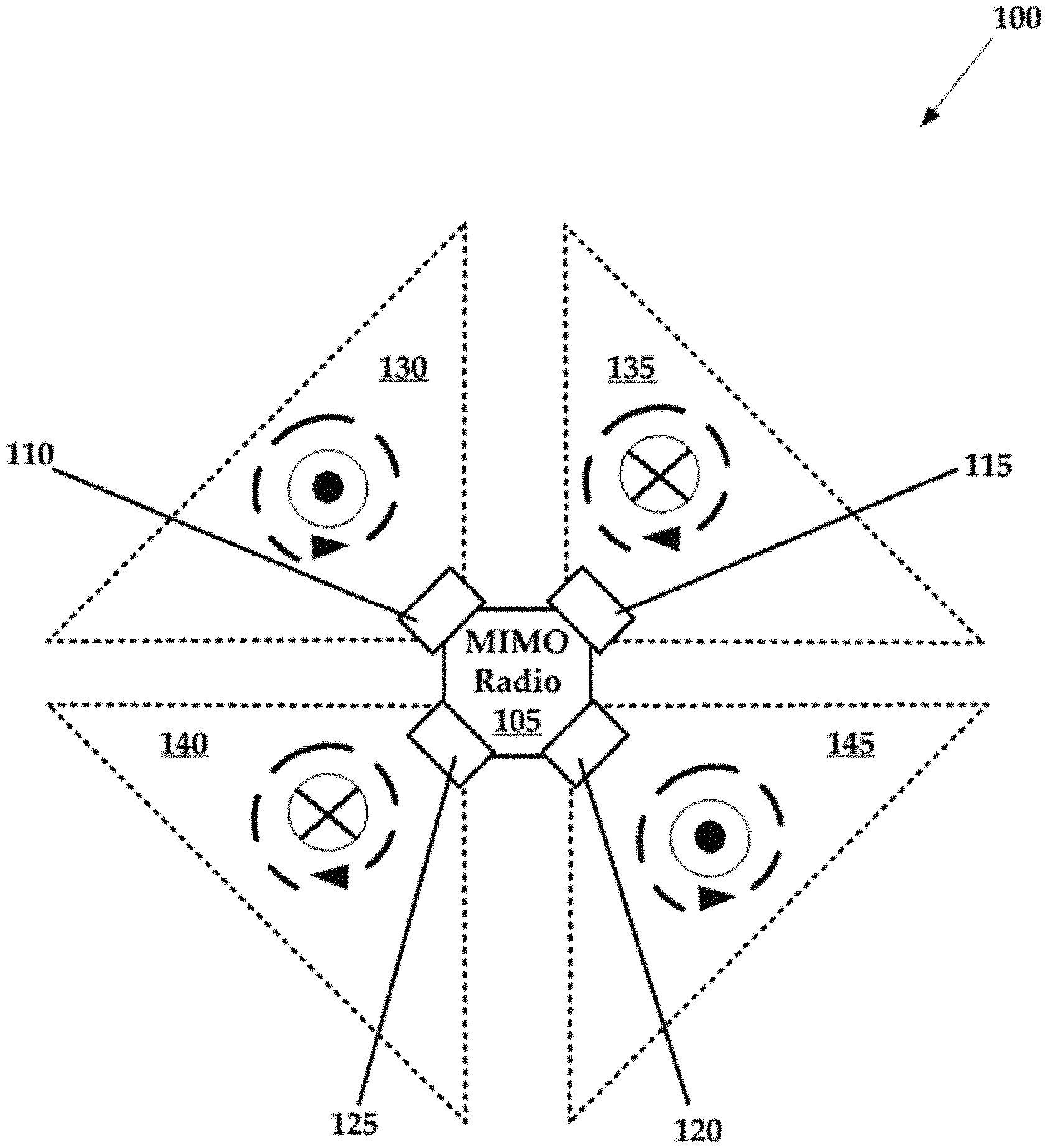
FIG. 1 is a schematic diagram of an exemplary MIMO system that is constructed in accordance with the present technology, having antennas that broadcast in a fixed and non-overlapping manner;
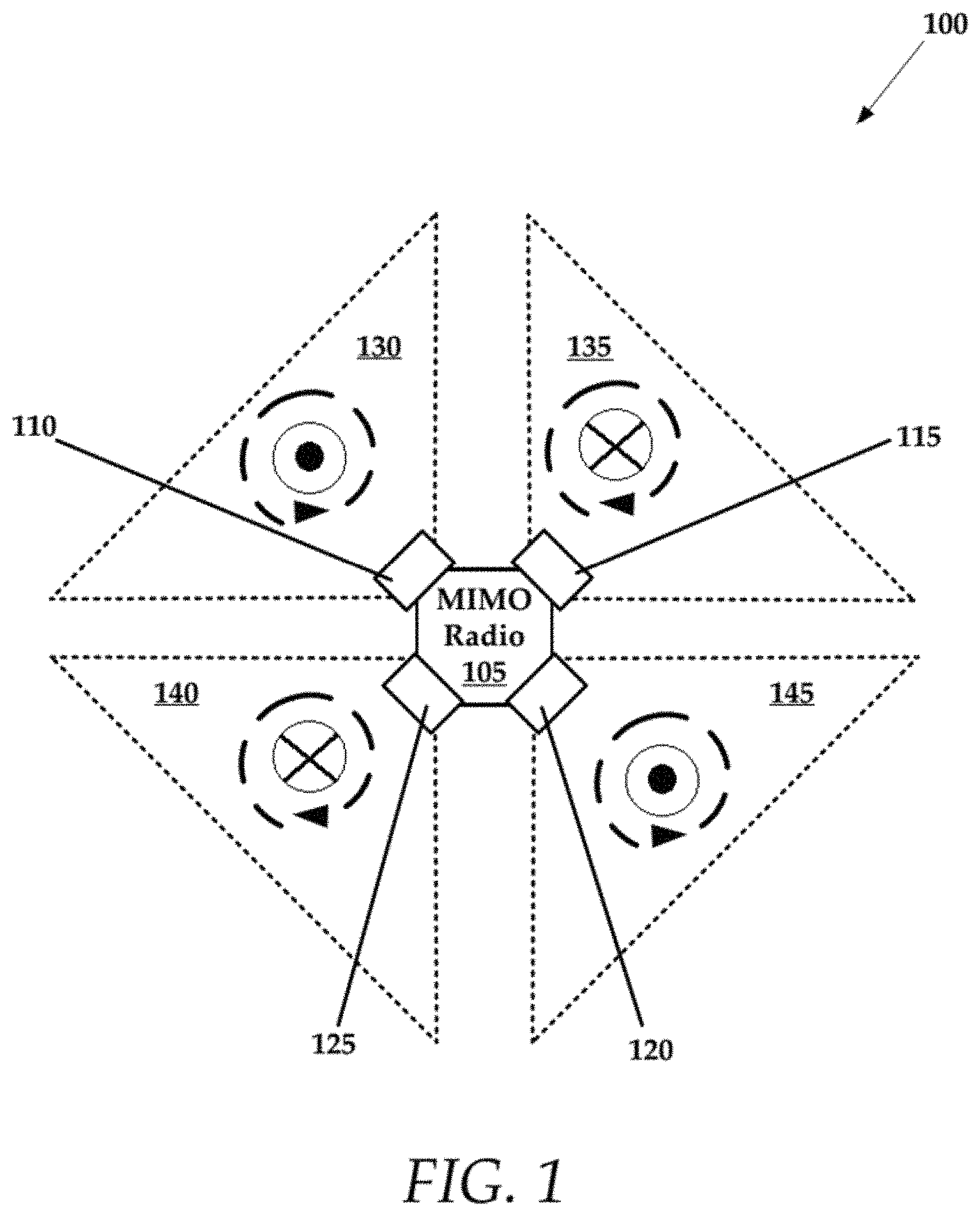
FIG. 2 is a perspective view of a linear array of antennas that can be utilized with an exemplary MIMO system that is constructed in accordance with the present technology;
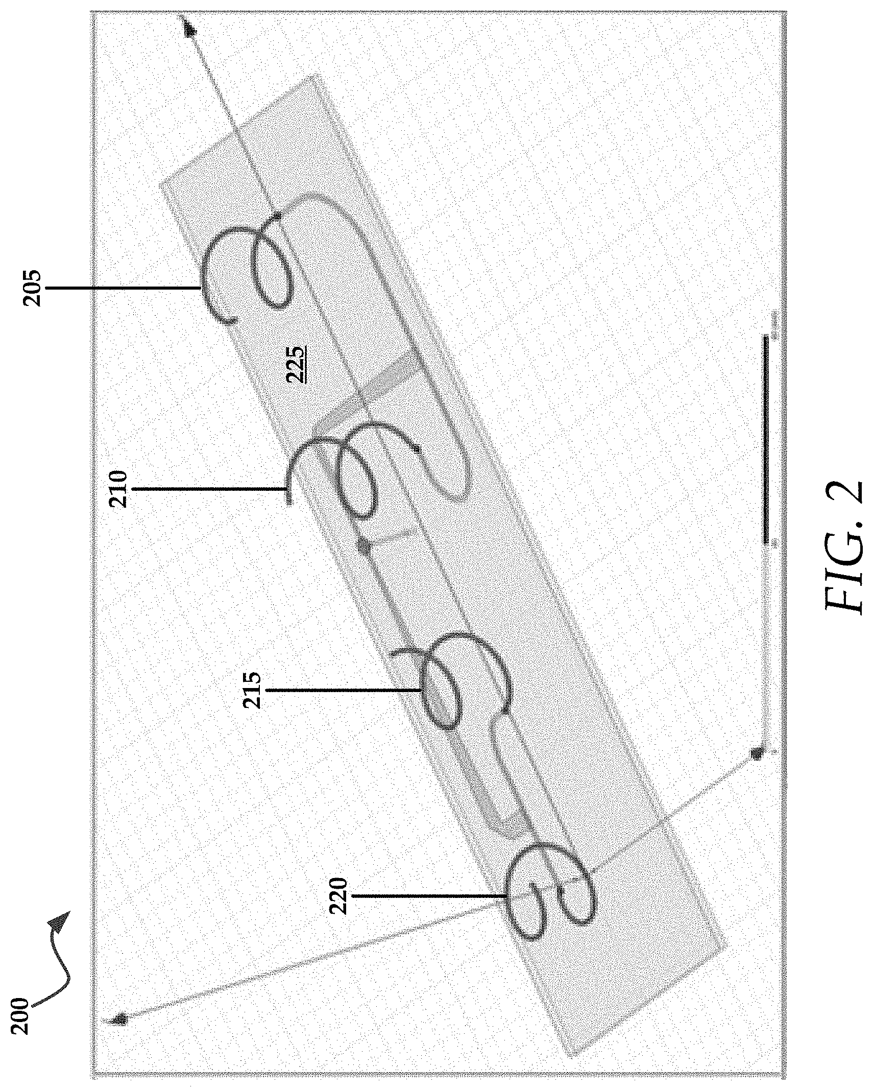
FIG. 3A is a schematic diagram of another exemplary MIMO system that is constructed in accordance with the present technology, having adjacent antennas that have broadcast patterns that at least partially overlap;
FIG. 3B illustrates a broadcast pattern generated by the exemplary MIMO system of FIG. 3A; and
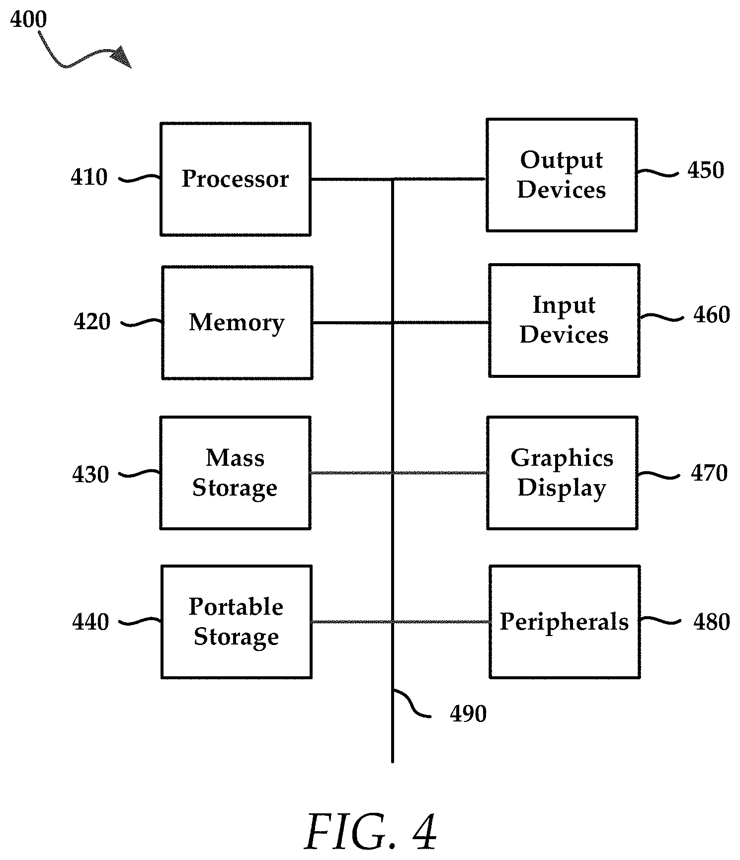
FIG. 4 illustrates an exemplary computing system that is used to implement embodiments according to the present technology.
DESCRIPTION OF EXEMPLARY EMBODIMENTS
While this technology is susceptible of embodiment in many different forms, there is shown in the drawings and will herein be described in detail several specific embodiments with the understanding that the present disclosure is to be considered as an exemplification of the principles of the technology and is not intended to limit the technology to the embodiments illustrated.
The terminology used herein is for the purpose of describing particular embodiments only and is not intended to be limiting of the invention. As used herein, the singular forms "a", "an" and "the" are intended to include the plural forms as well, unless the context clearly indicates otherwise. It will be further understood that the terms "comprises" and/or "comprising," when used in this specification, specify the presence of stated features, integers, steps, operations, elements, and/or components, but do not preclude the presence or addition of one or more other features, integers, steps, operations, elements, components, and/or groups thereof.
It will be understood that like or analogous elements and/or components, referred to herein, is identified throughout the drawings with like reference characters. It will be further understood that several of the figures are merely schematic representations of the present technology. As such, some of the components may have been distorted from their actual scale for pictorial clarity.
In some embodiments, according to the present technology, four arrays of vertically aligned patch antennas provide a 4.times.4 multiple-input multiple-output (MIMO) capable antenna with unique properties. The circular polarization emitted from the antennas ensures that both vertical and horizontal polarizations are energized to the full extent permitted by local regulations. Alternating between right hand circular polarization (RHCP) and left hand circular polarization (LHCP) at 90-degree intervals facilitates 2.times.2 MIMO communication to remote clients provided that the azimuthal response of the arrays adequately overlap one another.
In general, circular polarization occurs when elements of an antenna produce an electromagnetic wave (e.g., generated field) that varies rotationally in a direction of propagation. More specifically, circular polarization is comprised of two orthogonal linear polarized waves which are 90 degrees out of phase.
In one embodiment this system operates as an access point (AP). Four channels are implemented in various configurations in some exemplary embodiments. In one access point embodiment, the four channels are connected to four high gain antennas pointed in four different directions. For example, each antenna is positioned facing outward at a 90 degree angle relative to adjacent antennae. A 360 degree pickup (e.g., coverage area) is achieved in this manner, where each antenna broadcasts in an approximately 90 degree coverage area. For example, first and third antennas are disposed 180 degrees out of phase relative to one another and second and fourth antennas are disposed 180 degrees out of phase relative to one another. Generally, the first, second, third, and fourth isolated sub-sectors each occupy approximately 90 degrees of the 360 degree coverage area.
In another access point embodiment, a linear array of elements is created. The linear array is implemented a series feed or a corporate feed using patches, discs, helical coils, etc. The cardioid pattern of the antennas crushes down the vertical axis, when arranged in a linear array, producing a donut pickup pattern that forms a broadcast/pickup area of approximately 360 degrees. Such a pattern is desirable for an access point, which services wireless devices located at any direction around the AP.
Another embodiment comprises a radio that is coupled to four antennas in order to achieve a 360 degree pickup. Thus, in some embodiments the system includes a four sector antenna with a radio combined. Coupling is performed with Ethernet and Power over Ethernet (POE), and the radio is run at one Gigabit/sec, for example.
For example, FIG. 1 illustrates an exemplary MIMO system 100 that comprises a plurality of circularly polarized antennas 110-125, where antenna broadcasts in a fixed direction over a coverage area.
The plurality of circularly polarized antennas 110-125 are coupled electrically and communicatively to a MIMO radio 105. The MIMO radio 105 controls the transmission and/or receiver scheduling for each of the plurality of circularly polarized antennas 110-125, as well as the data that is transmitted. In some embodiments, antenna 110 broadcasts in area 130, antenna 115 broadcasts in area 135, antenna 120 broadcasts in 145, and antenna 125 broadcasts in area 140.
In general, the MIMO radio 105 is configured to control antenna 110 such that it transmits signals using a first and distinct primary polarization, while antenna 115 transmits signals using a secondary polarization that is orthogonal to the primary polarization. Antenna 120 transmits signals using the primary polarization and antenna 125 transmits signals using the secondary polarization. Advantageously, the adjacent antennae coupled to the MIMO radio 105 alternate in their polarization, using either a primary or secondary polarization.
To be sure, each antenna can be categorized as having some angular orientation (e.g., vertical, horizontal, slant 45.degree., or other angle) as well as polarity of a particular type (e.g., linear, right circular or left circular). The exact orientation of a particular antenna of the present technology can vary anywhere between purely horizontal and purely vertical (and any angle therebetween) as long as the antennas, which are adjacent to this particular antenna, are broadcasting in a manner that is orthogonal thereto.
In a more detailed, but non-limiting example, antenna 110 transmits signals in area 130 in a right handed circular polarization pattern (primary polarization). Antenna 115 transmits signals in area 135 in a left handed circular polarization pattern (secondary and orthogonal polarization). Antenna 120 transmits signals in area 145 in a right handed circular polarization pattern, while antenna 125 transmits signals in area 140 in a right handed circular polarization pattern. It will be understood that polarization, both left handed and right handed occurs both in transmission modes and receive modes for the antennae. This example is merely provided for explaining a non-limiting way of implementing the present technology. Thus while the primary polarization in this example is right handed circularity and the secondary left handed circularity, it will be understood that other permutations can also likewise be utilized. To be sure, the antennas can be configured to broadcast, for example, vertically, horizontally, or in some instances using a slant 45.degree. configuration, such as common 4G LTE systems. Again, the exact orientation of an antenna of the present technology can vary anywhere between purely horizontal and purely vertical (and any angle therebetween) as long as the antennas which are adjacent to this antenna are broadcasting in a manner that is orthogonal thereto.
Other arrangements and configurations of antennae are utilized, although it is advantageous that antennas in a MIMO system can alternate in their polarity with respect to their right-handedness and left-handedness or vertical and horizontal polarity. For example, if an antenna is right handed in its polarization, adjacent antennae, such as antennae that broadcast in adjacent sectors is left handed in their polarization.
Again, each antenna (or a plurality thereof) is vertically polarized or horizontally polarized. The patterns are made tighter (e.g., more directionally focused) in a horizontal direction. However, overlapping the patterns slightly allows for signal pickup from two adjacent sides at locations relatively close to the access point. Such overlapping accomplishes a 2.times.2 MIMO connection if the signals from the adjacent sides are different polarizations relative to one another. An exemplary overlapping configuration to accomplish a 2.times.2 MIMO comprises a vertical-horizontal-vertical-horizontal arrangement of antennae around the 360 configuration.
For example, FIG. 3A illustrates an exemplary MIMO system 300 that comprises a plurality of circularly polarized antennas 310-325, where antenna broadcasts in a fixed direction over a coverage area. The sub-sectors over which adjacent antennas broadcast and/or receive at least partially overlap. For example, overlap 350 shows an area of overlapping broadcast patterns between individual sub-sectors. Antennas 310 and 320 are left handed polarized, while antennas 315 and 325 are right handed polarized.
The plurality of circularly polarized antennas 310-325 are coupled electrically and communicatively to a MIMO radio 305. The MIMO radio 305 controls the transmission and/or receiver scheduling for each of the plurality of circularly polarized antennas 310-325, as well as the data that is transmitted. In some embodiments, antenna 310 broadcasts in area 330, antenna 315 broadcasts in area 335, antenna 320 broadcasts in area 340, and antenna 325 broadcasts in area 345. An area is also referred to as a sub-sector of the entire coverage area for the MIMO system 300.
Antenna 310 broadcast area overlaps the broadcast areas 335 and 340 of adjacent antennas. As mentioned above, this overlap of signal area allows for MIMO signal transmission/receipt. It will be understood that the term "broadcast" as a modifier, is understood to be a "coverage" inasmuch as the antennas both broadcast and receive within a "broadcast area", as controlled by the MIMO radio 305. Thus, a "broadcast area" should be understood as an area that allows for both transmission and receiving of signals, not just transmission or receiving along, although in some embodiments, antennas is dedicated to either transmitting or receiving signals only.
In general, the MIMO radio is configured to control antenna 310 such that it transmits signals using a primary polarization, while antenna 315 transmits signals using a secondary polarization. Antenna 320 transmits signals using the primary polarization and antenna 325 transmits signals using the secondary polarization. Advantageously, the adjacent antennae coupled to the MIMO radio alternate in their polarization, using either a primary or secondary polarization.
In accordance with the present disclosure, antenna 310 transmits signals in area 330 in a left handed circular polarization pattern. Antenna 315 transmits signals in area 335 in a right handed circular polarization pattern. Antenna 320 transmits signals in area 345 in a left handed circular polarization pattern, while antenna 325 transmits signals in area 340 in a right handed circular polarization pattern. It will be understood that polarization, both left handed and right handed occurs both in transmission modes and receive modes for the antennae.
Such a configuration allows radiation in full power extent as permitted by local regulations. For example, under FCC regulations, 47 CFR 15.407 limits the amount of effective isotropic radiated power (EIRP) per polarization orientation for unlicensed radiators. The Unlicensed National Information Infrastructure (U-NII), the upper range (U-NII-3), allows 53 dBm EIRP per polarization in point-to-point applications. In point-to-multipoint applications, U-NII-3 allows 36 dBm EIRP per polarization.
Circular polarization diversity in both transmission and reception, as described above (e.g., RHCP-LHCP-RHCP-LHCP or other similar arrangements), allows for flooding all the polarizations through use of reverse polarization. The flooding provides additional power, for example, 3 dB (or another value) of power. The EIRP appears constant and in some embodiments double the power is achieved.
FIG. 2 illustrates an exemplary array 200 that includes four elements 205-220 that are arranged onto a substrate 225. The elements 205-220 are shown as being clocked at 90 degrees relative to one another, but these elements need not be clocked and only arranged so as to allow for alternating right handed and left handed polarization. While the example provided above contemplates the use of four elements, it will be understood that any number of elements is utilized.
FIG. 3B illustrates a broadcast pattern 355 that is created, for example, by the MIMO system 300 of FIG. 3A. That is, the MIMO radio and its plurality of circularly polarized antennas 310-325 create the broadcast pattern 355. The broadcast pattern 355 of the combined effort of antennas 310-325 is illustrated in contrast with the more irregular broadcast pattern 360 of a single element antenna (not shown).
FIG. 4 illustrates an exemplary computing system 400 (also referenced as system 400) that is used to implement an embodiment of the present technology. The computing system 400 is implemented in, for example, the MIMO radios described above. The computing system 400 of FIG. 4 includes one or more processors 410 and memory 420. Main memory 420 stores, in part, instructions and data for execution by processor 410. Main memory 420 can store the executable code when the system 400 is in operation. The system 400 of FIG. 4 may further include a mass storage device 430, portable storage medium drive(s) 440, output devices 450, user input devices 460, a graphics display 470, and other peripheral devices 480.
The components shown in FIG. 4 are depicted as being connected via a single bus 490. The components are connected through one or more data transport means. Processor unit 410 and main memory 420 is connected via a local microprocessor bus, and the mass storage device 430, peripheral device(s) 480, portable storage device 440, and graphics display 470 is connected via one or more input/output (I/O) buses.
Mass storage device 430, which is implemented with a magnetic disk drive or an optical disk drive, is a non-volatile storage device for storing data and instructions for use by processor unit 410. Mass storage device 430 can store the system software for implementing embodiments of the present technology for purposes of loading that software into main memory 420.
Portable storage device 440 operates in conjunction with a portable non-volatile storage medium, such as a floppy disk, compact disk or digital video disc, to input and output data and code to and from the computing system 400 of FIG. 4. The system software for implementing embodiments of the present technology is stored on such a portable medium and input to the computing system 400 via the portable storage device 440.
Input devices 460 provide a portion of a user interface. Input devices 460 may include an alphanumeric keypad, such as a keyboard, for inputting alphanumeric and other information, or a pointing device, such as a mouse, a trackball, stylus, or cursor direction keys. Additionally, the system 400 as shown in FIG. 4 includes output devices 450. Suitable output devices include speakers, printers, network interfaces, and monitors.
Graphics display 470 may include a liquid crystal display (LCD) or other suitable display device. Graphics display 470 receives textual and graphical information, and processes the information for output to the display device.
Peripherals 480 may include any type of computer support device to add additional functionality to the computing system. Peripheral device(s) 480 may include a modem or a router.
The components contained in the computing system 400 of FIG. 4 are those typically found in computing systems that is suitable for use with embodiments of the present technology and are intended to represent a broad category of such computer components that are well known in the art. Thus, the computing system 400 of FIG. 4 can be a personal computer, hand held computing system, telephone, mobile computing system, workstation, server, minicomputer, mainframe computer, or any other computing system. The computer can also include different bus configurations, networked platforms, multi-processor platforms, etc. Various operating systems can be used including UNIX, Linux, Windows, Macintosh OS, Palm OS, and other suitable operating systems.
Some of the above-described functions are composed of instructions that are stored on storage media (e.g., computer-readable medium). The instructions is retrieved and executed by the processor. Some examples of storage media are memory devices, tapes, disks, and the like. The instructions are operational when executed by the processor to direct the processor to operate in accord with the technology. Those skilled in the art are familiar with instructions, processor(s), and storage media.
It is noteworthy that any hardware platform suitable for performing the processing described herein is suitable for use with the technology. The terms "computer-readable storage medium" and "computer-readable storage media" as used herein refer to any medium or media that participate in providing instructions to a CPU for execution. Such media can take many forms, including, but not limited to, non-volatile media, volatile media and transmission media. Non-volatile media include, for example, optical or magnetic disks, such as a fixed disk. Volatile media include dynamic memory, such as system RAM. Transmission media include coaxial cables, copper wire and fiber optics, among others, including the wires that comprise one embodiment of a bus. Transmission media can also take the form of acoustic or light waves, such as those generated during radio frequency (RF) and infrared (IR) data communications. Common forms of computer-readable media include, for example, a floppy disk, a flexible disk, a hard disk, magnetic tape, any other magnetic medium, a CD-ROM disk, digital video disk (DVD), any other optical medium, any other physical medium with patterns of marks or holes, a RAM, a PROM, an EPROM, an EEPROM, a FLASHEPROM, any other memory chip or data exchange adapter, a carrier wave, or any other medium from which a computer can read.
Various forms of computer-readable media are involved in carrying one or more sequences of one or more instructions to a CPU for execution. A bus carries the data to system RAM, from which a CPU retrieves and executes the instructions. The instructions received by system RAM can optionally be stored on a fixed disk either before or after execution by a CPU.
Computer program code for carrying out operations for aspects of the present invention is written in any combination of one or more programming languages, including an object oriented programming language such as Java, Smalltalk, C++ or the like and conventional procedural programming languages, such as the "C" programming language or similar programming languages. The program code may execute entirely on the user's computer, partly on the user's computer, as a stand-alone software package, partly on the user's computer and partly on a remote computer or entirely on the remote computer or server. In the latter scenario, the remote computer is connected to the user's computer through any type of network, including a local area network (LAN) or a wide area network (WAN), or the connection is made to an external computer (for example, through the Internet using an Internet Service Provider).
The corresponding structures, materials, acts, and equivalents of all means or step plus function elements in the claims below are intended to include any structure, material, or act for performing the function in combination with other claimed elements as specifically claimed. The description of the present invention has been presented for purposes of illustration and description, but is not intended to be exhaustive or limited to the invention in the form disclosed. Many modifications and variations will be apparent to those of ordinary skill in the art without departing from the scope and spirit of the invention. Exemplary embodiments were chosen and described in order to best explain the principles of the present technology and its practical application, and to enable others of ordinary skill in the art to understand the invention for various embodiments with various modifications as are suited to the particular use contemplated.
Aspects of the present invention are described above with reference to flowchart illustrations and/or block diagrams of methods, apparatus (systems) and computer program products according to embodiments of the invention. It will be understood that each block of the flowchart illustrations and/or block diagrams, and combinations of blocks in the flowchart illustrations and/or block diagrams, can be implemented by computer program instructions. These computer program instructions is provided to a processor of a general purpose computer, special purpose computer, or other programmable data processing apparatus to produce a machine, such that the instructions, which execute via the processor of the computer or other programmable data processing apparatus, create means for implementing the functions/acts specified in the flowchart and/or block diagram block or blocks.
These computer program instructions may also be stored in a computer readable medium that can direct a computer, other programmable data processing apparatus, or other devices to function in a particular manner, such that the instructions stored in the computer readable medium produce an article of manufacture including instructions which implement the function/act specified in the flowchart and/or block diagram block or blocks.
The computer program instructions may also be loaded onto a computer, other programmable data processing apparatus, or other devices to cause a series of operational steps to be performed on the computer, other programmable apparatus or other devices to produce a computer implemented process such that the instructions which execute on the computer or other programmable apparatus provide processes for implementing the functions/acts specified in the flowchart and/or block diagram block or blocks.
The flowchart and block diagrams in the figures illustrate the architecture, functionality, and operation of possible implementations of systems, methods and computer program products according to various embodiments of the present invention. In this regard, each block in the flowchart or block diagrams may represent a module, segment, or portion of code, which comprises one or more executable instructions for implementing the specified logical function(s). It should also be noted that, in some alternative implementations, the functions noted in the block may occur out of the order noted in the figures. For example, two blocks shown in succession may, in fact, be executed substantially concurrently, or the blocks may sometimes be executed in the reverse order, depending upon the functionality involved. It will also be noted that each block of the block diagrams and/or flowchart illustration, and combinations of blocks in the block diagrams and/or flowchart illustration, can be implemented by special purpose hardware-based systems that perform the specified functions or acts, or combinations of special purpose hardware and computer instructions.
While various embodiments have been described above, it should be understood that they have been presented by way of example only, and not limitation. The descriptions are not intended to limit the scope of the technology to the particular forms set forth herein. Thus, the breadth and scope of a preferred embodiment should not be limited by any of the above-described exemplary embodiments. It should be understood that the above description is illustrative and not restrictive. To the contrary, the present descriptions are intended to cover such alternatives, modifications, and equivalents as is included within the spirit and scope of the technology as defined by the appended claims and otherwise appreciated by one of ordinary skill in the art. The scope of the technology should, therefore, be determined not with reference to the above description, but instead should be determined with reference to the appended claims along with their full scope of equivalents.
* * * * *
References
D00000
D00001
D00002
D00003
D00004
D00005
XML
uspto.report is an independent third-party trademark research tool that is not affiliated, endorsed, or sponsored by the United States Patent and Trademark Office (USPTO) or any other governmental organization. The information provided by uspto.report is based on publicly available data at the time of writing and is intended for informational purposes only.
While we strive to provide accurate and up-to-date information, we do not guarantee the accuracy, completeness, reliability, or suitability of the information displayed on this site. The use of this site is at your own risk. Any reliance you place on such information is therefore strictly at your own risk.
All official trademark data, including owner information, should be verified by visiting the official USPTO website at www.uspto.gov. This site is not intended to replace professional legal advice and should not be used as a substitute for consulting with a legal professional who is knowledgeable about trademark law.