Acoustic transmission device and process for tracking selected hosts
Deng , et al. A
U.S. patent number 10,739,434 [Application Number 16/143,273] was granted by the patent office on 2020-08-11 for acoustic transmission device and process for tracking selected hosts. This patent grant is currently assigned to Battelle Memorial Institute. The grantee listed for this patent is Battelle Memorial Institute. Invention is credited to Richard S. Brown, Samuel S. Cartmell, Zhiqun Deng, Huidong Li, Jun Lu, Jayson J. Martinez, Mitchell J. Myjak, Jie Xiao.


| United States Patent | 10,739,434 |
| Deng , et al. | August 11, 2020 |
Acoustic transmission device and process for tracking selected hosts
Abstract
A new acoustic tag and process are disclosed for identifying and tracking underwater hosts in up to three dimensions. The acoustic tag has an operation lifetime up to a year or longer at a pulse rate interval of about 15 seconds. The acoustic tag has a signal detection range up to at least about 500 meters that enhances detection probability.
| Inventors: | Deng; Zhiqun (Richland, WA), Li; Huidong (Richland, WA), Lu; Jun (Richland, WA), Myjak; Mitchell J. (Richland, WA), Martinez; Jayson J. (Richland, WA), Xiao; Jie (Richland, WA), Brown; Richard S. (Richland, WA), Cartmell; Samuel S. (Richland, WA) | ||||||||||
|---|---|---|---|---|---|---|---|---|---|---|---|
| Applicant: |
|
||||||||||
| Assignee: | Battelle Memorial Institute
(Richland, WA) |
||||||||||
| Family ID: | 55024218 | ||||||||||
| Appl. No.: | 16/143,273 | ||||||||||
| Filed: | September 26, 2018 |
Prior Publication Data
| Document Identifier | Publication Date | |
|---|---|---|
| US 20190018100 A1 | Jan 17, 2019 | |
Related U.S. Patent Documents
| Application Number | Filing Date | Patent Number | Issue Date | ||
|---|---|---|---|---|---|
| 14631587 | Feb 25, 2015 | 10101429 | |||
| Current U.S. Class: | 1/1 |
| Current CPC Class: | A61B 5/1112 (20130101); A01K 11/006 (20130101); A01K 61/90 (20170101); A61B 5/0015 (20130101); G06K 17/00 (20130101); G01S 1/72 (20130101); A61B 5/07 (20130101); G01S 5/18 (20130101); H04B 1/034 (20130101); A61B 2503/40 (20130101); G06K 19/0728 (20130101); A61B 2562/08 (20130101) |
| Current International Class: | G01S 1/72 (20060101); H04B 1/034 (20060101); A01K 11/00 (20060101); A61B 5/00 (20060101); A61B 5/11 (20060101); A61B 5/07 (20060101); G06K 17/00 (20060101); A01K 61/90 (20170101); G01S 5/18 (20060101); G06K 19/07 (20060101) |
References Cited [Referenced By]
U.S. Patent Documents
| 2775939 | January 1957 | Fogal |
| 3100866 | August 1963 | Marks |
| 3100886 | August 1963 | Marks |
| 3262093 | July 1966 | Junger |
| 3292303 | December 1966 | Fors |
| 3311830 | March 1967 | Skirvin |
| 3576732 | April 1971 | Weidinger et al. |
| 3713086 | January 1973 | Trott |
| 4042845 | August 1977 | Hackett |
| 4241535 | December 1980 | Tsukuda |
| 4259415 | March 1981 | Tamura et al. |
| 4336709 | June 1982 | Meek |
| 4353004 | October 1982 | Kleinschmidt |
| 4392236 | July 1983 | Sandstrom et al. |
| 4679559 | July 1987 | Jefferts |
| 4762427 | August 1988 | Hori et al. |
| 4790090 | December 1988 | Sharber |
| 4970988 | November 1990 | Heisey |
| 4986276 | January 1991 | Wright |
| 5177891 | January 1993 | Holt |
| 5211129 | May 1993 | Taylor et al. |
| 5324940 | June 1994 | Ekstrom |
| 5344357 | September 1994 | Lyczek |
| 5517465 | May 1996 | Nestler et al. |
| 5675555 | October 1997 | Evans et al. |
| 5697384 | December 1997 | Miyawaki et al. |
| 5857881 | January 1999 | Zippel, Sr. |
| 5974304 | October 1999 | Chen |
| 5995451 | November 1999 | Evans et al. |
| 6021731 | February 2000 | French et al. |
| 6201766 | March 2001 | Carlson et al. |
| 6662742 | December 2003 | Shelton et al. |
| 6712772 | March 2004 | Cohen et al. |
| 6928765 | August 2005 | Brickett |
| 7016260 | March 2006 | Baray |
| 7289931 | October 2007 | Ebert |
| 7457720 | November 2008 | Ebert |
| 8032429 | October 2011 | Shafer |
| 8033890 | October 2011 | Warner et al. |
| 8360327 | January 2013 | Clarke |
| 8448592 | May 2013 | Crowell et al. |
| 8564985 | October 2013 | van Straaten |
| 9266591 | February 2016 | Lu |
| 10033469 | July 2018 | Deng et al. |
| 10033470 | July 2018 | Deng et al. |
| 10067112 | September 2018 | Deng et al. |
| 10101429 | October 2018 | Deng |
| 2003/0117893 | June 2003 | Baray |
| 2003/0128847 | July 2003 | Smith |
| 2004/0133081 | July 2004 | Teller et al. |
| 2006/0218374 | September 2006 | Ebert |
| 2007/0083119 | April 2007 | Adachi |
| 2007/0088194 | April 2007 | Tahar et al. |
| 2007/0103314 | May 2007 | Geissler |
| 2007/0288160 | December 2007 | Ebert |
| 2008/0269614 | October 2008 | Adachi |
| 2009/0073802 | March 2009 | Nizzola et al. |
| 2009/0079368 | March 2009 | Poppen |
| 2009/0188320 | July 2009 | Greenough |
| 2011/0105829 | May 2011 | Ball |
| 2011/0163857 | July 2011 | August et al. |
| 2011/0181399 | July 2011 | Pollack et al. |
| 2011/0254529 | October 2011 | van Straaten |
| 2012/0134239 | May 2012 | Struthers |
| 2012/0277550 | November 2012 | Rosenkranz et al. |
| 2013/0012865 | January 2013 | Sallberg et al. |
| 2013/0181839 | July 2013 | Cao |
| 2013/0324059 | December 2013 | Lee et al. |
| 2014/0211594 | July 2014 | Allen et al. |
| 2015/0063072 | March 2015 | Deng et al. |
| 2015/0241566 | August 2015 | Chakraborty et al. |
| 2015/0289479 | October 2015 | Allen et al. |
| 2016/0211924 | July 2016 | Deng et al. |
| 2016/0245894 | August 2016 | Deng et al. |
| 2017/0089878 | March 2017 | Deng et al. |
| 2017/0164581 | June 2017 | Deng et al. |
| 2017/0170850 | June 2017 | Deng et al. |
| 2018/0055007 | March 2018 | Deng et al. |
| 2091043 | Sep 1994 | CA | |||
| 1424592 | Jun 2003 | CN | |||
| 102568463 | Jul 2012 | CN | |||
| 102598716 | Jul 2012 | CN | |||
| 202414143 | Sep 2012 | CN | |||
| 102754249 | Oct 2012 | CN | |||
| 2014800479315 | Jul 2017 | CN | |||
| 2037396 | Mar 2009 | EP | |||
| 1705500 | Jun 2010 | EP | |||
| 1195633 | Jun 1970 | GB | |||
| 2188028 | Sep 1987 | GB | |||
| 61-291294 | Dec 1986 | JP | |||
| WO 95/03691 | Feb 1995 | WO | |||
| WO 2011/068825 | Jun 2011 | WO | |||
| WO 2011/079338 | Jul 2011 | WO | |||
| PCT/US2014/05357 | Dec 2014 | WO | |||
| PCT/US2014/053578 | Mar 2015 | WO | |||
| WO 2015/031853 | Mar 2015 | WO | |||
| PCT/US2015/062200 | Feb 2016 | WO | |||
| PCT/US2014/053578 | Mar 2016 | WO | |||
| PCT/US2016/054981 | Nov 2016 | WO | |||
| PCT/US2016/055045 | Feb 2017 | WO | |||
| PCT/US2015/062200 | Aug 2017 | WO | |||
| PCT/US2017/038082 | Sep 2017 | WO | |||
| PCT/US2017/038082 | Nov 2017 | WO | |||
| PCT/US2016/054981 | Jun 2018 | WO | |||
| PCT/US2016/055045 | Jun 2018 | WO | |||
Other References
|
Deng et al., U.S. Appl. No. 16/193,968, filed Nov. 16, 2018, titled "Methods for Attaching Transmitters to Animals", 51 pages. cited by applicant . Aktakka et al., "Energy Scavenging from Insect Flight", Journal of Micromechanics and Microengineering vol. 21, 095016, 2011, United Kingdom, 10 pages. cited by applicant . Brown et al., "An Evaluation of the Maximum Tag Burden for Implantation of Acoustic Transmitters in Juvenile Chinook Salmon", North American Journal of Fisheries Management vol. 30, 2010, United States, pp. 499-505. cited by applicant . Cha et al., "Energy Harvesting from a Piezoelectric Biomimetic Fish Tail", Renewable Energy vol. 86, 2016, Netherlands, pp. 449-458. cited by applicant . Cha et al., "Energy Harvesting from the Tail Beating of a Carangiform Swimmer using Ionic Polymer-Metal Composites", Bioinspiration and Biomimetics vol. 8, 2013, United Kingdom, 15 pages. cited by applicant . Cook et al., "A Comparison of Implantation Methods for Large PIT Tags or Injectable Acoustic Transmitters in Juvenile Chinook Salmon", Fisheries Research vol. 154, 2014, Netherlands, pp. 213-223. cited by applicant . Dagdeviren et al., "Conformal Piezoelectric Energy Harvesting and Storage from Motions of the Heart, Lung, and Diaphragm", Proceedings of the National Academy of Sciences of the United States of America vol. 111, 2014, United States, pp. 1927-1932. cited by applicant . Deng et al., "A Cabled Acoustic Telemetry System for Detecting and Tracking Juvenile Salmon: Part 2. Three-Dimensional Tracking and Passage Outcomes", Sensors vol. 11, 2011, Switzerland, pp. 5661-5676, cited by applicant . Deng et al., "An Injectable Acoustic Transmitter for Juvenile Salmon", Scientific Reports, Jan. 29, 2015, United Kingdom, 6 pages. cited by applicant . Deng et al., "Design and Instrumentation of a Measurement and Calibration System for an Acoustic Telemetry System", Sensors vol. 10, 2010, Switzerland, pp. 3090-3099. cited by applicant . Deng et al., U.S. Appl. No. 62/267,738, filed Dec. 15 2015, titled "Transmitters for Animals and Methods for Transmitting from Animals", 42 pages. cited by applicant . Deng et al., U.S. Appl. No. 62/267,797, filed Dec. 15, 2015, titled "Signal Transmitter and Methods for Transmitting Signals from Animals", 34 pages. cited by applicant . Eppard, "Juvenile Salmon Acoustic Telemetry System JSATS", Dec. 14, 2011, URL: http://www.nwcouncil.org/media/23478/jsats.pdf, pp. 1-13. cited by applicant . Erturk et al., "Underwater Thrust and Power Generation Using Flexible Piezoelectric Composites: An Experimental Investigation Toward Self-Powered Swimmer-Sensor Platforms", Smart Materials and Structures vol. 20, 125013, 2011, United Kingdom, 11 pages. cited by applicant . Hwang et al., "Powered Cardiac Pacemaker Enabled by Flexible Single Crystalline PMN-PT Piezoelectric Energy Harvester", Advanced Materials vol. 26, 2014, Germany, pp. 4880-4887. cited by applicant . Hwang et al., "Self-Powered Deep Brain Stimulation via a Flexible PIMNT Energy Harvester", Energy and Environmental Science vol. 8, 2015, United Kingdom, pp. 2677-2684. cited by applicant . Lam et al., "Physical Characteristics and Rate Performance of (CFx)n (0.33>x>9,66) in Lithium Batteries", Journal of Power Sources vol. 153, 2006, Netherlands, pp. 354-359. cited by applicant . Li et al., "Design Parameters of a Miniaturized Piezoelectric Underwater Acoustic Transmitter", Sensors vol. 12, 2012, Switzerland, pp. 9098-9109. cited by applicant . Li et al., "Energy Harvesting from Low Frequency Applications using Piezoelectric Materials", Applied Physics Reviews 1, 041301, 2014, United States, 20 pages. cited by applicant . Li et al., "Piezoelectric Materials Used in Underwater Acoustic Transducers" Sensor Letters vol. 10 (3/4), 2012, United States, pp. 679-697. cited by applicant . Li et al., "Piezoelectric Transducer Design for a Miniaturized Injectable Acoustic Transmitter", Smart Materials and Structures vol. 24, 115010, 2015, United Kingdom, 9 pages. cited by applicant . McMichael et al., "The Juvenile Salmon Acoustic Telemetry System: A New Tool", Fisheries vol. 35, No. 1, Jan. 1, 2010, United States, pp. 9-22. cited by applicant . Meduri et al., "Hybrid CVx-Ag2V4011 as a High-Energy, Power Density Cathode for Application in an Underwater Acoustic Microtransmitter", Electrochemistry Communications vol. 13, 2011, United States, pp. 1344-1348. cited by applicant . Ritchie et al., "Further Developments of Lithium/Polycarbon Monofluoride Envelope Cells", Journal of Power Sources vol. 96, 2001, Netherlands, pp. 180-183. cited by applicant . Rub et al., "Comparative Performance of Acoustic-Tagged and Passive Integrated Transponder-Tagged Juvenile Salmonids in the Columbia and Snake Rivers", U.S. Army Corps of Engineers, Portland District, Portland Oregon, 2007, United States, 163 pages. cited by applicant . S.M. Corporation, "Macro Fiber Composite--MFC" Smart Material Brochure, United States, 8 pages. cited by applicant . Shafer, "Energy Harvesting and Wildlife Monitoring", available online at http://www.ofwim.org/wp-content/uploads/2014/11/ Shafer_keynote.pdf, 2014, 36 pages. cited by applicant . Weiland et al., "A Cabled Acoustic Telemetry System for Detecting and Tracking Juvenile Salmon: Part 1. Engineering Design and Instrumentation", Sensors vol. 11, No. 12, Dec. 26, 2011, Switzerland, pp. 5645-5660. cited by applicant . Yazami et al., "Fluorinated Carbon Nanofibres for High Energy and High Power Densities Primary Lithium Batteries", Electrochemistry Communications vol. 9, 2007, Netherlands, pp. 1850-1855. cited by applicant . Zhang et al., "Enhancement of Discharge Performance of Li/CFx Cell by Thermal Treatment of CFx Cathode Material", Journal of Power Sources vol. 188, 2009, Netherlands, pp. 601-605. cited by applicant . Adams et al., "Effects of Surgically and Gastrically Implanted Radio Transmitters on Swimming Performance and Predator Avoidance of Juvenile Chinook Salmon (Oncorhynchus tshawytscha)", Canadian Journal of Fisheries and Aquatic Sciences 55, 1998, Canada, pp. 781-787. cited by applicant . Angela et al., "Effects of Acoustic Transmitters on Swimming Performance and Predator Avoidance of Juvenile Chinook Salmon", North American Journal of Fisheries Management 24, 2004, United States, pp. 162-170. cited by applicant . Atlantic States Marine Fisheries Commission, "American Eel Benchmark Stock Assessment Report No. 12-01", May 2012, United States, 340 pages. cited by applicant . Bams, "Differences in Performance of Naturally and Artificially Propagated Sockeye Salmon Migrant Fry, as Measured with Swimming and Predation Tests", Journal of the Fisheries Board of Canada 24(5), 1967, Canada, pp. 1117-1153. cited by applicant . Barbin et al., "Behaviour and Swimming Performance of Elvers of the American Eel, Anguilla Rostrata, in an Experimental Flume", Journal of Fish Biology 45, 1994, United Kingdom, pp. 111-121. cited by applicant . Biopack Systems, Inc. Hardware Guide, 2013, 152 pages. cited by applicant . Boubee et al., "Downstream Passage of Silver Eels at a Small Hydoelectric Facility", Fisheries Management and Ecology vol. 13, 2006, United Kingdom, pp. 165-176. cited by applicant . Brett, "The Respiratory Metabolism and Swimming Performance of Young Sockeye Salmon", Journal of the Fisheries Board of Canada 21(5), 1964, Canada, pp. 1183-1226. cited by applicant . Brown et al., "Evidence to Challenge the "2% Rule" for Biotelemetry", North American Journal of Fisheries Management 19, 1999, United States, pp. 867-871. cited by applicant . Brown et al., "Survival of Seaward-Migrating PIT and Acoustic-Tagged Juvenile Chinook Salmon in the Snake and Columbia Rivers: An Evaluation of Length-Specific Tagging Effects", Animal Biotelemetry 1:8, 2013, United States, 13 pages. cited by applicant . Brown, "Design Considerations for Piezoelectric Polymer Ultrasound Transducers", IEEE Transactions on Ultrasonics, Ferroelectrics, and Frequency Control vol. 47, No. 6, Nov. 2000, United States, pp. 1377-1396. cited by applicant. |
Primary Examiner: Baghdasaryan; Hovhannes
Assistant Examiner: Ndure; Amie M
Attorney, Agent or Firm: Wells St. John P.S.
Government Interests
STATEMENT REGARDING RIGHTS TO INVENTION MADE UNDER FEDERALLY-SPONSORED RESEARCH AND DEVELOPMENT
This invention was made with Government support under Contract DE-AC05-76RL01830 awarded by the U.S. Department of Energy. The Government has certain rights in the invention.
Parent Case Text
RELATED PATENT DATA
This application is a continuation of and claims priority to U.S. patent application Ser. No. 14/631,587, which was filed Feb. 25, 2015, the teachings of which are incorporated herein by reference.
Claims
What is claimed is:
1. An acoustic transmission (tag) device, comprising: a power source; a tag circuit; a piezoelectric transducer; a housing configured to be associated with a host to be tracked and wherein the housing is coupled with the power source, the tag circuit and the piezoelectric transducer; wherein the power source delivers a power source voltage to power the tag circuit; wherein the tag circuit comprises: a dual boost converter sub-circuit coupled with the power source and configured to receive the power source voltage; and a plurality of switches individually coupled with the dual boost converter sub-circuit and the piezoelectric transducer, wherein each of the switches is configured to selectively apply electrical energy received from the dual boost converter sub-circuit to the piezoelectric transducer; and wherein the switches are coupled with different terminals of the piezoelectric transducer.
2. The acoustic device of claim 1, further comprising an inductor coupled with one of the switches and one of the terminals of the piezoelectric transducer.
3. The acoustic device of claim 1, wherein the dual boost converter sub-circuit generates voltage potentials that alternate between about -3 volts and about +7 volts.
4. The acoustic device of claim 1, wherein the tag circuit delivers a selected voltage to the piezoelectric transducer that is at least about 20 volts (peak-to-peak).
5. The acoustic device of claim 1, wherein the dual boost converter sub-circuit comprises a plurality of output terminals coupled with the switches, and wherein the dual boost converter sub-circuit is configured to output different voltages via the output terminals.
6. The acoustic device of claim 5, wherein the different voltages have different electrical polarities.
7. The acoustic device of claim 5, wherein one of the voltages outputted via one of the output terminals is greater than the power source voltage and another of the voltages outputted via another of the output terminals is less than the power source voltage.
8. The acoustic device of claim 1, wherein the tag has a volume of about 429 mm.sup.3 or less.
9. The acoustic device of claim 1, wherein the tag has a mass of about 720 mg or less in air.
10. The acoustic device of claim 1, wherein the housing is configured to be received within the host to be tracked.
11. A method for tracking a selected host, comprising: associating an acoustic transmission (tag) device with a selected host to be tracked; while the acoustic transmission (tag) device is associated with the host, delivering electrical energy from a tag circuit to a piezoelectric transducer in the acoustic transmission (tag) device to generate an acoustic transmission signal; wherein the delivering comprises delivering using a plurality of switches individually configured to selectively deliver the electrical energy from a dual boost converter sub-circuit to the piezoelectric transducer; while the acoustic transmission (tag) device is associated with the host, transmitting the acoustic transmission signal from the piezoelectric transducer externally of the host; and wherein the delivering comprises delivering at least some of the electrical energy using an inductor coupled with one of the switches and the piezoelectric transducer.
12. The method of claim 11, wherein the switches are coupled with different terminals of the piezoelectric transducer.
13. The method of claim 11, wherein the delivering the electrical energy includes generating voltage potentials in the dual boost converter sub-circuit that alternate between about -3 volts and about +7 volts.
14. The method of claim 11, wherein the delivering the electrical energy includes delivering a voltage of at least about 20 volts (peak-to-peak).
15. The method of claim 11, wherein the delivering the electrical energy comprises outputting a plurality of voltages via a plurality of output terminals of the dual boost converter sub-circuit.
16. The method of claim 15, wherein the voltages have different electrical polarities.
17. The method of claim 15, further comprising supplying a power source voltage from a power source to the tag circuit, and wherein one of the voltages outputted via one of the output terminals is greater than the power source voltage and another of the voltages outputted via another of the output terminals is lower than the power source voltage.
18. The method of claim 11, wherein the tag has a volume of about 429 mm.sup.3 or less.
19. The method of claim 11, wherein the tag has a mass of about 720 mg or less in air.
20. The method of claim 11, wherein the associating comprises providing the tag within the host to be tracked.
21. An acoustic transmission (tag) device, comprising: a power source; a tag circuit; a piezoelectric transducer; a housing configured to be associated with a host to be tracked and wherein the housing is coupled with the power source, the tag circuit and the piezoelectric transducer; wherein the power source delivers a power source voltage to power the tag circuit; and wherein the tag circuit comprises: a dual boost converter sub-circuit coupled with the power source and configured to receive the power source voltage; a plurality of switches individually coupled with the dual boost converter sub-circuit and the piezoelectric transducer, wherein each of the switches is configured to selectively apply electrical energy received from the dual boost converter sub-circuit to the piezoelectric transducer; and an inductor coupled with one of the switches and a terminal of the piezoelectric transducer.
22. A method for tracking a selected host, comprising: associating an acoustic transmission (tag) device with a selected host to be tracked; while the acoustic transmission (tag) device is associated with the host, delivering electrical energy from a tag circuit to a piezoelectric transducer in the acoustic transmission (tag) device to generate an acoustic transmission signal; wherein the delivering comprises delivering using a plurality of switches individually configured to selectively deliver the electrical energy from a dual boost converter sub-circuit to the piezoelectric transducer; while the acoustic transmission (tag) device is associated with the host, transmitting the acoustic transmission signal from the piezoelectric transducer externally of the host; and wherein the switches are coupled with different terminals of the piezoelectric transducer.
Description
FIELD OF THE INVENTION
The present invention relates generally to acoustic tracking devices and systems. More particularly, the present invention relates to attachable acoustic transmission devices for detection and remote tracking of smaller hosts both inanimate and animate in up to three dimensions in real-time or as a function of time.
BACKGROUND OF THE INVENTION
Acoustic telemetry involves acoustic devices (or tags) commonly used to monitor behavior of fish. Acoustic tags transmit a sound signal that transmits identification, location, and other information about a tagged fish to a receiver at a selected pulse rate interval (PRI), or "ping" rate. The receiver detects signals emitted by the acoustic tag and converts the sound signals into digital data. Post-processing software then processes the digital data and provides location information about the tag and thus the behavior of the fish when the receiver detects the sound signal. By identifying the signature of the acoustic signal a specific animal may be identified, which allows tracking the behavior of the host. Acoustic data may be used, e.g., to estimate survival of fish through dams and other routes of passage. However, conventional transmitters are too large for small hosts (30-100 g mass and 180-270 mm length), have short lifetimes, and/or have an inadequate transmission range that to date have precluded intensive research of small hosts such as juvenile sturgeon using acoustic telemetry techniques. Recently, an injectable acoustic tag was developed for the U.S. Army Corps of Engineers for tracking juvenile salmon detailed in U.S. patent application Ser. No. 14/014,035 filed 29 Aug. 2013, and other acoustic tags for tracking other small hosts detailed in Patent Application No.: PCT/US14/53578 filed 29 Aug. 2014, which references are incorporated herein in their entirety. The injectable acoustic tag works well for tracking yearling Chinook salmon in river systems. However, it is not optimal for long-term monitoring of hosts requiring a stronger acoustic signal and longer service life including, e.g., juvenile (<1 year old) sturgeon. Accordingly, new tag designs are needed that reduce the overall size, mass, and/or volume, that enhance the power source voltage, tag lifetimes, and transmission range, and reduce adverse effects and costs associated with attachment (which includes implantation) thus broadening the range of potential applications including, e.g., investigating behavior and habitat of juvenile sturgeon and other small species. The present invention addresses these needs.
SUMMARY OF THE INVENTION
The present invention includes a new acoustic transmission device (acoustic tag) and a process for remotely tracking various hosts in up to three dimensions in real-time or as a function of time. The acoustic tag may include a power source that delivers a power source voltage to power a tag circuit. The tag circuit may deliver a selected voltage to a piezoelectric transducer (PZT) that transmits an acoustic transmission signal at a signal intensity selected between about 159 dB and about 163 dB. The tag may be configured to provide a selectable tag lifetime at the selected signal intensity of at least about 98 days at a pulse rate interval of about 5 seconds.
The present invention also includes a method for tracking selected hosts. The method may include delivering a selected voltage from a tag circuit powered by a power source to PZT in the acoustic transmission (tag) device. The tag device may be attached to the selected host. The tag circuit may generate an acoustic transmission signal in the PZT at a selected signal intensity over a selectable tag lifetime. Signal intensity may be selected between about 159 dB and about 163 dB.
In some embodiments, the tag lifetime may be at least about 365 days at a transmission (ping) rate of about 15 seconds at a signal intensity of 161 dB.
In some embodiments, the tag lifetime may be at least about 249 days at a transmission (ping) rate of 10 seconds at a signal intensity of 161 dB.
In some embodiments, the tag lifetime may be about 156 days at a pulse rate interval of about 5 seconds and an acoustic signal intensity of 159 dB.
In some embodiments, the acoustic tag may include a power source that delivers a selectable power source voltage that powers components of the acoustic tag located on, or coupled to, a tag circuit. In various embodiments, the power source voltage may be selected between about 1.8 V and about 3.0 V.
In some embodiments, the tag circuit may include a dual boost converter sub-circuit that couples to two analog switches. In some embodiments, one of the analog switches may be coupled to the PZT through an inductor. The other analog switch may be coupled directly to the PZT. This configuration allows a higher peak-to-peak voltage from the tag circuit to be delivered across the PZT than would normally be delivered to the PZT. In some embodiments, the two analog switches may be directly coupled to the PZT, which permits the voltage from the tag circuit to be directly applied to the PZT.
In some embodiments, the dual boost converter sub-circuit may transform the voltage delivered from the power source into two output voltages. One output voltage may be a higher voltage (e.g., about +7 volts) than the power source voltage. The other output voltage may be a lower voltage (e.g., about -3 volts) than the power source voltage. The dual boost converter sub-circuit may share a single inductor to reduce the size of the tag.
The dual boost converter sub-circuit may alternately switch between the two voltage potentials in succession and deliver the two voltages through the respective analog switches to generate a selectable output voltage from the tag circuit to the PZT that drives transmission of the acoustic signal from the acoustic tag. In the exemplary embodiment, when the two voltage potentials delivered by the dual boost converter sub-circuit alternate between about +7 volts and about -3 volts, the voltage delivered from the tag circuit to the PZT may be about 20 volts (peak-to-peak).
The method may include delivering the selected (drive) voltage from the tag circuit from a boost conversion sub-circuit within the tag circuit across an inductor to the PZT.
In some embodiments, the energy expenditure for transmission of the acoustic signal from the piezoelectric transducer may be less than or equal to about 385 .mu.J per transmission at a signal intensity of 163 dB.
In some embodiments, the energy expenditure for transmission of the acoustic signal from the piezoelectric transducer may be less than or equal to about 283 .mu.J per transmission at a signal intensity of 161 dB.
In some embodiments, the acoustic signal may include a transmission range of at least about 500 meters at full intensity.
In some embodiments, the new acoustic device (tag) may include a length at or below about 24.2 mm, a diameter at or below about 5.0 mm, and a dry weight of less than about 0.72 grams.
The method may include attaching the acoustic tag to the selected host at a selected location.
The acoustic signal may be encoded with one or more tag codes of a selected code length. The acoustic signal may contain location data, identification data about the host, and/or sensor data that may all be transmitted from the acoustic tag to a receiver located external to the host.
The method may also include decoding the acoustic signal received from the acoustic tag to identify and track the host in up to three dimensions in real-time or as a function of time.
The acoustic transmission device may be configured for tracking a sturgeon host or another underwater host.
The foregoing summary is neither intended to define the invention of the application, which is measured by the claims, nor is it intended to be limiting as to the scope of the invention in any way.
BRIEF DESCRIPTION OF THE DRAWINGS
FIG. 1 shows an acoustic transmission device of the present invention and associated length dimensions.
FIG. 2 is a block diagram showing components of the acoustic transmission device.
FIGS. 3A-3B are different top views of the present invention.
FIGS. 4A-4B are different bottom views of the present invention.
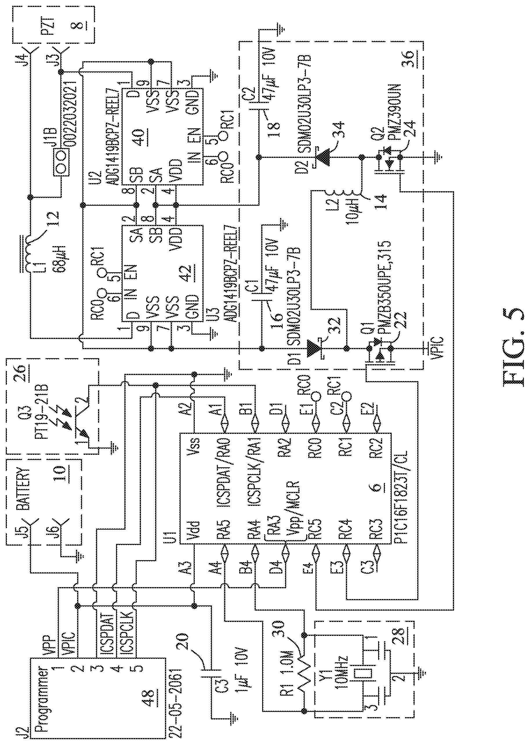
FIG. 5 shows a circuit diagram of the acoustic transmission device of the present invention.
DETAILED DESCRIPTION
A new acoustic transmission (tag) device and process are disclosed for identification and remote tracking of various small hosts including, e.g., juvenile sturgeon, and other deep-water and underwater hosts in up to three dimensions (3D) (i.e., X-Y-Z coordinates). In the following description, embodiments of the present invention are described by way of illustration of the best mode contemplated for carrying out the invention. Various components including, e.g., a transducer, tag and drive circuitry, and a power source are described that address specific performance requirements (e.g., size, mass, signal intensity, range, and tag lifetime). It will be apparent that the invention is amenable to various permutations, modifications, and alternative constructions. It should be understood that there is no intention to limit the present invention to specific forms disclosed herein, but, on the contrary, the present invention is to intended cover all modifications, alternative constructions, and equivalents falling within the scope of the present invention as defined in the claims. Therefore the description should be seen as illustrative and not limiting.
Acoustic tags of the present invention may include various form factors and shapes that allow the tags to be attached to selected hosts for selected applications. However, shapes are not intended to be limited. The term "form factor" used herein refers to the physical arrangement, configuration, and dimensions of electrical components in the acoustic tags and the capsule that contains the device components. The term "host" refers to inanimate or animate objects to which the acoustic tag may be attached for tracking and/or identification. Inanimate hosts include, but are not limited to, e.g., propelled objects (e.g., robots), stationary objects, moveable objects, and transportable objects. Animate hosts may include, but are not limited to, e.g., aquatic species including, e.g., marine and freshwater animals, deep water hosts (e.g., juvenile sturgeon, lamprey, and eels), divers, underwater mammals, and other living hosts. The present invention will now be described with reference to tracking of an exemplary deep-water host, i.e., juvenile sturgeon. However, it should be understood that the invention is not intended to be limited thereto. As discussed above, acoustic tags of the present invention are well suited for a wide variety of applications and tracking of different hosts. No limitations are intended.
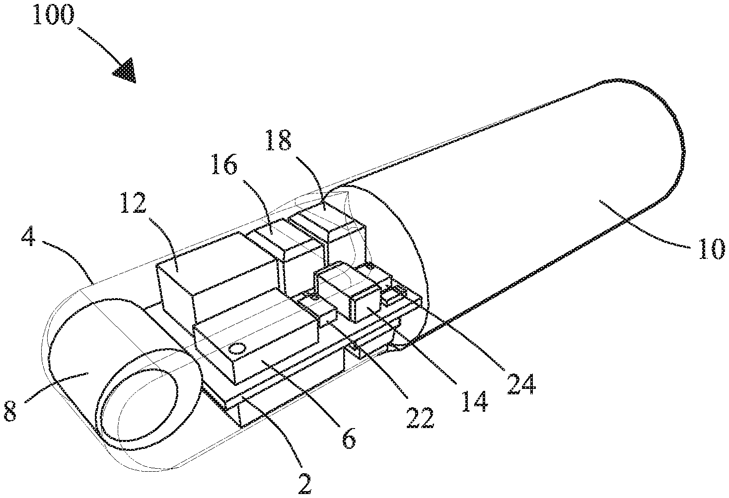
FIG. 1 is a perspective view of a new acoustic transmission device (acoustic tag) 100 of the present invention. In the exemplary embodiment, acoustic tag 100 may include an elongated or cylindrical shape that permits the tag to be easily implanted in, or attached to, the selected host. Approaches for attachment are not limited. TABLE 1 lists exemplary parameters of the new acoustic tag.
TABLE-US-00001 TABLE 1 Dimensions (Length .times. Diameter): 24.2 mm .times. O5.0 mm* Dry Weight: 720 mg Volume: 429 mm.sup.3 Source Level: 159-163 dB (re: 1 .mu.Pa @ 1 meter) Tag lifetime: 98-156 days at 5-second pulse rate interval (163 dB and 159 dB, respectively) Tag lifetime: 285-365 days at 15-second pulse rate interval (163 dB and 161 dB, respectively) Transmission Range: Up to 500 meters (163 dB) *O is an engineering unit for diameter, given here in millimeters.
In the exemplary embodiment, tag 100 may include a length of 24.2 mm and a maximum diameter of 5.0 mm. The front end of the tag may include a narrower dimension than the back end of the tag and may include a relatively flat profile to minimize weight of the tag. The acoustic tag includes a compact volume, and a mass of about 720 mg in air. Tag 100 further includes a unique tag circuit that drives transmission of the acoustic signal from the PZT, a power source with a greater power output, an enhanced and adjustable acoustic signal intensity (or source level), a selectable and longer tag lifetime, and a longer transmission range for tracking selected hosts. The acoustic transmission signal may be adjusted to provide various detection ranges and tag lifetimes.
FIG. 2 is a block diagram showing exemplary components of acoustic tag 100 of the present invention and associated electrical inputs and outputs. Tag 100 may include a power source (e.g., battery) 10 that powers components of the acoustic tag. Power source 10 may be a custom lithium carbon fluoride battery of a similar design to that described in U.S. application Ser. No. 14/014,035. Each laminate may include an anode and a cathode positioned between polymer separators that electrically isolate the cathode from the anode in the laminate. The separator may include micro-porous polypropylene. The cathode may include, or be constructed of, e.g., carbon fluoride and a conducting carbon within a binder affixed at a selected thickness to a current collector. The binder may include, e.g., polytetrafluoroethylene (PTFE). The anode may be constructed of lithium metal. The power source may be filled with an electrolyte such as, e.g., lithium hexafluorophosphate (LiPF.sub.6) disbursed in a selected volume ratio of ethylene carbonate (EC) and dimethyl carbonate (DMC). In the exemplary embodiment, power source may be of a larger size that provides a greater power output of up to about 80 mAh and a longer tag lifetime. In the instant design, power source 10 may include a plurality of laminates configured to supply a selectable output voltage between about 1.8 volts (1.8 V) to about 3.0 volts (3.0 V).
Tag 100 may also include a programmable microcontroller 6 (U1) (e.g., a model PIC16F1823T/CL 8-bit, 8K flash, programmable microcontroller in a chip-scale package, Microchip Technology, Chandler, Ariz., USA) that provides operational control of components of acoustic tag 100. Tag components are configured to generate and deliver an acoustic signal at a desired modulation or resonance frequency (e.g., 416.7 kHz) that is transmitted from the acoustic tag.
Resonator 28 (Y1) (e.g., a model CSTCE10M0G52-R0, 10 MHz ceramic resonator, Murata Manufacturing Co., Ltd., Nagaokakyo, Kyoto Prefecture, Japan) may be coupled on the input side of microcontroller 6 (U1) to generate a clock signal of a selected precision (e.g., .+-.0.5% tolerance or better) that controls operation of controller (U1) 6 and other components of acoustic tag 100.
A phototransistor (Q3) 26 (e.g., a model PT19-21B, flat black mini SMD phototransistor, Everlight Electronics Co., Ltd., New Taipei City, Taiwan) sensitive to optical or infrared radiation may be coupled on the input side of microcontroller 6 to receive configuration commands from an external computer.
Tag 100 may further include a dual boost converter sub-circuit 36 that couples to two analog switches 40 (U2) and 42 (U3). Analog switch 42 (U3) may be coupled to a high-efficiency resonance inductor 12 (L1) (e.g., a 10 uH, 80 MAmp, 20% tolerance inductor, Coilcraft, Cary, Ill., USA). Analog switch 40 (U2) and resonance inductor 12 (L1) may be coupled to piezoelectric transducer 8. The dual boost converter sub-circuit, two analog switches, and resonance inductor together generate a drive voltage that drives transmission of the acoustic signal from piezoelectric transducer 8 at a selected modulation or resonance frequency, e.g., 416.7 kHz.
Dual boost converter sub-circuit 36 also controls the intensity of the acoustic signal delivered from piezoelectric transducer 8. The signal intensity is selectable between about 159 dB and about 163 dB. Selection of the power source voltage and the acoustic signal intensity provides a selectable tag lifetime.
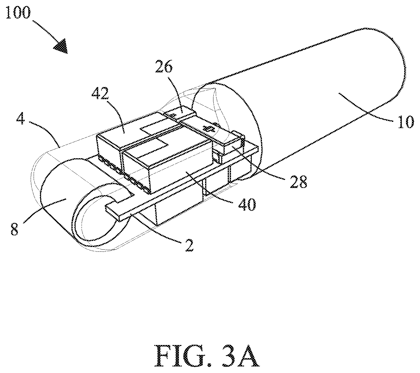
Components of tag 100 may be selected to reduce physical dimensions and weight of the tag, and may be coupled to both sides of a circuit board 2 as shown in FIG. 3A and FIG. 4A described hereafter. Circuit board 2 may be constructed of rigid board materials (.about.0.02 cm thickness) such as FR4 boards, or flexible board materials (.about.0.01 cm thickness) such as flex boards.
FIGS. 3A-3B present different top-side views of circuit board 2 showing position of selected components of acoustic tag 100. In these figures, piezoelectric transducer 8 is shown electrically coupled to circuit board 2, e.g., at a forward end of acoustic tag 100 such that the acoustic signal may be transmitted free of interference from or obstruction by other tag components. Power source 10 may be coupled to circuit board 2 at an end opposite piezoelectric transducer 8 to power operation of piezoelectric transducer 8 and other tag components. However, location is not intended to be limited.
Resonator 28 (Y1) (e.g., a 10 MHz ceramic resonator described previously in reference to FIG. 2) may be coupled to microcontroller 6 to control timing of operation of tag components. Phototransistor 26 (Q3) may be positioned to receive configuration commands from a source computer. Analog switches 40 (U2) and 42 (U3) may be positioned to deliver a drive voltage to PZT 8 of about 20 volts (peak-to-peak) directly to piezoelectric transducer 8, or to deliver the same drive voltage across a resonance inductor 12 (L1) to piezoelectric transducer 8 as described previously herein.
Tag 100 components may be encapsulated within a coating composed of a thermosetting polymer such as an epoxy (e.g., EPO-TEK.RTM. 301 epoxy, Epoxy Technology Inc., Bellerica, Mass., USA) or a resin (e.g., Scotchcast.RTM. Electrical Resin 5, 3M Company, St. Paul, Minn., USA) that forms a capsule 4.
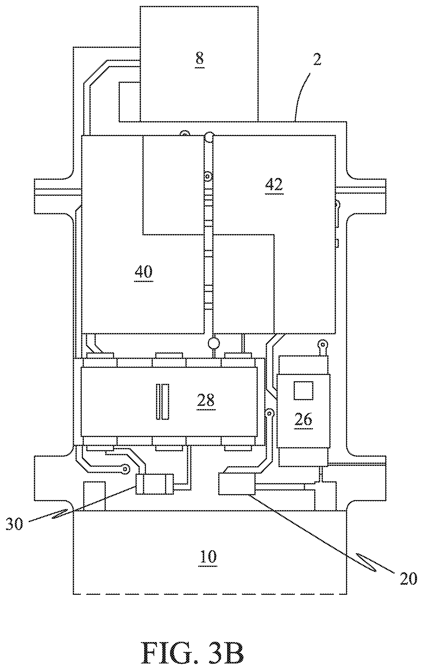
In FIG. 3B, a resistor 30 (R1) (e.g., a 1.0 Mohm, 1/20 W, 5% tolerance, SMD resistor, Vishay Intertechnology, Inc., Malvern, Pa., USA) may be coupled in parallel with resonator 28 (Y1) to stabilize the frequency of resonator 28 (Y1).
A bypass capacitor 20 (C3) (e.g., a model CL03A105MP3NSNC, 1-.mu.F, 10-volt, 20% tolerance, X5R dielectric, and 0201 size tantalum capacitor, Samsung Electro-Mechanics America, Inc., Irvine, Calif., USA) may be coupled to controller 6 and power source 10 to filter electronic noise and current spikes stemming from components on circuit board 2. As will be appreciated by those of ordinary skill in the art, electrical components may be positioned where needed. No limitations are intended.
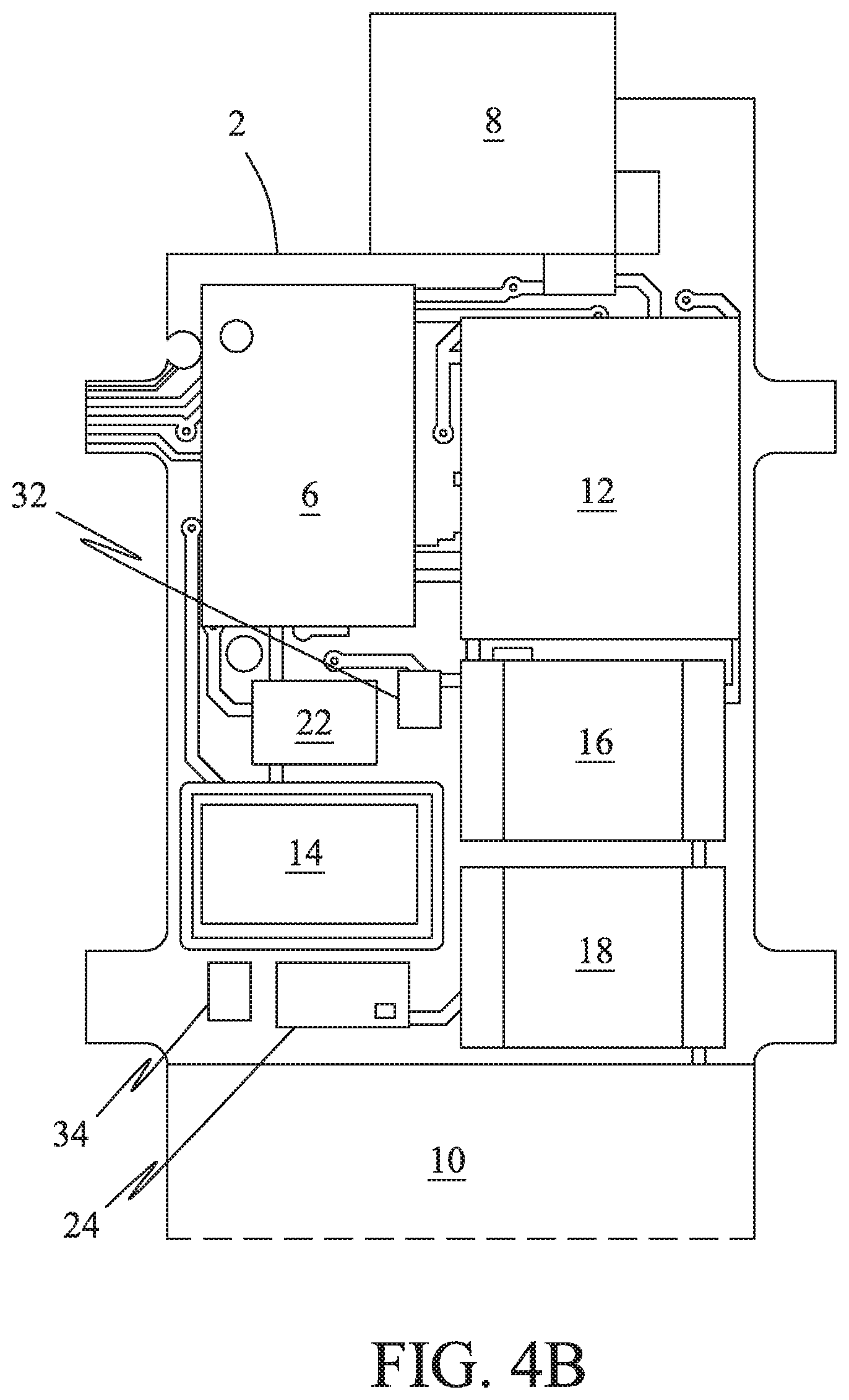
FIGS. 4A-4B are different bottom-side views of circuit board 2 showing position of selected components of acoustic tag 100. Piezoelectric transducer 8 and power source 10 may be coupled as described previously (see FIG. 3A-3B).
Microcontroller 6 (U1) may control operation of the components of the tag. In the exemplary embodiment, microcontroller 6 (U1) is shown positioned adjacent piezoelectric transducer 8, but position is not intended to be limited thereto.
A first transistor 22 (Q1) (e.g., a model PMZB350UPE-315, 20-volt, p-channel MOSFET, NXP Semiconductors, San Jose, Calif., USA), a first capacitor 16 (C1) (e.g., a 47 uF, 10-volt, 20% tolerance, X5R dielectric, and 0805 size ceramic capacitor, TDK Corp., Minato, Tokyo, JP), and an inductor 14 (L2) (e.g., a 10 uH, 80 MAmp, 20% tolerance, and 0603 size inductor, TDK Corp., Minato, Tokyo, JP) are components of the dual boost converter sub-circuit 36. These components generate the negative output voltage (e.g., about -3 volts), and couple electrically to analog switches 40 (U2) and 42 (U3) described previously in reference to FIG. 2 and FIGS. 3A-3B.
A second transistor 24 (Q2) (e.g., a 30-volt, 1.78 A, N-channel MOSFET, Fairchild Semiconductor, Inc., Dallas, Tex., USA) and a second capacitor 18 (C2) (e.g., a 47 uF, 10-volt, 20% tolerance, X5R dielectric, and 0805 size ceramic capacitor, TDK Corp., Minato, Tokyo, JP), are additional components of the dual boost converter sub-circuit 36. These components share inductor 14 (L2) described previously above and together generate the positive output voltage (e.g., about +7 volts), and couple electrically to analog switches 40 (U2) and 42 (U3) described previously in reference to FIG. 2 and FIGS. 3A-3B.
Analog switch 42 (U3) may couple to piezoelectric transducer 8 through inductor 12 (L1) to increase the drive voltage across the piezoelectric transducer.
In FIG. 4B, a first diode 32 (D1) (e.g., a 30-volt, 0.1 A, 2DFN Schottky Diode 0201, Diodes, Inc., Plano, Tex., USA) and a second diode 34 (D2) (e.g., a 30-volt, 0.1 A, 2DFN Schottky Diode 0201, Diodes, Inc., Plano, Tex., USA) are additional components of the dual boost converter sub-circuit 36. First diode 32 (D1) assists in the generation of the negative voltage (e.g., -3 volts), and second diode 34 (D2) assists in the generation of the positive voltage (e.g., +7 volts).
Tag Circuit
FIG. 5 shows an exemplary tag circuit for acoustic tags of the present invention showing components described previously above. Components may be located on, or coupled to, a circuit board described previously in reference to FIG. 2. The tag circuit may include preferred trace line widths of about 0.01 cm (0.003 inches), but are not intended to be limited.
Configuration commands for programming microcontroller 6 may be received directly from an external computer (not shown), e.g., through an Integrated Circuit Serial Programmer (ICSP) module 48 (e.g. a MPLAB ICD 3 programmer, Microchip Technologies, Chandler, Ariz., USA) that couples to microcontroller 6. Programmer (ICSP) module 48 may couple to the external computer through a programming connector (e.g., a model 22-05-2061, 6-position connector, Molex Connector Corp., Lisle, Ill., USA) (not shown). The programming connector may be detached from the circuit board during assembly of the acoustic tag to reduce the final volume of the assembled tag.
Configuration and programming information may also be delivered remotely (e.g., optically) from the external computer through phototransistor 26 (Q3) and into controller 6 through a selected input pin. Pins are not intended to be limited.
Bypass capacitor 20 (C3) may be coupled to controller 6 and power source 10 to filter electronic noise and current spikes from components on the circuit board.
Resonator 28 (Y1) delivers a clock signal that controls the timing of delivery of a positive channel drive signal (PCH-DRV) and a negative channel drive signal (NCH-DRV) to dual boost converter sub-circuit 36 described hereafter. A resistor 30 (R1) may be placed in parallel with resonator 28 (Y1) to stabilize the frequency and clock signal of resonator 28 (Y1).
Dual boost converter sub-circuit 36 may include a first transistor 22 (Q1), an inductor 14 (L2), a first diode 32 (D1), and a first capacitor 16 (C1) that together generate a negative output voltage (e.g., -3 volts). Microcontroller 6 may toggle the PCH-DRV signal to alternately build up current through inductor 14 (L2), and then discharges capacitor 16 (C1) through diode 32 (D1). Magnitude of the positive output voltage depends in part on the length of time that microcontroller 6 toggles the PCH-DRV signal. Microcontroller 6 may hold the NCH-DRV signal at a positive voltage during operation so that a second transistor 24 (Q2) described hereafter can conduct current.
Dual boost converter sub-circuit 36 may include second transistor 24 (Q2), inductor 14 (L2), second diode 34 (D2), and second capacitor 18 (C2) that together generate a positive output voltage (e.g., +7 volts). Microcontroller 6 toggles the NCH-DRV signal to alternately build up current through inductor 14 (L2), and then charge capacitor 18 (C2) through diode 34 (D1). The magnitude of the positive output voltage generally depends on the length of time that the microcontroller toggles the NCH-DRV signal. Microcontroller 6 (U1) may hold the PCH-DRV signal at zero voltage during this operation so that first transistor 22 (Q1) can conduct current.
Dual boost converter sub-circuit 36 may couple to two analog switches 40 (U2) and 42 (U3). The two analog switches respectively receive the positive and negative output voltages from the dual boost converter sub-circuit 36. The analog switches switch between these two voltages alternately in succession, under the control of microcontroller 6 (U1), to generate a selected (drive) voltage from the tag circuit that is delivered to piezoelectric transducer 8. Analog switch 40 (U2) may couple to one terminal (e.g., negative terminal) of piezoelectric transducer 8. Analog switch 42 (U3) may couple through a resonance inductor 12 (L1) to another terminal (e.g., positive terminal) of piezoelectric transducer 8. The drive voltage may be delivered from analog switch 42 (U3) through resonance inductor 12 (L1) to piezoelectric transducer 8 to generate the acoustic signal transmitted from piezoelectric transducer 8. Resonance inductor 12 (L1) is configured to increase the voltage delivered at the terminals of piezoelectric transducer 8. The acoustic signal transmitted from piezoelectric transducer 8 may have a selected modulation frequency (e.g., 416.7 kHz). The value of inductor 12 (L1) may be selected such that the inductance partially or fully cancels out characteristic capacitances of piezoelectric transducer 8 at the selected modulation frequency. The resulting voltage at each terminal of piezoelectric transducer 8 may go above the positive drive voltage and below the negative drive voltage. As will be appreciated by those of ordinary skill in the art, modulation frequencies may be varied and hence are not intended to be limited to the exemplary value described herein.
Tag Lifetimes
Lifetimes of acoustic tags of the present invention depend in part on the size of the power source (battery) 10 described previously in reference to FIG. 5. However, for a given power source size, in general, tag lifetimes are selectable by selecting: 1) the PRI for transmission of the acoustic signal, 2) the intensity of the acoustic signal, or 3) both the PRI and the intensity of the acoustic signal.
Within the selectable range of acoustic intensity between about 159 dB and about 163 dB, tag lifetimes may be estimated from empirical equation [1]:
##EQU00001##
Here, lifetime (T) has units of days. (V.sub.batt) is the battery voltage and has units of volts. (C.sub.batt) is the battery capacity in units of milli-Amp-Hours (mAh). (SL) is the acoustic intensity (or source level) in units of dB. (I.sub.s) is the constant static current that flows through the tag circuit (FIG. 5) in units of micro-Amps. (t.sub.0) is the PRI in units of seconds. TABLE 2 lists exemplary constants that may be employed for calculating tag lifetimes (T) at a PRI (t.sub.0) of 5 seconds and a signal strength (intensity) of 163 dB:
TABLE-US-00002 TABLE 2 Item Values V.sub.batt 3.0 V C.sub.batt 56 mAh SL 163 dB t.sub.0 5 seconds I.sub.s 0.4 .mu.A
From Equation [1], tag lifetime (T) may be calculated at about 98 days using identified variable values. Acoustic tags of the present invention are configured to maintain a selected energy expenditure (e.sub.pulse) for each transmission of the acoustic signal even as battery voltage decreases gradually over time. Energy expenditure (e.sub.pulse) values may be less than or equal to about 385 .mu.J per transmission at a signal intensity of 163 dB, and less than or equal to about 283 .mu.J per transmission at a signal intensity of 161 dB.
Actual tag lifetimes (T) may be longer than calculated lifetimes based on nominal energy expenditure (e.sub.pulse) values. As an example, at a signal intensity (strength) setting of 163 dB, an empirical energy consumption value of 351 .mu.J per transmission may be used instead of the nominal 385 .mu.J for a more accurate estimate of tag lifetime. In another example, at a signal strength setting of 161 dB, an empirical energy consumption value of 269 .mu.J may be used instead of the nominal 283 .mu.J.
TABLE 3 lists experimental and projected tag lifetimes for acoustic tags of the present invention at selected PRIs and selected signal intensities.
TABLE-US-00003 TABLE 3 PRI (t.sub.0) (seconds) 0.5 1 5 10 15 Tag @163 dB 8.9 19.9 98 193 285 Lifetime (T) @161 dB 12.9 25.9 127 249 365 (days) Note: Experimental ---------------------Projected values---------------- values
Lifetimes (T) of acoustic tags of the present invention are selectable. Shorter tag lifetimes and longer tag lifetimes may be selected. In the table, it can be seen that for a selected signal intensity, tag lifetime may be selected by varying the PRI. For example, at a signal intensity of 163 dB, tag lifetime corresponding to a 5 sec PRI is about 98 days; tag lifetime corresponding to a 15 sec PRI is about 285 days. It will be readily understood by those of ordinary skill in the art that various signal intensities may be selected with their corresponding lifetimes at selected PRIs to meet specific tracking needs for selected hosts and/or for selected applications. No limitations are intended. For example, for a tag with a signal intensity set at 161 dB, tag lifetime may be at least about 12.9 days using a PRI of 0.5 seconds, at least about 127 days using a PRI of 5 seconds, or about 365 days using a PRI of 15 seconds.
Beam Transmission Patterns
Beam transmission patterns of the piezoelectric transducer are described, e.g., in U.S. application Ser. No. 14/014,035 filed 29 Aug. 2013.
Transmission Detection Range
Acoustic signals transmitted by tags of the present invention may include selected detection ranges. Tag signals may be encoded to provide maximum strength and to improve range and resolution. In locations with a relatively small amount of background noise, such as the middle of a lake, signals may be transmitted up to about 500 meters. The present tag delivers a higher source level output to provide for the 500-meter detection range than used in previous tags. TABLE 4 lists projected detection ranges at two exemplary intensity values of 163 dB and 161 dB for three different signal transmission spread scenarios and an assumed noise level of 97 dB in a quiet environment (e.g. the forebay of a dam). However, no limitations are intended by the illustrative example.
TABLE-US-00004 TABLE 4 Detection range (meters) Spherical Realistic* Cylindrical Forebay @163 dB 726 512 770 @161 dB 249 475 277 *A noise level of 97 dB is presumed based on actual noise level measurements.
Data suggest a transmission detection range of 500 meters or better may be achieved at an acoustic signal intensity selected from 159 dB to 163 dB. In locations with larger background noise (e.g., immediately downstream of a dam spillway), signals may be transmitted about 100 meters. However, distances are not intended to be limited.
Coding and Activation
Tags of the present invention may be programmed with one or more tag codes of a selectable code length. The microcontroller (FIG. 2) may also contain internal sensors such as temperature sensors that collect additional data from the host and surrounding environment. As an example, a 5-bit temperature value or other sensor values with selected bit-lengths may be input from selected sensors into one or more tag codes that are then transmitted from the piezoelectric transducer. Coding and sensors are described in U.S. application Ser. No. 14/014,035 filed 29 Aug. 2013.
Methods and locations for attachment of acoustic tags to selected hosts are not limited. Acoustic tags may be attached, e.g., to the outside of the host (e.g., to the clothing or scuba gear of a human host), to an inanimate object, to a self-propelled object such as a robot, attached internally to the host (e.g., inserted within an object, surgically implanted, or injected). No limitations are intended.
Applications for acoustic tags of the present invention may include, but are not limited to, e.g., survival studies; monitoring migration/passage/trajectories; tracking host behavior or location in two dimensions (2D) or three dimensions (3D); measuring bypass effectiveness at dams and other passages; observing predator/prey dynamics; helping public utility agencies, private firms, and state and federal agencies meet fishery or other regulations; and other applications. Applications are not intended to be limited.
The present invention delivers unsurpassed advantages not obtained in previous designs and open up a broad array of tag uses and applications not yet realized. The high-efficiency piezoelectric transducer drive circuit in the instant design enhances energy conversion efficiency and reduces number of dedicated components, all while maintaining the same source level performance. Fewer components decreases the energy required to power the tag, which permits yet smaller acoustic tags with a lower mass to be constructed for even smaller hosts and applications.
While the invention has been described with what is presently considered to be the most practical and preferred embodiments, many changes, modifications, and equivalent arrangements may be made without departing from the invention in its true scope and broader aspects. Thus, the scope is expected to be accorded the broadest interpretation relative to the appended claims. The appended claims are therefore intended to cover all such changes, modifications, equivalent structures, and products as fall within the scope of the invention. No limitations are intended.
* * * * *
References
uspto.report is an independent third-party trademark research tool that is not affiliated, endorsed, or sponsored by the United States Patent and Trademark Office (USPTO) or any other governmental organization. The information provided by uspto.report is based on publicly available data at the time of writing and is intended for informational purposes only.
While we strive to provide accurate and up-to-date information, we do not guarantee the accuracy, completeness, reliability, or suitability of the information displayed on this site. The use of this site is at your own risk. Any reliance you place on such information is therefore strictly at your own risk.
All official trademark data, including owner information, should be verified by visiting the official USPTO website at www.uspto.gov. This site is not intended to replace professional legal advice and should not be used as a substitute for consulting with a legal professional who is knowledgeable about trademark law.