Embolic protection device
Belson A
U.S. patent number 10,736,728 [Application Number 15/487,386] was granted by the patent office on 2020-08-11 for embolic protection device. This patent grant is currently assigned to Emboline, Inc.. The grantee listed for this patent is Emboline, Inc.. Invention is credited to Amir Belson.


| United States Patent | 10,736,728 |
| Belson | August 11, 2020 |
Embolic protection device
Abstract
The embolic protection device (10) has an expandable tubular structure supporting a filter mesh material (12). The embolic protection device is compressed to a small diameter for insertion into a patient's aorta, then is expanded within the aorta with the filter mesh material positioned to allow blood to enter sidebranch vessels connected to the aorta and to prevent embolic material from entering the sidebranch vessels. The filter mesh material may be configured with waves or undulations (26) for increased surface area and/or with two layers of mesh material to provide additional protection against embolization and to prevent inadvertent occlusion of the sidebranch vessels.
| Inventors: | Belson; Amir (Saryou, IL) | ||||||||||
|---|---|---|---|---|---|---|---|---|---|---|---|
| Applicant: |
|
||||||||||
| Assignee: | Emboline, Inc. (Santa Cruz,
CA) |
||||||||||
| Family ID: | 31978308 | ||||||||||
| Appl. No.: | 15/487,386 | ||||||||||
| Filed: | April 13, 2017 |
Prior Publication Data
| Document Identifier | Publication Date | |
|---|---|---|
| US 20170216010 A1 | Aug 3, 2017 | |
Related U.S. Patent Documents
| Application Number | Filing Date | Patent Number | Issue Date | ||
|---|---|---|---|---|---|
| 14175042 | Feb 7, 2014 | 10016267 | |||
| 13648992 | May 20, 2014 | 8728114 | |||
| 13347046 | Nov 13, 2012 | 8308754 | |||
| 10493854 | Feb 14, 2012 | 8114114 | |||
| PCT/US03/26938 | Aug 27, 2003 | ||||
| 60406492 | Aug 27, 2002 | ||||
| Current U.S. Class: | 1/1 |
| Current CPC Class: | A61F 2/013 (20130101); A61F 2/011 (20200501); A61F 2210/0076 (20130101); A61F 2230/0065 (20130101); A61B 17/00234 (20130101); A61B 18/1492 (20130101); A61F 2250/0067 (20130101); A61F 2002/016 (20130101); A61B 2017/00243 (20130101); A61F 2002/018 (20130101); A61F 2230/0006 (20130101); A61F 2230/0069 (20130101) |
| Current International Class: | A61F 2/01 (20060101); A61B 17/00 (20060101); A61B 18/14 (20060101) |
References Cited [Referenced By]
U.S. Patent Documents
| 4723549 | February 1988 | Wholey et al. |
| 4790809 | December 1988 | Kuntz |
| 5108419 | April 1992 | Reger et al. |
| 5197485 | March 1993 | Grooters |
| 5769816 | June 1998 | Barbut et al. |
| 5769819 | June 1998 | Schwab et al. |
| 5797880 | August 1998 | Erskine |
| 5800525 | September 1998 | Bachinski et al. |
| 6013051 | January 2000 | Nelson |
| 6117154 | September 2000 | Barbut et al. |
| 6139517 | October 2000 | Macoviak et al. |
| 6152144 | November 2000 | Lesh et al. |
| 6254563 | July 2001 | Macoviak et al. |
| 6258120 | July 2001 | McKenzie et al. |
| 6348063 | February 2002 | Yassour et al. |
| 6355051 | March 2002 | Sisskind et al. |
| 6361545 | March 2002 | Macoviak |
| 6371935 | April 2002 | Macoviak et al. |
| 6461370 | October 2002 | Gray et al. |
| 6499487 | December 2002 | McKenzie et al. |
| 6537297 | March 2003 | Tsugita et al. |
| 6682543 | January 2004 | Barbut et al. |
| 6695864 | February 2004 | Macoviak et al. |
| 6746469 | June 2004 | Mouw |
| 6808520 | October 2004 | Fourkas et al. |
| 7044958 | May 2006 | Douk et al. |
| 7232453 | June 2007 | Shimon |
| 7235060 | June 2007 | Kraus |
| 7537600 | May 2009 | Eskuri et al. |
| 7758606 | July 2010 | Streeter et al. |
| 7766932 | August 2010 | Melzer et al. |
| 8052717 | November 2011 | Mujkanovic et al. |
| 8114114 | February 2012 | Belson |
| 8123779 | February 2012 | Demond et al. |
| 8298258 | October 2012 | Anderson et al. |
| 8308754 | November 2012 | Belson |
| 8337519 | December 2012 | Wasicek et al. |
| 8382788 | February 2013 | Galdonik et al. |
| 8414482 | April 2013 | Belson |
| 8420902 | April 2013 | Gilsinger et al. |
| 8430904 | April 2013 | Belson |
| 8679149 | March 2014 | Belson |
| 8728114 | May 2014 | Belson |
| 8740930 | June 2014 | Goodwin et al. |
| 8968354 | March 2015 | Wang et al. |
| 9107734 | August 2015 | Belson |
| 9144485 | September 2015 | Bergheim et al. |
| 9492265 | November 2016 | Russell et al. |
| 9744023 | August 2017 | Wang et al. |
| 2001/0044632 | November 2001 | Daniel et al. |
| 2002/0004667 | January 2002 | Adams et al. |
| 2002/0045916 | April 2002 | Gray et al. |
| 2002/0058964 | May 2002 | Addis |
| 2002/0128680 | September 2002 | Pavlovic |
| 2003/0040736 | February 2003 | Stevens et al. |
| 2003/0100940 | May 2003 | Yodfat |
| 2003/0171803 | September 2003 | Shimon |
| 2004/0034380 | February 2004 | Woolfson et al. |
| 2004/0073253 | April 2004 | Morrill et al. |
| 2004/0138692 | July 2004 | Phung et al. |
| 2004/0215167 | October 2004 | Belson |
| 2004/0225354 | November 2004 | Allen et al. |
| 2005/0010246 | January 2005 | Streeter et al. |
| 2005/0283186 | December 2005 | Berrada et al. |
| 2006/0287668 | December 2006 | Fawzi et al. |
| 2006/0293706 | December 2006 | Shimon |
| 2007/0027534 | February 2007 | Bergheim et al. |
| 2007/0060944 | March 2007 | Boldenow et al. |
| 2007/0073246 | March 2007 | Simon |
| 2008/0027481 | January 2008 | Gilson et al. |
| 2009/0149881 | June 2009 | Vale et al. |
| 2010/0010535 | January 2010 | Mujkanovic et al. |
| 2010/0274277 | October 2010 | Eaton |
| 2010/0312268 | December 2010 | Belson |
| 2012/0016408 | January 2012 | Barbut et al. |
| 2012/0109182 | May 2012 | Belson |
| 2012/0109183 | May 2012 | Belson |
| 2012/0271340 | October 2012 | Castellano et al. |
| 2013/0035716 | February 2013 | Belson |
| 2013/0035717 | February 2013 | Belson |
| 2013/0096606 | April 2013 | Bruchman et al. |
| 2013/0238011 | September 2013 | Belson |
| 2013/0245669 | September 2013 | Basu et al. |
| 2013/0267993 | October 2013 | Carpenter et al. |
| 2014/0058372 | February 2014 | Belson |
| 2014/0155929 | June 2014 | Belson |
| 2014/0214069 | July 2014 | Franklin et al. |
| 2014/0249568 | September 2014 | Adams et al. |
| 2015/0066075 | March 2015 | Russell et al. |
| 2015/0320540 | November 2015 | Amir |
| 2015/0366650 | December 2015 | Zi et al. |
| 2016/0317277 | November 2016 | Carpenter et al. |
| 2017/0216010 | August 2017 | Belson |
| 2017/0216011 | August 2017 | Belson |
| 2018/0206970 | July 2018 | Eggert et al. |
| 2019/0015152 | January 2019 | Howard et al. |
| 2609800 | Jan 2007 | CA | |||
| WO-03043538 | May 2003 | WO | |||
| WO-03094791 | Nov 2003 | WO | |||
| WO-2004019817 | Mar 2004 | WO | |||
Other References
|
US 6,348,062 B1, 02/2002, Hopkins et al. (withdrawn) cited by applicant . U.S. Appl. No. 14/175,042 Notice of Allowance dated May 2, 2018. cited by applicant . International search report and written opinion dated Apr. 9, 2008 for PCT/US2007/024558. cited by applicant . International search report and written opinion dated Apr. 22, 2013 for PCT/US2013/20563. cited by applicant . International search report and written opinion dated Dec. 14, 2015 for PCT/US2015/049908. cited by applicant . International search report dated Jan. 15, 2004 for PCT/US2003/026938. cited by applicant . Notice of allowance dated Feb. 26, 2013 for U.S. Appl. No. 13/648,986. cited by applicant . Notice of allowance dated Mar. 1, 2013 for U.S. Appl. No. 13/343,538. cited by applicant . Notice of allowance dated Aug. 10, 2012 for U.S. Appl. No. 13/347,046. cited by applicant . Notice of Allowance dated Nov. 1, 2013 for U.S. Appl. No. 13/648,992. cited by applicant . Notice of Allowance dated Nov. 18, 2013 for U.S. Appl. No. 13/866,887. cited by applicant . Notice of Allowance dated Nov. 23, 2011 for U.S. Appl. No. 10/493,854. cited by applicant . Office action dated Jan. 17, 2012 for U.S. Appl. No. 12/532,630. cited by applicant . Office action dated Jan. 17, 2013 for U.S. Appl. No. 13/648,992. cited by applicant . Office action dated Jan. 24, 2014 for U.S. Appl. No. 13/735,864. cited by applicant . Office action dated Feb. 11, 2009 for U.S. Appl. No. 10/493,854. cited by applicant . Office action dated Feb. 26, 2008 for U.S. Appl. No. 10/493,854. cited by applicant . Office action dated Feb. 26, 2014 for U.S. Appl. No. 12/532,630. cited by applicant . Office action dated Mar. 13, 2013 for U.S. Appl. No. 12/532,630. cited by applicant . Office action dated Apr. 7, 2016 for U.S. Appl. No. 14/175,042. cited by applicant . Office action dated Apr. 10, 2012 for U.S. Appl. No. 13/343,538. cited by applicant . Office action dated Apr. 10, 2013 for U.S. Appl. No. 12/532,630. cited by applicant . Office action dated Jun. 10, 2013 for U.S. Appl. No. 12/532,630. cited by applicant . Office action dated Jun. 22, 2016 for U.S. Appl. No. 14/175,042. cited by applicant . Office action dated Jul. 12, 2011 for U.S. Appl. No. 10/493,854. cited by applicant . Office action dated Jul. 17, 2013 for U.S. Appl. No. 13/735,864. cited by applicant . Office action dated Jul. 23, 2013 for U.S. Appl. No. 13/648,992. cited by applicant . Office action dated Jul. 23, 2013 for U.S. Appl. No. 13/866,887. cited by applicant . Office action dated Aug. 18, 2017 for U.S. Appl. No. 14/175,042. cited by applicant . Office action dated Aug. 20, 2010 for U.S. Appl. No. 10/493,854. cited by applicant . Office action dated Aug. 25, 2015 for U.S. Appl. No. 14/175,042. cited by applicant . Office action dated Sep. 14, 2011 for U.S. Appl. No. 10/493,854. cited by applicant . Office action dated Nov. 6, 2012 for U.S. Appl. No. 12/532,630. cited by applicant . Office action dated Nov. 6, 2015 for U.S. Appl. No. 14/801,850. cited by applicant . Office action dated Nov. 19, 2013 for U.S. Appl. No. 12/532,630. cited by applicant . Office action dated Dec. 11, 2012 for U.S. Appl. No. 13/343,538. cited by applicant . U.S. Appl. No. 14/175,042 Office Action dated Dec. 4, 2017. cited by applicant . Office action dated Mar. 8, 2019 for U.S. Appl. No. 15/487,392. cited by applicant. |
Primary Examiner: Anderson; Gregory A
Attorney, Agent or Firm: Wilson Sonsini Goodrich & Rosati
Parent Case Text
CROSS-REFERENCE TO RELATED APPLICATION
This application is a continuation of U.S. patent application Ser. No. 14/175,042, filed on Feb. 7, 2014, which is a continuation of U.S. patent application Ser. No. 13/648,992, filed Oct. 10, 2012, which is a continuation of U.S. patent application Ser. No. 13/347,046, filed Jan. 10, 2012, (now U.S. Pat. No. 8,308,754), which is a continuation of U.S. patent application Ser. No. 10/493,854, filed Apr. 27, 2004, (now U.S. Pat. No. 8,114,114), which is a National Stage Application of PCT/US2003/26938, filed Aug. 27, 2003, which claims the benefit of U.S. Provisional Application No. 60/406,492, filed Aug. 27, 2002, the full disclosures of which are incorporated herein by reference.
Claims
What is claimed is:
1. An embolic protection device for deployment within a patient's aorta comprising: a panel of filter mesh material having a periphery surrounding the panel; a wire frame encircling the periphery of the panel of filter mesh material; and a handle or cannula attached to the wire frame for insertion through peripheral vasculature or an aortotomy; wherein the panel of filter mesh material encircled by the wire frame has a compressed position with a small diameter for insertion into the patient's aorta and is configured to expand to a larger size within the patient's aorta such that the wire frame encircles and the filter mesh material covers ostia of sidebranch vessels connected to the patient's aorta and allow blood to enter the sidebranch vessels and prevents embolic material from entering the sidebranch vessels.
2. The embolic protection device of claim 1, further comprising at least one wire hoop attached to the wire frame and configured for supporting the embolic protection device within the patient's aorta.
3. The embolic protection device of claim 2, wherein the at least one wire hoop expands away from a plane of the panel of filter mesh material to a deployed position configured to further support the wire frame and the panel of filter mesh material within the aorta.
4. The embolic protection device of claim 3, wherein a portion of the at least one wire hoop extending away from the panel of filter mesh material is not covered by or directly attached to the filter mesh material.
5. The embolic protection device of claim 1, wherein at least a portion of the device is coated with an anti-thrombogenic coating.
6. The embolic protection device of claim 5, wherein the anti-thrombogenic coating comprises heparin.
7. The embolic protection device of claim 1, wherein the panel of filter mesh material comprise resilient wires and/or fibers woven to form a filter mesh.
8. The embolic protection device of claim 1, wherein the wire frame encircling the periphery of the panel is self-expanding.
9. The embolic protection device of claim 1, wherein the filter mesh material is configured with waves or undulations.
10. The embolic protection device of claim 1, wherein the filter mesh material is configured with an inner layer of filter mesh and an outer layer of filter mesh.
11. The embolic protection device of claim 10, wherein the inner layer of filter mesh comprises a coarse mesh material and the outer layer of filter mesh comprises a fine mesh material.
12. A system for embolic protection, said system comprising: an embolic protection device according to claim 1; and a delivery tube sized and configured to hold the panel of filter mesh material in its compressed position.
13. A method of providing embolic protection for the arch vessels of a patient's aorta, said method comprising: introducing a panel of filter mesh material into the patient's aortic arch through a peripheral artery or an aortotomy, wherein a wire frame encircles a periphery of the panel of filter mesh material; and positioning the wire frame to encircle ostia of the arch vessels so that the panel of filter mesh material covers and conforms to the ostia of the arch vessels such that the filter mesh material allows blood to enter the arch but prevents embolic material from entering the renal arteries.
14. The method of claim 13, wherein the panel of filter mesh material is compressed in a delivery tube when introduced into the patient's aortic arch and released from the tube to self-expand and conform to the ostia of the arch vessels.
15. The method of claim 14, wherein the wire frame is attached to a handle or cannula for insertion through peripheral vasculature or an aortotomy.
16. The method of claim 15, wherein the wire frame is self-expanding the handle or cannula is attached to the wire frame.
17. The method of claim 13, wherein the panel of filter mesh material is configured with waves or undulations.
18. The method of claim 13, wherein the panel of filter mesh material is configured with an inner layer of filter mesh and an outer layer of filter mesh.
19. The method of claim 18, wherein the inner layer of filter mesh comprises a coarse mesh material and the outer layer of filter mesh comprises a fine mesh material.
20. The method of claim 13, wherein the panel is substantially flat.
Description
BACKGROUND OF THE INVENTION
Field of the Invention
The present invention relates to apparatus and methods for providing embolic protection to a patient's aortic arch vessels during cardiac surgery and interventional cardiology procedures.
Cerebral embolism is a known complication of cardiac surgery, cardiopulmonary bypass and catheter-based interventional cardiology and electrophysiology procedures. Embolic particles, which may include thrombus, atheroma and lipids, may become dislodged by surgical or catheter manipulations and enter the bloodstream, embolizing in the brain or other vital organs downstream. Cerebral embolism can lead to neuropsychological deficits, stroke and even death. Prevention of cerebral embolism would benefit patients and improve the outcome of these procedures.
Previous devices for preventing cerebral embolism are described in the following U.S. patents and patent applications, which are hereby incorporated by reference: U.S. Pat. No. 6,371,935 Aortic catheter with flow divider and methods for preventing cerebral embolization, U.S. Pat. No. 6,361,545 Perfusion filter catheter, U.S. Pat. No. 6,254,563 Perfusion shunt apparatus and method, U.S. Pat. No. 6,139,517 Perfusion shunt apparatus and method, U.S. Pat. No. 6,537,297 Methods of protecting a patient from embolization during surgery, U.S. Pat. No. 6,499,487 Implantable cerebral protection device and methods of use, U.S. Pat. No. 5,769,816 Cannula with associated filter, US20030100940A1 Implantable intraluminal protector device and method of using same for stabilizing atheromas.
BRIEF SUMMARY OF THE INVENTION
The present invention takes the form of apparatus and methods for providing embolic protection to a patient's aortic arch vessels during cardiac surgery and interventional cardiology and electrophysiology procedures. Embolic particles in the aortic blood flow are prevented from entering the aortic arch vessels and carotid arteries that lead to the brain. The apparatus and methods of the present invention can also be used for embolic protection of other organ systems, such as the renal system.
In one embodiment, a stent-like embolic protection device is constructed of a self-expanding tubular mesh that may be woven out of wires or fibers or formed from a tube or sheet. The embolic protection device is compressed to a small diameter and inserted into a delivery tube or catheter, which is introduced via a peripheral artery or an aortotomy and advanced into the aortic arch. Once in place, the delivery tube is withdrawn to allow the device to expand similar to a self-expanding stent. The mesh of the device covers the ostia of the arch vessels, allowing blood to enter, but preventing potential emboli from entering the aortic arch vessels and carotid arteries. The device conforms closely to the walls of the aorta so that it will not interfere with performing cardiac surgery or interventional cardiology procedures. The embolic protection device may be collapsed and withdrawn from the aorta after the procedure or it may be left in the aorta for long-term embolic protection.
In another embodiment, the embolic protection device may be made with a flat panel of fine mesh textile fabric that is supported on a wire frame or the like. The panel of fine mesh fabric is held in place over the aortic arch vessels by the wire frame to filter out potential emboli. Being made of fabric, the device is free to conform to the ostia of the arch vessels to allow more surface area for blood flow compared to a flat panel. The wire frame may be attached to a handle or cannula for insertion through an aortotomy or to a catheter for peripheral artery insertion. In addition, the wire frame may include one or more wire hoops or a stent-like tubular structure for supporting the embolic protection device within the aortic arch.
Additional features are described which may be used with either embodiment of the embolic protection device. An embolic protection device is described with waves or undulations to provide more surface area for filtering out potential emboli and to prevent inadvertent occlusion of the arch vessels. Another embolic protection device is described with two layers of mesh material to provide additional protection against embolization and to prevent inadvertent occlusion of the arch vessels. An embolic protection device is described with an inflatable toroidal balloon for supporting the filter mesh material within the aorta. The embolic protection device or a portion of it may be coated with an antithrombogenic coating to reduce the formation of clots that could become potential emboli.
BRIEF DESCRIPTION OF THE DRAWINGS
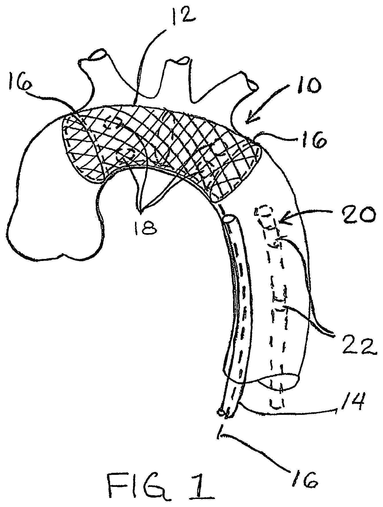
FIG. 1 shows a stent-like embolic protection device deployed within a patient's aortic arch for protecting the aortic arch vessels and carotid arteries from potential emboli.
FIG. 2 shows a stent-like embolic protection device with waves or undulations.
FIG. 3 shows a cut-away view of a stent-like embolic protection device with two layers of mesh material.
FIG. 4 shows an alternative embodiment of an embolic protection device.
FIG. 5 shows another alternative embodiment of an embolic protection device.
DETAILED DESCRIPTION OF THE INVENTION
FIG. 1 shows a stent-like embolic protection device 10 deployed within a patient's aortic arch for protecting the aortic arch vessels and carotid arteries from potential emboli. The embolic protection device 10 is made of a resilient material, either a polymer or a metal (e.g. Nitinol) or a combination of materials. The device 10 may be woven out of wires or fibers to form a tubular mesh structure 12 or by slitting and expanding a tube or sheet. Alternatively, the device 10 may be constructed with a tubular mesh structure 12 made of a flexible textile mesh with one or more wire hoops or a stent-like tubular structure for supporting the tubular mesh structure 12 within the aortic arch. The device 10 is compressible to a small diameter for insertion into the aorta via peripheral artery access or through an aortotomy. The device 10 is preferably self-expanding and, when expanded, has a generally tubular shape that conforms to the diameter and curvature of the aortic arch.
The embolic protection device 10 is compressed to a small diameter and inserted into a delivery tube or catheter 14. The delivery tube is introduced via a peripheral artery or an aortotomy and advanced into the aortic arch. Once in place, the delivery tube 14 is withdrawn to allow the device 10 to expand similar to a self-expanding stent. The mesh 12 of the device covers the ostia of the arch vessels, allowing blood to enter, but preventing potential emboli from entering the aortic arch vessels and carotid arteries. The device 10 conforms closely to the walls of the aorta so that it will not interfere with performing cardiac surgery or catheter-based interventional cardiology or electrophysiology procedures.
Alternatively, the embolic protection device 10 may be balloon-expandable. In this case, the embolic protection device 10 would be crimped or compressed onto an expandable balloon mounted on a catheter. The catheter is introduced into the aortic arch and the balloon is expanded to deploy the embolic protection device 10 in the aorta. Other volume expanding mechanisms, such as a mechanical expander, may be used in lieu of an expandable balloon.
After the procedure is completed, the embolic protection device 10 may be compressed and withdrawn from the aorta. Alternatively, the device 10 may be left in the aorta for long-term embolic protection. The device 10 may be compressed using one or more drawstrings 16 that encircle the device. The drawstrings 16 are pulled to compress the device and the device is withdrawn into the delivery tube 14 for removal. Alternatively, the embolic protection device 10 may be stretched longitudinal with the aid of a catheter, which will cause the diameter of the device to contract. Alternatively, the embolic protection device 10 may use a magnetic mechanism for compressing the device for removal. Multiple magnets 18 are arranged around the periphery of the device 10. After the procedure is completed, a catheter 20 carrying one or more strong magnets 22 is inserted through the lumen of the device 10 to compress the device around the catheter for removal.
FIG. 2 shows a stent-like embolic protection device 24 with waves or undulations 26 in the tubular mesh structure 28. The waves or undulations 26 in the embolic protection device 24 provide more surface area for filtering out potential emboli and prevents inadvertent occlusion of the arch vessels. This feature may be combined with any of the other embodiments and features of the invention described herein.
FIG. 3 shows a cut-away view of a stent-like embolic protection device 30 wherein the tubular mesh structure 32 is constructed with two layers of mesh material. The embolic protection device 30 preferably has an outer layer 34 of fine mesh material and an inner layer 36 of coarse mesh material. The outer layer 34 is shown cut away so that the inner layer 36 is visible. One or both layers of the device 30 may be self-expanding. For example, the outer layer 34 may be made of a fine mesh textile fabric, while the inner layer 36 is made with a self-expanding wire mesh structure. The two-layer structure provides additional protection against embolization and prevents the fine mesh of the outer layer 34 from becoming clogged with large emboli. Also, because blood can flow between the inner and outer layers of the device, all of the arch vessels will continue to receive blood flow even if the inner layer in front of one or more of the vessels becomes clogged. This feature may be combined with any of the other embodiments and features of the invention described herein. For example, one or both layers of the two-layer construction may be made with waves or undulations as described above in connection with FIG. 2.
FIG. 4 shows an alternative embodiment of an embolic protection device 40. In this embodiment, the embolic protection device 40 may be made with a panel of fine mesh textile fabric 42 that is supported on a wire frame 44 or the like. The panel of fine mesh fabric 42 is held in place over the aortic arch vessels by the wire frame 44 to filter out potential emboli. Being made of fabric, the mesh panel 42 is free to conform to the ostia of the arch vessels to allow more surface area for blood flow compared to a totally flat panel.
The wire frame 44 may be attached to a handle or cannula 46 for insertion through an aortotomy or to a catheter 48 for peripheral artery insertion. Alternatively or in addition, the wire frame 44 may include one or more wire hoops 50 or a stent-like tubular structure for supporting the embolic protection device 40 within the aortic arch. This embodiment and/or its features may be combined with any of the other embodiments and features of the invention described herein. For example, the mesh panel 42 may be made with waves or undulations as described above in connection with FIG. 2 and/or with a two-layer construction as described in connection with FIG. 3. As a further example, the handle, cannula 46 or catheter 48 for insertion of the embolic protection device 40 described in connection with FIG. 4 may also be combined with any of the embolic protection devices described in connection with FIGS. 1-3 and 5.
FIG. 5 shows another alternative embodiment of an embolic protection device 52. An inflatable toroidal balloon 54 supports the upstream end of a tubular mesh structure 56. The toroidal balloon 54 is inflated and deflated through a catheter 58 having an inflation lumen and, optionally, a guidewire lumen. The tubular mesh structure 56 may be a self-expanding structure woven of wires or fibers or it may be a flexible textile mesh. Optionally, one or more wire hoops 60 or the like may be used to support the tubular mesh structure 56 within the patent's aorta. Alternatively, one or more additional inflatable toroidal balloons 54 may be used in place of the optional wire hoops 60 to support the tubular mesh structure 56. The features of this embodiment may be combined with any of the other embodiments and features of the invention described herein. For example, one or more inflatable toroidal balloons 54 may be combined with the embolic protection devices described in connection with FIGS. 1-3 for supporting a tubular mesh structure or panel of mesh material.
The entire embolic protection device or a portion of it may be coated with an antithrombogenic coating, for example a bonded heparin coating, to reduce the formation of clots that could become potential emboli. Alternatively or in addition, the embolic protection device or a portion of it may have a drug-eluting coating containing an anti-inflammatory or antistenosis agent.
The embolic protection device of the present invention can also be used for embolic protection of other organ systems. For example, an embolic protection device can be deployed in the patient's descending aorta for preventing embolic particles in the aortic blood flow from entering the renal arteries and embolizing in the patient's kidneys.
While the present invention has been described herein with respect to the exemplary embodiments and the best mode for practicing the invention, it will be apparent to one of ordinary skill in the art that many modifications, improvements and subcombinations of the various embodiments, adaptations and variations can be made to the invention without departing from the spirit and scope thereof.
* * * * *
D00000
D00001
D00002
D00003
D00004
D00005
XML
uspto.report is an independent third-party trademark research tool that is not affiliated, endorsed, or sponsored by the United States Patent and Trademark Office (USPTO) or any other governmental organization. The information provided by uspto.report is based on publicly available data at the time of writing and is intended for informational purposes only.
While we strive to provide accurate and up-to-date information, we do not guarantee the accuracy, completeness, reliability, or suitability of the information displayed on this site. The use of this site is at your own risk. Any reliance you place on such information is therefore strictly at your own risk.
All official trademark data, including owner information, should be verified by visiting the official USPTO website at www.uspto.gov. This site is not intended to replace professional legal advice and should not be used as a substitute for consulting with a legal professional who is knowledgeable about trademark law.