Cable distribution system
Van Baelen , et al.
U.S. patent number 10,732,370 [Application Number 15/320,198] was granted by the patent office on 2020-08-04 for cable distribution system. This patent grant is currently assigned to ADC Czech Republic, CommScope Connectivity Belgium BVBA. The grantee listed for this patent is ADC CZECH REPUBLIC, S.R.O., TYCO ELECTRONICS RAYCHEM BVBA. Invention is credited to Roger Alaerts, Jiri Ambroz, Stephane Collart, Denys Mizen, Jiri Pasek, Eric Schurmans, David Jan Irma Van Baelen, Jiri Zavrel.


View All Diagrams
| United States Patent | 10,732,370 |
| Van Baelen , et al. | August 4, 2020 |
Cable distribution system
Abstract
A cable distribution system is provided wherein a feeder cable with one or more feeder fibers is received by a distribution device or box. The feeder fibers are terminated to a fiber optic connector. Customers can directly connect to the connectors of the feeder cable through an adapter and a mating connector for a point-to-point connection. Alternatively, a splitter input can be connected to one or more of the connectors of the feeder cable, such as through a pigtail extending from the splitter, wherein the splitter splits the signal as desired into a plurality of outputs. The outputs of the splitters can be in the form of connectors or adapters. Customers can connect to the splitter outputs through a mating connector (and an adapter if needed).
| Inventors: | Van Baelen; David Jan Irma (Winksele, BE), Ambroz; Jiri (Brno, CZ), Pasek; Jiri (Brno, CZ), Zavrel; Jiri (Leuven, BE), Alaerts; Roger (Aarschot, BE), Schurmans; Eric (Geetbets, BE), Mizen; Denys (Brno, CZ), Collart; Stephane (Olen, BE) | ||||||||||
|---|---|---|---|---|---|---|---|---|---|---|---|
| Applicant: |
|
||||||||||
| Assignee: | CommScope Connectivity Belgium
BVBA (Kessel-Lo, BE) ADC Czech Republic (Brno, CZ) |
||||||||||
| Family ID: | 1000004964567 | ||||||||||
| Appl. No.: | 15/320,198 | ||||||||||
| Filed: | June 17, 2015 | ||||||||||
| PCT Filed: | June 17, 2015 | ||||||||||
| PCT No.: | PCT/EP2015/063620 | ||||||||||
| 371(c)(1),(2),(4) Date: | December 19, 2016 | ||||||||||
| PCT Pub. No.: | WO2015/193384 | ||||||||||
| PCT Pub. Date: | December 23, 2015 |
Prior Publication Data
| Document Identifier | Publication Date | |
|---|---|---|
| US 20170123175 A1 | May 4, 2017 | |
Related U.S. Patent Documents
| Application Number | Filing Date | Patent Number | Issue Date | ||
|---|---|---|---|---|---|
| 62013223 | Jun 17, 2014 | ||||
| 62017620 | Jun 26, 2014 | ||||
| 62084416 | Nov 25, 2014 | ||||
| Current U.S. Class: | 1/1 |
| Current CPC Class: | G02B 6/4471 (20130101); G02B 6/3897 (20130101); G02B 6/4457 (20130101); G02B 6/445 (20130101) |
| Current International Class: | G02B 6/46 (20060101); G02B 6/44 (20060101); G02B 6/38 (20060101) |
| Field of Search: | ;385/135 |
References Cited [Referenced By]
U.S. Patent Documents
| 4650933 | March 1987 | Benda et al. |
| 4768961 | September 1988 | Lau |
| 4770639 | September 1988 | Lau |
| 4797114 | January 1989 | Lau |
| 4820200 | April 1989 | Lau |
| 4840568 | June 1989 | Burroughs et al. |
| 5189410 | February 1993 | Kosugi et al. |
| 5199878 | April 1993 | Dewey et al. |
| 5214673 | May 1993 | Morgenstern et al. |
| 5317663 | May 1994 | Beard et al. |
| 5339379 | August 1994 | Kutsch et al. |
| 5363465 | November 1994 | Korkowski et al. |
| 5393249 | February 1995 | Morgenstern et al. |
| 5432875 | July 1995 | Korkowski et al. |
| 5467062 | November 1995 | Burroughs |
| 5497444 | March 1996 | Wheeler |
| 5582525 | December 1996 | Louwagie et al. |
| 5613030 | March 1997 | Hoffer et al. |
| 5627925 | May 1997 | Alferness et al. |
| 5685741 | November 1997 | Dewey et al. |
| 5688780 | November 1997 | Chong et al. |
| 5694511 | December 1997 | Pimpinella et al. |
| 5701380 | December 1997 | Larson et al. |
| 5717810 | February 1998 | Wheeler |
| 5740298 | April 1998 | Macken et al. |
| 5768463 | June 1998 | Foss et al. |
| 5937807 | August 1999 | Peters et al. |
| 5946440 | August 1999 | Puetz |
| 6061492 | May 2000 | Strause et al. |
| 6116961 | September 2000 | Henneberger et al. |
| 6208796 | March 2001 | Vigliaturo |
| 6226111 | May 2001 | Chang et al. |
| 6263136 | July 2001 | Jennings et al. |
| 6307998 | October 2001 | Vigliaturo |
| 6328608 | December 2001 | Olson et al. |
| 6363183 | March 2002 | Koh |
| 6370294 | April 2002 | Pfeiffer et al. |
| 6418262 | July 2002 | Puetz et al. |
| 6424781 | July 2002 | Puetz et al. |
| 6427035 | July 2002 | Mahoney |
| 6507691 | January 2003 | Hunsinger et al. |
| 6511330 | January 2003 | Norris |
| 6532332 | March 2003 | Solheid et al. |
| 6535682 | March 2003 | Puetz et al. |
| 6554652 | April 2003 | Musolf et al. |
| 6556738 | April 2003 | Pfeiffer et al. |
| 6556763 | April 2003 | Puetz et al. |
| 6579014 | June 2003 | Melton et al. |
| 6597014 | June 2003 | Melton et al. |
| 6591051 | July 2003 | Solheid et al. |
| 6599024 | July 2003 | Zimmel |
| 6614953 | September 2003 | Strasser et al. |
| 6616459 | September 2003 | Norris |
| 6632106 | October 2003 | Musolf et al. |
| RE38311 | November 2003 | Wheeler |
| 6647197 | November 2003 | Marrs et al. |
| 6668108 | December 2003 | Helkey et al. |
| 6688780 | February 2004 | Duran |
| 6719382 | April 2004 | Sucharczuk et al. |
| 6760531 | July 2004 | Solheid et al. |
| 6761594 | July 2004 | Johnson et al. |
| 6792191 | September 2004 | Clapp, Jr. et al. |
| 6810193 | October 2004 | Mueller |
| 6822874 | November 2004 | Marler |
| 6824312 | November 2004 | McClellan et al. |
| 6830465 | December 2004 | Norris et al. |
| 6832035 | December 2004 | Daoud et al. |
| 6848952 | February 2005 | Norris |
| 6850685 | February 2005 | Tinucci et al. |
| 6863446 | March 2005 | Ngo |
| 6885798 | April 2005 | Zimmel |
| 6890187 | May 2005 | Norris |
| 6937807 | August 2005 | Franklin et al. |
| 6983095 | January 2006 | Reagan et al. |
| 7029322 | April 2006 | Ernst et al. |
| 7118284 | October 2006 | Nakajima et al. |
| 7142764 | November 2006 | Allen et al. |
| 7149398 | December 2006 | Solheid et al. |
| 7190874 | March 2007 | Barth et al. |
| 7194181 | March 2007 | Holmberg et al. |
| 7218827 | May 2007 | Vongseng et al. |
| 7218828 | May 2007 | Feustel et al. |
| 7233731 | June 2007 | Solheid et al. |
| 7303220 | December 2007 | Zellak |
| 7310474 | December 2007 | Kanasaki et al. |
| 7333606 | February 2008 | Swam et al. |
| 7333706 | February 2008 | Parikh et al. |
| 7346254 | March 2008 | Kramer et al. |
| 7376322 | May 2008 | Zimmel et al. |
| 7376323 | May 2008 | Zimmel |
| 7400813 | July 2008 | Zimmel |
| 7418181 | August 2008 | Zimmel et al. |
| 7418184 | August 2008 | Gonzales et al. |
| 7453706 | November 2008 | Clark et al. |
| 7470068 | December 2008 | Kahle et al. |
| 7495931 | February 2009 | Clark et al. |
| 7509016 | March 2009 | Smith et al. |
| 7536075 | May 2009 | Zimmel |
| 7593617 | September 2009 | Zimmel et al. |
| 7606459 | October 2009 | Zimmel et al. |
| 7636507 | December 2009 | Lu et al. |
| 7697812 | April 2010 | Parikh et al. |
| 7706656 | April 2010 | Zimmel |
| 7751673 | July 2010 | Anderson et al. |
| 7760984 | July 2010 | Solheid et al. |
| 7816602 | October 2010 | Landry et al. |
| 7835611 | November 2010 | Zimmel |
| 7853112 | December 2010 | Zimmel et al. |
| 7885505 | February 2011 | Zimmel |
| 7912336 | March 2011 | Zimmel |
| 8019191 | September 2011 | Laurisch |
| 8023791 | September 2011 | Zimmel et al. |
| 8086084 | December 2011 | Bran de Leon et al. |
| 8107816 | January 2012 | Bolster et al. |
| 8121457 | February 2012 | Zimmel et al. |
| 8180192 | May 2012 | Zimmel |
| 8189983 | May 2012 | Brunet et al. |
| 8297708 | October 2012 | Mizobata et al. |
| 8331753 | December 2012 | Zimmel et al. |
| 8340491 | December 2012 | Zimmel |
| 8346045 | January 2013 | Zimmel et al. |
| 8488934 | July 2013 | Zhou et al. |
| 8494329 | July 2013 | Nhep et al. |
| 8520997 | August 2013 | Zimmel |
| 8542972 | September 2013 | Zimmel |
| 8554044 | October 2013 | Bran de Leon et al. |
| 8577198 | November 2013 | Solheid et al. |
| 8634689 | January 2014 | Zimmel |
| 8660429 | February 2014 | Bolster et al. |
| 8705928 | April 2014 | Zimmel et al. |
| 8774585 | July 2014 | Kowalczyk et al. |
| 8798428 | August 2014 | Zimmel et al. |
| 8929708 | January 2015 | Pimentel |
| 9146371 | September 2015 | Zimmel |
| 9197346 | November 2015 | Bolster et al. |
| 9213159 | December 2015 | Zimmel et al. |
| 9239442 | January 2016 | Zhang |
| 9274285 | March 2016 | Courchaine et al. |
| 9335504 | May 2016 | Solheid et al. |
| 9417401 | August 2016 | Zhang |
| 9494760 | November 2016 | Simmons et al. |
| 9563017 | February 2017 | Zimmel et al. |
| 9678292 | June 2017 | Landry et al. |
| 10031305 | July 2018 | Leeman et al. |
| 2002/0037147 | March 2002 | McLean |
| 2004/0175090 | September 2004 | Vastmans et al. |
| 2005/0053341 | March 2005 | Zimmel |
| 2005/0129379 | June 2005 | Reagan |
| 2005/0232551 | October 2005 | Chang et al. |
| 2005/0232565 | October 2005 | Heggestad et al. |
| 2006/0008231 | January 2006 | Reagan et al. |
| 2006/0138268 | June 2006 | Huang |
| 2006/0228086 | October 2006 | Holmberg |
| 2007/0036503 | February 2007 | Solheid et al. |
| 2007/0147765 | June 2007 | Gniadek et al. |
| 2007/0165995 | July 2007 | Reagan et al. |
| 2007/0189691 | August 2007 | Barth et al. |
| 2007/0189692 | August 2007 | Zimmel et al. |
| 2008/0031585 | February 2008 | Solheid et al. |
| 2008/0079341 | April 2008 | Anderson et al. |
| 2008/0124038 | May 2008 | Kowalczyk et al. |
| 2008/0175550 | July 2008 | Coburn et al. |
| 2009/0022468 | January 2009 | Zimmel |
| 2009/0060440 | March 2009 | Wright |
| 2009/0067802 | March 2009 | Hoehne et al. |
| 2009/0103879 | April 2009 | Tang et al. |
| 2009/0110359 | April 2009 | Smith et al. |
| 2009/0263097 | October 2009 | Solheid et al. |
| 2009/0290842 | November 2009 | Bran de Leon |
| 2009/0317047 | December 2009 | Smith et al. |
| 2009/0324187 | December 2009 | Wakileh et al. |
| 2010/0129030 | May 2010 | Giraud et al. |
| 2010/0226654 | September 2010 | Smith et al. |
| 2010/0322580 | December 2010 | Beamon et al. |
| 2010/0329623 | December 2010 | Smith et al. |
| 2010/0329624 | December 2010 | Zhou et al. |
| 2011/0026894 | February 2011 | Rudenick et al. |
| 2011/0058785 | March 2011 | Solheid et al. |
| 2011/0091170 | April 2011 | Bran de Leon et al. |
| 2011/0164853 | July 2011 | Corbille et al. |
| 2011/0211799 | September 2011 | Conner et al. |
| 2011/0262095 | October 2011 | Fabrykowski |
| 2011/0274403 | November 2011 | LeBlanc et al. |
| 2011/0293235 | December 2011 | Nieves et al. |
| 2012/0027355 | February 2012 | LeBlanc et al. |
| 2013/0114930 | May 2013 | Smith et al. |
| 2013/0114937 | May 2013 | Zimmel et al. |
| 2013/0170810 | July 2013 | Badar |
| 2013/0243386 | September 2013 | Pimentel et al. |
| 2014/0219622 | August 2014 | Coan et al. |
| 2014/0334790 | November 2014 | Zhang |
| 2015/0110442 | April 2015 | Zimmel et al. |
| 2015/0137461 | May 2015 | Coenegracht et al. |
| 2015/0241654 | August 2015 | Allen et al. |
| 2015/0286023 | October 2015 | Van Baelen |
| 2015/0301301 | October 2015 | Mullaney |
| 2015/0355428 | December 2015 | Leeman et al. |
| 2016/0202441 | July 2016 | Claessens |
| 2016/0309680 | October 2016 | Blohm |
| 2016/0370551 | December 2016 | Hill |
| 2017/0097486 | April 2017 | Barrantes et al. |
| 2017/0123175 | May 2017 | Van Baelen et al. |
| 2017/0153407 | June 2017 | Van Baelen et al. |
| 2019/0036316 | January 2019 | Van Baelen |
| 2019/0056559 | February 2019 | Leeman et al. |
| 2008264211 | Jan 2009 | AU | |||
| 203101690 | Jul 2013 | CN | |||
| 103238095 | Aug 2013 | CN | |||
| 4130706 | Mar 1993 | DE | |||
| 4229510 | Mar 1994 | DE | |||
| 20201170 | May 2002 | DE | |||
| 10350954 | May 2005 | DE | |||
| 102009008068 | Aug 2010 | DE | |||
| 0828356 | Mar 1998 | EP | |||
| 0730177 | Sep 1999 | EP | |||
| 1092996 | Apr 2001 | EP | |||
| 1107031 | Jun 2001 | EP | |||
| 1179745 | Feb 2002 | EP | |||
| 1473578 | Nov 2004 | EP | |||
| 1626300 | Jul 2005 | EP | |||
| 2434317 | Mar 2012 | EP | |||
| 2300978 | Nov 1996 | GB | |||
| 2007121398 | May 2007 | JP | |||
| 2010122597 | Jun 2010 | JP | |||
| 9636896 | Nov 1996 | WO | |||
| 007053 | Feb 2000 | WO | |||
| 0075706 | Dec 2000 | WO | |||
| 02099528 | Dec 2002 | WO | |||
| 02103429 | Dec 2002 | WO | |||
| 03093889 | Nov 2003 | WO | |||
| 2005045487 | May 2005 | WO | |||
| 2006127397 | Nov 2006 | WO | |||
| 2010040256 | Apr 2010 | WO | |||
| 2010134157 | Nov 2010 | WO | |||
| 2012074688 | Jun 2012 | WO | |||
| 2012112344 | Aug 2012 | WO | |||
| 2013117598 | Aug 2013 | WO | |||
| 2015193384 | Dec 2015 | WO | |||
| 2016066780 | May 2016 | WO | |||
Other References
|
International Search Report for International Application No. PCT/EP2015/063620 dated Feb. 5, 2016 (5 pages). cited by applicant . International Written Opinion for International Application No. PCT/EP2015/063620 dated Feb. 5, 2016 (25 pages). cited by applicant . ADC Telecommunications, Inc., "DSX-3 Digital Signal Cross-Connect (DSX3) System Application Guide," Document No. ADCP-80-323, 1st Edition, Issue 2, Dec. 1996, p. 1-10; p. 1-11. cited by applicant . ADC Telecommunications, Inc., "DSX-1 Digital Signal Cross Connect PIX-DSX-1--Fifth Edition," dated Oct. 1994, 36 Pages. cited by applicant . ADC Telecommunications, Inc., "DSX-3 Digital Signal Cross-Connect, Front and Rear Cross-Connect Products, 2nd Edition," Doc. No. 274, dated Oct. 2004, 65 pp. cited by applicant . ADC Telecommunications, Inc., "OmniReach FTTP Solutions," Doc. No. 1276550, dated May 2004, 13 pp. cited by applicant . ADC Telecommunications, Inc., "PxPlus.TM.DS1 Digital Signal Cross-Connect," dated Jan. 1997, 12 Pages. cited by applicant . AFL Global: "LGX Optical Coupler Modules," May 17, 2012, XP002744968, retrieved from the Internet: URL.https://web.archive.org/web/20120517022939/http://www.aflglobal.com/P- roducts/Fiber-Inside-Plant/Couplers-Splitters/Optical-Coupler-Modules.aspx- . cited by applicant . International Search Report and Written Opinion for Application No. PCT/EP2013/077292 dated May 28, 2014. cited by applicant . International Search Report and Written Opinion for Application No. PCT/EP2015/063620 dated Feb. 5, 2016. cited by applicant . International Search Report and Written Opinion for Application No. PCT/EP2016/079513 dated Mar. 3, 2017. cited by applicant . International Search Report and Written Opinion of the International Searching Authority for International Patent Application No. PCT/EP2017/051908 dated Jul. 18, 2017, 19 pages. cited by applicant. |
Primary Examiner: Wong; Eric
Attorney, Agent or Firm: Merchant & Gould P.C.
Parent Case Text
CROSS-REFERENCE TO RELATED APPLICATION(S)
This application claims is a National Stage of International Application No. PCT/EP2015/063620, filed Jun. 17, 2015, which claims benefit of U.S. Patent Application Ser. No. 62/013,223 filed on Jun. 17, 2014, U.S. Patent Application Ser. No. 62/017,620 filed on Jun. 26, 2014, and U.S. Patent Application Serial No. 62/084,416 filed on Nov. 25, 2014, the disclosures of which are incorporated herein by reference in their entireties. To the extent appropriate a claim of priority is made to each of the above disclosed applications.
Claims
What is claimed is:
1. A fiber distribution system comprising: a feeder cable; a first base defining a first storage location having a channel through which the feeder cable can be routed, the channel defining a breakout region at which a plurality of optical cables of the feeder cable can be accessed, the first base including a holding location; a plurality of fiber optic feeder ports positioned in the holding location at the first base; the first base defining a second storage location, a splitter positioned at the second storage location, adjacent the first storage location, the splitter having a plurality of outputs and a splitter input cable with a connectorized end plugged into one of the feeder ports, wherein a first output cable with a connectorized end is connectable to a splitter output, wherein a second output cable with a connectorized end is connectable to a feeder port to provide a single service output, wherein the splitter includes two or more openings through a splitter housing from front to back to mount to the first base over two or more posts; and a demarcation cover extending in a generally parallel direction with respect to a bottom portion of the base and being located between the bottom portion and a plane extending beneath the plurality of fiber optic feeder ports and the splitter plurality of outputs, the demarcation cover being positioned over at least the first storage location and not the second storage location, wherein when the second storage location is exposed, the demarcation cover is positioned over at least the first storage location.
2. The fiber distribution system of claim 1, wherein an external cover is mounted to the first base.
3. The fiber distribution system of claim 1, wherein a feeder termination cover extends upwardly from the first base.
4. The fiber distribution system of claim 1, wherein the fiber optic feeder ports face downwardly.
5. The fiber distribution system of claim 1, wherein the breakout region leads to a routing passage that provides slack storage around a spool or bend radius limiter.
6. The fiber distribution system of claim 5, wherein a splicing passage leads from the routing passage to one or more optical splice holders; and wherein a pigtail passage also connects to the routing passage and/or to the splicing passage, the pigtail passage extending to the feeder ports.
7. A fiber distribution system comprising: a feeder cable; a base-and a demarcation cover defining a channel through which the feeder cable can be routed, the channel defining a breakout region at which a plurality of optical cables of the feeder cable can be accessed, the base including a holding location configured to hold a plurality of fiber optic feeder terminations; a plurality of fiber optic feeder terminations positioned in the holding location at the base; and a splitter having a plurality of outputs and a splitter input cable with connectorized end plugged into one of the feeder terminations, wherein a first output cable with a connectorized end is connectable to a splitter output, wherein a second output cable with a connectorized end is connectable to a feeder termination to provide a single service output, wherein the splitter includes one or two openings through a splitter housing from front to back to mount to the first base over one or two posts.
8. The fiber distribution system of claim 7, wherein the channel is a central channel on the first base, and has two slack storage areas on opposite sides of the first base.
9. The fiber distribution system of claim 7, wherein the outputs of the splitter are in the form of: connectors; adapters; or stub cables with connectorized distal ends.
10. The fiber distribution system of claim 7, further comprising a plurality of splitters in a stack.
11. The fiber distribution system of claim 10, further comprising a snap between the splitters.
12. The fiber distribution system of claim 7, further comprising a cable clamp for the feeder cable.
13. The fiber distribution system of claim 7, further comprising a second base and a second demarcation cover defining a channel through which a feeder cable can be routed, the channel defining a breakout region at which a plurality of optical cables of the feeder cable can be accessed, the second base including a holding location configured to hold a plurality of fiber optic feeder ports; wherein at least one cable connects the first base to the second base: 1) wherein the at least one cable is a splitter input cable; 2) wherein the at least one cable is a feeder termination cable; or 3) wherein the at least one cable is a feeder termination cable that exits the first base and enters the second base in the channel of the second base.
14. A splitter device comprising: a splitter housing having a front and an opposite rear, and a bottom; the bottom having a plurality of splitter outputs; the bottom having an input cable with a connectorized end; a splitter component between the outputs and the input; wherein the splitter outputs are in the form of fiber optic output adapters, connectors, or stub cables with connectorized ends; wherein one or two openings extend completely through the splitter housing from the front to the rear, wherein the one or two openings are configured for mounting the splitter body over one or two posts in a stacked configuration in which at least one of the one or two posts extend through the one or two openings of at least two splitter housings.
15. The splitter device of claim 14, wherein the splitter device is a 1.times.2, a 1.times.4, a 1.times.8 or a 1.times.16 splitter.
16. The splitter device of claim 14, wherein the hole is round.
17. The splitter device of claim 14, wherein the hole is oval.
18. The splitter device of claim 16, wherein two holes are provided.
19. The splitter device of claim 14, wherein the splitter device includes a splitter tray received by a splitter housing.
20. A fiber distribution box for use with a feeder cable including an optical cable comprising: a base and an external cover, the base defining a feeder cable area including a channel through which the feeder cable can be routed, the channel defining a breakout region at which the optical cable of the feeder cable can be accessed, the breakout region leading to a routing passage that provides slack storage around a spool or bend radius limiter, the base including a holding location configured to hold fiber optic feeder ports; the base defining a splitter area including two or more splitter mounting posts configured to extend through a plurality of stacked splitters, each splitter including an opening extending from a front to a back of a splitter housing; and an internal cover positioned between the base and the external cover and extending generally parallel to a bottom surface of the cover, the internal cover positioned at least over the feeder cable area and not the splitter area.
21. The fiber distribution box of claim 20, wherein the splitter mounting posts are oval.
22. The fiber distribution box of claim 20, wherein the routing passage includes one or more optical splice holders; and wherein a pigtail passage also connects to the routing passage, the pigtail passage extending to the holding location.
23. The fiber distribution box of claim 20, wherein the channel is a central channel on the base, and has two slack storage areas on opposite sides of the base.
24. The fiber distribution box of claim 20, wherein the splitter area is on an opposite side of the base relative to the holding location.
25. The fiber distribution box of claim 20, further comprising a cable clamp for the feeder cable, and opposing arms extending around the clamp from the internal cover.
26. The fiber distribution box of claim 20, further comprising a tube holder for holding a tube at a splitter output cable area of the base.
27. The fiber distribution system of claim 7, wherein the input of the splitter protrudes from a bottom surface of the splitter and the fiber optic splitter outputs face in a similar direction at the bottom surface.
28. The fiber distribution system of claim 7, wherein the outputs of the splitter and the feeder ports face in the same direction.
29. The fiber distribution system of claim 28, wherein the outputs of the splitter and the feeder ports are facing downwardly.
30. The fiber distribution system of claim 7, wherein the splitter mounts to the first base over a single post.
31. The fiber distribution system of claim 7, wherein the splitter mounts to the first base over two posts.
32. The fiber distribution system of claim 7, wherein the two posts have different sizes and/or shapes.
Description
BACKGROUND
As demand for telecommunications increases, fiber optic networks are being extended in more and more areas. In facilities such as multiple dwelling units (MDU's), apartments, condominiums, businesses, etc., fiber optic distribution terminals and boxes are used to provide subscriber access points to the fiber optic network. Cables are also used to interconnect the subscriber access points provided by the fiber distribution terminals with subscriber interface units (e.g., Optical Network Terminals) provided at subscriber locations (e.g., at each residence of an MDU). With respect to such fiber distribution systems, there is a need for techniques to effectively manage cables and optical splitters while also taking into consideration space constraints.
SUMMARY
A cable distribution system is provided wherein a feeder cable with one or more feeder fibers is received by a distribution terminal, device or box. The feeder fibers are terminated to a fiber optic connector. Customers can directly connect to the connectors of the feeder cable through an adapter and a mating connector for a point-to-point connection. Alternatively, a splitter input can be connected to one or more of the connectors of the feeder cable, such as through a pigtail extending from the splitter, wherein the splitter splits the signal as desired into a plurality of outputs. The outputs of the splitters can be in the form of connectors or adapters. Customers can connect to the splitter outputs through a mating connector (and an adapter if needed).
The cable distribution system allows for mixing of connection types to the customer(s) such as a direct connection (point to point), or a split signal connection. Further, the types of splitters can be mixed and varied as desired, such as 1.times.2, 1.times.4, 1.times.8, 1.times.16, 1.times.32, 2.times.4, etc., or other. Different combinations of splitters can be used in the distribution device, such as one or more 1.times.4 splitters, one or more 1.times.8 splitters, and/or one or more 1.times.16 splitters. Other combinations are possible.
The outputs of the splitters can be in the form of connectors or adapters mounted at or within the splitter housing, or connectors or adapters on the ends of stubs extending from the splitter housings. The stubs (semi-rigid) can improve density and improve connector and/or adapter access through movement of the stubs. Preferably the stubs are not so flexible that the stubs become easily tangled up with each other.
Protective covers may be provided for the overall device, the feeder cable, the connectors and/or the adapters of the feeder cable, any splices, and the splitters.
The connectors and adapters utilized in the cable distribution system can be any desired connection type, such as SC type, or LC type. MPO types may be used. Another example is a connector and adapter system as shown in patent document nos. WO2012/112344 and WO 2013/117598, the entire disclosures of which are hereby incorporated by reference. This connector and mating adapter may also be referred to as a LightPlug connector and adapter, or an LP connector and adapter, in the accompanying pages. The LightPlug connector system utilizes ferruleless connectors, with bare fiber to bare fiber connections. This connector type can be terminated to a bare fiber in the factory or in the field using a LightPlug termination tool. With respect to LightPlug connectors and adapters, some cost savings may be realized by adding the adapter at a later date when connectivity is desired. A hybrid adapter can be used to connect a ferruleless LightPlug connector to a ferruled connector, like an SC type.
A fiber distribution device in accordance with the disclosure may comprise a base, and an external cover (optional). An internal cover (optional) may be positioned over a cable area which may cover a splice (optional) and an input cable, such as a feeder cable, including a plurality of fibers. A plurality of fiber optic input connectors extend from the cable and are each matable with a fiber optic adapter, wherein output connectors are connectable to the input connectors through the adapters to provide single service (point to point) outputs. A splitter (or a plurality of splitters) can be used instead of the output connectors, wherein the splitter includes a plurality of outputs each with an output connector or adapter, and wherein the splitters each include a splitter input for mating with one of the input connectors. In this manner, the terminations of the feeder input cable are done first, and then it can be decided later whether each of the terminations are to be point to point or split signal. Also, or alternatively, the usage of the terminations can be changed over time, if desired.
The fiber distribution device may be arranged wherein the input connector faces in a first direction and wherein the splitter or splitters include outputs in the form of a line or lines of connectors or adapters which face in the same direction. A cable link between the input connector and the splitter is provided.
A splitter device in accordance with the disclosure may comprise:
a first end having a plurality of outputs;
the first end also having an input;
a splitter component between the outputs and the input;
wherein the outputs are in the form of fiber optic connectors or adapters, and the input is in the form of a cable.
The outputs of the splitter device may be in the form of connectors or adapters mounted at or within the splitter housing, or stubs terminated by connectors or adapters.
The splitter devices may include mounting features for mounting to a base of a distribution device. Some mounting features include one or more openings through the splitter housings.
Aspects of the disclosure also relate to growing the capacity where the customer may want to put in more splitters than the device or box can accommodate. A second dummy-box can be mounted next to the initially installed box; extra splitters can be mounted in this second box, the inputs from the added splitters are patched to one of the terminated connectors from the first box. An extension patchcord might be needed if the patching distance is too great.
Growing capacity may also occur where the customer wants more splitters and Point to Point (double density) at the same location. A second box can be mounted next to the initially installed box; one un-used fiber bundle/tube from the feeder is routed to the new box to the 250 .mu.m overlength compartment; after stripping to 250 .mu.m; the second box can be installed similar to the first box. Depending on the feeder-cable, more boxes can be connected.
Growing capacity in another case can occur where the customer wants a second box at a nearby location. A second box can be mounted somewhere in the neighborhood; feeder-fibers from un-used bundles/tubes are spliced to a feeder-cable which runs to the second box; this spliced feeder-stub enters the second box in the same way the feeder enters the first box. Depending on the feeder-cable, more boxes can be connected in a daisy-chaining manner.
A variety of additional aspects will be set forth in the description that follows. These aspects can relate to individual features and to combinations of features. It is to be understood that both the foregoing general description and the following detailed description are exemplary and explanatory only and are not restrictive of the broad concepts upon which the embodiments disclosed herein are based.
BRIEF DESCRIPTION OF THE FIGURES
FIG. 1 shows two distribution boxes in perspective view in accordance with aspects of the present invention;
FIG. 2 shows the two distribution boxes of FIG. 1 without the fiber storage covers, the splitters and the feeder termination covers;
FIG. 3 shows an individual distribution box of the type shown in FIG. 2;
FIG. 4 shows two distribution boxes located at remote locations from one another;
FIG. 5 shows another example distribution box in perspective view, including four 1.times.2 splitters;
FIG. 6 shows a similar distribution box to the distribution box of FIG. 5, with four 1.times.4 splitters;
FIG. 7 shows a similar distribution box to the distribution box of FIG. 5, with two 1.times.8 splitters;
FIG. 8 shows a similar distribution box to the distribution box of FIG. 5, with a single 1.times.16 splitter;
FIG. 9 shows an exploded view of the distribution box of FIG. 5, showing one splitter, and a feeder termination plate separated from a base;
FIG. 10 shows a similar distribution box as in FIG. 5, showing two 1.times.4 splitters and one 1.times.8 splitter connected to feeder terminations;
FIG. 11 shows a 1.times.2 splitter for use in the distribution box of FIGS. 5-10;
FIG. 12 shows a 1.times.4 splitter for use in the distribution box of FIGS. 5-10;
FIG. 13 shows a 1.times.8 splitter for use in the distribution box of FIGS. 5-10;
FIG. 14 shows a 1.times.16 splitter for use in the distribution box of FIGS. 5-10;
FIG. 15 shows a perspective view of the feeder termination plate of the distribution box of FIG. 5;
FIG. 16 shows an alternative perspective view of the feeder termination plate;
FIG. 17 shows another embodiment of a distribution box in perspective view including two 1.times.16 splitters and splitter output pigtails;
FIG. 18 shows a distribution box similar to the distribution box of FIG. 17, including four 1.times.8 splitters;
FIG. 19 shows one of the 1.times.16 splitters of the distribution box of FIG. 17;
FIG. 20 shows one of the 1.times.8 splitters of the distribution box of FIG. 18;
FIG. 21 shows the distribution box with the a 1.times.8 splitter and a 1.times.16 splitters removed;
FIG. 22 shows an exploded perspective view with a termination feeder cover removed from a base;
FIG. 23 shows a further perspective view of the exploded view of FIG. 22;
FIG. 24 shows an alternative perspective view to the view of FIG. 17;
FIG. 25 shows an alternative perspective view to the view of FIG. 18;
FIG. 26 shows a perspective view of another embodiment of a distribution box including four 1.times.4 splitters;
FIG. 27 shows the distribution box of FIG. 26, with three splitters removed;
FIG. 28 shows a perspective view of one of the splitters of FIGS. 26 and 27;
FIG. 29 shows a perspective view of the splitter of FIG. 28 from another orientation;
FIG. 30 shows in perspective view another embodiment of a distribution box;
FIG. 31 shows a further perspective view of the distribution box of FIG. 30 and including an outgoing fiber box and tube holder;
FIG. 32 shows the distribution box of FIG. 30, with the cover in an open position after being rotatably moved, and showing the internal feeder cabling;
FIG. 33 shows a front view of the distribution box of FIG. 32;
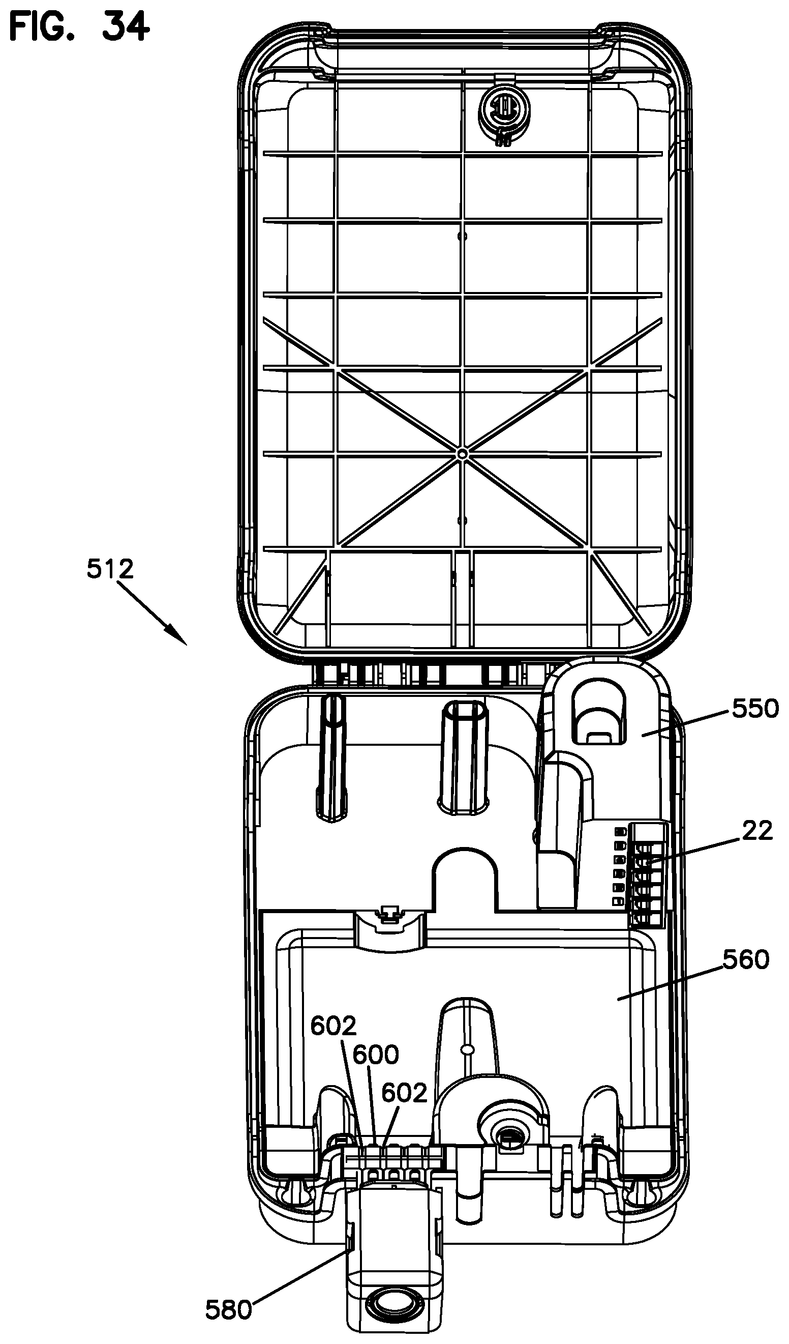
FIG. 34 shows the distribution box of FIGS. 30-33, with various covers in place in the interior, and without the splitters or cables;
FIG. 35 shows the base of the distribution box of FIGS. 30 and 31;
FIGS. 36A and B shows a cover which fits over the slack and splice area on the base of FIG. 35;
FIGS. 37 and 38 show a feeder cable retention device of the distribution box of FIGS. 30 and 31;
FIG. 39 shows a cross-sectional view through the closed distribution box of FIGS. 30 and 31, showing a portion of the lock which holds the cover to the base;
FIG. 40 shows an exploded perspective view of the outgoing cable box of the distribution box of FIG. 30;
FIG. 41 shows a further perspective view of the interior of the distribution box of FIGS. 30 and 31, without any cables shown in the box;
FIG. 42 shows an another view of the distribution box of FIG. 41;
FIG. 43 shows an example of a feeder termination holder of the distribution box of FIGS. 30 and 31;
FIG. 44 shows another example of a feeder termination holder of the distribution box of FIGS. 30 and 31;
FIG. 45 shows a further example of a feeder termination holder of the distribution box of FIGS. 30 and 31;
FIGS. 46 and 47 show a feeder termination cover of the distribution box of FIGS. 30 and 31;
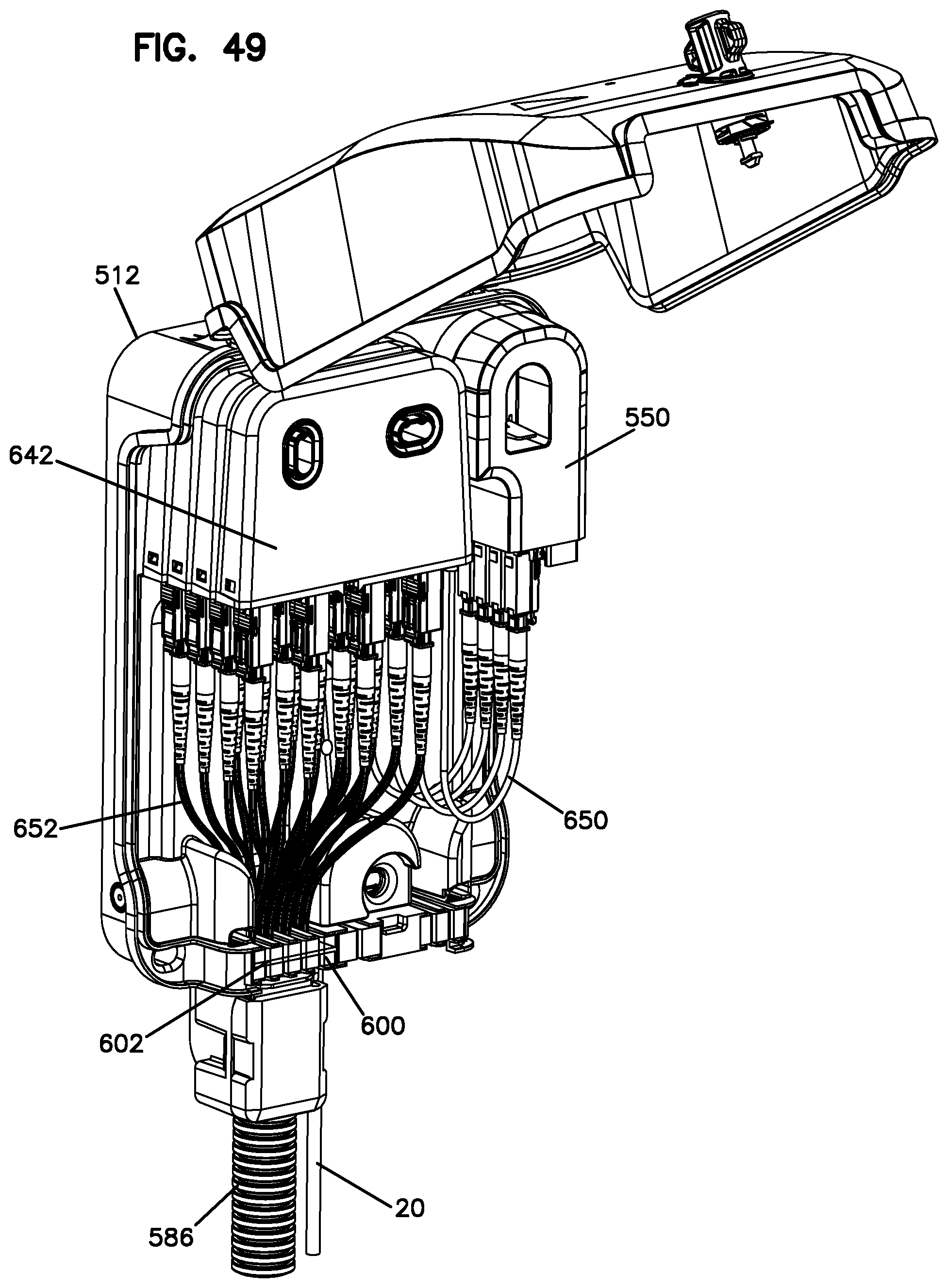
FIGS. 48 and 49 show the distribution box of the distribution box of FIGS. 30 and 31 connected to an input feeder cable and outgoing cables from the splitters;
FIG. 50 shows the distribution box of FIGS. 48 and 49 without any cables connected to the splitter outputs and all the splitter inputs connected to the feeder terminations;
FIG. 51 shows the distribution box of FIGS. 48 and 49 with the addition of the splitter output cables to the view of FIG. 50;
FIG. 52 shows the distribution box of FIGS. 48 and 49 with the addition of two point-to-point connections that connect to the feeder terminations and extend out of the distribution box relative to the view of FIG. 51;
FIG. 53 shows a 1.times.4 splitter for use in the distribution box of FIGS. 30 and 31;
FIG. 54 shows a 1.times.8 splitter for use in the distribution box of FIGS. 30 and 31;
FIG. 55 shows a 1.times.16 splitter for use in the distribution box of FIGS. 30 and 31;
FIG. 56 shows a latching method for connecting a stack of splitters of FIGS. 53-55;
FIG. 57 shows a 1.times.4 splitter of FIG. 53 in exploded view;
FIG. 58 shows a further view of the splitter of FIG. 57;
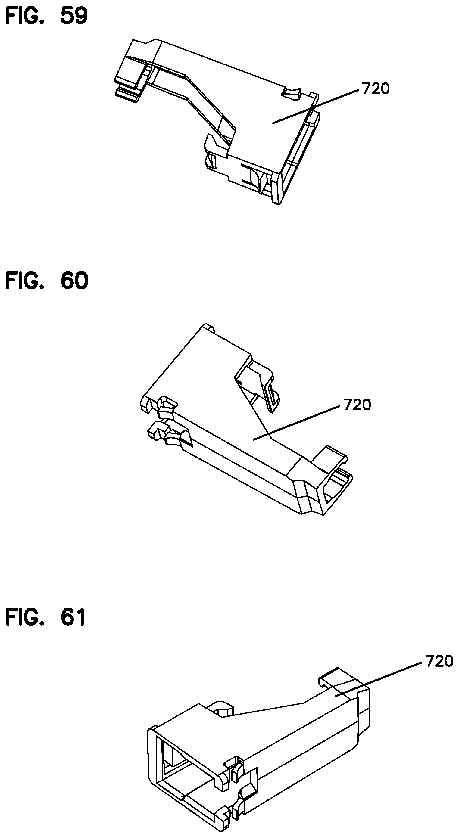
FIGS. 59-61 show a connector holder for use in the splitters of FIGS. 53-55 in various perspective views;
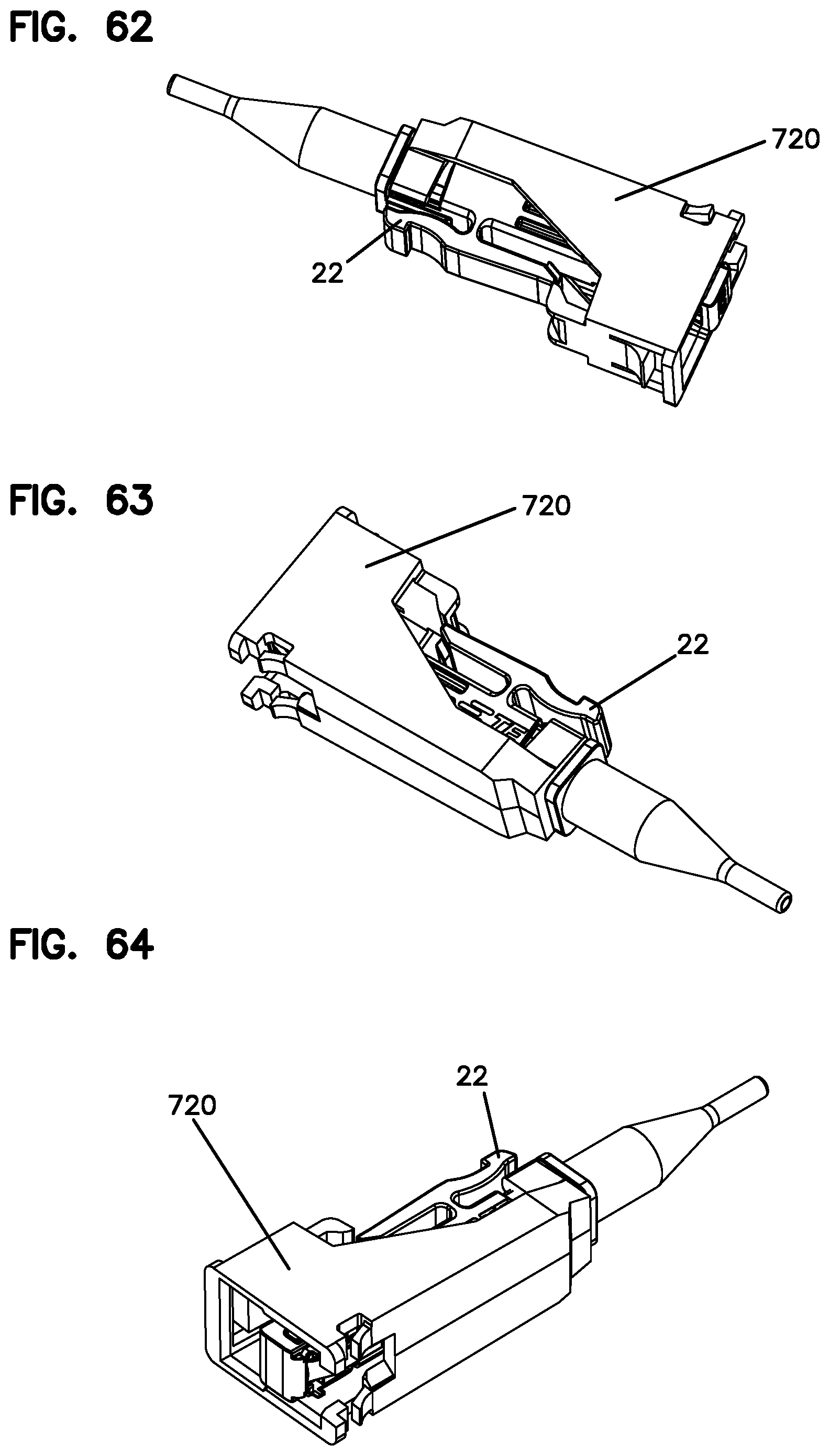
FIGS. 62-64 show the connector holder of FIGS. 59-61 holding a first connector;
FIGS. 65-67 show the connector holder and the connector of FIGS. 62-64, and an adapter mounted to the connector;
FIG. 68 shows an inner housing portion of the 1.times.4 splitter of FIG. 53;
FIG. 69 shows an inner housing portion of the 1.times.8 splitter of FIG. 54;
FIG. 70 shows an inner housing portion of the 1.times.16 splitter of FIG. 55;
FIGS. 71 and 72 show the distribution box of FIGS. 30 and 31 ready to receive splitters;
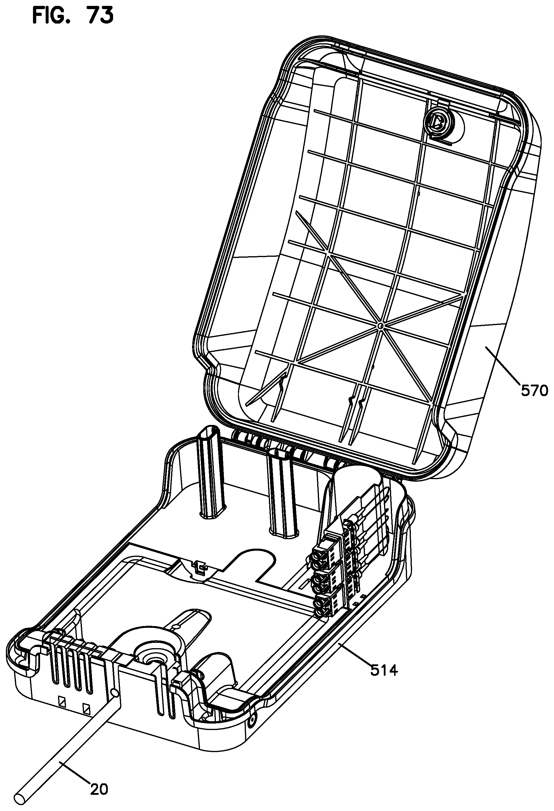
FIGS. 73 and 74 show the distribution box of FIGS. 30 and 31 with the feeder termination cover removed;
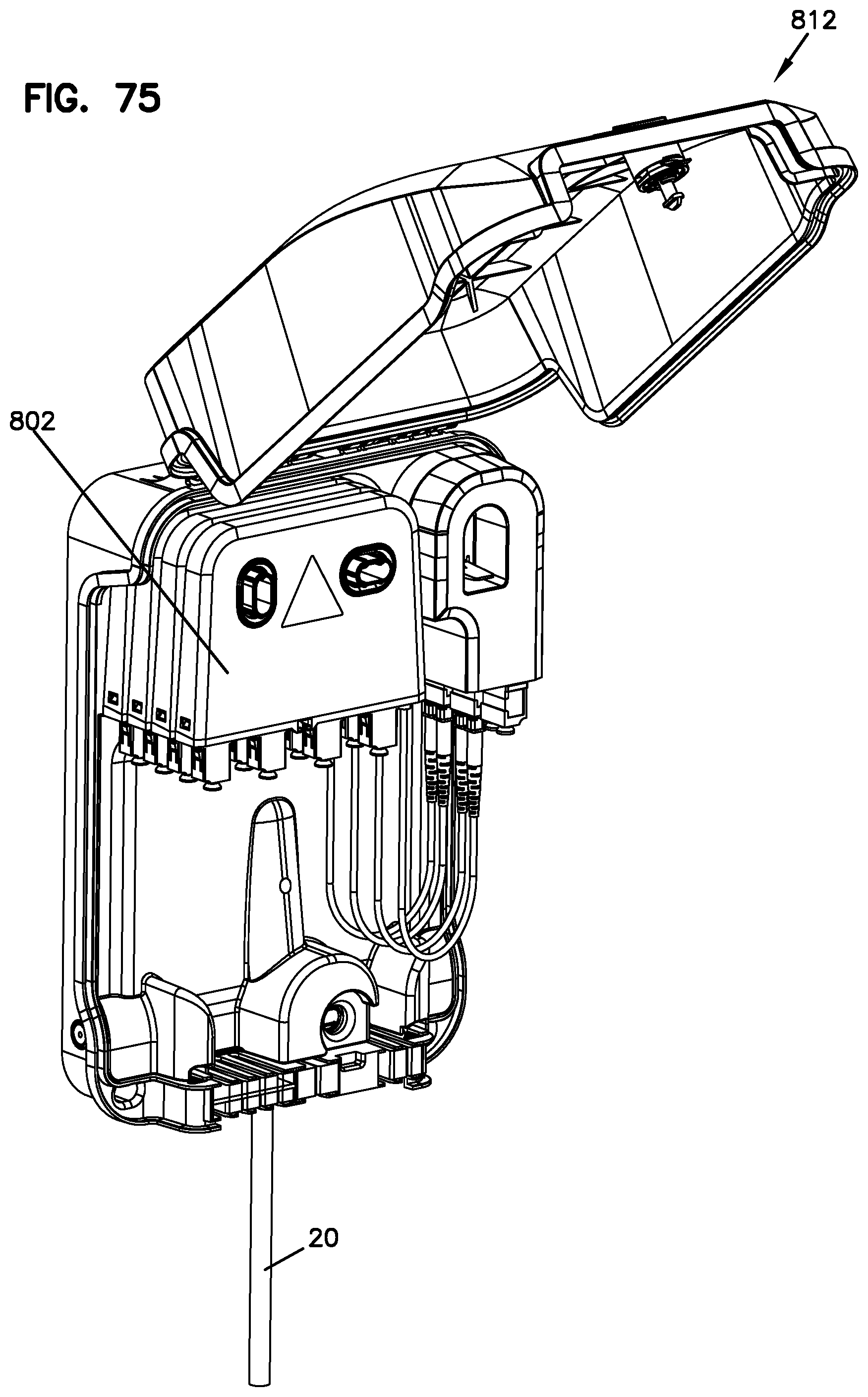
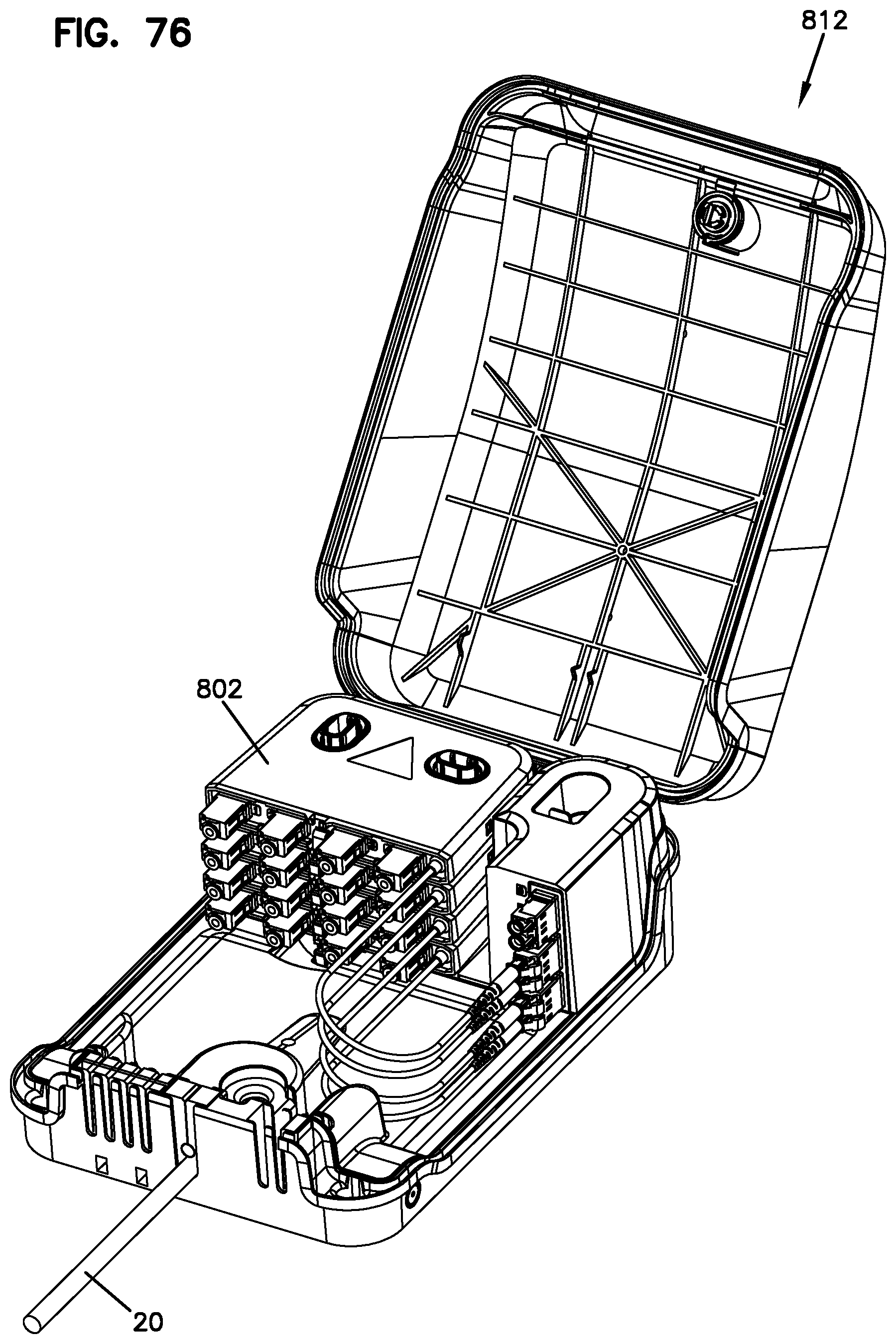
FIGS. 75-77 show the feeder distribution box of FIGS. 30 and 31 connected to splitters and feeder terminations in the form of LC connectors and adapters;
FIG. 78 shows a splitter of the distribution box of FIGS. 75-77 with LC adapters as the splitter outputs for a 1.times.4 splitter;
FIG. 79 shows an alternative splitter utilizing duplex LC adapters for the splitter outputs for a 1.times.8 splitter;
FIG. 80 shows a schematic view illustrating the distribution box of the various embodiments showing feeder fibers connected to splitter outputs and to point-to-point outputs.
DETAILED DESCRIPTION OF THE DRAWINGS
The following descriptions and accompanying drawings show various examples of implementations of the cable distribution systems.
Referring now to FIGS. 1-80, a distribution box receives a feeder cable with one or more feeder fibers. A variety of splitters are shown having a splitter housing mounted to distribution box for splitting of the signals of the feeder fibers. The splitter input in the illustrated examples is in the form of a cable. Within the interior of the splitter, the splitter input is split into a plurality of outputs. The distribution box can hold one or more splitters. A termination field holds connectorized ends of the feeder fibers. Connectorized fibers connect to the feeder fiber connectorized ends at the termination field. The preferred distribution box allows for: 1) split outputs of a splitter input cable connected at the termination field, 2) point to point connection with an output cable at the termination field; or 3) both split feeder signal and point to point feeder signals. FIG. 80 shows this schematically.
Referring further to FIG. 80, the schematic representation of a distribution system 10 includes a distribution box 12 shown offering both point-to-point 14 and split output 16 connections for the feeder cable 20 to the service users. While connectors 22 are shown as LightPlug connectors as the connection interface for the box, adapters could be used instead to connect the two connectors. Using connectors as the interface delays the cost of the adapters 24 until connection is needed. The splitter inputs 28 and the point to point connections are made at termination field 26.
System 10 allows for the later addition of splitters 18 to delay early cost if all of the customers initially can be served by point to point connections. At later date, the splitters can be added once the split outputs are desired.
Referring now to FIGS. 1-4, a distribution box 112 is shown having a base 114 and an input (feeder) cable area 116. The base 114 also includes a splitter area 118 and an area 120 for feeder terminations 122. The base 114 includes one or more storage areas 124. One storage area 126 can be used for cable slack for the cables 130 of the feeder terminations. A second storage area 128 can be used for unused feeder cables 132. The feeder terminations 122 are in the form of LightPlug connectors which are held in place ready for mating to a LightPlug adapter. The feeder terminations can be directly connected to a customer with a point-to-point connection. The feeder terminations can also be connected to a splitter input 140 from a splitter 142 mounted within the distribution box 112, or another distribution box 113. As shown in FIG. 1, a cover 150 encloses the cable storage areas 126, 128. If desired, a splice area can also be provided on the base. Referring to FIG. 1, a further cover 160 is positioned over the feeder terminations 122. A cover 170 covers base 114 and the interior components.
Referring still to now to FIGS. 1-4, various splitters are mounted to the distribution box. The splitter inputs are connected to feeder terminations wherein the feeder signals of those terminations are split into splitter outputs. The splitter outputs are shown as fiber optic connectors disposed within the housings of each splitter. The distribution cable or output cable is connectorized with a mating connector and a mating adapter for connecting to the splitter outputs.
As shown in FIG. 1, there are six feeder terminations, three of which are connected to splitters of one distribution box 112, and three of which are connected to another distribution box 113. Any still open feeder terminations can be directly connected to a customer in a point-to-point arrangement, or can be connected to further splitter inputs of additional splitters. A box cover 170 typically is placed over the splitters, the feeder terminations, and the base to protect the interior. Cable management devices 190 help to manage the output cables.
As shown in FIG. 1, a second dummy-box 113 can be mounted next to the initially installed box 112. Extra splitters 142 can be mounted in this second box 113, the inputs from the added splitters are patched to one of the terminated connectors from the first box 112. Feeder terminations 134 of box 113 are not used in the arrangement of FIG. 1.
As shown in FIG. 2, a second box 113 can be mounted next to the initially installed box 112. One un-used fiber bundle/tube 132 from the feeder 20 is routed to the new box to the 250 .mu.m overlength compartment 130. After stripping to 250 .mu.m. The second box 113 can be installed similar to the first box 112. Depending on the feeder-cable, more boxes can be connected. Feeder terminations 134 of box 113 are used in the arrangement of FIG. 2.
FIG. 3 shows an example of feeder cable installation which results in terminated fibers which can be connected in a point-to-point arrangement with a customer, or to a splitter, and then to the costumer(s) as desired. In the illustrated example, six terminated feeder fibers are provided. Other examples can include more or less terminated fibers for the distribution box. FIG. 3 also shows the distribution box at initial installation lacking any splitters, and only providing direct point-to-point connections with the customers. If desired, at a later date, a splitter can be added to provide additional outputs for customers. Additional splitters can be added at that time, or at a later date, as desired. This helps defer costs. FIG. 3 shows distribution box 112 with an unused fiber bundle/tube 132 in storage 3 area 128, ready for future use, such as for repair, or connection to another box 113.
As shown in FIG. 4, a second box 113 can be mounted somewhere in the neighborhood and feeder-fibers from un-used bundles/tubes 132 are spliced in box 112 to a feeder-cable 198 which runs to the second box 113. This spliced feeder-stub enters the second box 113 in the same way the feeder 20 enters the first box 112. Feeder terminations 134 of box 113 are used in the arrangement of FIG. 2. Depending on the feeder-cable, more boxes can be connected in a daisy-chaining manner.
The example splitters 142 include a splitter input cable 172 and 174 and multiple outputs formed at the splitter housing. Different lengths of cables 172 and 174 can be provided if necessary. Various examples are shown of different splitter sizes and variations in the number of splitter outputs. As shown, the splitters 142 can have different thicknesses in multiples of T thickness. Each splitter 142 includes one or more holes 182 to receive posts 180 of base 114. The holes can be round or oval, or another shape.
In FIGS. 1-4, splitter 142 includes splitter outputs in the form of connectors 178 mounted at and/or within the splitter housing 144. The splitter input 172, 174 connects to the feeder terminations 122 in the form of connectors 22. The cable stub 172, 174 extending from the splitter housing 144 connectors 22 and adapters 24 disposed at the distal ends of the cable stubs. Adapters 24 can be used instead as the demarcation point for the splitter outputs 16 and/or for the feeder terminations.
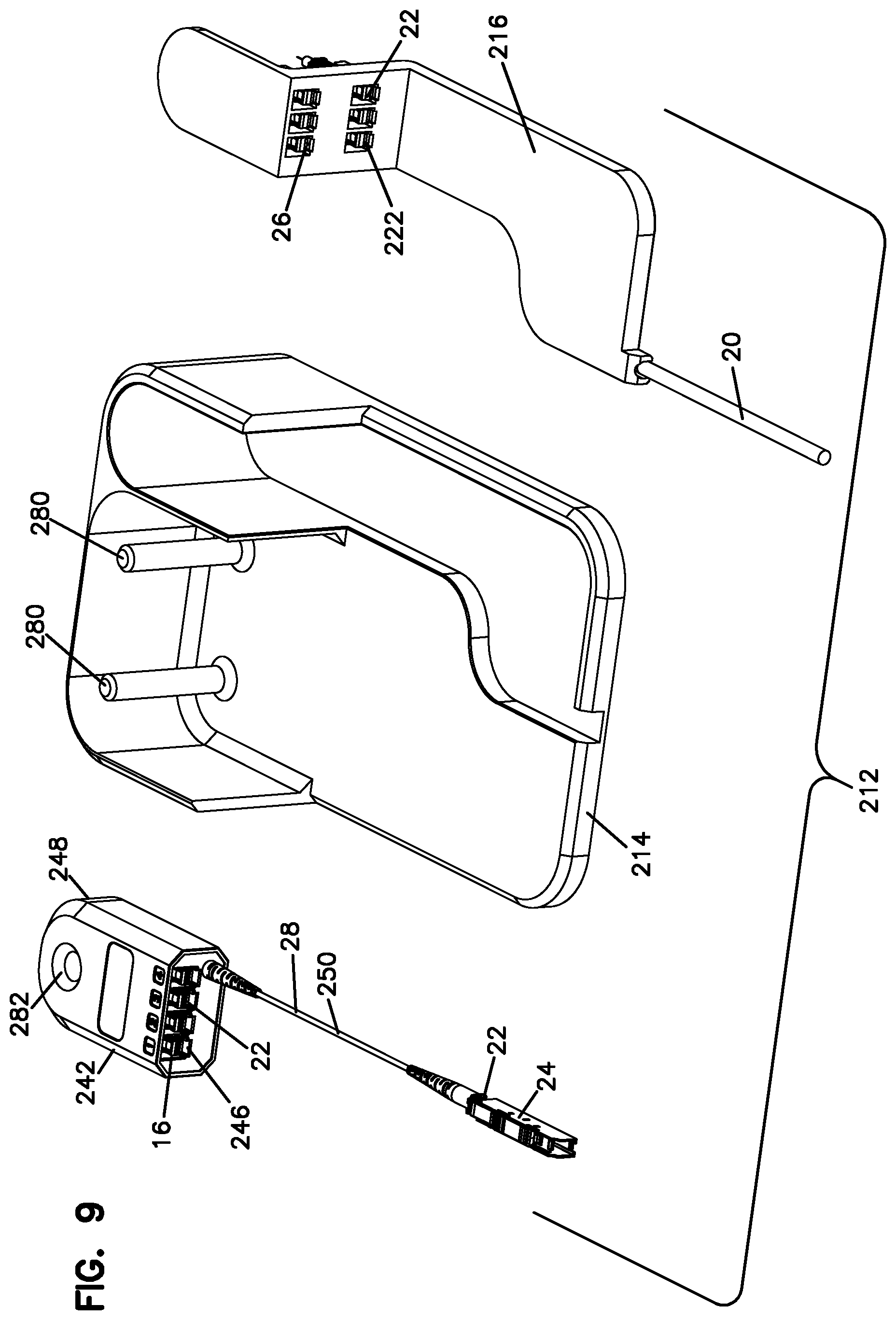
FIGS. 5-16 show an alternative distribution box 212 having a base 214 wherein the feeder cable 20 is mounted to a cover 216 along with the feeder terminations 222. Such a construction allows the feeder terminations to be worked on or accessed by a technician separate from the base 214, as desired. Cover 216 includes a cable storage area 224 on a back side of the cover. The example splitters 242 include a splitter input cable 250 and multiple outputs 246 formed at the splitter housing 248. Various examples are shown of different splitter sizes and variations in the number of splitter outputs. As shown, the splitters 242 can have different thicknesses in multiples of T thickness and/or different widths in multiples of W widths. Each splitter 242 includes one or more holes 282 to receive posts 280 of base 114. A cover like cover 170 can be provided.
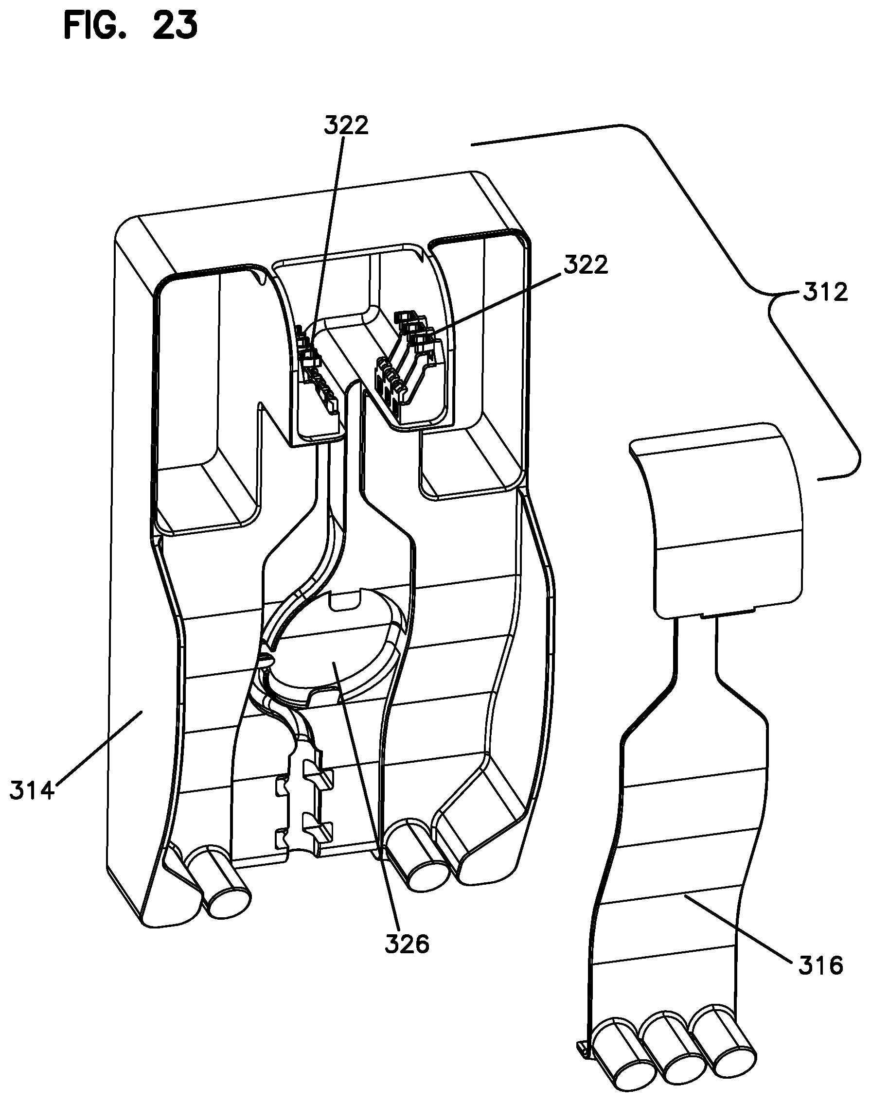
Referring now to FIGS. 17-25, various embodiments of a distribution box 312 and splitters 342 are shown including the cable stubs 344 extending from the splitter housing 346 to form the splitter outputs. Box 312 includes a base 314 and a middle cover 316 over cable storage area 326 on base 314. Each splitter 342 has a splitter input 350 in the form of a cable. A cover like cover 170 can be provided. The use of a splitter with the fiber stubs for the outputs of the splitter can improve density, and connector and adapter access.
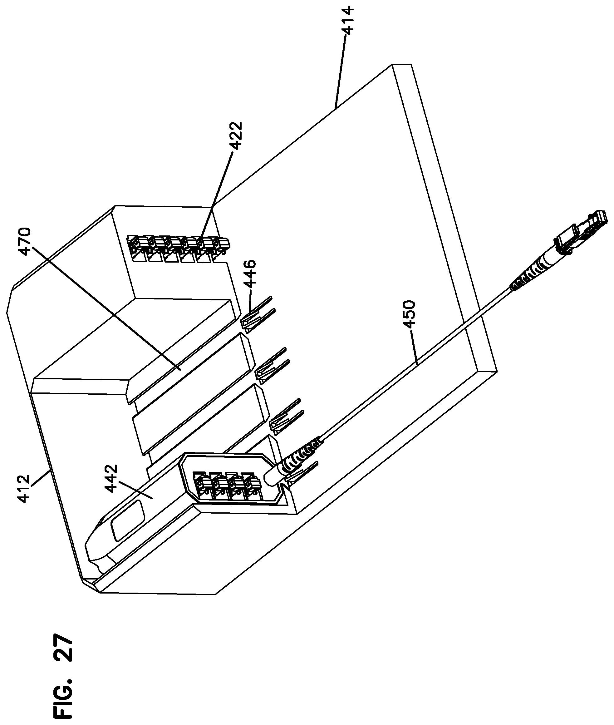
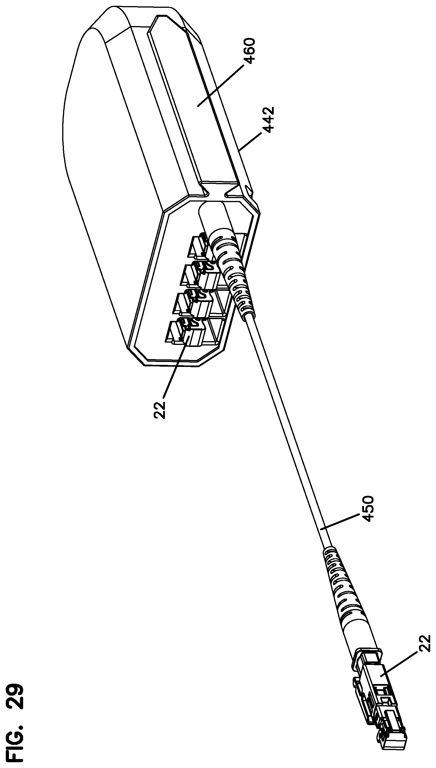
Referring now to FIGS. 26-29, a further embodiment of a distribution box 412 and splitters 442 are shown. The splitters 442 slidably mount parallel to the base 414. The splitters 442 can be individually removed or partially removed to improve access to the splitter outputs. Each splitter 442 has a splitter input 450. FIG. 44 shows a splitter retention clip or latch 446 for retaining the splitter 442 with the base 414. A cover like cover 170 can be provided. Splitters 442 slide relative to base 114 with an interlocking slide. As shown, splitters 442 include a dovetail projection 460, and base 414 includes a mating slot 470. As also shown, feeder terminations 422 have four connectors 22 connected to one of each of the four splitter inputs 450. The two open connectors 22 are available for point to point connections or connections to other splitters in other boxes 412.
As shown in FIGS. 26-29, the splitters 442 are located orthogonal to the splitters previously noted. Such positioning is an alternative positioning. The splitter inputs are located closest to the base 414 in this example.
FIGS. 1-29 all use a LightPlug connector and adapter. A LightPlug installation tool permits a bare fiber to be inserted into the tool, and the tool adds the LightPlug connector to the end of the fiber to terminate the fiber. Use of the LightPlug installation tool and the LightPlug connectors and mating adapters provide just one embodiment of the present distribution system. Each splitter output is in the form of a fiber optic connector, including a shutter. The illustrated connectors are LightPlug connectors. The splitter input has a LightPlug connector at a distal end mated with a LightPlug adapter. The LightPlug adapter is connectable to a distribution cable terminated with a LightPlug connector. The LightPlug tool, connector and adapter system is shown in patent document nos. WO2012/112344 and WO 2013/117598, noted previously incorporated by reference. Other forms of connectors, including SC and LC can be used, in addition to multi-fiber connectors, such as MPO connectors.
The splitters can include port identifiers, a splitter identifier, and an RFID tag, if desired.
Various arrangements of splitters are shown with different numbers of splitter outputs. These splitters can be mixed and matched in the distribution boxes as desired.
The LightPlug feeder terminations are shown connected to the base. The connectors are held with clips ready for connection to an adapter, which is added later in combination with a second connector for connection to a customer or the splitters. Alternatively, adapters can be mounted to the base.
As noted, various implementations are provided for adding capacity over time. One implementation is to add the splitters as needed over time. Another implementation for adding capacity uses two distribution boxes. Splitters from the second distribution box can be connected to feeder terminations of the first distribution box. Another implementation for adding capacity includes a feeder cable connected to two (or more) distribution boxes as desired. This provides additional feeder terminations for connections to customers directly, or through splitters. Another implementation for increasing capacity includes adding a second (or more) distribution box at a remote location wherein a further feeder cable is spliced to the first feeder cable to link the two distribution boxes. Another implementation is to add a new cover 170 to the distribution box to add increased outputs through the use of larger splitters.
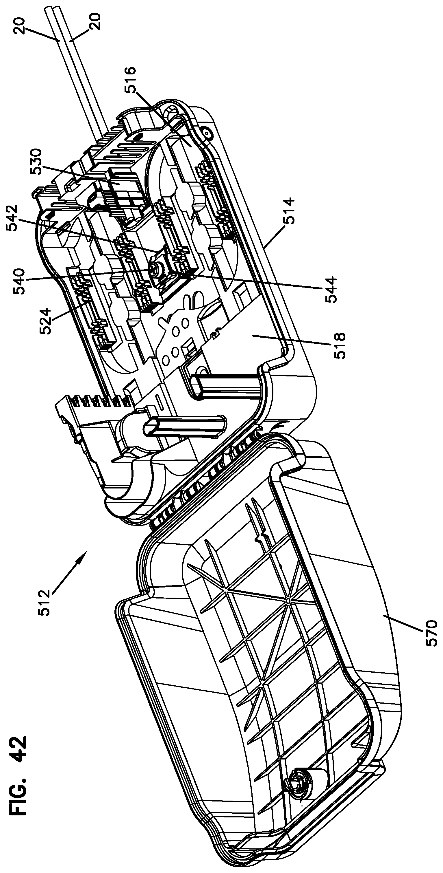
Referring now to FIGS. 30-79, an alternative distribution box 512 is shown. The distribution box includes a cover 570, a base 514, a lock 572 (with a key 573) for the cover, a connection box 580 to secure a corrugated tube 582 for housing cables, and an internal tray 516 used for cable routing and storage (and splice). Cover 570 is hinged at hinge 574 to base 514. A splitter area 518 holds splitters on one or more posts 526, 528. Posts 526, 528 can be different shapes and/or sizes to facilitate one way fit with the splitters 642 (see FIG. 48). The feeder cables 20 pass through a channel 536 and are terminated at a feeder termination area 522.
An internal cover 560 is positioned over the splice and storage area 524. A termination cover 560 is also provided. The internal cover 560, or demarcation cover, fits over the storage and splice area 524. Tabs 562 and snaps 564 are used to mount the demarcation cover 560 to the base 514. Handles 566 are provided on cover 560. The left side of area 524 can be used to store active fibers. The right side of area 524 can be used to store dark fibers or unused fibers. Both the left and right sides of the area 524 can be used to store splice holders.
A feeder cable clamping device 530 is shown for use in the distribution box. The clamping device 530 includes arms 532 which squeeze one or more feeder cables upon mounting of the demarcation cover 560 to the base. The feeder cable clamping device 530 can be in the form of a separate part mounted to the base. Arms 568 extend from cover 560 to restrain clamping device 530 and force them to clamp to the cables. Inner teeth can also be provided on arms 532 to grip the cables.
A strength member clamp 540 is shown positioned between a portion of the base 546 and a metal clamping plate 544. A ramp 542 promotes upward movement of the strength member to the clamping location.
Feeder termination inserts 590 are shown for holding connectors and/or adapters associated with the feeder terminations. The insert 590 snaps to the base 514. Different inserts 590 are provided for different connectors or adapters. FIG. 43 includes openings 592 for LightPlug connectors 22. FIG. 44 includes openings 594 for three SC or LC connectors 22. FIG. 45 includes an opening 596 for six SC or LC connectors 22 or other connectors.
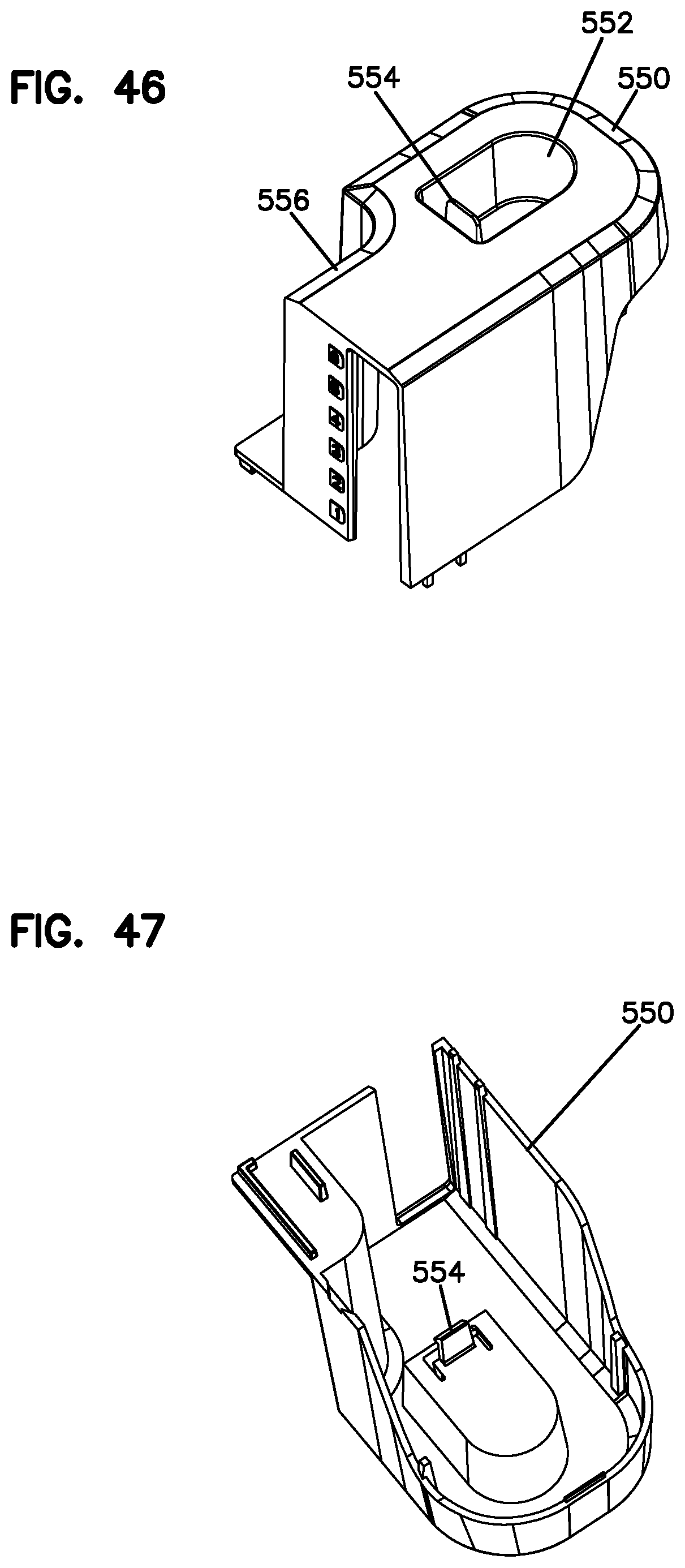
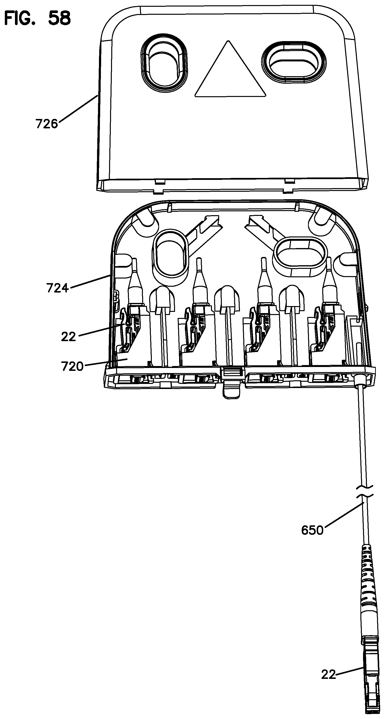
A feeder termination cover or tower cover 550 is shown for use in covering the feeder input cables. A latch 554 holds the termination cover 550 in place. A finger recess 552 allows for finger activation of the latch 554. A cutout 556 allows for finger access for the installer or technician for handling of the adjacent splitters.
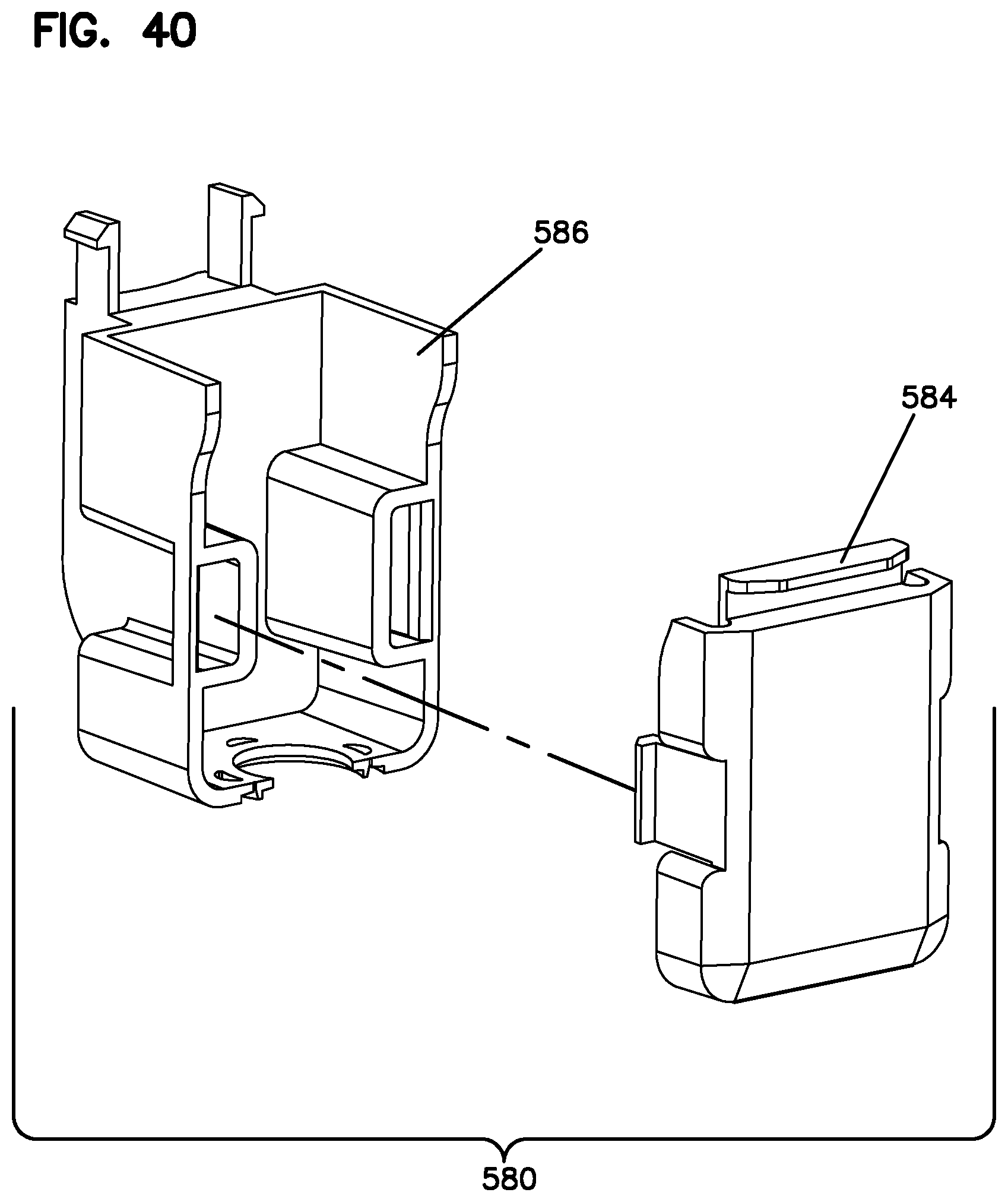
The connection box 580 is made of two pieces 584, 586 and connects a flexible conduitor corrugated tube 586 to the distribution box 512 for organizing and protecting the distribution or output cables extending from the box. Connection box 580 snaps to base 514. Preferably, a foam insert 600 with slits 602 is used on the base to provide a seal around the cables entering the connection box.
The cover lock 572 is shown wherein a key 573 engages a turning element to open and close the lock. In general, the key cannot be removed from the cover unless the cover is closed and the lock is locked. Additional details of the lock and key are shown and described U.S. Application Ser. No. 62/073,631, the disclosure of which is hereby incorporated by reference in its entirety.
Referring to FIGS. 48-52, a feeder cable 20 is terminated at the feeder terminations 522. Input cables 650 from the splitters 642 are shown connected to the feeder terminations 522 to provide input signals for each of the splitters 642 for splitting and connection to distribution cables 652. FIG. 52 also shows some of the feeder terminations 522 are connected to individual cables for point-to-point connections where the use of a split output is not desired. FIGS. 48-52 also illustrate the use of LightPlug connectors and adapters.
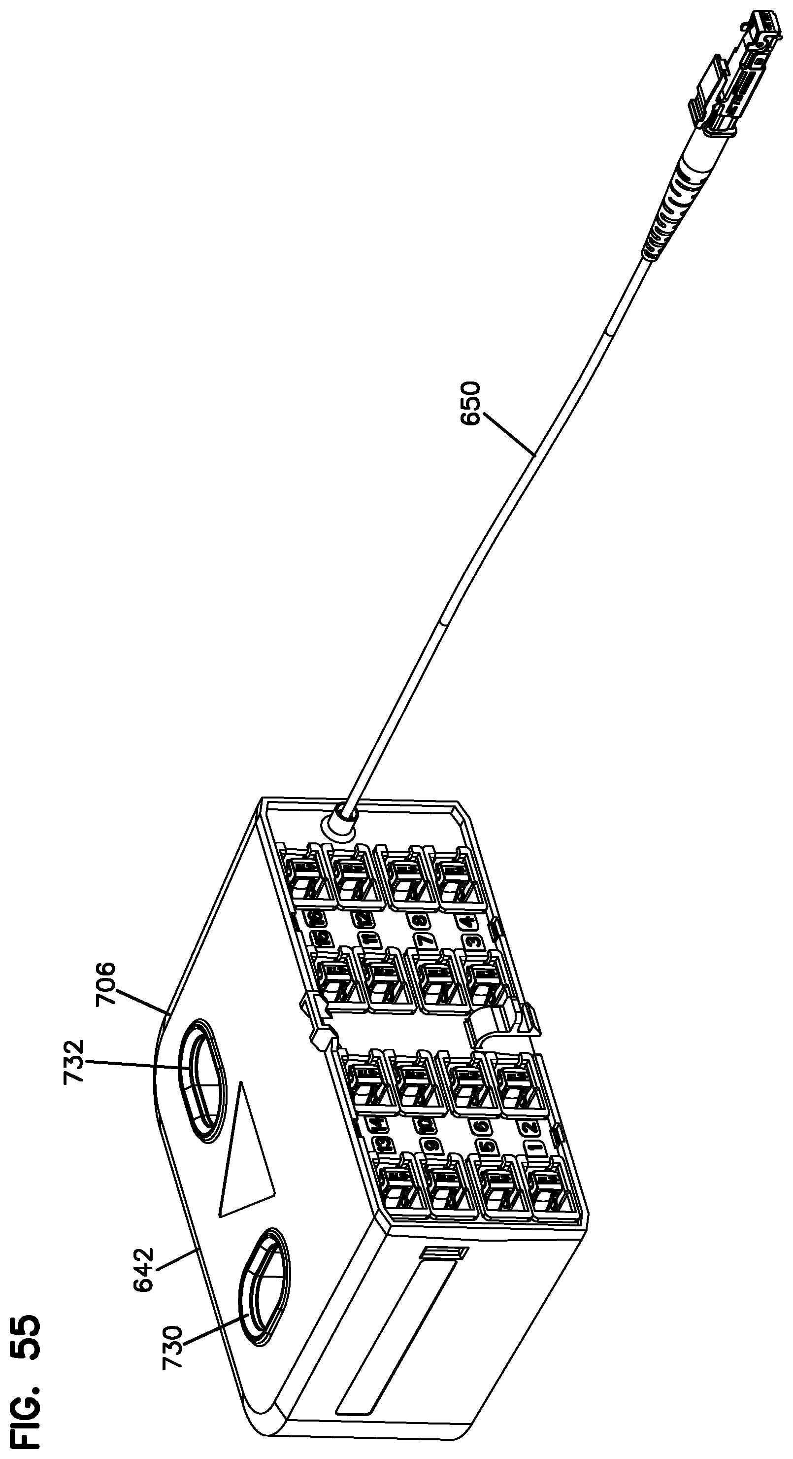
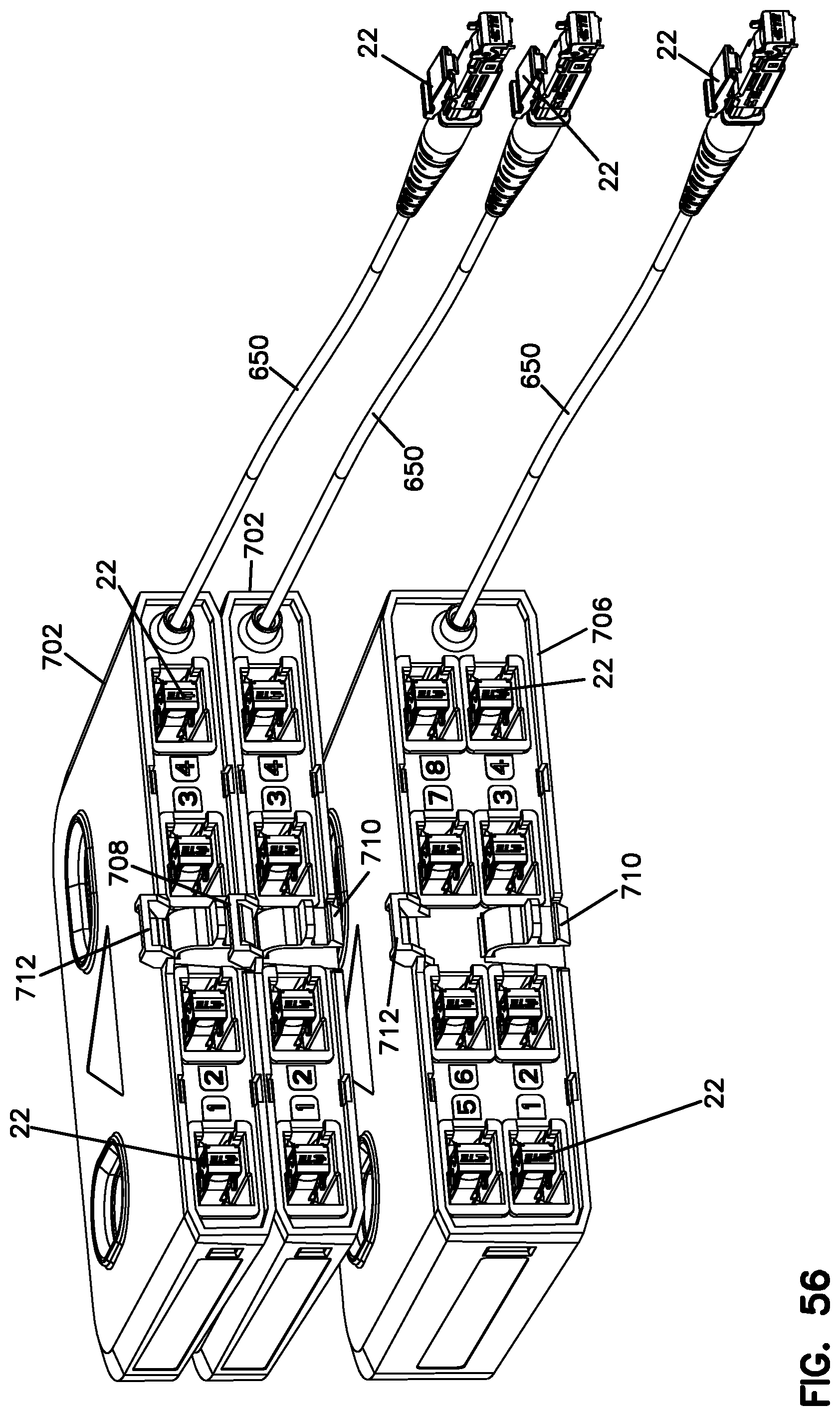
Referring now to FIGS. 53-70 various views are shown of splitters or splitter cassettes. The splitters can take many forms and formats. In general, a common profile is provided for use with the distribution box. FIG. 53 shows a 1.times.4 splitter 702. FIG. 54 shows a 1.times.8 splitter 704. FIG. 55 shows a 1.times.16 splitter 706. FIGS. 53-55 show a common profile, but different heights.
FIG. 56-70 show the splitter output ports in greater detail in the form of the LightPlug connector 22. FIG. 56 also shows a snap feature tomable extending (latch 710, socket 712) for connecting two splitters together or for connecting one splitter to the base. This feature is useful for removing the need for a separate Velcro strap or other fixation device. FIGS. 57-67 show one example of a LightPlug connector retainer 720 utilized utilized with an internal splitter tray 724 for holding the splitter outputs ready for connection to distribution cables. LightPlug connector retainer 720 includes snaps to mount to a splitter module. Splitter tray 724 fits into splitter cover or housing 726. Splitters 702, 704, 706 include oval openings 730, 732 for mating with posts 526, 528. Referring now to FIG. 70, a double sided internal splitter tray is utilized in a 1.times.16 splitter configuration. Various snaps are utilized to connect the inner trays to the outer cover of the splitters. FIGS. 71-74 show further views of the box 512 with the cover in the open position.
FIGS. 75-80 show similar splitters as shown with the distribution box of FIGS. 30-74, but utilizing LC adapters and connectors for the various fiber connections of the distribution box. As shown, LC adapters define the feeder terminations 804 and also the splitter outputs of splitters 802 which can be connected to distribution cables terminated with LC connectors. Further, the splitter inputs are provided with one or more pigtails terminated by a LC connector connectable to one or more of the adapters, one or more of the LC adapters of the feeder terminations. As shown, the LC adapters can be duplex or simplex adapters. MPO connectors and adapters can also be used. 10 distribution system 12 distribution box 14 point-to-point 16 split output 18 splitters 20 feeder 22 connectors 24 adapters 26 termination field 28 splitter inputs 112 box 113 box 114 base 116 cable area 118 splitter area 120 area 122 feeder terminations 124 storage areas 126 cable storage areas 128 cable storage areas 130 cables 132 one un-used fiber bundle/tube 134 feeder terminations 140 splitter input 142 extra splitters 144 splitter housing 150 cover 160 cover 170 box cover 172 cable stub 174 cable stub 178 connectors 180 posts 182 holes 190 cable management devices 198 feeder-cable 212 alternative distribution box 214 base 216 cover 222 feeder terminations 224 cable storage area 242 splitter 246 multiple outputs 248 splitter housing 250 splitter input cable 280 posts 282 holes 312 box 314 base 316 middle cover 326 cable storage area 342 splitter 344 cable stubs 346 splitter housing 350 splitter input 412 distribution box 414 base 422 feeder terminations 442 splitter 446 latch 450 splitter input 460 dovetail projection 470 mating slot 512 distribution box 514 base 516 internal tray 518 splitter area 522 feeder termination area 524 area 526 posts 528 posts 530 clamping device 532 arms 536 channel 540 strength member clamp 542 ramp 544 metal clamping plate 546 base 550 termination cover 552 finger recess 554 latch 556 cutout 560 cover 562 tabs 564 snaps 566 handles 568 arms 570 cover 572 cover lock 573 key 574 hinge 580 connection box 582 corrugated tube 584 two pieces 586 flexible conduitor corrugated tube 590 feeder termination inserts 592 openings 594 openings 596 opening 600 foam insert 602 slits 642 splitters 650 input cables 652 distribution cables 702 splitter 704 splitter 706 splitter 710 latch 712 socket 720 lightplug connector retainer 724 internal splitter tray 726 housing 730 oval openings 732 oval openings 802 splitters 804 feeder terminations
* * * * *
References
D00000
D00001
D00002
D00003
D00004
D00005
D00006
D00007
D00008
D00009
D00010
D00011
D00012

D00013

D00014

D00015

D00016

D00017

D00018
D00019

D00020

D00021

D00022
D00023

D00024
D00025

D00026

D00027

D00028

D00029
D00030

D00031

D00032

D00033

D00034
D00035

D00036
D00037

D00038

D00039

D00040
D00041

D00042
D00043

D00044

D00045

D00046

D00047

D00048
D00049
D00050

D00051
D00052
D00053
D00054

D00055

D00056

D00057

D00058
D00059

D00060
D00061
D00062

D00063

D00064

D00065

XML
uspto.report is an independent third-party trademark research tool that is not affiliated, endorsed, or sponsored by the United States Patent and Trademark Office (USPTO) or any other governmental organization. The information provided by uspto.report is based on publicly available data at the time of writing and is intended for informational purposes only.
While we strive to provide accurate and up-to-date information, we do not guarantee the accuracy, completeness, reliability, or suitability of the information displayed on this site. The use of this site is at your own risk. Any reliance you place on such information is therefore strictly at your own risk.
All official trademark data, including owner information, should be verified by visiting the official USPTO website at www.uspto.gov. This site is not intended to replace professional legal advice and should not be used as a substitute for consulting with a legal professional who is knowledgeable about trademark law.